EP4254630A1 - Wire harness isolation plate and battery module - Google Patents
Wire harness isolation plate and battery module Download PDFInfo
- Publication number
- EP4254630A1 EP4254630A1 EP22818607.8A EP22818607A EP4254630A1 EP 4254630 A1 EP4254630 A1 EP 4254630A1 EP 22818607 A EP22818607 A EP 22818607A EP 4254630 A1 EP4254630 A1 EP 4254630A1
- Authority
- EP
- European Patent Office
- Prior art keywords
- battery cell
- fixed
- fixed plate
- wire harness
- electrode
- Prior art date
- Legal status (The legal status is an assumption and is not a legal conclusion. Google has not performed a legal analysis and makes no representation as to the accuracy of the status listed.)
- Pending
Links
Images



Classifications
-
- H—ELECTRICITY
- H01—ELECTRIC ELEMENTS
- H01M—PROCESSES OR MEANS, e.g. BATTERIES, FOR THE DIRECT CONVERSION OF CHEMICAL ENERGY INTO ELECTRICAL ENERGY
- H01M50/00—Constructional details or processes of manufacture of the non-active parts of electrochemical cells other than fuel cells, e.g. hybrid cells
- H01M50/20—Mountings; Secondary casings or frames; Racks, modules or packs; Suspension devices; Shock absorbers; Transport or carrying devices; Holders
- H01M50/204—Racks, modules or packs for multiple batteries or multiple cells
- H01M50/207—Racks, modules or packs for multiple batteries or multiple cells characterised by their shape
- H01M50/213—Racks, modules or packs for multiple batteries or multiple cells characterised by their shape adapted for cells having curved cross-section, e.g. round or elliptic
-
- H—ELECTRICITY
- H01—ELECTRIC ELEMENTS
- H01M—PROCESSES OR MEANS, e.g. BATTERIES, FOR THE DIRECT CONVERSION OF CHEMICAL ENERGY INTO ELECTRICAL ENERGY
- H01M50/00—Constructional details or processes of manufacture of the non-active parts of electrochemical cells other than fuel cells, e.g. hybrid cells
- H01M50/20—Mountings; Secondary casings or frames; Racks, modules or packs; Suspension devices; Shock absorbers; Transport or carrying devices; Holders
- H01M50/298—Mountings; Secondary casings or frames; Racks, modules or packs; Suspension devices; Shock absorbers; Transport or carrying devices; Holders characterised by the wiring of battery packs
-
- H—ELECTRICITY
- H01—ELECTRIC ELEMENTS
- H01M—PROCESSES OR MEANS, e.g. BATTERIES, FOR THE DIRECT CONVERSION OF CHEMICAL ENERGY INTO ELECTRICAL ENERGY
- H01M50/00—Constructional details or processes of manufacture of the non-active parts of electrochemical cells other than fuel cells, e.g. hybrid cells
- H01M50/20—Mountings; Secondary casings or frames; Racks, modules or packs; Suspension devices; Shock absorbers; Transport or carrying devices; Holders
- H01M50/258—Modular batteries; Casings provided with means for assembling
-
- H—ELECTRICITY
- H01—ELECTRIC ELEMENTS
- H01M—PROCESSES OR MEANS, e.g. BATTERIES, FOR THE DIRECT CONVERSION OF CHEMICAL ENERGY INTO ELECTRICAL ENERGY
- H01M50/00—Constructional details or processes of manufacture of the non-active parts of electrochemical cells other than fuel cells, e.g. hybrid cells
- H01M50/20—Mountings; Secondary casings or frames; Racks, modules or packs; Suspension devices; Shock absorbers; Transport or carrying devices; Holders
- H01M50/262—Mountings; Secondary casings or frames; Racks, modules or packs; Suspension devices; Shock absorbers; Transport or carrying devices; Holders with fastening means, e.g. locks
- H01M50/264—Mountings; Secondary casings or frames; Racks, modules or packs; Suspension devices; Shock absorbers; Transport or carrying devices; Holders with fastening means, e.g. locks for cells or batteries, e.g. straps, tie rods or peripheral frames
-
- H—ELECTRICITY
- H01—ELECTRIC ELEMENTS
- H01M—PROCESSES OR MEANS, e.g. BATTERIES, FOR THE DIRECT CONVERSION OF CHEMICAL ENERGY INTO ELECTRICAL ENERGY
- H01M50/00—Constructional details or processes of manufacture of the non-active parts of electrochemical cells other than fuel cells, e.g. hybrid cells
- H01M50/50—Current conducting connections for cells or batteries
-
- H—ELECTRICITY
- H01—ELECTRIC ELEMENTS
- H01M—PROCESSES OR MEANS, e.g. BATTERIES, FOR THE DIRECT CONVERSION OF CHEMICAL ENERGY INTO ELECTRICAL ENERGY
- H01M50/00—Constructional details or processes of manufacture of the non-active parts of electrochemical cells other than fuel cells, e.g. hybrid cells
- H01M50/50—Current conducting connections for cells or batteries
- H01M50/502—Interconnectors for connecting terminals of adjacent batteries; Interconnectors for connecting cells outside a battery casing
- H01M50/503—Interconnectors for connecting terminals of adjacent batteries; Interconnectors for connecting cells outside a battery casing characterised by the shape of the interconnectors
-
- H—ELECTRICITY
- H01—ELECTRIC ELEMENTS
- H01M—PROCESSES OR MEANS, e.g. BATTERIES, FOR THE DIRECT CONVERSION OF CHEMICAL ENERGY INTO ELECTRICAL ENERGY
- H01M50/00—Constructional details or processes of manufacture of the non-active parts of electrochemical cells other than fuel cells, e.g. hybrid cells
- H01M50/50—Current conducting connections for cells or batteries
- H01M50/502—Interconnectors for connecting terminals of adjacent batteries; Interconnectors for connecting cells outside a battery casing
- H01M50/507—Interconnectors for connecting terminals of adjacent batteries; Interconnectors for connecting cells outside a battery casing comprising an arrangement of two or more busbars within a container structure, e.g. busbar modules
-
- H—ELECTRICITY
- H01—ELECTRIC ELEMENTS
- H01M—PROCESSES OR MEANS, e.g. BATTERIES, FOR THE DIRECT CONVERSION OF CHEMICAL ENERGY INTO ELECTRICAL ENERGY
- H01M50/00—Constructional details or processes of manufacture of the non-active parts of electrochemical cells other than fuel cells, e.g. hybrid cells
- H01M50/50—Current conducting connections for cells or batteries
- H01M50/569—Constructional details of current conducting connections for detecting conditions inside cells or batteries, e.g. details of voltage sensing terminals
-
- H—ELECTRICITY
- H01—ELECTRIC ELEMENTS
- H01M—PROCESSES OR MEANS, e.g. BATTERIES, FOR THE DIRECT CONVERSION OF CHEMICAL ENERGY INTO ELECTRICAL ENERGY
- H01M50/00—Constructional details or processes of manufacture of the non-active parts of electrochemical cells other than fuel cells, e.g. hybrid cells
- H01M50/50—Current conducting connections for cells or batteries
- H01M50/572—Means for preventing undesired use or discharge
- H01M50/584—Means for preventing undesired use or discharge for preventing incorrect connections inside or outside the batteries
- H01M50/59—Means for preventing undesired use or discharge for preventing incorrect connections inside or outside the batteries characterised by the protection means
- H01M50/593—Spacers; Insulating plates
-
- H—ELECTRICITY
- H01—ELECTRIC ELEMENTS
- H01M—PROCESSES OR MEANS, e.g. BATTERIES, FOR THE DIRECT CONVERSION OF CHEMICAL ENERGY INTO ELECTRICAL ENERGY
- H01M2220/00—Batteries for particular applications
- H01M2220/20—Batteries in motive systems, e.g. vehicle, ship, plane
-
- Y—GENERAL TAGGING OF NEW TECHNOLOGICAL DEVELOPMENTS; GENERAL TAGGING OF CROSS-SECTIONAL TECHNOLOGIES SPANNING OVER SEVERAL SECTIONS OF THE IPC; TECHNICAL SUBJECTS COVERED BY FORMER USPC CROSS-REFERENCE ART COLLECTIONS [XRACs] AND DIGESTS
- Y02—TECHNOLOGIES OR APPLICATIONS FOR MITIGATION OR ADAPTATION AGAINST CLIMATE CHANGE
- Y02E—REDUCTION OF GREENHOUSE GAS [GHG] EMISSIONS, RELATED TO ENERGY GENERATION, TRANSMISSION OR DISTRIBUTION
- Y02E60/00—Enabling technologies; Technologies with a potential or indirect contribution to GHG emissions mitigation
- Y02E60/10—Energy storage using batteries
Definitions
- the present disclosure relates to the field of power battery, for example, relates to a wire harness isolation plate and a battery module.
- a battery module includes a plurality of battery cells, and the battery cells are connected in series or parallel through a busbar.
- a busbar is connected to the battery cell, and a connection therebetween is unstable. The short circuit is easy to occur between different busbars, and between the busbar and the battery cell.
- an insulation structure is generally applied for insulation between the battery cells, between the busbars, and between the busbar and the battery cell. However, it is difficult to make the insulation structure, which increases the cost.
- the battery module has a plurality of battery cells and a plurality of busbars, and a number of components is large, resulting in low assembly efficiency.
- the present disclosure provides a wire harness isolation plate and a battery module.
- the wire harness isolation plate can provide an insulated isolation between busbars, between battery cells, and between the busbars and the battery cells, so that a structure of the battery module is stable and simple.
- the harness isolation plate is configured to integrate the busbar, which is conducive to an integrated design of cells contact system (CCS) assembly and improves a grouping efficiency of the busbars.
- CCS cells contact system
- an embodiment of the present disclosure provides a harness isolation plate, the wire harness isolation plate is disposed on a battery cell module, the battery cell module includes a plurality of battery cells and a plurality of busbars, each of the busbars is configured to connect with at least two battery cells in the battery cell module, and a first electrode and a second electrode of each of the battery cells are disposed on a same side of the battery cell; wherein the wire harness isolation plate includes a first fixed unit, the first fixed unit includes a first fixed plate, a first side of the first fixed plate is configured to position the busbar, a second side of the first fixed plate is configured to position an end of the battery cell provided with the first electrode and the second electrode and to expose a part of the first electrode and a part of the second electrode of the battery cell.
- a plurality of battery cell limit slots are defined on the second side of the first fixed plate, each of the battery cell limit slots is configured to position a corresponding one of the battery cells, and further to position an end of the corresponding one of the battery cells provided with the first electrode and the second electrode, and a notch shape of the battery cell limit slot is matched with a shape of an end of the battery cell provided with the first electrode and the second electrode.
- a gap is defined on a bottom of the battery cell limit slot, a part of the second electrode of the battery cell disposed in the battery cell limit slot is exposed from the gap, wherein the bottom of the battery cell limit slot is connected with a first isolation portion, a through hole is defined on the first isolation portion, and the through hole is configured to expose the first electrode of the battery cell disposed in the battery cell limit slot.
- the battery cell is a cylindrical battery cell, and a shape of the battery cell limit slot is circular or arcuate.
- an internal diameter of the battery cell limit slot is greater than an external diameter of the battery cell.
- a plurality of busbar limit slots are defined on a first side of the first fixed plate, and each of the plurality of busbar limit slots is configured to position the busbar.
- a rib is arranged between adjacent busbar limit slots.
- the first fixed unit further include a first positioning column disposed on a bottom of the busbar limit slot, and a first mounting hole is defined on the busbar for sleeving on the first positioning column; or
- the first fixed unit further includes a positioning hole defined on the bottom of the busbar limit slot, the busbar is provided with a mounting column, and the positioning hole is configured to be sleeved on the mounting column.
- the wire harness isolation plate further includes a second fixed unit, wherein the second fixed unit is connected to the first fixed plate, and the second fixed unit is configured to fix an output pole conductive bar connected to the plurality of busbars.
- the second fixed unit includes a second fixed plate connected to the first fixed plate, the second fixed plate is configured to fix the output pole conductive bar, the second fixed unit further includes a second positioning column fixed on the second fixed plate, and a second mounting hole is defined on the output pole conductive bar for sleeving on the second positioning column.
- the wire harness isolation plate further includes a third fixed unit, wherein the third fixed unit is connected to the first fixed plate, the third fixed unit is configured to fix a connector, and the third fixed unit is configured to fix a flexible circuit board by the connector, wherein a side of the first fixed plate away from the battery cell is configured to dispose the flexible circuit board.
- the third fixed unit include a third fixed plate fixed on the first fixed plate, and the third fixed plate is configured to clamp the connector.
- the first fixed plate is connected with a fourth fixed plate
- the output pole conductive bar connected with the plurality of busbars is extended to the fourth fixed plate
- the fourth fixed plate is embedded with a fastener
- the first fixed plate is provided with an installation hole, and the installation holes are configured to fix an upper cover of a battery module.
- the wire harness isolation plate further includes:
- an embodiment of the present disclosure provides a battery module, including the above wire harness isolation plate, the battery cell module, the busbar, an output pole conductive bar, a flexible circuit board, and a connector, wherein the battery cell module, the busbar, the output pole conductive bar, the flexible circuit board, and the connector are arranged on the wire harness isolation plate.
- a wire harness isolation plate and a battery module are provided.
- the first fixed plate is provided to position all the battery cells on the battery cell module, so that each battery cell can be installed stably, and a short circuit caused by a contact between the battery cells can be avoided.
- the first fixed unit fixes the busbar by the connecting elementon the busbar, so that the busbar can be installed stably and avoid a short circuit caused by a contact between adjacent busbars.
- the busbar and the battery cell are arranged on respective sides of the first fixed plate to avoid a short circuit caused by a contact among the busbar, the first electrode and the second electrode of a same battery cell at the same time.
- a plurality of busbars may be installed on the harness isolation plate through the first fixed unit to define a harness module, and then the harness module and the battery cells are assembled, which is conducive to make an integrated design.
- materials may be fed to the harness module, and then the harness module is installed on the battery cell module to define a battery module, which is convenient for installation, improves a grouping efficiency, and makes mass production simple, fast, and efficient.
- connection to each other is to be construed in a broad sense, for example, as fixedly connected, detachably connected, or integrated; mechanically connected or electrically connected; directly connected to each other or indirectly connected to each other via an intermediary; or internally connected between two elements or interactional between two elements. Meanings of the preceding terms in the present application may be understood according to situations.
- first feature and the second feature may be in direct contact or be in contact via another feature between the two features instead of being in direct contact.
- first feature is described as “on”, “above” or “over” the second feature, the first feature is right on, above or over the second feature or the first feature is obliquely on, above or over the second feature, or the first feature is simply at a higher level than the second feature.
- the first feature When the first feature is described as “under”, “below” or “underneath” the second feature, the first feature is right under, below or underneath the second feature or the first feature is obliquely under, below or underneath the second feature, or the first feature is simply at a lower level than the second feature.
- An embodiment of the present disclosure provides a battery module, wherein the battery module includes a battery cell 100, a busbar 200, an output pole conductive bar 5, a flexible circuit board 7, a connector 6 connected to the flexible circuit board 7, and a wire harness isolation plate.
- the wire harness isolation plate is arranged on a battery cell module.
- the battery cell module includes a plurality of the battery cells 100 and a plurality of the busbars 200. Any one of the busbars 200 is configured to connect with at least two of the battery cells 100 in the battery cell module.
- a first electrode 101 and a second electrode 102 of the battery cell 100 are disposed on a same side of the battery cell 100.
- the embodiment of the present disclosure provides the wire harness isolation plate arranged on the battery cell module, and the wire harness isolation plate includes a first fixed unit 1.
- the first fixed unit 1 includes a first fixed plate 11, a first side of the first fixed plate 11 is configured to position the busbar 200, and a second side of the first fixed plate 11 is configured to position an end of the battery cell 100 with an electrode. A part of the first electrode 101 and a part of the second electrode 102 in each of the battery cells 100 are exposed from the first fixed plate 11.
- the busbar 200 includes a plurality of connecting elements 201, the connecting elements 201 are configured to connect adjacent battery cell 100 in series along a first direction.
- Each of the connecting elements 201 includes a first electrode connection portion 2011 connected to the first electrode 101 of one of the battery cells 100, a second electrode connection portion 2013 connected to the second electrode 102 of another one of the battery cells 100, and an intermediate connection portion 2012 connected the first electrode connection portion 2011 and the second electrode connection portion 2013. As shown in FIG. 4 and FIG.
- the first electrode connection portion 2011 of the connecting element 201 is connected to the first electrode 101 exposed from the first fixed plate 11 of one of the adjacent battery cells 100, and the second electrode connection portion 2013 of the connecting element 201 is connected to the second electrode 102 exposed from the first fixed plate 11 of another one of the adjacent battery cells 100.
- the first fixed plate 11 is provided to position all the battery cells 100 on the battery cell module, so that each of the battery cells 100 can be installed stably, and a short circuit caused by a contact between the battery cells 100 can be avoided.
- the first fixed unit 1 may fixe the busbar 200 by fixing all of the connecting elements 201 on the busbar 200, so that the busbar 200 can be installed stably and avoid a short circuit caused by a contact between adjacent busbars 200.
- the busbar 200 and the battery cell 100 are arranged on respective sides of the first fixed plate 11 to avoid a short circuit caused by a contact among the busbar 200, and the first electrode 101 and the second electrode 102 of a same battery cell 100 at the same time. It is unnecessary to apply an additional insulation structure to provide insulation between the battery cells 100, between the busbars 200, and between the busbar 200 and the battery cell 100, thereby simplifying the structure and reducing the cost.
- the plurality of the busbars 200 may be installed on the harness isolation plate through one or more of the first fixed units 1 to define a harness module, and then the harness module and the battery cells 100 are assembled, which is conducive to make an integrated design.
- materials may be fed to the harness module, and then the harness module is installed on the battery cell module to define a battery module, which is convenient for installation, improves a grouping efficiency, and makes mass production simple, fast, and efficient.
- a part of the first electrodes 101 and a part of the second electrodes 102 of the battery cell 100 are exposed from the first fixed plate 11, so that the exposed first electrodes 101 and the exposed second electrodes 102 are connected to adjacent connecting elements 201 in the first direction respectively, so as to achieve a serial connection of two adjacent battery cells 100 in the first direction.
- the first electrode 101 is a positive electrode and the second electrode 102 is a negative electrode.
- the flexible circuit board 7 is arranged on a side of the first fixed plate 11 away from the battery cell 100, thereby realizing an isolation between the flexible circuit board 7 and the battery cell 100.
- the first fixed unit 1 is designed according to an overall size of the battery cell module, an arrangement of the plurality of battery cells in the battery cell module, and the like, so that the first fixed unit 1 defines an integrated structure to be directly installed on the battery cell module, thereby simplifying an assembly process.
- the battery cell 100 may be a cylindrical battery cell or a square battery cell.
- the first direction is an X direction
- a second direction is a Y direction
- a third direction is a Z direction
- any two of the third direction, the second direction, and the first direction are perpendicular to each other.
- the busbar 200 and the output pole conductive bar 5 are made of conductive materials, and generally may be made of aluminum or copper.
- a plurality of battery cell limit slots 111 are defined in the second side of the first fixed plate 11, each of the battery cell limit slots 111 positions a corresponding one of the battery cells 100, the end of the battery cell with the electrode is correspondingly arranged in the battery cell limit slot 111, and the battery cell limit slot 111 is matched with a shape of the end of a corresponding one of the battery cells 100 with the electrode.
- the battery cell 100 is the cylindrical battery cell
- correspondingly, a notch of the battery cell limit slot 111 is circular or arc shaped, thereby making a wall of the battery cell limit slot 111 is attached to a partial periphery of the cylindrical battery cell.
- a gap 1111 is defined in a slot bottom of the battery cell limit slot 111.
- a part of the second electrode 102 is exposed from the gap 1111, and the other part of the second electrode 102 is covered by the slot bottom of the battery cell limit slot 111.
- the slot bottom of the battery cell limit slot 111 is connected with a first isolation portion 115, a through hole 1151 is defined in the first isolation portion 115, and the first electrode 101 is exposed from the through hole 1151.
- a short circuit between the first electrode 101 and the second electrode 102 in a same battery cell 100 can be avoided by providing the first isolation portion 115.
- the intermediate connection portion 2012 of the one of the connecting elements 201 is disposed on a slot bottom wall of the busbar limit slot 112 corresponding to the first battery cell (that is, the slot bottom wall of the busbar limit slot 112 separates the intermediate connection portion 2012 of the of the one of the connecting elements 201 from the second electrode 102 of the first battery cell), thus the one of the connecting elements 201 is separated from the second electrode 102 of the first battery cell.
- a shape of the first isolation portion 115 is designed according to a structure of the first electrode 101 and the second electrode 102. For example, when the second electrode 102 surrounds a periphery of the first electrode 101, and the first electrode 101 protrudes from the second electrode 102, the first isolation portion 115 may be annular and sleeved around the first electrode 101.
- the first fixed plate 11 further includes a second isolation portion 117 arranged on an outer wall of the battery cell limit slot 111.
- An arc slot 1171 is defined in the second isolation portion 117, and the arc slot 1171 is configured to position adjacent cylindrical battery cells.
- a notch of the battery cell limit slot 111 is circular to match with a shape of the battery cell 100, and the slot wall is fully attached on a peripheral wall of the battery cell 100.
- a gap is defined in the slot wall, a shape of the notch is a circular arc, and a part of the slot wall is attached to a part of the peripheral wall of the battery cell 100.
- An internal diameter of the battery cell limit slot 111 is greater than an external diameter of the battery cell 100.
- An advantage of this design is that a dimensional tolerance of the battery cell 100, and a dimensional tolerance defined by the battery cells 100 stacked may be allowed, so as to maintain relative positions between the battery cells 100, which provides early guarantee for accurate positioning of the busbars 200, and ensures a feasibility of assembly.
- a difference between the internal diameter of the battery cell limit slot 111 and the external diameter of the battery cell 100 ranges from 0.8mm to 1.2mm, for example, it may be 1mm.
- a plurality of busbar limit slots 112 are defined in the first side of the first fixed plate 11, and the plurality of busbar limit slots 112 are configured to position and limit the plurality of busbars 200.
- the connecting elements 201 of the busbar 200 is arranged in the busbar limit slot 112.
- a part of a main body of the connecting element 201 is located in the busbar limit slot 112 (for example, the intermediate connection portion 2012 of the connecting element 201 is located in the busbar limit slot 112).
- a shape of the busbar limit slot 112 is matched with a shape of the connecting element 201, so that a plurality of connecting elements 201 of the busbar 200 can be limited respectively to achieve a positioning effect of the busbar 200, thereby improving an installation stability.
- a rib 113 is arranged between adjacent busbar limit slots 112.
- the rib 113 is configured to insulate and isolate adjacent busbars 200, thereby ensuring safe electrical clearance and creepage distance maintained between the busbars 200.
- a slotting size of the busbar limit slot 112 is greater than an overall size of the connecting element 201.
- a difference between the slotting size of the busbar limit slot 112 and the overall size of the connecting element 201 ranges from 0.3mm to 1mm, which can ensure a normal assembly size of the connecting element 201 within a tolerance range.
- the first fixed unit 1 further includes a first positioning column 114 fixed on a slot bottom of the busbar limit slot 112, a first mounting hole sleeving the first positioning column 114 is defined in the busbars 200, and an assembly accuracy is improved by positioning the busbar 200 by the first positioning column 114.
- the first mounting hole is defined in the connecting element 201.
- the first positioning column 114 is hot melted to fix the busbar 200 on the first fixed plate 11.
- the first positioning column 114 is a cylindrical column, which is convenient for installation. An external diameter of the cylindrical column ranges from 2mm to 5mm, which ensures a sufficient structural strength.
- the first fixed unit 1 may also include a positioning hole defined in a slot bottom of the busbar limit slot 112, and a mounting column is provided on the busbar 200 (in the embodiment, on the connecting element 201). As such, the positioning hole is sleeved on the mounting column, and the busbar 200 is positioned by the positioning hole.
- the wire harness isolation plate further includes a second fixed unit 2, and the second fixed unit 2 is connected to the first fixed plate 11.
- the second fixed unit 2 is configured to fix the output pole conductive bar 5 connected to the busbar 200.
- the second fixed unit 2 is configured to fix the output pole conductive bar 5.
- the wire harness isolation plate includes two second fixed units 2, the two second fixed units 2 are connected to respective ends of the first fixed plate 11 along the first direction.
- One of two output pole conductive bars 5 is connected to one of the two second fixed plates 2, and the other of the two output pole conductive bars 5 is connected to the other of the two second fixed plates 2.
- the battery cell 100 and the busbar 200 are arranged on respective sides of the first fixed plate 11 along the second direction.
- the second fixed unit 2 includes a second fixed plate 21 connected to the first fixed plate 11, the output pole conductive bar 5 is fixed on the second fixed plates 21, and the second fixed plate 21 is configured to support the output pole conductive bar 5.
- the second fixed unit 2 includes a second positioning column 22 fixed on the second fixed plate 21.
- a second mounting hole configured to sleeve the second positioning column 22 is defined in the output pole conductive bar 5.
- the second positioning column 22 positions the output pole conductive bar 5 to improve an assembly accuracy.
- the second positioning column 22 is hot melted, and the output pole conductive bar 5 is fixed on the second fixed plate 21 through the second positioning column 22.
- the second positioning column 22 is cylindrical column, which is convenient for installation. An external diameter of the cylindrical column ranges from 2 mm to 5 mm, which ensures sufficient structural strength.
- the wire harness isolation plate may be provided with a plurality of first positioning columns 114 and a plurality of second positioning columns 22.
- the spaces among the plurality of first positioning columns 114 and the spaces among the plurality of second positioning columns 22 may be determined according to an actual situation, which is not limited herein.
- the wire harness isolation board further includes a third fixed unit 3 connected to the first fixed plate 11.
- the third fixed unit 3 is configured to fix the connector 6, as shown in FIG. 6 .
- the flexible circuit board 7 is fixed on the third fixed unit 3 by the connector 6, and the flexible circuit board 7 is arranged on a side of the first fixed plate 11 away from the battery cell 100.
- the third fixed unit 3 is configured to fix the connector 6, so that the flexible circuit board 7 is fixed on the third fixed unit 3.
- the wire harness isolation board includes three third fixed units 3, and the three third fixed units 3 are connected to the second fixed unit 2.
- Each third fixed unit 3 may fix one flexible circuit board 7 through the connector 6.
- the three third fixed units 3 are spaced along a third direction.
- the number of the third fixed units 3 may be determined according to the number of the flexible circuit boards 7.
- the third fixed unit 3 may be fixed on the second fixed unit 2 on either side of the first fixed plate 11 or may also be fixed on the first fixed plate 11.
- each third fixed unit 3 includes a third fixed plate 31 fixed on the first fixed plate 11, and the connector 6 is clamped to the third fixed plates 31.
- the third fixed plate 31 is directly connected to the second fixed plate 21, and is indirectly connected to the first fixed plate 11 through the second fixed plate 21.
- the third fixed plate 31 is perpendicular to the first fixed plate 11.
- the connector 6 is clamped to the third fixed plate 31, and the connector 6 is connected to a side of the third fixed plate 31 away from the battery cell 100.
- the third fixed plate 31 may also be disposed in an included angle with the first fixed plate 11.
- the third fixed plate 31 is provided with a structure of a buckle 32, and the connector 6 are clamped to the third fixed plate 31 through the buckle 32, so as to avoid fasteners such as bolts, resulting in easier installation.
- the first fixed plate 11 is connected to a fourth fixed plate 4, and the output pole conductive bar 5 is extend to the fourth fixed plate 4.
- the fourth fixed plate 4 is directly and fixedly connected to the second fixed plate 21, and is indirectly connected to the first fixed plate 11 through the second fixed plate 21.
- the fourth fixed plate 4 is embedded with a fastener 41.
- the fastener 41 is a nut.
- the battery modules may be connected in series by a threaded connection that a screw is threaded through the fastener 41 embedded in the fourth fixed plate 4, and the connection is convenient and reliable, thereby reducing the assembly process and improving the production efficiency.
- the fourth fixed plate 4 may be a plastic plate, and the fastener 41 may be molded on the fourth fixed plate 4. In other embodiments, the fastener 41 may be a stud.
- the first fixed plate 11 is provided with an installation hole 1161, and the installation hole 1161 is configured to fix an upper cover of the battery module.
- the upper cover may be directly riveted with the installation hole 1161 to realize the fixing of the upper cover.
- This fixing is not only economical, but also fast and efficient.
- the upper cover of the battery module is fixed to the wire harness isolation plate by installing the fasteners on the installation holes 1161.
- the first fixed plate 11 is provided with a mounting platform 116, and the installation hole 1161 is arranged on the mounting platform 116.
- the first fixed unit 1, the second fixed unit 2, and the third fixed unit 3 are integrated.
- the first fixed plate 11, the second fixed plate 21, the third fixed plate 31 and the fourth fixed plate 4 are integrated.
- a material of the wire harness isolation plate may be plastic, such as a raw material of polycarbonate (PC) and acrylonitrile butadiene styrene (ABS).
Landscapes
- Chemical & Material Sciences (AREA)
- Chemical Kinetics & Catalysis (AREA)
- Electrochemistry (AREA)
- General Chemical & Material Sciences (AREA)
- Battery Mounting, Suspending (AREA)
- Connection Of Batteries Or Terminals (AREA)
Abstract
Description
- This application claims priority to
Chinese Patent Application No. 202220278058.2, filed on February 11, 2022 - The present disclosure relates to the field of power battery, for example, relates to a wire harness isolation plate and a battery module.
- A battery module includes a plurality of battery cells, and the battery cells are connected in series or parallel through a busbar. When the battery cells in a battery module are subjected to an external force such as vibration on the casing, a short circuit occurs due to a contact between adjacent battery. In addition, a busbar is connected to the battery cell, and a connection therebetween is unstable. The short circuit is easy to occur between different busbars, and between the busbar and the battery cell. In related technologies, an insulation structure is generally applied for insulation between the battery cells, between the busbars, and between the busbar and the battery cell. However, it is difficult to make the insulation structure, which increases the cost. In addition, the battery module has a plurality of battery cells and a plurality of busbars, and a number of components is large, resulting in low assembly efficiency.
- The present disclosure provides a wire harness isolation plate and a battery module. The wire harness isolation plate can provide an insulated isolation between busbars, between battery cells, and between the busbars and the battery cells, so that a structure of the battery module is stable and simple. The harness isolation plate is configured to integrate the busbar, which is conducive to an integrated design of cells contact system (CCS) assembly and improves a grouping efficiency of the busbars.
- In a first aspect, an embodiment of the present disclosure provides a harness isolation plate, the wire harness isolation plate is disposed on a battery cell module, the battery cell module includes a plurality of battery cells and a plurality of busbars, each of the busbars is configured to connect with at least two battery cells in the battery cell module, and a first electrode and a second electrode of each of the battery cells are disposed on a same side of the battery cell; wherein the wire harness isolation plate includes a first fixed unit, the first fixed unit includes a first fixed plate, a first side of the first fixed plate is configured to position the busbar, a second side of the first fixed plate is configured to position an end of the battery cell provided with the first electrode and the second electrode and to expose a part of the first electrode and a part of the second electrode of the battery cell.
- In an embodiment, a plurality of battery cell limit slots are defined on the second side of the first fixed plate, each of the battery cell limit slots is configured to position a corresponding one of the battery cells, and further to position an end of the corresponding one of the battery cells provided with the first electrode and the second electrode, and a notch shape of the battery cell limit slot is matched with a shape of an end of the battery cell provided with the first electrode and the second electrode.
- In an embodiment, a gap is defined on a bottom of the battery cell limit slot, a part of the second electrode of the battery cell disposed in the battery cell limit slot is exposed from the gap, wherein the bottom of the battery cell limit slot is connected with a first isolation portion, a through hole is defined on the first isolation portion, and the through hole is configured to expose the first electrode of the battery cell disposed in the battery cell limit slot.
- In an embodiment, the battery cell is a cylindrical battery cell, and a shape of the battery cell limit slot is circular or arcuate.
- In an embodiment, an internal diameter of the battery cell limit slot is greater than an external diameter of the battery cell.
- In an embodiment, a plurality of busbar limit slots are defined on a first side of the first fixed plate, and each of the plurality of busbar limit slots is configured to position the busbar.
- In an embodiment, a rib is arranged between adjacent busbar limit slots.
- In an embodiment, the first fixed unit further include a first positioning column disposed on a bottom of the busbar limit slot, and a first mounting hole is defined on the busbar for sleeving on the first positioning column; or
- the first fixed unit further includes a positioning hole defined on the bottom of the busbar limit slot, the busbar is provided with a mounting column, and the positioning hole is configured to be sleeved on the mounting column.
- In an embodiment, the wire harness isolation plate further includes a second fixed unit, wherein the second fixed unit is connected to the first fixed plate, and the second fixed unit is configured to fix an output pole conductive bar connected to the plurality of busbars.
- In an embodiment, the second fixed unit includes a second fixed plate connected to the first fixed plate, the second fixed plate is configured to fix the output pole conductive bar, the second fixed unit further includes a second positioning column fixed on the second fixed plate, and a second mounting hole is defined on the output pole conductive bar for sleeving on the second positioning column.
- In an embodiment, the wire harness isolation plate further includes a third fixed unit, wherein the third fixed unit is connected to the first fixed plate, the third fixed unit is configured to fix a connector, and the third fixed unit is configured to fix a flexible circuit board by the connector, wherein a side of the first fixed plate away from the battery cell is configured to dispose the flexible circuit board.
- In an embodiment, the third fixed unit include a third fixed plate fixed on the first fixed plate, and the third fixed plate is configured to clamp the connector.
- In an embodiment, the first fixed plate is connected with a fourth fixed plate, the output pole conductive bar connected with the plurality of busbars is extended to the fourth fixed plate, and the fourth fixed plate is embedded with a fastener.
- In an embodiment, the first fixed plate is provided with an installation hole, and the installation holes are configured to fix an upper cover of a battery module.
- In an embodiment, the wire harness isolation plate further includes:
- a second fixed unit, wherein the second fixed unit is connected to the first fixed plate, the second fixed unit is configured to fix an output pole conductive bar connected to the plurality of busbars; and
- a third fixed unit, wherein the third fixed unit is connected to the first fixed plate, the third fixed unit is configured to fix a connector, the third fixed unit is further configured to fix a flexible circuit board by the connector, and a side of the first fixed plate away from the battery cell is configured to dispose the flexible circuit board;
- wherein the first fixed unit, the second fixed unit and the third fixed units are integrated.
- In a second aspect, an embodiment of the present disclosure provides a battery module, including the above wire harness isolation plate, the battery cell module, the busbar, an output pole conductive bar, a flexible circuit board, and a connector, wherein the battery cell module, the busbar, the output pole conductive bar, the flexible circuit board, and the connector are arranged on the wire harness isolation plate.
- Beneficial effects of the present disclosure are as following:
- A wire harness isolation plate and a battery module are provided. The first fixed plate is provided to position all the battery cells on the battery cell module, so that each battery cell can be installed stably, and a short circuit caused by a contact between the battery cells can be avoided. The first fixed unit fixes the busbar by the connecting elementon the busbar, so that the busbar can be installed stably and avoid a short circuit caused by a contact between adjacent busbars. The busbar and the battery cell are arranged on respective sides of the first fixed plate to avoid a short circuit caused by a contact among the busbar, the first electrode and the second electrode of a same battery cell at the same time. It is unnecessary to apply an additional insulation structure to provide insulation between the battery cells, between the busbars, and between the busbars and the battery cells, thereby simplifying the structure and reducing the cost. During a production process, a plurality of busbars may be installed on the harness isolation plate through the first fixed unit to define a harness module, and then the harness module and the battery cells are assembled, which is conducive to make an integrated design. For the battery module, materials may be fed to the harness module, and then the harness module is installed on the battery cell module to define a battery module, which is convenient for installation, improves a grouping efficiency, and makes mass production simple, fast, and efficient.
-
-
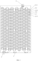
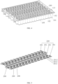
FIG. 1 is a schematic structural diagram of a harness isolation plate provided by an embodiment of the present disclosure. -
FIG. 2 is an enlarged view of A inFIG. 1 . -
FIG. 3 is a bottom view of a harness isolation plate provided by an embodiment of the present disclosure. -
FIG. 4 is a schematic structural diagram of a battery cell and a busbar disposed on a wire harness isolation plate provided by an embodiment of the present disclosure. -
FIG. 5 is a schematic structural diagram of a plurality of busbars provided by an embodiment of the present disclosure. -
FIG. 6 is a schematic structural diagram of another wire harness isolation plate provided by an embodiment of the present disclosure. -
- 100: battery cell; 101: first electrode; 102: second electrode; 200: busbar; 201: connecting element; 2011: first electrode connection portion; 2012: intermediate connection portion; 2013: second electrode connection portion;
- 1: first fixed unit; 11: first fixed plate; 111: battery cell limit slot; 1111: gap; 112: busbar limit slot; 113: rib; 114: first positioning column; 115: first isolation portion; 116: mounting table; 1161: installation hole; 117: second isolation portion; 117: arc-shaped groove;
- 2: second fixed unit; 21: second fixed plate; 22: second positioning column;
- 3: third fixed unit; 31: third fixed plate; 32: buckle;
- 4: fourth fixed unit; 41: fastener;
- 5: output pole conductive bar;
- 6: connector;
- 7: flexible circuit board.
- In the description of the present application, unless otherwise specified and limited, the term "connected to each other", "connected" or "fixed" is to be construed in a broad sense, for example, as fixedly connected, detachably connected, or integrated; mechanically connected or electrically connected; directly connected to each other or indirectly connected to each other via an intermediary; or internally connected between two elements or interactional between two elements. Meanings of the preceding terms in the present application may be understood according to situations.
- In the present application, unless otherwise specified and limited, when a first feature is described as "on" or "below" a second feature, the first feature and the second feature may be in direct contact or be in contact via another feature between the two features instead of being in direct contact. Moreover, when the first feature is described as "on", "above" or "over" the second feature, the first feature is right on, above or over the second feature or the first feature is obliquely on, above or over the second feature, or the first feature is simply at a higher level than the second feature. When the first feature is described as "under", "below" or "underneath" the second feature, the first feature is right under, below or underneath the second feature or the first feature is obliquely under, below or underneath the second feature, or the first feature is simply at a lower level than the second feature.
- An embodiment of the present disclosure provides a battery module, wherein the battery module includes a
battery cell 100, abusbar 200, an output poleconductive bar 5, aflexible circuit board 7, aconnector 6 connected to theflexible circuit board 7, and a wire harness isolation plate. The wire harness isolation plate is arranged on a battery cell module. The battery cell module includes a plurality of thebattery cells 100 and a plurality of thebusbars 200. Any one of thebusbars 200 is configured to connect with at least two of thebattery cells 100 in the battery cell module. Afirst electrode 101 and asecond electrode 102 of thebattery cell 100 are disposed on a same side of thebattery cell 100. - The embodiment of the present disclosure provides the wire harness isolation plate arranged on the battery cell module, and the wire harness isolation plate includes a first fixed unit 1. As shown in
FIG. 1 to FIG. 4 , the first fixed unit 1 includes a first fixedplate 11, a first side of the first fixedplate 11 is configured to position thebusbar 200, and a second side of the first fixedplate 11 is configured to position an end of thebattery cell 100 with an electrode. A part of thefirst electrode 101 and a part of thesecond electrode 102 in each of thebattery cells 100 are exposed from the first fixedplate 11. - As shown in
FIG. 5 , thebusbar 200 includes a plurality of connectingelements 201, the connectingelements 201 are configured to connectadjacent battery cell 100 in series along a first direction. Each of the connectingelements 201 includes a firstelectrode connection portion 2011 connected to thefirst electrode 101 of one of thebattery cells 100, a secondelectrode connection portion 2013 connected to thesecond electrode 102 of another one of thebattery cells 100, and anintermediate connection portion 2012 connected the firstelectrode connection portion 2011 and the secondelectrode connection portion 2013. As shown inFIG. 4 and FIG. 5 , the firstelectrode connection portion 2011 of the connectingelement 201 is connected to thefirst electrode 101 exposed from the first fixedplate 11 of one of theadjacent battery cells 100, and the secondelectrode connection portion 2013 of the connectingelement 201 is connected to thesecond electrode 102 exposed from the first fixedplate 11 of another one of theadjacent battery cells 100. - The first fixed
plate 11 is provided to position all thebattery cells 100 on the battery cell module, so that each of thebattery cells 100 can be installed stably, and a short circuit caused by a contact between thebattery cells 100 can be avoided. The first fixed unit 1 may fixe thebusbar 200 by fixing all of the connectingelements 201 on thebusbar 200, so that thebusbar 200 can be installed stably and avoid a short circuit caused by a contact betweenadjacent busbars 200. Thebusbar 200 and thebattery cell 100 are arranged on respective sides of the first fixedplate 11 to avoid a short circuit caused by a contact among thebusbar 200, and thefirst electrode 101 and thesecond electrode 102 of asame battery cell 100 at the same time. It is unnecessary to apply an additional insulation structure to provide insulation between thebattery cells 100, between thebusbars 200, and between thebusbar 200 and thebattery cell 100, thereby simplifying the structure and reducing the cost. - During a production process, the plurality of the
busbars 200 may be installed on the harness isolation plate through one or more of the first fixed units 1 to define a harness module, and then the harness module and thebattery cells 100 are assembled, which is conducive to make an integrated design. For the battery module, materials may be fed to the harness module, and then the harness module is installed on the battery cell module to define a battery module, which is convenient for installation, improves a grouping efficiency, and makes mass production simple, fast, and efficient. - A part of the
first electrodes 101 and a part of thesecond electrodes 102 of thebattery cell 100 are exposed from the first fixedplate 11, so that the exposedfirst electrodes 101 and the exposedsecond electrodes 102 are connected to adjacent connectingelements 201 in the first direction respectively, so as to achieve a serial connection of twoadjacent battery cells 100 in the first direction. In the embodiment, thefirst electrode 101 is a positive electrode and thesecond electrode 102 is a negative electrode. - The
flexible circuit board 7 is arranged on a side of the first fixedplate 11 away from thebattery cell 100, thereby realizing an isolation between theflexible circuit board 7 and thebattery cell 100. - As shown in
FIG. 1 , the first fixed unit 1 is designed according to an overall size of the battery cell module, an arrangement of the plurality of battery cells in the battery cell module, and the like, so that the first fixed unit 1 defines an integrated structure to be directly installed on the battery cell module, thereby simplifying an assembly process. - Optionally, the
battery cell 100 may be a cylindrical battery cell or a square battery cell. - In the embodiment, as shown in
FIG. 1 , the first direction is an X direction, a second direction is a Y direction, a third direction is a Z direction, and any two of the third direction, the second direction, and the first direction are perpendicular to each other. - The
busbar 200 and the output poleconductive bar 5 are made of conductive materials, and generally may be made of aluminum or copper. - Optionally, as shown in
FIG. 3 , a plurality of batterycell limit slots 111 are defined in the second side of the first fixedplate 11, each of the batterycell limit slots 111 positions a corresponding one of thebattery cells 100, the end of the battery cell with the electrode is correspondingly arranged in the batterycell limit slot 111, and the batterycell limit slot 111 is matched with a shape of the end of a corresponding one of thebattery cells 100 with the electrode. In the embodiment, thebattery cell 100 is the cylindrical battery cell, correspondingly, a notch of the batterycell limit slot 111 is circular or arc shaped, thereby making a wall of the batterycell limit slot 111 is attached to a partial periphery of the cylindrical battery cell. - Optionally, a
gap 1111 is defined in a slot bottom of the batterycell limit slot 111. A part of thesecond electrode 102 is exposed from thegap 1111, and the other part of thesecond electrode 102 is covered by the slot bottom of the batterycell limit slot 111. The slot bottom of the batterycell limit slot 111 is connected with afirst isolation portion 115, a throughhole 1151 is defined in thefirst isolation portion 115, and thefirst electrode 101 is exposed from the throughhole 1151. A short circuit between thefirst electrode 101 and thesecond electrode 102 in asame battery cell 100 can be avoided by providing thefirst isolation portion 115. That is, after the firstelectrode connection portion 2011 of one of the connectingelements 201 is connected to thefirst electrode 101 of the battery cell 100 (hereinafter referred to as a first battery cell for convenience of description) through the throughhole 1151, theintermediate connection portion 2012 of the one of the connectingelements 201 is disposed on a slot bottom wall of thebusbar limit slot 112 corresponding to the first battery cell (that is, the slot bottom wall of thebusbar limit slot 112 separates theintermediate connection portion 2012 of the of the one of the connectingelements 201 from thesecond electrode 102 of the first battery cell), thus the one of the connectingelements 201 is separated from thesecond electrode 102 of the first battery cell. When the secondelectrode connection portion 2013 of the one of the connectingelements 201 is connected to thesecond electrode 102 of a second battery cell, an end of a side of thefirst electrode 101 of the second battery cell close to thesecond electrode 102 is surrounded by a hole wall of the throughhole 1151. Thus, a connection between the secondelectrode connection portion 2013 of the one of the connectingelements 201 and thefirst electrode 101 of the second battery cell is avoided, so as to realize that the connectingelement 201 can not be connected to thefirst electrode 101 and thesecond electrode 102 of the second battery cell at the same time. A shape of thefirst isolation portion 115 is designed according to a structure of thefirst electrode 101 and thesecond electrode 102. For example, when thesecond electrode 102 surrounds a periphery of thefirst electrode 101, and thefirst electrode 101 protrudes from thesecond electrode 102, thefirst isolation portion 115 may be annular and sleeved around thefirst electrode 101. - As shown in
FIG. 2 , the first fixedplate 11 further includes asecond isolation portion 117 arranged on an outer wall of the batterycell limit slot 111. Anarc slot 1171 is defined in thesecond isolation portion 117, and thearc slot 1171 is configured to position adjacent cylindrical battery cells. - Optionally, as shown in
FIG. 3 , when thebattery cell 100 is a cylindrical battery cell, a notch of the batterycell limit slot 111 is circular to match with a shape of thebattery cell 100, and the slot wall is fully attached on a peripheral wall of thebattery cell 100. Alternatively, a gap is defined in the slot wall, a shape of the notch is a circular arc, and a part of the slot wall is attached to a part of the peripheral wall of thebattery cell 100. An internal diameter of the batterycell limit slot 111 is greater than an external diameter of thebattery cell 100. An advantage of this design is that a dimensional tolerance of thebattery cell 100, and a dimensional tolerance defined by thebattery cells 100 stacked may be allowed, so as to maintain relative positions between thebattery cells 100, which provides early guarantee for accurate positioning of thebusbars 200, and ensures a feasibility of assembly. Optionally, a difference between the internal diameter of the batterycell limit slot 111 and the external diameter of thebattery cell 100 ranges from 0.8mm to 1.2mm, for example, it may be 1mm. - Optionally, a plurality of
busbar limit slots 112 are defined in the first side of the first fixedplate 11, and the plurality ofbusbar limit slots 112 are configured to position and limit the plurality ofbusbars 200. The connectingelements 201 of thebusbar 200 is arranged in thebusbar limit slot 112. A part of a main body of the connectingelement 201 is located in the busbar limit slot 112 (for example, theintermediate connection portion 2012 of the connectingelement 201 is located in the busbar limit slot 112). A shape of thebusbar limit slot 112 is matched with a shape of the connectingelement 201, so that a plurality of connectingelements 201 of thebusbar 200 can be limited respectively to achieve a positioning effect of thebusbar 200, thereby improving an installation stability. - A
rib 113 is arranged between adjacentbusbar limit slots 112. Therib 113 is configured to insulate and isolateadjacent busbars 200, thereby ensuring safe electrical clearance and creepage distance maintained between thebusbars 200. - A slotting size of the
busbar limit slot 112 is greater than an overall size of the connectingelement 201. A difference between the slotting size of thebusbar limit slot 112 and the overall size of the connectingelement 201 ranges from 0.3mm to 1mm, which can ensure a normal assembly size of the connectingelement 201 within a tolerance range. - Optionally, the first fixed unit 1 further includes a
first positioning column 114 fixed on a slot bottom of thebusbar limit slot 112, a first mounting hole sleeving thefirst positioning column 114 is defined in thebusbars 200, and an assembly accuracy is improved by positioning thebusbar 200 by thefirst positioning column 114. The first mounting hole is defined in the connectingelement 201. In addition, after positioning thebusbar 200 by thefirst positioning column 114, thefirst positioning column 114 is hot melted to fix thebusbar 200 on the first fixedplate 11. Thefirst positioning column 114 is a cylindrical column, which is convenient for installation. An external diameter of the cylindrical column ranges from 2mm to 5mm, which ensures a sufficient structural strength. In other embodiments, the first fixed unit 1 may also include a positioning hole defined in a slot bottom of thebusbar limit slot 112, and a mounting column is provided on the busbar 200 (in the embodiment, on the connecting element 201). As such, the positioning hole is sleeved on the mounting column, and thebusbar 200 is positioned by the positioning hole. - Optionally, as shown in
FIG. 1 , the wire harness isolation plate further includes a second fixed unit 2, and the second fixed unit 2 is connected to the first fixedplate 11. The second fixed unit 2 is configured to fix the output poleconductive bar 5 connected to thebusbar 200. The second fixed unit 2 is configured to fix the output poleconductive bar 5. In the embodiment, the wire harness isolation plate includes two second fixed units 2, the two second fixed units 2 are connected to respective ends of the first fixedplate 11 along the first direction. One of two output poleconductive bars 5 is connected to one of the two second fixed plates 2, and the other of the two output poleconductive bars 5 is connected to the other of the two second fixed plates 2. Thebattery cell 100 and thebusbar 200 are arranged on respective sides of the first fixedplate 11 along the second direction. - Optionally, the second fixed unit 2 includes a second fixed
plate 21 connected to the first fixedplate 11, the output poleconductive bar 5 is fixed on the second fixedplates 21, and the second fixedplate 21 is configured to support the output poleconductive bar 5. The second fixed unit 2 includes asecond positioning column 22 fixed on the second fixedplate 21. A second mounting hole configured to sleeve thesecond positioning column 22 is defined in the output poleconductive bar 5. Thesecond positioning column 22 positions the output poleconductive bar 5 to improve an assembly accuracy. In addition, after thesecond positioning column 22 position the output poleconductive bar 5, thesecond positioning column 22 is hot melted, and the output poleconductive bar 5 is fixed on the second fixedplate 21 through thesecond positioning column 22. Thesecond positioning column 22 is cylindrical column, which is convenient for installation. An external diameter of the cylindrical column ranges from 2 mm to 5 mm, which ensures sufficient structural strength. - As shown in
FIG. 1 , the wire harness isolation plate may be provided with a plurality offirst positioning columns 114 and a plurality ofsecond positioning columns 22. The spaces among the plurality offirst positioning columns 114 and the spaces among the plurality ofsecond positioning columns 22 may be determined according to an actual situation, which is not limited herein. - Optionally, the wire harness isolation board further includes a third
fixed unit 3 connected to the first fixedplate 11. The thirdfixed unit 3 is configured to fix theconnector 6, as shown inFIG. 6 . Theflexible circuit board 7 is fixed on the thirdfixed unit 3 by theconnector 6, and theflexible circuit board 7 is arranged on a side of the first fixedplate 11 away from thebattery cell 100. The thirdfixed unit 3 is configured to fix theconnector 6, so that theflexible circuit board 7 is fixed on the thirdfixed unit 3. In the embodiment, the wire harness isolation board includes three thirdfixed units 3, and the three thirdfixed units 3 are connected to the second fixed unit 2. Each thirdfixed unit 3 may fix oneflexible circuit board 7 through theconnector 6. The three thirdfixed units 3 are spaced along a third direction. In other embodiments, the number of the thirdfixed units 3 may be determined according to the number of theflexible circuit boards 7. Optionally, the thirdfixed unit 3 may be fixed on the second fixed unit 2 on either side of the first fixedplate 11 or may also be fixed on the first fixedplate 11. - Optionally, each third
fixed unit 3 includes a thirdfixed plate 31 fixed on the first fixedplate 11, and theconnector 6 is clamped to the thirdfixed plates 31. In the embodiment, the thirdfixed plate 31 is directly connected to the second fixedplate 21, and is indirectly connected to the first fixedplate 11 through the second fixedplate 21. The thirdfixed plate 31 is perpendicular to the first fixedplate 11. Theconnector 6 is clamped to the thirdfixed plate 31, and theconnector 6 is connected to a side of the thirdfixed plate 31 away from thebattery cell 100. In other embodiments, the thirdfixed plate 31 may also be disposed in an included angle with the first fixedplate 11. As shown inFIG. 1 , the thirdfixed plate 31 is provided with a structure of abuckle 32, and theconnector 6 are clamped to the thirdfixed plate 31 through thebuckle 32, so as to avoid fasteners such as bolts, resulting in easier installation. - Optionally, the first fixed
plate 11 is connected to a fourth fixedplate 4, and the output poleconductive bar 5 is extend to the fourth fixedplate 4. In the embodiment, the fourth fixedplate 4 is directly and fixedly connected to the second fixedplate 21, and is indirectly connected to the first fixedplate 11 through the second fixedplate 21. The fourth fixedplate 4 is embedded with afastener 41. In the embodiment, thefastener 41 is a nut. The battery modules may be connected in series by a threaded connection that a screw is threaded through thefastener 41 embedded in the fourth fixedplate 4, and the connection is convenient and reliable, thereby reducing the assembly process and improving the production efficiency. The fourth fixedplate 4 may be a plastic plate, and thefastener 41 may be molded on the fourth fixedplate 4. In other embodiments, thefastener 41 may be a stud. - Optionally, the first fixed
plate 11 is provided with aninstallation hole 1161, and theinstallation hole 1161 is configured to fix an upper cover of the battery module. The upper cover may be directly riveted with theinstallation hole 1161 to realize the fixing of the upper cover. This fixing is not only economical, but also fast and efficient. Optionally, after installing the wire harness isolation plate and the battery cell module, the upper cover of the battery module is fixed to the wire harness isolation plate by installing the fasteners on the installation holes 1161. As shown inFIG. 1 , the first fixedplate 11 is provided with a mountingplatform 116, and theinstallation hole 1161 is arranged on the mountingplatform 116. - Optionally, the first fixed unit 1, the second fixed unit 2, and the third
fixed unit 3 are integrated. In the embodiment, the first fixedplate 11, the second fixedplate 21, the thirdfixed plate 31 and the fourth fixedplate 4 are integrated. A material of the wire harness isolation plate may be plastic, such as a raw material of polycarbonate (PC) and acrylonitrile butadiene styrene (ABS).
Claims (16)
- A wire harness isolation plate, wherein the wire harness isolation plate is disposed on a battery cell module, the battery cell module comprises a plurality of battery cells (100) and a plurality of busbars (200), each of the busbars (200) is configured to connect with at least two battery cells (100) in the battery cell module, and a first electrode (101) and a second electrode (102) of each of the battery cells (100) are disposed on a same side of the battery cell (100); wherein the wire harness isolation plate comprises a first fixed unit (1), the first fixed unit (1) comprises a first fixed plate (11), a first side of the first fixed plate (11) is configured to position the busbar (200), a second side of the first fixed plate (11) is configured to position an end of the battery cell (100) provided with the first electrode (101) and the second electrode (102) and to expose a part of the first electrode (101) and a part of the second electrode (102) of the battery cell (100).
- The wire harness isolation plate of claim 1, wherein a plurality of battery cell limit slots (111) are defined on the second side of the first fixed plate (11), each of the battery cell limit slots (111) is configured to position a corresponding one of the battery cells (100), and further to position an end of the corresponding one of the battery cells (100) provided with the first electrode (101) and the second electrode (102), and a notch shape of the battery cell limit slot (111) is matched with a shape of an end of the battery cell (100) provided with the first electrode (101) and the second electrode (102).
- The wire harness isolation plate of claim 2, wherein a gap (1111) is defined on a bottom of the battery cell limit slot (111), a part of the second electrode (102) of the battery cell (100) disposed in the battery cell limit slot (111) is exposed from the gap (1111), wherein the bottom of the battery cell limit slot (111) is connected with a first isolation portion (115), a through hole (1151) is defined on the first isolation portion (115), and the through hole (1151) is configured to expose the first electrode (101) of the battery cell (100) disposed in the battery cell limit slot (111).
- The wire harness isolation plate of claim 2, wherein the battery cell (100) is a cylindrical battery cell, and a shape of the battery cell limit slot (111) is circular or arcuate.
- The wire harness isolation plate of claim 4, wherein an internal diameter of the battery cell limit slot (111) is greater than an external diameter of the battery cell (100).
- The wire harness isolation plate of claim 1, wherein a plurality of busbar limit slots (112) are defined on a first side of the first fixed plate (11), and each of the plurality of busbar limit slots (112) is configured to position the busbar (200).
- The wire harness isolation plate of claim 6, wherein a rib (113) is arranged between adjacent busbar limit slots (112).
- The wire harness isolation plate of claim 6, wherein the first fixed unit (1) further comprise a first positioning column (114) disposed on a bottom of the busbar limit slot (112), and a first mounting hole is defined on the busbar (200) for sleeving on the first positioning column (114); or
the first fixed unit (1) further comprises a positioning hole defined on the bottom of the busbar limit slot (112), the busbar (200) is provided with a mounting column, and the positioning hole is configured to be sleeved on the mounting column. - The wire harness isolation plate of any one of claim 1 to claim 8, further comprising a second fixed unit (2), wherein the second fixed unit (2) is connected to the first fixed plate (11), and the second fixed unit (2) is configured to fix an output pole conductive bar (5) connected to the plurality of busbars (200).
- The wire harness isolation plate of claim 9, wherein the second fixed unit (2) comprises a second fixed plate (21) connected to the first fixed plate (11), the second fixed plate (21) is configured to fix the output pole conductive bar (5), the second fixed unit (2) further comprises a second positioning column (22) fixed on the second fixed plate (21), and a second mounting hole is defined on the output pole conductive bar (5) for sleeving on the second positioning column (22).
- The wire harness isolation plate of any one of claim 1 to claim 8, further comprising a third fixed unit (3), wherein the third fixed unit (3) is connected to the first fixed plate (11), the third fixed unit (3) is configured to fix a connector (6), and the third fixed unit (3) is configured to fix a flexible circuit board (7) by the connector (6), wherein a side of the first fixed plate (11) away from the battery cell (100) is configured to dispose the flexible circuit board (7).
- The wire harness isolation plate of claim 11, wherein the third fixed units (3) comprises a third fixed plate (31) fixed on the first fixed plate (11), and the third fixed plate (31) is configured to clamp the connector (6).
- The wire harness isolation plate of any one of claim 1 to claim 8, wherein the first fixed plate (11) is connected with a fourth fixed plate (4), the output pole conductive bar (5) connected with the plurality of busbars (200) is extended to the fourth fixed plate (4), and the fourth fixed plate (4) is embedded with a fastener (41).
- The wire harness isolation plate of any one of claim 1 to claim 8, wherein the first fixed plate (11) is provided with an installation hole (1161), and the installation holes (1161) are configured to fix an upper cover of a battery module.
- The wire harness isolation plate of any one of claim 1 to claim 8, further comprising:a second fixed unit (2), wherein the second fixed unit (2) is connected to the first fixed plate (11), the second fixed unit (2) is configured to fix an output pole conductive bar (5) connected to the plurality of busbars (200); anda third fixed unit (3), wherein the third fixed unit (3) is connected to the first fixed plate (11), the third fixed unit (3) is configured to fix a connector (6), the third fixed unit (3) is further configured to fix a flexible circuit board (7) by the connector (6), and a side of the first fixed plate (11) away from the battery cell (100) is configured to dispose the flexible circuit board (7);wherein the first fixed unit (1), the second fixed unit (2) and the third fixed units (3) are integrated.
- A battery module, comprising the wire harness isolation plate of any one of claim 1 to claim 15, the battery cell module, the busbar (200), an output pole conductive bar (5), a flexible circuit board (7), and a connector (6), wherein the battery cell module, the busbar (200), the output pole conductive bar (5), the flexible circuit board (7), and the connector (6) are arranged on the wire harness isolation plate.
Applications Claiming Priority (2)
| Application Number | Priority Date | Filing Date | Title |
|---|---|---|---|
| CN202220278058.2U CN217158501U (en) | 2022-02-11 | 2022-02-11 | Wiring harness isolation plate and battery module |
| PCT/CN2022/125979 WO2023151307A1 (en) | 2022-02-11 | 2022-10-18 | Wire harness isolation plate and battery module |
Publications (2)
| Publication Number | Publication Date |
|---|---|
| EP4254630A1 true EP4254630A1 (en) | 2023-10-04 |
| EP4254630A4 EP4254630A4 (en) | 2024-12-25 |
Family
ID=82690040
Family Applications (1)
| Application Number | Title | Priority Date | Filing Date |
|---|---|---|---|
| EP22818607.8A Pending EP4254630A4 (en) | 2022-02-11 | 2022-10-18 | WIRE HARNESS INSULATION PLATE AND BATTERY MODULE |
Country Status (4)
| Country | Link |
|---|---|
| US (1) | US12525679B2 (en) |
| EP (1) | EP4254630A4 (en) |
| CN (1) | CN217158501U (en) |
| WO (1) | WO2023151307A1 (en) |
Families Citing this family (11)
| Publication number | Priority date | Publication date | Assignee | Title |
|---|---|---|---|---|
| CN217158579U (en) | 2022-02-11 | 2022-08-09 | 湖北亿纬动力有限公司 | Insulating support and battery module |
| CN217158501U (en) * | 2022-02-11 | 2022-08-09 | 湖北亿纬动力有限公司 | Wiring harness isolation plate and battery module |
| USD1115701S1 (en) * | 2022-07-08 | 2026-03-03 | Eve Energy Co., Ltd. | Voltage and temperature collecting assembly for power battery |
| CN218569141U (en) * | 2022-09-30 | 2023-03-03 | 湖北亿纬动力有限公司 | Module support and power battery module |
| AT526615B1 (en) * | 2022-10-25 | 2024-09-15 | Miba Battery Systems Gmbh | Cell module with rechargeable cells |
| CN116742253B (en) * | 2023-05-31 | 2025-07-25 | 福建时代星云科技有限公司 | A symmetrical distributed integrated energy storage battery module |
| CN116632449A (en) * | 2023-05-31 | 2023-08-22 | 福建时代星云科技有限公司 | Wire harness isolation plate structure and battery module |
| CN116666859A (en) * | 2023-06-07 | 2023-08-29 | 福建时代星云科技有限公司 | An anti-vibration and shock module structure |
| CN220604906U (en) * | 2023-08-04 | 2024-03-15 | 武汉亿纬储能有限公司 | A battery module and battery pack |
| WO2025076982A1 (en) * | 2023-10-13 | 2025-04-17 | 惠州亿纬锂能股份有限公司 | Battery module and electric device |
| CN117293489B (en) * | 2023-10-13 | 2026-06-30 | 惠州亿纬锂能股份有限公司 | Battery module and electric equipment |
Family Cites Families (5)
| Publication number | Priority date | Publication date | Assignee | Title |
|---|---|---|---|---|
| JP4127501B2 (en) | 2002-11-19 | 2008-07-30 | 松下電器産業株式会社 | Battery connection structure, battery module, and battery pack |
| CN210129548U (en) * | 2019-09-06 | 2020-03-06 | 华霆(合肥)动力技术有限公司 | Battery module and cover plate |
| CN213242865U (en) * | 2020-11-16 | 2021-05-18 | 江苏塔菲尔动力系统有限公司 | Flexible circuit board assembly for battery module and battery module thereof |
| CN113937404B (en) | 2021-09-30 | 2023-07-14 | 蜂巢能源科技有限公司 | Cylindrical battery module |
| CN217158501U (en) | 2022-02-11 | 2022-08-09 | 湖北亿纬动力有限公司 | Wiring harness isolation plate and battery module |
-
2022
- 2022-02-11 CN CN202220278058.2U patent/CN217158501U/en active Active
- 2022-10-18 EP EP22818607.8A patent/EP4254630A4/en active Pending
- 2022-10-18 WO PCT/CN2022/125979 patent/WO2023151307A1/en not_active Ceased
- 2022-10-18 US US18/002,865 patent/US12525679B2/en active Active
Also Published As
| Publication number | Publication date |
|---|---|
| EP4254630A4 (en) | 2024-12-25 |
| US20240113378A1 (en) | 2024-04-04 |
| CN217158501U (en) | 2022-08-09 |
| US12525679B2 (en) | 2026-01-13 |
| WO2023151307A1 (en) | 2023-08-17 |
Similar Documents
| Publication | Publication Date | Title |
|---|---|---|
| US12525679B2 (en) | Wire harness isolation plate including limit structure and battery module | |
| EP4254646A1 (en) | Insulating support and battery module | |
| CN220138658U (en) | Bus components and battery assembly | |
| JP6404473B2 (en) | Assembled battery | |
| CN114447528B (en) | Busbar and group battery | |
| EP4068486B1 (en) | Battery pack | |
| EP3933952B1 (en) | Battery module, battery pack and device | |
| CN206639834U (en) | A kind of battery modules | |
| WO2024041500A1 (en) | Busbar support assembly, power battery, and vehicle | |
| CN206742347U (en) | A battery module | |
| CN113097654A (en) | Battery module | |
| EP2581964A1 (en) | Battery pack | |
| CN116864925A (en) | Battery collection connecting assembly, battery module and battery pack | |
| CN215600653U (en) | Car wiring harness connector convenient to dismouting | |
| CN217009482U (en) | Busbar and battery module | |
| CN222381014U (en) | Integrated busbar, battery module and battery pack | |
| EP4366142A1 (en) | Electric motor inverter | |
| CN116802891A (en) | Cell heating components, battery modules and vehicles | |
| EP4513619A1 (en) | Ccs assembly and battery module | |
| EP4614663A1 (en) | Battery management system and battery pack | |
| US20250300246A1 (en) | Battery pack | |
| CN113921972B (en) | Portable power battery package module support that trades and power battery package | |
| CN222581335U (en) | Battery module | |
| CN220233399U (en) | Battery cover plate assembly, battery core and battery module | |
| CN222868002U (en) | Battery sampler, battery pack and electric equipment |
Legal Events
| Date | Code | Title | Description |
|---|---|---|---|
| STAA | Information on the status of an ep patent application or granted ep patent |
Free format text: STATUS: UNKNOWN |
|
| STAA | Information on the status of an ep patent application or granted ep patent |
Free format text: STATUS: THE INTERNATIONAL PUBLICATION HAS BEEN MADE |
|
| PUAI | Public reference made under article 153(3) epc to a published international application that has entered the european phase |
Free format text: ORIGINAL CODE: 0009012 |
|
| STAA | Information on the status of an ep patent application or granted ep patent |
Free format text: STATUS: REQUEST FOR EXAMINATION WAS MADE |
|
| 17P | Request for examination filed |
Effective date: 20221216 |
|
| AK | Designated contracting states |
Kind code of ref document: A1 Designated state(s): AL AT BE BG CH CY CZ DE DK EE ES FI FR GB GR HR HU IE IS IT LI LT LU LV MC ME MK MT NL NO PL PT RO RS SE SI SK SM TR |
|
| A4 | Supplementary search report drawn up and despatched |
Effective date: 20241126 |
|
| RIC1 | Information provided on ipc code assigned before grant |
Ipc: H01M 50/213 20210101ALI20241120BHEP Ipc: H01M 50/503 20210101ALI20241120BHEP Ipc: H01M 50/507 20210101ALI20241120BHEP Ipc: H01M 50/258 20210101AFI20241120BHEP |
|
| DAV | Request for validation of the european patent (deleted) | ||
| DAX | Request for extension of the european patent (deleted) |