EP4254579A1 - Secondary battery - Google Patents
Secondary battery Download PDFInfo
- Publication number
- EP4254579A1 EP4254579A1 EP23153647.5A EP23153647A EP4254579A1 EP 4254579 A1 EP4254579 A1 EP 4254579A1 EP 23153647 A EP23153647 A EP 23153647A EP 4254579 A1 EP4254579 A1 EP 4254579A1
- Authority
- EP
- European Patent Office
- Prior art keywords
- cap
- secondary battery
- cylindrical case
- terminal plate
- plate
- Prior art date
- Legal status (The legal status is an assumption and is not a legal conclusion. Google has not performed a legal analysis and makes no representation as to the accuracy of the status listed.)
- Pending
Links
Images

Classifications
-
- H—ELECTRICITY
- H01—ELECTRIC ELEMENTS
- H01M—PROCESSES OR MEANS, e.g. BATTERIES, FOR THE DIRECT CONVERSION OF CHEMICAL ENERGY INTO ELECTRICAL ENERGY
- H01M50/00—Constructional details or processes of manufacture of the non-active parts of electrochemical cells other than fuel cells, e.g. hybrid cells
- H01M50/50—Current conducting connections for cells or batteries
- H01M50/502—Interconnectors for connecting terminals of adjacent batteries; Interconnectors for connecting cells outside a battery casing
-
- H—ELECTRICITY
- H01—ELECTRIC ELEMENTS
- H01M—PROCESSES OR MEANS, e.g. BATTERIES, FOR THE DIRECT CONVERSION OF CHEMICAL ENERGY INTO ELECTRICAL ENERGY
- H01M50/00—Constructional details or processes of manufacture of the non-active parts of electrochemical cells other than fuel cells, e.g. hybrid cells
- H01M50/10—Primary casings; Jackets or wrappings
- H01M50/102—Primary casings; Jackets or wrappings characterised by their shape or physical structure
- H01M50/107—Primary casings; Jackets or wrappings characterised by their shape or physical structure having curved cross-section, e.g. round or elliptic
-
- H—ELECTRICITY
- H01—ELECTRIC ELEMENTS
- H01M—PROCESSES OR MEANS, e.g. BATTERIES, FOR THE DIRECT CONVERSION OF CHEMICAL ENERGY INTO ELECTRICAL ENERGY
- H01M10/00—Secondary cells; Manufacture thereof
- H01M10/04—Construction or manufacture in general
- H01M10/0422—Cells or battery with cylindrical casing
-
- H—ELECTRICITY
- H01—ELECTRIC ELEMENTS
- H01M—PROCESSES OR MEANS, e.g. BATTERIES, FOR THE DIRECT CONVERSION OF CHEMICAL ENERGY INTO ELECTRICAL ENERGY
- H01M10/00—Secondary cells; Manufacture thereof
- H01M10/05—Accumulators with non-aqueous electrolyte
- H01M10/052—Li-accumulators
-
- H—ELECTRICITY
- H01—ELECTRIC ELEMENTS
- H01M—PROCESSES OR MEANS, e.g. BATTERIES, FOR THE DIRECT CONVERSION OF CHEMICAL ENERGY INTO ELECTRICAL ENERGY
- H01M10/00—Secondary cells; Manufacture thereof
- H01M10/05—Accumulators with non-aqueous electrolyte
- H01M10/058—Construction or manufacture
- H01M10/0585—Construction or manufacture of accumulators having only flat construction elements, i.e. flat positive electrodes, flat negative electrodes and flat separators
-
- H—ELECTRICITY
- H01—ELECTRIC ELEMENTS
- H01M—PROCESSES OR MEANS, e.g. BATTERIES, FOR THE DIRECT CONVERSION OF CHEMICAL ENERGY INTO ELECTRICAL ENERGY
- H01M50/00—Constructional details or processes of manufacture of the non-active parts of electrochemical cells other than fuel cells, e.g. hybrid cells
- H01M50/10—Primary casings; Jackets or wrappings
- H01M50/147—Lids or covers
- H01M50/148—Lids or covers characterised by their shape
- H01M50/152—Lids or covers characterised by their shape for cells having curved cross-section, e.g. round or elliptic
-
- H—ELECTRICITY
- H01—ELECTRIC ELEMENTS
- H01M—PROCESSES OR MEANS, e.g. BATTERIES, FOR THE DIRECT CONVERSION OF CHEMICAL ENERGY INTO ELECTRICAL ENERGY
- H01M50/00—Constructional details or processes of manufacture of the non-active parts of electrochemical cells other than fuel cells, e.g. hybrid cells
- H01M50/10—Primary casings; Jackets or wrappings
- H01M50/147—Lids or covers
- H01M50/155—Lids or covers characterised by the material
- H01M50/157—Inorganic material
- H01M50/159—Metals
-
- H—ELECTRICITY
- H01—ELECTRIC ELEMENTS
- H01M—PROCESSES OR MEANS, e.g. BATTERIES, FOR THE DIRECT CONVERSION OF CHEMICAL ENERGY INTO ELECTRICAL ENERGY
- H01M50/00—Constructional details or processes of manufacture of the non-active parts of electrochemical cells other than fuel cells, e.g. hybrid cells
- H01M50/10—Primary casings; Jackets or wrappings
- H01M50/147—Lids or covers
- H01M50/166—Lids or covers characterised by the methods of assembling casings with lids
- H01M50/167—Lids or covers characterised by the methods of assembling casings with lids by crimping
-
- H—ELECTRICITY
- H01—ELECTRIC ELEMENTS
- H01M—PROCESSES OR MEANS, e.g. BATTERIES, FOR THE DIRECT CONVERSION OF CHEMICAL ENERGY INTO ELECTRICAL ENERGY
- H01M50/00—Constructional details or processes of manufacture of the non-active parts of electrochemical cells other than fuel cells, e.g. hybrid cells
- H01M50/10—Primary casings; Jackets or wrappings
- H01M50/147—Lids or covers
- H01M50/166—Lids or covers characterised by the methods of assembling casings with lids
- H01M50/171—Lids or covers characterised by the methods of assembling casings with lids using adhesives or sealing agents
-
- H—ELECTRICITY
- H01—ELECTRIC ELEMENTS
- H01M—PROCESSES OR MEANS, e.g. BATTERIES, FOR THE DIRECT CONVERSION OF CHEMICAL ENERGY INTO ELECTRICAL ENERGY
- H01M50/00—Constructional details or processes of manufacture of the non-active parts of electrochemical cells other than fuel cells, e.g. hybrid cells
- H01M50/10—Primary casings; Jackets or wrappings
- H01M50/172—Arrangements of electric connectors penetrating the casing
- H01M50/174—Arrangements of electric connectors penetrating the casing adapted for the shape of the cells
- H01M50/176—Arrangements of electric connectors penetrating the casing adapted for the shape of the cells for prismatic or rectangular cells
-
- H—ELECTRICITY
- H01—ELECTRIC ELEMENTS
- H01M—PROCESSES OR MEANS, e.g. BATTERIES, FOR THE DIRECT CONVERSION OF CHEMICAL ENERGY INTO ELECTRICAL ENERGY
- H01M50/00—Constructional details or processes of manufacture of the non-active parts of electrochemical cells other than fuel cells, e.g. hybrid cells
- H01M50/10—Primary casings; Jackets or wrappings
- H01M50/172—Arrangements of electric connectors penetrating the casing
- H01M50/174—Arrangements of electric connectors penetrating the casing adapted for the shape of the cells
- H01M50/179—Arrangements of electric connectors penetrating the casing adapted for the shape of the cells for cells having curved cross-section, e.g. round or elliptic
-
- H—ELECTRICITY
- H01—ELECTRIC ELEMENTS
- H01M—PROCESSES OR MEANS, e.g. BATTERIES, FOR THE DIRECT CONVERSION OF CHEMICAL ENERGY INTO ELECTRICAL ENERGY
- H01M50/00—Constructional details or processes of manufacture of the non-active parts of electrochemical cells other than fuel cells, e.g. hybrid cells
- H01M50/10—Primary casings; Jackets or wrappings
- H01M50/183—Sealing members
-
- H—ELECTRICITY
- H01—ELECTRIC ELEMENTS
- H01M—PROCESSES OR MEANS, e.g. BATTERIES, FOR THE DIRECT CONVERSION OF CHEMICAL ENERGY INTO ELECTRICAL ENERGY
- H01M50/00—Constructional details or processes of manufacture of the non-active parts of electrochemical cells other than fuel cells, e.g. hybrid cells
- H01M50/10—Primary casings; Jackets or wrappings
- H01M50/183—Sealing members
- H01M50/184—Sealing members characterised by their shape or structure
-
- H—ELECTRICITY
- H01—ELECTRIC ELEMENTS
- H01M—PROCESSES OR MEANS, e.g. BATTERIES, FOR THE DIRECT CONVERSION OF CHEMICAL ENERGY INTO ELECTRICAL ENERGY
- H01M50/00—Constructional details or processes of manufacture of the non-active parts of electrochemical cells other than fuel cells, e.g. hybrid cells
- H01M50/10—Primary casings; Jackets or wrappings
- H01M50/183—Sealing members
- H01M50/186—Sealing members characterised by the disposition of the sealing members
-
- H—ELECTRICITY
- H01—ELECTRIC ELEMENTS
- H01M—PROCESSES OR MEANS, e.g. BATTERIES, FOR THE DIRECT CONVERSION OF CHEMICAL ENERGY INTO ELECTRICAL ENERGY
- H01M50/00—Constructional details or processes of manufacture of the non-active parts of electrochemical cells other than fuel cells, e.g. hybrid cells
- H01M50/10—Primary casings; Jackets or wrappings
- H01M50/183—Sealing members
- H01M50/186—Sealing members characterised by the disposition of the sealing members
- H01M50/188—Sealing members characterised by the disposition of the sealing members the sealing members being arranged between the lid and terminal
-
- H—ELECTRICITY
- H01—ELECTRIC ELEMENTS
- H01M—PROCESSES OR MEANS, e.g. BATTERIES, FOR THE DIRECT CONVERSION OF CHEMICAL ENERGY INTO ELECTRICAL ENERGY
- H01M50/00—Constructional details or processes of manufacture of the non-active parts of electrochemical cells other than fuel cells, e.g. hybrid cells
- H01M50/30—Arrangements for facilitating escape of gases
- H01M50/342—Non-re-sealable arrangements
-
- H—ELECTRICITY
- H01—ELECTRIC ELEMENTS
- H01M—PROCESSES OR MEANS, e.g. BATTERIES, FOR THE DIRECT CONVERSION OF CHEMICAL ENERGY INTO ELECTRICAL ENERGY
- H01M50/00—Constructional details or processes of manufacture of the non-active parts of electrochemical cells other than fuel cells, e.g. hybrid cells
- H01M50/30—Arrangements for facilitating escape of gases
- H01M50/342—Non-re-sealable arrangements
- H01M50/3425—Non-re-sealable arrangements in the form of rupturable membranes or weakened parts, e.g. pierced with the aid of a sharp member
-
- H—ELECTRICITY
- H01—ELECTRIC ELEMENTS
- H01M—PROCESSES OR MEANS, e.g. BATTERIES, FOR THE DIRECT CONVERSION OF CHEMICAL ENERGY INTO ELECTRICAL ENERGY
- H01M50/00—Constructional details or processes of manufacture of the non-active parts of electrochemical cells other than fuel cells, e.g. hybrid cells
- H01M50/50—Current conducting connections for cells or batteries
- H01M50/543—Terminals
- H01M50/547—Terminals characterised by the disposition of the terminals on the cells
- H01M50/55—Terminals characterised by the disposition of the terminals on the cells on the same side of the cell
-
- H—ELECTRICITY
- H01—ELECTRIC ELEMENTS
- H01M—PROCESSES OR MEANS, e.g. BATTERIES, FOR THE DIRECT CONVERSION OF CHEMICAL ENERGY INTO ELECTRICAL ENERGY
- H01M50/00—Constructional details or processes of manufacture of the non-active parts of electrochemical cells other than fuel cells, e.g. hybrid cells
- H01M50/50—Current conducting connections for cells or batteries
- H01M50/543—Terminals
- H01M50/552—Terminals characterised by their shape
- H01M50/553—Terminals adapted for prismatic, pouch or rectangular cells
- H01M50/557—Plate-shaped terminals
-
- H—ELECTRICITY
- H01—ELECTRIC ELEMENTS
- H01M—PROCESSES OR MEANS, e.g. BATTERIES, FOR THE DIRECT CONVERSION OF CHEMICAL ENERGY INTO ELECTRICAL ENERGY
- H01M50/00—Constructional details or processes of manufacture of the non-active parts of electrochemical cells other than fuel cells, e.g. hybrid cells
- H01M50/50—Current conducting connections for cells or batteries
- H01M50/543—Terminals
- H01M50/552—Terminals characterised by their shape
- H01M50/559—Terminals adapted for cells having curved cross-section, e.g. round, elliptic or button cells
-
- H—ELECTRICITY
- H01—ELECTRIC ELEMENTS
- H01M—PROCESSES OR MEANS, e.g. BATTERIES, FOR THE DIRECT CONVERSION OF CHEMICAL ENERGY INTO ELECTRICAL ENERGY
- H01M50/00—Constructional details or processes of manufacture of the non-active parts of electrochemical cells other than fuel cells, e.g. hybrid cells
- H01M50/10—Primary casings; Jackets or wrappings
- H01M50/183—Sealing members
- H01M50/19—Sealing members characterised by the material
- H01M50/193—Organic material
-
- Y—GENERAL TAGGING OF NEW TECHNOLOGICAL DEVELOPMENTS; GENERAL TAGGING OF CROSS-SECTIONAL TECHNOLOGIES SPANNING OVER SEVERAL SECTIONS OF THE IPC; TECHNICAL SUBJECTS COVERED BY FORMER USPC CROSS-REFERENCE ART COLLECTIONS [XRACs] AND DIGESTS
- Y02—TECHNOLOGIES OR APPLICATIONS FOR MITIGATION OR ADAPTATION AGAINST CLIMATE CHANGE
- Y02E—REDUCTION OF GREENHOUSE GAS [GHG] EMISSIONS, RELATED TO ENERGY GENERATION, TRANSMISSION OR DISTRIBUTION
- Y02E60/00—Enabling technologies; Technologies with a potential or indirect contribution to GHG emissions mitigation
- Y02E60/10—Energy storage using batteries
Definitions
- the present disclosure relates to a secondary battery.
- Lithium ion secondary batteries are used as power sources for hybrid vehicles or electric vehicles as well as portable electronic devices because of, for example, a high operating voltage and a high energy density per unit weight.
- Secondary batteries may be classified as cylindrical, prismatic, or pouch-shaped secondary batteries according to shape.
- a cylindrical secondary battery generally includes a cylindrical case, a cylindrical electrode assembly that is coupled to the case, an electrolyte (optional) that is injected into the case to enable movement of lithium ions, and a cap assembly that is coupled to one side of the case to prevent leakage of the electrolyte and prevents separation of the electrode assembly.
- the present disclosure provides a secondary battery capable of facilitating welding with an external device.
- a secondary battery includes: a cylindrical case; an electrode assembly accommodated in the cylindrical case; and a cap assembly sealing the cylindrical case and including a cap-up electrically connected to a positive electrode of the electrode assembly, a terminal plate coupled to an upper portion of the cap-up and electrically connected to a negative electrode of the electrode assembly, and a first insulating gasket interposed between the cap-up and the terminal plate.
- the terminal plate may be electrically connected to the cylindrical case.
- the cylindrical case may include a beading part recessed inwardly at the lower part of the cap assembly and a crimping part bent inwardly at the upper part of the cap assembly, and the crimping part covers a portion of the terminal plate.
- the terminal plate may be located above the edge of the cap-up and may expose a central portion protruding upward from the cap-up.
- the area of the terminal plate may correspond to the area of the edge of the cap-up.
- the first insulating gasket may be located between the edge of the cap-up and the terminal plate, and the area of the first insulating gasket may be larger than that of the terminal plate.
- the first insulating gasket may include an extension part extending upward and covering a side surface of the terminal plate.
- the secondary battery may further include a second insulating gasket interposed between the cap-up and the cylindrical case.
- the secondary battery may further include: a vent plate installed under the cap-up and provided with a notch; a cap-down installed under the vent plate and provided with a plurality of through holes; and an insulator interposed between the vent plate and the cap-down.
- the cylindrical case may include a notch provided on a bottom surface.
- first, second, etc. may be used herein to describe various members, elements, regions, layers and/or sections, these members, elements, regions, layers and/or sections should not be limited by these terms. These terms are only used to distinguish one member, element, region, layer and/or section from another. Thus, for example, a first member, a first element, a first region, a first layer and/or a first section discussed below could be termed a second member, a second element, a second region, a second layer and/or a second section without departing from the teachings of the present invention.
- spatially relative terms such as “beneath,” “below,” “lower,” “above,” “upper,” and the like, may be used herein for ease of description to describe one element or feature's relationship to another element(s) or feature(s) as illustrated in the figures. It will be understood that the spatially relative terms are intended to encompass different orientations of the device in use or operation in addition to the orientation depicted in the figures. For example, if the element or feature in the figures is turned over, elements described as “below” or “beneath” other elements or features would then be oriented “on” or “above” the other elements or features. Thus, the term “below” can encompass both an orientation of above and below.
- FIG. 1 is a perspective view illustrating a secondary battery according to an embodiment of the present disclosure.
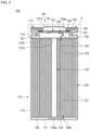
- FIG. 2 is a cross-sectional view illustrating a secondary battery according to an embodiment of the present disclosure.
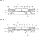
- FIGS. 3A and 3B are enlarged cross-sectional views of portion A of FIG. 2 .
- the secondary battery 100 includes a cylindrical case 110, an electrode assembly 120, and a cap assembly 130.
- the cap assembly 130 may include or be referred to as a cap, a cap group, a cap assembly, a cover, or a lid.
- the cylindrical case 110 may include a substantially circular bottom portion 111 and a sidewall 112 extending a predetermined length upward from the bottom portion 111.
- the cylindrical case 110 may include or be referred to as a can, an exterior material, or a housing.
- the top of the cylindrical case 110 may be opened. Therefore, during the assembly process of the secondary battery, the electrode assembly 120 may be integrated into one structure and inserted into the cylindrical case 110. Of course, an electrolyte may be additionally injected into the cylindrical case 110 in a subsequent process.
- the cylindrical case 110 may be made of steel, a steel alloy, nickel-plated steel, a nickel-plated steel alloy, aluminium, or an aluminium alloy.
- cylindrical case 110 may be provided with a beading part 113 recessed inwardly at the lower part of the cap assembly 130 so as to prevent the cap assembly 130 from escaping to the outside, and a crimping part 114 bent inwardly at the upper part of the cap assembly 130.
- the electrode assembly 120 may be accommodated inside the cylindrical case 110.
- the electrode assembly 120 may include or be referred to as an electrode, an electrode group, or a jelly roll.
- the electrode assembly 120 may include a negative electrode plate 121 coated with a negative electrode active material (e.g., graphite, carbon, etc.), a positive electrode plate 122 coated with a positive electrode active material (e.g., transition metal oxide (LiCoO 2 , LiNiO 2 , LiMn 2 O 4 , etc.)), and a separator 123 located between the negative electrode plate 121 and the positive electrode plate 122 to prevent a short circuit and to allow only the movement of lithium ions.
- a negative electrode active material e.g., graphite, carbon, etc.
- a positive electrode plate 122 coated with a positive electrode active material e.g., transition metal oxide (LiCoO 2 , LiNiO 2 , LiMn 2 O 4 , etc.)
- a separator 123 located between the
- the negative electrode plate 121, the positive electrode plate 122, and the separator 123 may be wound in a substantially cylindrical shape.
- the negative electrode plate 121 may be a copper (Cu) foil
- the positive electrode plate 122 may be an aluminium (Al) foil
- the separator 123 may be polyethylene (PE) or polypropylene (PP).
- a negative electrode tab 124 that protrudes and extends a certain length downward may be welded to the negative electrode plate 121, and a positive electrode tab 125 that protrudes and extends a certain length upward is welded to the positive electrode plate 122.
- the negative electrode tab 124 may be copper (Cu) or nickel (Ni), and the positive electrode tab 125 may be aluminium (Al).
- the negative electrode tab 124 of the electrode assembly 120 may be welded to the bottom portion 111 of the cylindrical case 110. Therefore, the cylindrical case 110 can operate as a negative electrode.
- the negative electrode tab 124 may be ultrasonically or laser welded to the bottom portion 111 of the cylindrical case 110.
- the positive electrode tab 125 may be welded to the bottom portion 111 of the cylindrical case 110, and in this case, the cylindrical case 110 may operate as a positive electrode.
- a first insulation plate 126 coupled to the cylindrical case 110 and having a first hole 126a at the center and a second hole 126b outside thereof may be interposed between the electrode assembly 120 and the bottom portion 111.
- the first insulation plate 126 prevents the electrode assembly 120 from electrically contacting the bottom portion 111 of the cylindrical case 110.
- the first hole 126a allows gas to quickly move upward through a center pin 140 when a large amount of gas is generated due to an abnormality of the secondary battery, and the second hole 126b allows the negative electrode tab 124 to pass through and be welded to the bottom portion 111.
- a second insulation plate 127 coupled to the cylindrical case 110 and having a first hole 127a at the center and a plurality of second holes 127b outside thereof may be interposed between the electrode assembly 120 and the cap assembly 130.
- the second insulation plate 127 prevents the electrode assembly 120 from electrically contacting the cap assembly 130.
- the second insulation plate 127 prevents the negative electrode plate 121 of the electrode assembly 120 from electrically contacting the cap assembly 130.
- the first hole 127a allows the gas to quickly move to the cap assembly 130 when a large amount of gas is generated due to an abnormality of the secondary battery, and one of the second holes 127b allows the positive electrode tab 125 to pass therethrough and be welded to the cap assembly 130.
- the remaining second holes 127b serve to allow an electrolyte to quickly flow into the electrode assembly 120 in an electrolyte injection process.
- the diameters of the first holes 126a and 127a of the first and second insulating plates 126 and 127 are formed to be smaller than the diameter of the center pin 140, and thus prevents the center pin 140 from electrically contacting the bottom portion 111 of the cylindrical case 110 or the cap assembly 130 due to an external impact.
- the center pin 140 has a shape of a hollow circular pipe and may be coupled to approximately the center of the electrode assembly 120.
- the center pin 140 may be made of steel, stainless steel, aluminium, aluminium alloy, or polybutylene terephthalate, but the material is not limited thereto.
- the center pin 140 serves to suppress deformation of the electrode assembly 120 during charging and discharging of the secondary battery and serves as a passage for gas generated inside the secondary battery. In some cases, the center pin 140 may be omitted.
- the cap assembly 130 may seal an opening of the cylindrical case 110 to protect the electrode assembly 120 from external environments, and, when the internal pressure of the cylindrical case 110 is higher than a reference pressure, may be broken to discharge the internal gas of the cylindrical case 110 to the outside.
- the cap assembly 130 may also serve as a positive electrode terminal.
- the cap assembly 130 may include a cap-up 131 provided with a plurality of through-holes 131a, a vent plate 132 installed under the cap-up 131, a cap-down 133 installed under the vent plate 132 and provided with a plurality of through-holes 133a, an insulator 134 interposed between the vent plate 132 and the cap-down 133, a terminal plate 135 installed above the cap-up 131, a first insulating gasket 136 interposed between the terminal plate 135 and the cap-up 131, and a second insulating gasket 137 interposed between the cap-down 133 and the cylindrical case 110.
- the cap-up 131 may protruding upward at the center thereof to serve as a terminal electrically connected to an external device.
- the cap-up 131 may serve as a positive electrode terminal.
- the plurality of through-holes 131a provided in the cap-up 131 may serve to discharge internal gas to the outside when an abnormal internal pressure occurs inside the cylindrical case 110 due to overcharging, etc.
- the cap-up 131 may include or be referred to as a cap, a conductor plate, a cover, or a lid.
- the cap-up 131 may be made of aluminium or an aluminium alloy.
- the vent plate 132 may be located under the cap-up 131. In some examples, the vent plate 132 may be closely attached to, in contact with, bonded to, or connected to the lower portion of the cap-up 131. Specifically, the vent plate 132 may be closely attached to, in contact with, bonded to, or connected to the edge of the cap-up 131, except for the upwardly protruding center of the cap-up 131. In some examples, the vent plate 132 may include or be referred to as a safety vent, a safety plate, a vent, a valve, a thin plate, or a conductor plate. In some examples, the vent plate 132 may be made of aluminium or an aluminium alloy.
- the vent plate 132 may further include a notch 132a formed at a predetermined depth on the upper surface.
- the notch 132a may be provided at a position corresponding to the through hole 133a of the cap-down 133.
- the notch 132a may be broken due to internal gas, so that the internal gas of the cylindrical case 110 is released to the outside through the through-holes 131a of the cap-up 131, and thus the safety of the secondary battery can be secured.
- the cap-down 133 may be closely attached to, in contact with, bonded to, or connected to the lower portion of the vent plate 132.
- the cap-down 133 may be electrically connected to the electrode assembly 120 through the positive electrode tab 125.
- the positive electrode tab 125 of the electrode assembly 120 may be welded to the lower surface of the cap-down 133.
- the lower surface of the cap-down 133 may be ultrasonically and/or laser welded to the positive electrode tab 125.
- the cap-down 133 may be made of aluminium or an aluminium alloy.
- the vent plate 132 when the internal pressure of the secondary battery is greater than the reference pressure (or the rupture pressure of the vent plate), the vent plate 132 may be deformed by the internal gas, and thus the cap-down 133 and the vent plate 132 can be electrically separated.
- the insulator 134 may be located between the edge of the vent plate 132 and the edge of the cap-down 133. When the vent plate 132 is deformed by internal gas, the insulator 134 may serve to insulate the cap-down 133 and the vent plate 132 from each other.
- the insulator 134 may be made of a resin material, such as polyethylene (PE), polypropylene (PP), polyethylene terephthalate (PET), etc., but the material is not limited thereto.
- the terminal plate 135 may be positioned above the edge of the cap-up 131.
- the terminal plate 135 may have a hole formed at the center, so that the center protruding upward from the cap-up 131 may be exposed to the outside.
- the terminal plate 135 may be formed in a ring shape.
- the terminal plate 135 may be spaced apart from the center of the cap-up 131.
- the terminal plate 135 may be insulated from the cap-up 131 by the first insulating gasket 136.
- the area of the terminal plate 135 may correspond to the area of the edge of the cap-up 131.
- the terminal plate 135 that serves as the negative electrode terminal may be exposed in the same direction as the center of the cap-up 131 that serves as the positive electrode terminal. Accordingly, the secondary battery 100 according to the present disclosure may be easily coupled or welded to the positive electrode and the negative electrode of an external device (or a battery pack).
- the first insulating gasket 136 is interposed between the cap-up 131 and the terminal plate 135 to insulate the cap-up 131 and the terminal plate 135 from each other.
- the first insulating gasket 136 may have a ring shape in which a hole is formed in the center. In some examples, the first insulating gasket 136 may be formed to have a larger area than the terminal plate 135 and the edge of the cap-up 131.
- the lower surface of the first insulating gasket 136 may be in contact with or closely attached to the edge of the cap-up 131 and the second insulating gasket 137, and the upper surface of the first insulating gasket 136 may be in contact with or closely attached to the terminal plate 135.
- the outer surface of the first insulating gasket 136 may be in contact with or closely attached to the cylindrical case 110.
- the first insulating gasket 136 may include or be referred to as a sealing gasket, an insulator, or a resin.
- the first insulating gasket 136 may be made of a resin material, such as polyethylene (PE), polypropylene (PP), polyethylene terephthalate (PET), etc., but the material is not limited thereto.
- the first insulating gasket 136 may further include an extension part 136a extending upward and covering the side surface of the terminal plate 135.
- the extension part 136a may be located on both edges of the first insulating gasket 136 to cover inner and outer surfaces of the terminal plate 135. In this way, the first insulating gasket 136 may prevent the terminal plate 135 from contacting the cap-up 131.
- the second insulating gasket 137 may be interposed between the cylindrical case 110, and the cap-up 131, the vent plate 132 and the cap-down 133.
- the second insulating gasket 137 may cover the outer circumferences of the cap-up 131, the vent plate 132, and the cap-down 133.
- the outer surface of the second insulating gasket 137 may be in contact with or closely attached to the cylindrical case 110.
- the second insulating gasket 137 may be made of a resin material, such as polyethylene (PE), polypropylene (PP), polyethylene terephthalate (PET), etc., but the material is not limited thereto.
- the second insulating gasket 137 may be in close contact with the beading part 113, and the inner surface of the second insulating gasket 137 may be in close contact with the edges of the cap-up 131, the vent plate 132, and the cap-down 133.
- the second insulating gasket 137 may include or be referred to as a sealing gasket, an insulator, or a resin.
- the second insulating gasket 137 may be made of a resin material, such as polyethylene (PE), polypropylene (PP), polyethylene terephthalate (PET), etc., but the material is not limited thereto.
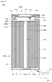
- FIG. 4 is a cross-sectional view illustrating a secondary battery according to another embodiment of the present disclosure.
- the secondary battery 200 includes a cylindrical case 210, an electrode assembly 120, and a cap assembly 230.
- the cylindrical case 210 may include a substantially circular bottom portion 111, a side wall 112 extending a certain length upward from the bottom portion 111, and a notch 215 provided on the bottom portion 111.
- the notch 215 may be formed to a certain depth on the lower surface of the bottom portion 111. In some examples, the notch 215 may be provided on the upper surface of the bottom portion 111 or may be provided on both the upper and lower surfaces. The notch 215 may be located outside a portion of the bottom portion 111 where the negative electrode tab 124 is welded. The notch 215 may be continuously formed on the bottom portion 111. In some examples, the notch 215 may include a plurality of notches formed in the bottom portion 111 at a certain interval.
- the notch 215 when the internal pressure of the secondary battery is higher than a reference pressure, the notch 215 may be broken to discharge the internal gas of the cylindrical case 110 to the outside (lower side), and thus the safety of the secondary battery can be ensured.
- the negative electrode tab 124 and the sidewall 112 of the cylindrical case 110 may be electrically separated, thereby blocking the current flowing to the terminal plate 135.
- the cap assembly 230 may include a cap-up 131 provided with a plurality of through-holes 131a, a cap-down 133 installed under the cap-up 131, a terminal plate 135 installed above the cap-up 131, a first insulating gasket 136 interposed between the terminal plate 135 and the cap-up 131, and a second insulating gasket 137 interposed between the cap-down 133 and the cylindrical case 210.
- the cap assembly 230 shown in FIG. 4 may have a structure in which the vent plate 132 and the insulator 134 are omitted from the cap assembly 130 shown in FIG. 2 .
- the notch 215 provided in the cylindrical case 210 may serve as the vent plate 132 and the insulator 134.
- the secondary battery according to an embodiment of the present disclosure includes a terminal plate electrically connected to a cylindrical case and installed in the same direction as a cap-up, thereby facilitating welding with an external device.
Landscapes
- Chemical & Material Sciences (AREA)
- Chemical Kinetics & Catalysis (AREA)
- Electrochemistry (AREA)
- General Chemical & Material Sciences (AREA)
- Engineering & Computer Science (AREA)
- Manufacturing & Machinery (AREA)
- Inorganic Chemistry (AREA)
- Sealing Battery Cases Or Jackets (AREA)
- Secondary Cells (AREA)
Abstract
The present disclosure relates to a secondary battery capable of facilitating welding with an external device. As an example, disclosed is a secondary battery comprising: a cylindrical case; an electrode assembly accommodated in the cylindrical case; and a cap assembly sealing the cylindrical case and including a cap-up electrically connected to a positive electrode of the electrode assembly, a terminal plate coupled to an upper portion of the cap-up and electrically connected to a negative electrode of the electrode assembly, and a first insulating gasket interposed between the cap-up and the terminal plate.
Description
- The present disclosure relates to a secondary battery.
- Lithium ion secondary batteries are used as power sources for hybrid vehicles or electric vehicles as well as portable electronic devices because of, for example, a high operating voltage and a high energy density per unit weight.
- Secondary batteries may be classified as cylindrical, prismatic, or pouch-shaped secondary batteries according to shape. For example, a cylindrical secondary battery generally includes a cylindrical case, a cylindrical electrode assembly that is coupled to the case, an electrolyte (optional) that is injected into the case to enable movement of lithium ions, and a cap assembly that is coupled to one side of the case to prevent leakage of the electrolyte and prevents separation of the electrode assembly.
- The above information disclosed in this Background section is only for enhancement of understanding of the background of the invention and therefore it may contain information that does not constitute prior art.
- The present disclosure provides a secondary battery capable of facilitating welding with an external device.
- A secondary battery according to the present disclosure includes: a cylindrical case; an electrode assembly accommodated in the cylindrical case; and a cap assembly sealing the cylindrical case and including a cap-up electrically connected to a positive electrode of the electrode assembly, a terminal plate coupled to an upper portion of the cap-up and electrically connected to a negative electrode of the electrode assembly, and a first insulating gasket interposed between the cap-up and the terminal plate.
- The terminal plate may be electrically connected to the cylindrical case.
- The cylindrical case may include a beading part recessed inwardly at the lower part of the cap assembly and a crimping part bent inwardly at the upper part of the cap assembly, and the crimping part covers a portion of the terminal plate.
- The terminal plate may be located above the edge of the cap-up and may expose a central portion protruding upward from the cap-up.
- The area of the terminal plate may correspond to the area of the edge of the cap-up.
- The first insulating gasket may be located between the edge of the cap-up and the terminal plate, and the area of the first insulating gasket may be larger than that of the terminal plate.
- The first insulating gasket may include an extension part extending upward and covering a side surface of the terminal plate.
- The secondary battery may further include a second insulating gasket interposed between the cap-up and the cylindrical case.
- The secondary battery may further include: a vent plate installed under the cap-up and provided with a notch; a cap-down installed under the vent plate and provided with a plurality of through holes; and an insulator interposed between the vent plate and the cap-down.
- The cylindrical case may include a notch provided on a bottom surface.
- At least some of the above and other features of the invention are set out in the claims.
-
-
FIG. 1 is a perspective view illustrating a secondary battery according to an embodiment of the present disclosure. -
FIG. 2 is a cross-sectional view illustrating a secondary battery according to an embodiment of the present disclosure. -
FIGS. 3A and 3B are enlarged cross-sectional views of portion A ofFIG. 2 . -
FIG. 4 is a cross-sectional view illustrating a secondary battery according to another embodiment of the present disclosure. - Hereinafter, preferred embodiments of the present invention will be described in detail with reference to the accompanying drawings.
- Examples of the present invention are provided to more completely explain the present invention to those skilled in the art, and the following examples may be modified in various other forms. The present invention, however, may be embodied in many different forms and should not be construed as being limited to the example embodiments set forth herein. Rather, these example embodiments are provided so that this disclosure will be thorough and complete and will convey the aspects and features of the present invention to those skilled in the art.
- In addition, in the accompanying drawings, sizes or thicknesses of various components are exaggerated for brevity and clarity. Like numbers refer to like elements throughout. As used herein, the term "and/or" includes any and all combinations of one or more of the associated listed items. In addition, it will be understood that when an element A is referred to as being "connected to" an element B, the element A can be directly connected to the element B or an intervening element C may be present therebetween such that the element A and the element B are indirectly connected to each other.
- The terminology used herein is for the purpose of describing particular embodiments only and is not intended to be limiting of the disclosure. As used herein, the singular forms are intended to include the plural forms as well, unless the context clearly indicates otherwise. It will be further understood that the terms "comprise or include" and/or "comprising or including," when used in this specification, specify the presence of stated features, numbers, steps, operations, elements, and/or components, but do not preclude the presence or addition of one or more other features, numbers, steps, operations, elements, components, and/or groups thereof.
- It will be understood that, although the terms first, second, etc. may be used herein to describe various members, elements, regions, layers and/or sections, these members, elements, regions, layers and/or sections should not be limited by these terms. These terms are only used to distinguish one member, element, region, layer and/or section from another. Thus, for example, a first member, a first element, a first region, a first layer and/or a first section discussed below could be termed a second member, a second element, a second region, a second layer and/or a second section without departing from the teachings of the present invention.
- Spatially relative terms, such as "beneath," "below," "lower," "above," "upper," and the like, may be used herein for ease of description to describe one element or feature's relationship to another element(s) or feature(s) as illustrated in the figures. It will be understood that the spatially relative terms are intended to encompass different orientations of the device in use or operation in addition to the orientation depicted in the figures. For example, if the element or feature in the figures is turned over, elements described as "below" or "beneath" other elements or features would then be oriented "on" or "above" the other elements or features. Thus, the term "below" can encompass both an orientation of above and below.
-
FIG. 1 is a perspective view illustrating a secondary battery according to an embodiment of the present disclosure.FIG. 2 is a cross-sectional view illustrating a secondary battery according to an embodiment of the present disclosure.FIGS. 3A and 3B are enlarged cross-sectional views of portion A ofFIG. 2 . - Referring to
FIGS. 1 to 3B , thesecondary battery 100 according to an embodiment of the present disclosure includes acylindrical case 110, anelectrode assembly 120, and acap assembly 130. In some examples, thecap assembly 130 may include or be referred to as a cap, a cap group, a cap assembly, a cover, or a lid. - The
cylindrical case 110 may include a substantiallycircular bottom portion 111 and asidewall 112 extending a predetermined length upward from thebottom portion 111. In some examples, thecylindrical case 110 may include or be referred to as a can, an exterior material, or a housing. - During the manufacturing process of the secondary battery, the top of the
cylindrical case 110 may be opened. Therefore, during the assembly process of the secondary battery, theelectrode assembly 120 may be integrated into one structure and inserted into thecylindrical case 110. Of course, an electrolyte may be additionally injected into thecylindrical case 110 in a subsequent process. - The
cylindrical case 110 may be made of steel, a steel alloy, nickel-plated steel, a nickel-plated steel alloy, aluminium, or an aluminium alloy. - In addition, the
cylindrical case 110 may be provided with abeading part 113 recessed inwardly at the lower part of thecap assembly 130 so as to prevent thecap assembly 130 from escaping to the outside, and a crimpingpart 114 bent inwardly at the upper part of thecap assembly 130. - The
electrode assembly 120 may be accommodated inside thecylindrical case 110. Theelectrode assembly 120 may include or be referred to as an electrode, an electrode group, or a jelly roll. Theelectrode assembly 120 may include anegative electrode plate 121 coated with a negative electrode active material (e.g., graphite, carbon, etc.), apositive electrode plate 122 coated with a positive electrode active material (e.g., transition metal oxide (LiCoO2, LiNiO2, LiMn2O4, etc.)), and aseparator 123 located between thenegative electrode plate 121 and thepositive electrode plate 122 to prevent a short circuit and to allow only the movement of lithium ions. Thenegative electrode plate 121, thepositive electrode plate 122, and theseparator 123 may be wound in a substantially cylindrical shape. In some examples, thenegative electrode plate 121 may be a copper (Cu) foil, thepositive electrode plate 122 may be an aluminium (Al) foil, and theseparator 123 may be polyethylene (PE) or polypropylene (PP). - In addition, a
negative electrode tab 124 that protrudes and extends a certain length downward may be welded to thenegative electrode plate 121, and apositive electrode tab 125 that protrudes and extends a certain length upward is welded to thepositive electrode plate 122. In addition, thenegative electrode tab 124 may be copper (Cu) or nickel (Ni), and thepositive electrode tab 125 may be aluminium (Al). - In addition, the
negative electrode tab 124 of theelectrode assembly 120 may be welded to thebottom portion 111 of thecylindrical case 110. Therefore, thecylindrical case 110 can operate as a negative electrode. In some examples, thenegative electrode tab 124 may be ultrasonically or laser welded to thebottom portion 111 of thecylindrical case 110. Of course, on the contrary, thepositive electrode tab 125 may be welded to thebottom portion 111 of thecylindrical case 110, and in this case, thecylindrical case 110 may operate as a positive electrode. - In addition, a
first insulation plate 126 coupled to thecylindrical case 110 and having afirst hole 126a at the center and asecond hole 126b outside thereof may be interposed between theelectrode assembly 120 and thebottom portion 111. In some examples, thefirst insulation plate 126 prevents theelectrode assembly 120 from electrically contacting thebottom portion 111 of thecylindrical case 110. In some examples, thefirst hole 126a allows gas to quickly move upward through acenter pin 140 when a large amount of gas is generated due to an abnormality of the secondary battery, and thesecond hole 126b allows thenegative electrode tab 124 to pass through and be welded to thebottom portion 111. - In addition, a
second insulation plate 127 coupled to thecylindrical case 110 and having afirst hole 127a at the center and a plurality ofsecond holes 127b outside thereof may be interposed between theelectrode assembly 120 and thecap assembly 130. In some examples, thesecond insulation plate 127 prevents theelectrode assembly 120 from electrically contacting thecap assembly 130. In some examples, thesecond insulation plate 127 prevents thenegative electrode plate 121 of theelectrode assembly 120 from electrically contacting thecap assembly 130. In some examples, thefirst hole 127a allows the gas to quickly move to thecap assembly 130 when a large amount of gas is generated due to an abnormality of the secondary battery, and one of thesecond holes 127b allows thepositive electrode tab 125 to pass therethrough and be welded to thecap assembly 130. In addition, the remainingsecond holes 127b serve to allow an electrolyte to quickly flow into theelectrode assembly 120 in an electrolyte injection process. - In addition, the diameters of the
first holes plates center pin 140, and thus prevents thecenter pin 140 from electrically contacting thebottom portion 111 of thecylindrical case 110 or thecap assembly 130 due to an external impact. - The
center pin 140 has a shape of a hollow circular pipe and may be coupled to approximately the center of theelectrode assembly 120. Thecenter pin 140 may be made of steel, stainless steel, aluminium, aluminium alloy, or polybutylene terephthalate, but the material is not limited thereto. Thecenter pin 140 serves to suppress deformation of theelectrode assembly 120 during charging and discharging of the secondary battery and serves as a passage for gas generated inside the secondary battery. In some cases, thecenter pin 140 may be omitted. - The
cap assembly 130 may seal an opening of thecylindrical case 110 to protect theelectrode assembly 120 from external environments, and, when the internal pressure of thecylindrical case 110 is higher than a reference pressure, may be broken to discharge the internal gas of thecylindrical case 110 to the outside. In some examples, thecap assembly 130 may also serve as a positive electrode terminal. - The
cap assembly 130 may include a cap-up 131 provided with a plurality of through-holes 131a, avent plate 132 installed under the cap-up 131, a cap-down 133 installed under thevent plate 132 and provided with a plurality of through-holes 133a, aninsulator 134 interposed between thevent plate 132 and the cap-down 133, aterminal plate 135 installed above the cap-up 131, a first insulatinggasket 136 interposed between theterminal plate 135 and the cap-up 131, and a second insulatinggasket 137 interposed between the cap-down 133 and thecylindrical case 110. - The cap-
up 131 may protruding upward at the center thereof to serve as a terminal electrically connected to an external device. In some examples, the cap-up 131 may serve as a positive electrode terminal. The plurality of through-holes 131a provided in the cap-up 131 may serve to discharge internal gas to the outside when an abnormal internal pressure occurs inside thecylindrical case 110 due to overcharging, etc. In some examples, the cap-up 131 may include or be referred to as a cap, a conductor plate, a cover, or a lid. In some examples, the cap-up 131 may be made of aluminium or an aluminium alloy. - The
vent plate 132 may be located under the cap-up 131. In some examples, thevent plate 132 may be closely attached to, in contact with, bonded to, or connected to the lower portion of the cap-up 131. Specifically, thevent plate 132 may be closely attached to, in contact with, bonded to, or connected to the edge of the cap-up 131, except for the upwardly protruding center of the cap-up 131. In some examples, thevent plate 132 may include or be referred to as a safety vent, a safety plate, a vent, a valve, a thin plate, or a conductor plate. In some examples, thevent plate 132 may be made of aluminium or an aluminium alloy. - The
vent plate 132 may further include anotch 132a formed at a predetermined depth on the upper surface. In some examples, thenotch 132a may be provided at a position corresponding to the throughhole 133a of the cap-down 133. In some examples, when the internal pressure of the secondary battery is greater than a reference pressure (or the breaking pressure of the vent plate), thenotch 132a may be broken due to internal gas, so that the internal gas of thecylindrical case 110 is released to the outside through the through-holes 131a of the cap-up 131, and thus the safety of the secondary battery can be secured. - The cap-down 133 may be closely attached to, in contact with, bonded to, or connected to the lower portion of the
vent plate 132. The cap-down 133 may be electrically connected to theelectrode assembly 120 through thepositive electrode tab 125. Thepositive electrode tab 125 of theelectrode assembly 120 may be welded to the lower surface of the cap-down 133. In some examples, the lower surface of the cap-down 133 may be ultrasonically and/or laser welded to thepositive electrode tab 125. In some examples, the cap-down 133 may be made of aluminium or an aluminium alloy. - In some examples, when the internal pressure of the secondary battery is greater than the reference pressure (or the rupture pressure of the vent plate), the
vent plate 132 may be deformed by the internal gas, and thus the cap-down 133 and thevent plate 132 can be electrically separated. - The
insulator 134 may be located between the edge of thevent plate 132 and the edge of the cap-down 133. When thevent plate 132 is deformed by internal gas, theinsulator 134 may serve to insulate the cap-down 133 and thevent plate 132 from each other. In some examples, theinsulator 134 may be made of a resin material, such as polyethylene (PE), polypropylene (PP), polyethylene terephthalate (PET), etc., but the material is not limited thereto. - The
terminal plate 135 may be positioned above the edge of the cap-up 131. Theterminal plate 135 may have a hole formed at the center, so that the center protruding upward from the cap-up 131 may be exposed to the outside. In some examples, theterminal plate 135 may be formed in a ring shape. Theterminal plate 135 may be spaced apart from the center of the cap-up 131. In addition, theterminal plate 135 may be insulated from the cap-up 131 by the first insulatinggasket 136. - In some examples, the area of the
terminal plate 135 may correspond to the area of the edge of the cap-up 131. In addition, theterminal plate 135 that serves as the negative electrode terminal may be exposed in the same direction as the center of the cap-up 131 that serves as the positive electrode terminal. Accordingly, thesecondary battery 100 according to the present disclosure may be easily coupled or welded to the positive electrode and the negative electrode of an external device (or a battery pack). - Referring to
FIG. 3A , the first insulatinggasket 136 is interposed between the cap-up 131 and theterminal plate 135 to insulate the cap-up 131 and theterminal plate 135 from each other. The first insulatinggasket 136 may have a ring shape in which a hole is formed in the center. In some examples, the first insulatinggasket 136 may be formed to have a larger area than theterminal plate 135 and the edge of the cap-up 131. - The lower surface of the first insulating
gasket 136 may be in contact with or closely attached to the edge of the cap-up 131 and the second insulatinggasket 137, and the upper surface of the first insulatinggasket 136 may be in contact with or closely attached to theterminal plate 135. The outer surface of the first insulatinggasket 136 may be in contact with or closely attached to thecylindrical case 110. - In some examples, the first insulating
gasket 136 may include or be referred to as a sealing gasket, an insulator, or a resin. The first insulatinggasket 136 may be made of a resin material, such as polyethylene (PE), polypropylene (PP), polyethylene terephthalate (PET), etc., but the material is not limited thereto. - Referring to
FIG. 3B , the first insulatinggasket 136 may further include anextension part 136a extending upward and covering the side surface of theterminal plate 135. Theextension part 136a may be located on both edges of the first insulatinggasket 136 to cover inner and outer surfaces of theterminal plate 135. In this way, the first insulatinggasket 136 may prevent theterminal plate 135 from contacting the cap-up 131. - The second
insulating gasket 137 may be interposed between thecylindrical case 110, and the cap-up 131, thevent plate 132 and the cap-down 133. The secondinsulating gasket 137 may cover the outer circumferences of the cap-up 131, thevent plate 132, and the cap-down 133. The outer surface of the second insulatinggasket 137 may be in contact with or closely attached to thecylindrical case 110. The secondinsulating gasket 137 may be made of a resin material, such as polyethylene (PE), polypropylene (PP), polyethylene terephthalate (PET), etc., but the material is not limited thereto. - The second
insulating gasket 137 may be in close contact with thebeading part 113, and the inner surface of the second insulatinggasket 137 may be in close contact with the edges of the cap-up 131, thevent plate 132, and the cap-down 133. In some examples, the second insulatinggasket 137 may include or be referred to as a sealing gasket, an insulator, or a resin. The secondinsulating gasket 137 may be made of a resin material, such as polyethylene (PE), polypropylene (PP), polyethylene terephthalate (PET), etc., but the material is not limited thereto. -
FIG. 4 is a cross-sectional view illustrating a secondary battery according to another embodiment of the present disclosure. - Referring to
FIG. 4 , thesecondary battery 200 according to another embodiment of the present disclosure includes acylindrical case 210, anelectrode assembly 120, and acap assembly 230. - The
cylindrical case 210 may include a substantiallycircular bottom portion 111, aside wall 112 extending a certain length upward from thebottom portion 111, and anotch 215 provided on thebottom portion 111. - The
notch 215 may be formed to a certain depth on the lower surface of thebottom portion 111. In some examples, thenotch 215 may be provided on the upper surface of thebottom portion 111 or may be provided on both the upper and lower surfaces. Thenotch 215 may be located outside a portion of thebottom portion 111 where thenegative electrode tab 124 is welded. Thenotch 215 may be continuously formed on thebottom portion 111. In some examples, thenotch 215 may include a plurality of notches formed in thebottom portion 111 at a certain interval. - In some examples, when the internal pressure of the secondary battery is higher than a reference pressure, the
notch 215 may be broken to discharge the internal gas of thecylindrical case 110 to the outside (lower side), and thus the safety of the secondary battery can be ensured. In addition, when thenotch 215 is broken, thenegative electrode tab 124 and thesidewall 112 of thecylindrical case 110 may be electrically separated, thereby blocking the current flowing to theterminal plate 135. - The
cap assembly 230 may include a cap-up 131 provided with a plurality of through-holes 131a, a cap-down 133 installed under the cap-up 131, aterminal plate 135 installed above the cap-up 131, a first insulatinggasket 136 interposed between theterminal plate 135 and the cap-up 131, and a second insulatinggasket 137 interposed between the cap-down 133 and thecylindrical case 210. - The
cap assembly 230 shown inFIG. 4 may have a structure in which thevent plate 132 and theinsulator 134 are omitted from thecap assembly 130 shown inFIG. 2 . In thesecondary battery 200 according to the present disclosure, instead of thevent plate 132 and theinsulator 134 being omitted, thenotch 215 provided in thecylindrical case 210 may serve as thevent plate 132 and theinsulator 134. - As described above, the secondary battery according to an embodiment of the present disclosure includes a terminal plate electrically connected to a cylindrical case and installed in the same direction as a cap-up, thereby facilitating welding with an external device.
- While the foregoing embodiment is only one embodiment for carrying out the secondary battery according to the present disclosure, which is not limited to the embodiment, it will be understood by a person skilled in the art that various changes in form and details may be made therein without departing from the scope of the present disclosure as defined by the following claims.
Claims (10)
- A secondary battery comprising:a cylindrical case;an electrode assembly accommodated in the cylindrical case; anda cap assembly sealing the cylindrical case and including a cap-up electrically connected to a positive electrode of the electrode assembly, a terminal plate coupled to an upper portion of the cap-up and electrically connected to a negative electrode of the electrode assembly, and a first insulating gasket interposed between the cap-up and the terminal plate.
- The secondary battery of claim 1, wherein the terminal plate is electrically connected to the cylindrical case.
- The secondary battery of claim 1 or claim 2, wherein the cylindrical case includes a beading part recessed inwardly at the lower part of the cap assembly and a crimping part bent inwardly at the upper part of the cap assembly, and the crimping part covers a portion of the terminal plate.
- The secondary battery of any one of claims 1 to 3, wherein the terminal plate is located above the edge of the cap-up and exposes a central portion protruding upward from the cap-up.
- The secondary battery of any one of claims 1 to 4, wherein the area of the terminal plate corresponds to the area of the edge of the cap-up.
- The secondary battery of any one of claims 1 to 5, wherein the first insulating gasket is located between the edge of the cap-up and the terminal plate, and the area of the first insulating gasket is larger than that of the terminal plate.
- The secondary battery of any one of claims 1 to 6, wherein the first insulating gasket includes an extension part extending upward and covering a side surface of the terminal plate.
- The secondary battery of any one of claims 1 to 7, further comprising a second insulating gasket interposed between the cap-up and the cylindrical case.
- The secondary battery of any one of claims 1 to 8, further comprising:a vent plate installed under the cap-up and provided with a notch;a cap-down installed under the vent plate and provided with a plurality of through holes; andan insulator interposed between the vent plate and the cap-down.
- The secondary battery of any one of claims 1 to 9, wherein the cylindrical case includes a notch provided on a bottom surface.
Applications Claiming Priority (1)
| Application Number | Priority Date | Filing Date | Title |
|---|---|---|---|
| KR1020220012600A KR102619683B1 (en) | 2022-01-27 | 2022-01-27 | Secondary Battery |
Publications (1)
| Publication Number | Publication Date |
|---|---|
| EP4254579A1 true EP4254579A1 (en) | 2023-10-04 |
Family
ID=85132728
Family Applications (1)
| Application Number | Title | Priority Date | Filing Date |
|---|---|---|---|
| EP23153647.5A Pending EP4254579A1 (en) | 2022-01-27 | 2023-01-27 | Secondary battery |
Country Status (4)
| Country | Link |
|---|---|
| US (1) | US20230238616A1 (en) |
| EP (1) | EP4254579A1 (en) |
| KR (2) | KR102619683B1 (en) |
| CN (1) | CN116505154A (en) |
Families Citing this family (5)
| Publication number | Priority date | Publication date | Assignee | Title |
|---|---|---|---|---|
| EP4697465A1 (en) * | 2023-11-01 | 2026-02-18 | LG Energy Solution, Ltd. | Battery, and battery pack and vehicle including same |
| WO2025110866A1 (en) * | 2023-11-24 | 2025-05-30 | 주식회사 엘지에너지솔루션 | Cap gasket of cylindrical secondary battery, and cylindrical secondary battery using same |
| KR20250108988A (en) * | 2024-01-09 | 2025-07-16 | 삼성에스디아이 주식회사 | Battery cell and manufacturing method thereof |
| KR20250115545A (en) * | 2024-01-24 | 2025-07-31 | 삼성에스디아이 주식회사 | Secondary battery |
| KR20250179461A (en) * | 2024-06-21 | 2025-12-30 | 삼성에스디아이 주식회사 | Secondary battery |
Citations (4)
| Publication number | Priority date | Publication date | Assignee | Title |
|---|---|---|---|---|
| EP2626925A2 (en) * | 2010-12-07 | 2013-08-14 | LG Chem, Ltd. | Cap assembly and second battery using same |
| EP2696387A1 (en) * | 2012-08-08 | 2014-02-12 | Samsung SDI Co., Ltd. | Lithium ion secondary battery |
| US20170301899A1 (en) * | 2016-04-14 | 2017-10-19 | Samsung Sdi Co., Ltd. | Secondary battery |
| EP3547392A1 (en) * | 2016-11-22 | 2019-10-02 | Samsung SDI Co., Ltd. | Secondary battery |
Family Cites Families (3)
| Publication number | Priority date | Publication date | Assignee | Title |
|---|---|---|---|---|
| KR101242135B1 (en) * | 2007-12-13 | 2013-03-12 | 삼성에스디아이 주식회사 | Cylinder type secondary battery |
| KR102209831B1 (en) * | 2014-02-20 | 2021-01-29 | 삼성에스디아이 주식회사 | Cap assembly and secondary battery comprising the same |
| KR101932812B1 (en) * | 2015-06-04 | 2018-12-27 | 신흥에스이씨주식회사 | Method of manufacturing CID assembly for a secondary battery and the CID assembly thereof |
-
2022
- 2022-01-27 KR KR1020220012600A patent/KR102619683B1/en active Active
-
2023
- 2023-01-27 EP EP23153647.5A patent/EP4254579A1/en active Pending
- 2023-01-27 US US18/160,903 patent/US20230238616A1/en active Pending
- 2023-01-28 CN CN202310087632.5A patent/CN116505154A/en active Pending
- 2023-12-26 KR KR1020230191565A patent/KR20240004184A/en active Pending
Patent Citations (4)
| Publication number | Priority date | Publication date | Assignee | Title |
|---|---|---|---|---|
| EP2626925A2 (en) * | 2010-12-07 | 2013-08-14 | LG Chem, Ltd. | Cap assembly and second battery using same |
| EP2696387A1 (en) * | 2012-08-08 | 2014-02-12 | Samsung SDI Co., Ltd. | Lithium ion secondary battery |
| US20170301899A1 (en) * | 2016-04-14 | 2017-10-19 | Samsung Sdi Co., Ltd. | Secondary battery |
| EP3547392A1 (en) * | 2016-11-22 | 2019-10-02 | Samsung SDI Co., Ltd. | Secondary battery |
Also Published As
| Publication number | Publication date |
|---|---|
| KR102619683B1 (en) | 2023-12-29 |
| CN116505154A (en) | 2023-07-28 |
| US20230238616A1 (en) | 2023-07-27 |
| KR20230115758A (en) | 2023-08-03 |
| KR20240004184A (en) | 2024-01-11 |
Similar Documents
| Publication | Publication Date | Title |
|---|---|---|
| EP4254579A1 (en) | Secondary battery | |
| US20230231242A1 (en) | Secondary battery | |
| EP4199199B1 (en) | Secondary battery | |
| US8753765B2 (en) | Secondary battery | |
| US11289782B2 (en) | Secondary battery | |
| CN114175380B (en) | Secondary battery | |
| EP3518305B1 (en) | Secondary battery | |
| EP4117096A1 (en) | Secondary battery | |
| US11664523B2 (en) | Secondary battery | |
| EP4210139A2 (en) | Secondary battery | |
| KR102323809B1 (en) | The Apparatus For Venting And The Method For Manufacturing Thereof | |
| US20230223643A1 (en) | Secondary battery | |
| US12476310B2 (en) | Secondary battery and manufacturing method of secondary battery | |
| KR102661207B1 (en) | Secondary Battery | |
| US11527800B2 (en) | Secondary battery | |
| US20240145853A1 (en) | Secondary battery | |
| EP4290673A1 (en) | Secondary battery |
Legal Events
| Date | Code | Title | Description |
|---|---|---|---|
| PUAI | Public reference made under article 153(3) epc to a published international application that has entered the european phase |
Free format text: ORIGINAL CODE: 0009012 |
|
| STAA | Information on the status of an ep patent application or granted ep patent |
Free format text: STATUS: REQUEST FOR EXAMINATION WAS MADE |
|
| 17P | Request for examination filed |
Effective date: 20230127 |
|
| AK | Designated contracting states |
Kind code of ref document: A1 Designated state(s): AL AT BE BG CH CY CZ DE DK EE ES FI FR GB GR HR HU IE IS IT LI LT LU LV MC ME MK MT NL NO PL PT RO RS SE SI SK SM TR |