EP4254570A1 - Humidifier for fuel cell - Google Patents
Humidifier for fuel cell Download PDFInfo
- Publication number
- EP4254570A1 EP4254570A1 EP21898119.9A EP21898119A EP4254570A1 EP 4254570 A1 EP4254570 A1 EP 4254570A1 EP 21898119 A EP21898119 A EP 21898119A EP 4254570 A1 EP4254570 A1 EP 4254570A1
- Authority
- EP
- European Patent Office
- Prior art keywords
- humidifying membrane
- separator
- humidifying
- outer edge
- water
- Prior art date
- Legal status (The legal status is an assumption and is not a legal conclusion. Google has not performed a legal analysis and makes no representation as to the accuracy of the status listed.)
- Pending
Links
Images




Classifications
-
- B—PERFORMING OPERATIONS; TRANSPORTING
- B01—PHYSICAL OR CHEMICAL PROCESSES OR APPARATUS IN GENERAL
- B01D—SEPARATION
- B01D63/00—Apparatus in general for separation processes using semi-permeable membranes
- B01D63/08—Flat membrane modules
- B01D63/082—Flat membrane modules comprising a stack of flat membranes
- B01D63/0822—Plate-and-frame devices
-
- H—ELECTRICITY
- H01—ELECTRIC ELEMENTS
- H01M—PROCESSES OR MEANS, e.g. BATTERIES, FOR THE DIRECT CONVERSION OF CHEMICAL ENERGY INTO ELECTRICAL ENERGY
- H01M8/00—Fuel cells; Manufacture thereof
- H01M8/04—Auxiliary arrangements, e.g. for control of pressure or for circulation of fluids
- H01M8/04082—Arrangements for control of reactant parameters, e.g. pressure or concentration
- H01M8/04089—Arrangements for control of reactant parameters, e.g. pressure or concentration of gaseous reactants
- H01M8/04119—Arrangements for control of reactant parameters, e.g. pressure or concentration of gaseous reactants with simultaneous supply or evacuation of electrolyte; Humidifying or dehumidifying
- H01M8/04126—Humidifying
- H01M8/04149—Humidifying by diffusion, e.g. making use of membranes
-
- B—PERFORMING OPERATIONS; TRANSPORTING
- B01—PHYSICAL OR CHEMICAL PROCESSES OR APPARATUS IN GENERAL
- B01D—SEPARATION
- B01D63/00—Apparatus in general for separation processes using semi-permeable membranes
- B01D63/08—Flat membrane modules
- B01D63/082—Flat membrane modules comprising a stack of flat membranes
- B01D63/084—Flat membrane modules comprising a stack of flat membranes at least one flow duct intersecting the membranes
- B01D63/085—Flat membrane modules comprising a stack of flat membranes at least one flow duct intersecting the membranes specially adapted for two fluids in mass exchange flow
-
- B—PERFORMING OPERATIONS; TRANSPORTING
- B01—PHYSICAL OR CHEMICAL PROCESSES OR APPARATUS IN GENERAL
- B01D—SEPARATION
- B01D69/00—Semi-permeable membranes for separation processes or apparatus characterised by their form, structure or properties; Manufacturing processes specially adapted therefor
- B01D69/10—Supported membranes; Membrane supports
-
- H—ELECTRICITY
- H01—ELECTRIC ELEMENTS
- H01M—PROCESSES OR MEANS, e.g. BATTERIES, FOR THE DIRECT CONVERSION OF CHEMICAL ENERGY INTO ELECTRICAL ENERGY
- H01M8/00—Fuel cells; Manufacture thereof
- H01M8/02—Details
- H01M8/0202—Collectors; Separators, e.g. bipolar separators; Interconnectors
- H01M8/0258—Collectors; Separators, e.g. bipolar separators; Interconnectors characterised by the configuration of channels, e.g. by the flow field of the reactant or coolant
-
- H—ELECTRICITY
- H01—ELECTRIC ELEMENTS
- H01M—PROCESSES OR MEANS, e.g. BATTERIES, FOR THE DIRECT CONVERSION OF CHEMICAL ENERGY INTO ELECTRICAL ENERGY
- H01M8/00—Fuel cells; Manufacture thereof
- H01M8/04—Auxiliary arrangements, e.g. for control of pressure or for circulation of fluids
-
- H—ELECTRICITY
- H01—ELECTRIC ELEMENTS
- H01M—PROCESSES OR MEANS, e.g. BATTERIES, FOR THE DIRECT CONVERSION OF CHEMICAL ENERGY INTO ELECTRICAL ENERGY
- H01M8/00—Fuel cells; Manufacture thereof
- H01M8/04—Auxiliary arrangements, e.g. for control of pressure or for circulation of fluids
- H01M8/04082—Arrangements for control of reactant parameters, e.g. pressure or concentration
- H01M8/04089—Arrangements for control of reactant parameters, e.g. pressure or concentration of gaseous reactants
- H01M8/04119—Arrangements for control of reactant parameters, e.g. pressure or concentration of gaseous reactants with simultaneous supply or evacuation of electrolyte; Humidifying or dehumidifying
-
- H—ELECTRICITY
- H01—ELECTRIC ELEMENTS
- H01M—PROCESSES OR MEANS, e.g. BATTERIES, FOR THE DIRECT CONVERSION OF CHEMICAL ENERGY INTO ELECTRICAL ENERGY
- H01M8/00—Fuel cells; Manufacture thereof
- H01M8/04—Auxiliary arrangements, e.g. for control of pressure or for circulation of fluids
- H01M8/04082—Arrangements for control of reactant parameters, e.g. pressure or concentration
- H01M8/04089—Arrangements for control of reactant parameters, e.g. pressure or concentration of gaseous reactants
- H01M8/04119—Arrangements for control of reactant parameters, e.g. pressure or concentration of gaseous reactants with simultaneous supply or evacuation of electrolyte; Humidifying or dehumidifying
- H01M8/04126—Humidifying
- H01M8/04141—Humidifying by water containing exhaust gases
-
- H—ELECTRICITY
- H01—ELECTRIC ELEMENTS
- H01M—PROCESSES OR MEANS, e.g. BATTERIES, FOR THE DIRECT CONVERSION OF CHEMICAL ENERGY INTO ELECTRICAL ENERGY
- H01M8/00—Fuel cells; Manufacture thereof
- H01M8/04—Auxiliary arrangements, e.g. for control of pressure or for circulation of fluids
- H01M8/04291—Arrangements for managing water in solid electrolyte fuel cell systems
-
- B—PERFORMING OPERATIONS; TRANSPORTING
- B01—PHYSICAL OR CHEMICAL PROCESSES OR APPARATUS IN GENERAL
- B01D—SEPARATION
- B01D2313/00—Details relating to membrane modules or apparatus
- B01D2313/04—Specific sealing means
- B01D2313/041—Gaskets or O-rings
-
- Y—GENERAL TAGGING OF NEW TECHNOLOGICAL DEVELOPMENTS; GENERAL TAGGING OF CROSS-SECTIONAL TECHNOLOGIES SPANNING OVER SEVERAL SECTIONS OF THE IPC; TECHNICAL SUBJECTS COVERED BY FORMER USPC CROSS-REFERENCE ART COLLECTIONS [XRACs] AND DIGESTS
- Y02—TECHNOLOGIES OR APPLICATIONS FOR MITIGATION OR ADAPTATION AGAINST CLIMATE CHANGE
- Y02E—REDUCTION OF GREENHOUSE GAS [GHG] EMISSIONS, RELATED TO ENERGY GENERATION, TRANSMISSION OR DISTRIBUTION
- Y02E60/00—Enabling technologies; Technologies with a potential or indirect contribution to GHG emissions mitigation
- Y02E60/30—Hydrogen technology
- Y02E60/50—Fuel cells
Definitions
- the present invention relates to humidifiers for fuel cells that include a humidifying unit for providing moisture contained in water-containing air to dry air to produce humidified air.
- the fuel cells have been used.
- the fuel cells are provided with a humidifier in order to humidify cathode gas to be supplied to the cathode.
- Some of such humidifiers include a humidifying unit in which separators for guiding gas and water-permeable membranes are alternately arranged.
- Such a humidifier is described in, for example, Patent Document 1 shown below.
- Patent Document 1 describes a humidifier for a fuel cell.
- This humidifier for a fuel cell includes: a humidifying membrane serving as a humidifying member; incoming humidification channels communicating with an air supply passage through which air directed to an air electrode of the fuel cell passes; and outgoing humidification channels communicating with an air off-gas passage through which off-gas after power generation discharged from the air electrode of the fuel cell passes.
- the incoming humidification channels and the outgoing humidification channels are provided on plate members corresponding to the separators described above, and are arranged so as to face each other with the humidifying membrane interposed therebetween.
- Patent Document 1 Japanese Unexamined Patent Application Publication No. 2003-187839 ( JP 2003-187839 A )
- a very thin humidifying membrane is used in the structure in which the incoming humidification channels and the outgoing humidification channels are arranged so as to face each other with the humidifying membrane interposed therebetween, such as the structure in the technique described in Patent Document 1.
- Such a thin humidifying membrane is prone to damage when handled in, for example, a manufacturing process. Therefore, there is room for improvement in increasing the strength of the humidifying membrane.
- a characteristic configuration of a humidifier for a fuel cell is a humidifier for a fuel cell including a humidifying unit that provides moisture contained in water-containing air to dry air to produce humidified air, wherein the humidifying unit includes: a first separator that is in a form of a plate and that includes a dry gas channel in a central region of one surface of the first separator; a second separator that is in a form of a plate and that includes a water-containing gas channel in a central region of a surface of the second separator that faces the dry gas channel; a humidifying membrane that is located between the dry gas channel and the water-containing gas channel, and that provides moisture contained in gas flowing through the water-containing gas channel to the dry air flowing through the dry gas channel to produce the humidified air; two protective films that are provided so as to be stacked on a front and back of the humidifying membrane, and that reinforce the humidifying membrane; and a sealing material that is provided along a first outer edge portion of the humidifying membrane with the humidifying membrane and the
- the protective films can protect the humidifying membrane and reinforce the mechanical strength of the humidifying membrane. The risk of damage during the manufacturing process can thus be reduced. Moreover, adhesion between the humidifying membrane and the sealing material in the close contact region can be increased, so that leakage between the dry gas channel and the water-containing gas channel via the protective film can be prevented.
- a reinforcing member be provided on an opposite side from the humidifying membrane so as to face at least one of the protective films, and that the reinforcing member together with the humidifying membrane and the protective films be sandwiched by the sealing material between the first separator and the second separator.
- the reinforcing member be provided in contact with the protective film located between the second separator and the humidifying membrane.
- the humidifying membrane and the protective films are even less likely to be bent, so that deformation thereof can be more effectively reduced.
- the humidifying membrane have the close contact region on at least one of surfaces of the humidifying membrane.
- the humidifying membrane have the close contact region on the surface that faces the first separator.
- the humidifying membrane and the protective film have a plurality of portions parallel to each other, and that the close contact region have a same width in all of the plurality of parallel portions.
- the distance between the outer edge portion of the protective film and the outer edge portion of the humidifying membrane can be made equal in all of the plurality of parallel portions. Therefore, even if the humidifying membrane expands or contracts due to change in external environment, the protective film can follow such expansion or contraction, so that separation of the protective film can be prevented. Moreover, since the sealing material is uniformly in close contact with the humidifying membrane and the protective film, the humidifying membrane and the protective film are less likely to wrinkle.
- At least corners of the outer edge portion of the humidifying membrane have a circular arc shape, and that the width of the close contact region in the corners be equal to the width of the close contact region in the plurality of parallel portions so that the close contact region has the same width in an entire periphery of the humidifying membrane.
- the distance between the outer edge portion of the protective film and the outer edge portion of the humidifying membrane can be made equal in the entire periphery. Therefore, even if the humidifying membrane expands or contracts due to change in external environment, the protective film can follow such expansion or contraction, so that separation of the protective film can be prevented. Since the sealing material is uniformly in close contact with the humidifying membrane and the protective film in the entire periphery, the humidifying membrane and the protective film are less likely to wrinkle.
- corners of the second outer edge portion of the protective film have a circular arc shape.
- the distance between the outer edge portion of the protective film and the outer edge portion of the humidifying membrane can be made equal in the entire periphery. Therefore, even if the humidifying membrane expands or contracts due to change in external environment, the protective film can follow such expansion or contraction, so that separation of the protective film can be prevented. Since the sealing material is uniformly in close contact with the humidifying membrane and the protective film in the entire periphery, the humidifying membrane and the protective film are less likely to wrinkle.
- a humidifier for a fuel cell (hereinafter referred to as "humidifier") according to the present invention is configured to protect and reinforce a humidifying membrane.
- a humidifier 1 of an embodiment will be described below.
- FIG. 1 is a perspective view of a humidifier 1 according to a first embodiment.
- FIG. 2 is a diagram showing flow paths communicating with the humidifier 1.
- FIG. 3 is a side sectional view of part of a humidifying unit 10.
- the humidifier 1 includes a first plate 2, a second plate 3, and the humidifying unit 10.
- the humidifying unit 10 is provided so as to be sandwiched between the first plate 2 and the second plate 3.
- the humidifying unit 10 provides moisture contained in water-containing air to dry air to produce humidified air.
- the humidifying unit 10 is composed of a stack of a first separator 11, a second separator 12, a humidifying membrane 13, and protective films 14.
- the humidifying unit 10 is provided in such a manner that the second separator 12, the protective film 14, the humidifying membrane 13, the protective film 14, and the first separator 11 are stacked in this order between the first plate 2 and the second plate 3, with the stack being pressed in the stacking direction.
- the humidifying unit 10 is composed of a stack of a plurality of the stacks shown in FIG. 3 .
- the humidifier 1 is provided with a dry gas supply port 21, a humidified gas discharge port 22, a water-containing gas supply port 31, and a water-containing gas discharge port 32.
- the humidifying unit 10 has a quadrilateral shape as viewed in plan.
- the dry gas supply port 21 and the humidified gas discharge port 22 are located so as to face each other along a diagonal line of the quadrilateral shape, and the water-containing gas supply port 31 and the water-containing gas discharge port 32 are located so as to face each other along a diagonal line of the quadrilateral square.
- air (example of "dry air”) compressed by a compressor 41 is supplied to the dry gas supply port 21 of the humidifier 1 via a valve 42.
- the dry air supplied to the dry gas supply port 21 is humidified while flowing through dry gas channels 11C that will be described later, and is discharged as humidified air from the humidified gas discharge port 22.
- the humidified air discharged from the humidified gas discharge port 22 is introduced into a cathode gas supply path 43B and supplied to a fuel cell 43.
- the fuel cell 43 is supplied with fuel gas containing hydrogen gas and air containing oxygen gas (corresponding to the above "dry air”) and generates electricity.
- the fuel cell 43 discharges water-containing gas (example of "water-containing air”) containing a large amount of water in the form of water vapor.
- This water-containing gas is supplied to the water-containing gas supply port 31 through a cathode off-gas discharge path 43A.
- the water-containing gas supplied to the water-containing gas supply port 31 humidifies the dry air flowing through the dry gas channels 11C as it flows through water-containing gas channels 12C that will be described later.
- the water-containing gas is then discharged from the water-containing gas discharge port 32.
- the first separator 11 has the dry gas channels 11C in a central region of its one surface.
- the first separator 11 is in the form of a plate. Of a front surface 11A and a back surface 11B out of the surfaces of the plate-like first separator 11, the one surface is the front surface 11A. Therefore, when the first separator 11 is divided into an outer peripheral portion and a central portion as viewed in plan, the central region of the one surface is the region of the central portion. Accordingly, the first separator 11 has the dry gas channels 11C in the central region of the front surface 11A as viewed in plan.
- a sealing material 15, which will be described later, is provided on the outer peripheral portion of the front surface 11A of the first separator 11, as viewed in plan.
- the region of the front surface 11A where the sealing material 15 is provided is defined as the outer peripheral portion, and the region of the front surface 11A where the dry gas channels 11C are formed is defined as the central portion, as viewed in plan.
- the humidifying unit 10 includes a plurality of the first separators 11, and as shown in FIG. 2 , their dry gas channels 11C are configured to communicate with the dry gas supply port 21 through a dry gas supply path 51 and a supply port 71. With this configuration, the dry air from the compressor 41 can be introduced into the dry gas channels 11C as described above.
- the first separator 11 may have the dry gas channels 11C or the water-containing gas channels 12C in the central region of the back surface 11B, in addition to the front surface 11A.
- the second separator 12 has the water-containing gas channels 12C in a central region of one surface thereof.
- the second separator 12 is in the form of a plate. Of a front surface 12A and a back surface 12B out of the surfaces of the plate-like second separator 12, the one surface is the front surface 12A. Therefore, when the second separator 12 is divided into an outer peripheral portion and a central portion as viewed in plan, the central region of the one surface is the region of the central portion. Accordingly, the second separator 12 has the water-containing gas channels 12C in the central region of the front surface 12A as viewed in plan.
- the sealing material 15, which will be described later, is also provided on the outer peripheral portion of the front surface 12A of the second separator 12, as viewed in plan.
- the region of the front surface 12A where the sealing material 15 is provided is defined as the outer peripheral portion, and the region of the front surface 12A where the water-containing gas channels 12C are formed is defined as the central portion, as viewed in plan.
- the humidifying unit 10 also includes a plurality of the second separators 12, and as shown in FIG. 2 , their water-containing gas channels 12C are configured to communicate with the water-containing gas supply port 31 through a water-containing gas supply path 61 and a supply port 81. With this configuration, the water-containing gas from the fuel cell 43 can be introduced.
- the second separator 12 may have the water-containing gas channels 12C or the dry gas channels 11C in the central region of the back surface 12B, in addition to the front surface 12A.
- the humidifying membrane 13 is located between the dry gas channels 11C and the water-containing gas channels 12C in the stacking direction.
- "Between the dry gas channels 11C and the water-containing gas channels 12C” means between the central region of the first separator 11 and the central region of the second separator 12 described above. Therefore, the humidifying membrane 13 is located between the central region of the first separator 11 and the central region of the second separator 12. That is, the dry gas channels 11C and the water-containing gas channels 12C face each other with the humidifying membrane 13 interposed therebetween.
- the humidifying unit 10 also includes a plurality of the humidifying membranes 13.
- Such a humidifying membrane 13 provides moisture contained in the gas flowing through the water-containing gas channels 12C to the dry air flowing through the dry gas channels 11C to produce humidified air.
- the dry air flowing through the dry gas channels 11C is dry gas supplied from the compressor 41 to the dry gas channels 11C through the valve 42, the dry gas supply port 21, and the dry gas supply path 51.
- the gas flowing through the water-containing gas channels 12C is water-containing gas supplied from the cathode off-gas discharge path 43A to the water-containing gas channels 12C.
- the humidifying membrane 13 provides moisture contained in the water-containing gas flowing from the fuel cell 43 through the cathode off-gas discharge path 43A and the water-containing gas supply port 31 to the dry gas supplied from the compressor 41 through the valve 42, the dry gas supply port 21, and the dry gas supply path 51 to produce humidified air. Since the method of providing moisture to dry air to produce humidified gas (example of "humidified air") is well known in the art, description thereof will be omitted.
- the humidified gas thus produced is introduced into the cathode gas supply path 43B through a humidified air discharge path 52 and the humidified gas discharge port 22 and is supplied to the fuel cell 43.
- the protective films 14 are provided so as to be stacked on the humidifying membrane 13, and reinforce the humidifying membrane 13.
- “Provided so as to be stacked on the humidifying membrane 13” means that the protective film 14 is provided so as to be bonded to at least either a first surface 13A that is a front surface of the humidifying membrane 13 and a second surface 13B that is a back surface of the humidifying membrane 13.
- the protective film 14 is provided on both the first surface 13A and the second surface 13B (front and back) of the humidifying membrane 13.
- nonwoven fabric is used as the protective film 14.
- the protective film 14 is not limited to this, and paper, mesh, a porous film, etc. can be used.
- the protective film 14 can thus protect the humidifying membrane 13 that is a thin membrane (e.g., several micrometers thick) and reinforce the mechanical strength of the humidifying membrane 13, and can improve ease of handling in, for example, a manufacturing process and prevent damage.
- the protective films 14 are provided in such a manner that an outer edge portion (example of the second outer edge portion) 14E of at least one of the protective films 14 is withdrawn toward the central portion of the humidifying membrane 13 with respect to an outer edge portion (example of the first outer edge portion) 13E of the humidifying membrane 13.
- the outer edge portion 14E of the protective film 14 is an edge portion (outer end portion) in the outer peripheral portion of the protective film 14 described above.
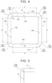
- "Withdrawn toward the central portion of the humidifying membrane 13" means that, as shown in FIG. 4 , the humidifying membrane 13 is exposed around the outer edge portion 14E of the protective film 14 when the protective film 14 provided so as to be stacked on the humidifying membrane 13 is viewed in plan.
- the outer peripheral length of the outer edge portion 14E of the protective film 14 is smaller than the outer peripheral length of the outer edge portion 13E of the humidifying membrane 13.
- the exposed portion of the humidifying membrane 13 between the outer edge portion 13E of the humidifying membrane 13 and the outer edge portion 14E of the protective film 14 is referred to as "close contact region 19."
- the protective film 14 is provided on both the first surface 13A and the second surface 13B of the humidifying membrane 13, as described above. Of the protective films 14 provided on both the first surface 13A and the second surface 13B of the humidifying membrane 13, the protective film 14 on the second surface 13B is provided so as to be withdrawn toward the central portion of the humidifying membrane 13.
- the protective film 14 on the first surface 13A of the humidifying membrane 13 is provided in such a manner that the outer edge portion 14E of the protective film 14 is not withdrawn toward the central portion of the humidifying membrane 13 with respect to the outer edge portion 13E of the humidifying membrane 13.
- the protective film 14 on the first surface 13A of the humidifying membrane 13 is provided in such a manner that the outer edge portion 14E is aligned with the outer edge portion 13E of the humidifying membrane 13.
- the protective film 14 may protrude beyond the outer edge portion 13E of the humidifying membrane 13, as necessary.
- the sealing material 15 is provided along the outer edge portion 13E of the humidifying membrane 13 in such a manner that the sealing material 15 sandwiches the humidifying membrane 13 and the protective films 14.
- the sealing material 15 is provided on the outer peripheral portion of the one surface (front surface 11A) of the first separator 11 except for the dry gas supply path 51 and the humidified air discharge path 52 for the dry gas channels 11C, and is also provided on the outer peripheral portion of the one surface (front surface 12A) of the second separator 12 other than the water-containing gas supply path 61 and a water-containing air discharge path 62 for the water-containing gas channels 12C.
- “sandwich the humidifying membrane 13 and the protective films 14" refers to the state in which the sealing material 15 is located between the protective film 14 and the first separator 11 and between the protective film 14 and the second separator 12 so that the humidifying membrane 13 and the protective films 14 are separated from the outer peripheral portion of the first separator 11 and the outer peripheral portion of the second separator 12.
- the supply port 71 for the dry gas channels 11C in the outer peripheral portion of the one surface of the first separator 11 is a port that communicates with the dry gas supply path 51 and through which the dry gas is supplied to the dry gas channels 11C
- a discharge port 72 in the outer peripheral portion of the one surface of the first separator 11 is a port that communicates with the humidified air discharge path 52 and through which the humidified air is discharged from the dry gas channels 11C.
- the supply port 81 for the water-containing gas channels 12C in the outer peripheral portion of the one surface of the second separator 12 is a port that communicates with the water-containing gas supply path 61 and through which the water-containing gas is supplied to the water-containing gas channels 12C
- a discharge port 82 in the outer peripheral portion of the one surface of the second separator 12 is a port that communicates with the water-containing air discharge path 62 and through which the water-containing air is discharged from the water-containing gas channels 12C.
- the sealing material 15 is provided in the entire periphery other than the dry gas supply path 51, the humidified air discharge path 52, the water-containing gas supply path 61, and the water-containing air discharge path 62 in such a manner that the humidifying membrane 13 and the protective films 14 are separated from the first separator 11 and the second separator 12.
- the sealing material 15 is shown in gray in FIG. 2 .
- the sealing material 15 is provided such that its outer edge is flush with the outer edges of the first separator 11 and the second separator 12.
- the outer edge of the sealing material 15 is shown located slightly inward of the outer edges of the first separator 11 and the second separator 12. However, the outer edge of the sealing material 15 actually is flush with the outer edges of the first separator 11 and the second separator 12.
- an adhesive can be used as such a sealing material 15.
- the sealing material 15 is provided so as to be in direct contact with the humidifying membrane 13 in the close contact region 19 of the humidifying membrane 13 between the outer edge portion 13E of the humidifying membrane 13 and the outer edge portion 14E of the protective film 14. Accordingly, even if the protective film 14 has voids in the thickness direction of the protective film 14, airtightness between the sealing material 15 and the humidifying membrane 13 is improved and sealing is provided between the dry gas channels 11C and the water-containing gas channels 12C, so that the risk of leakage (cross leakage) of air (dry air and humidified air) from the dry gas channels 11C to the water-containing gas channels 12C can be reduced.
- the close contact region 19 of the humidifying membrane 13 is provided on at least either the first surface 13A that is the front surface of the humidifying membrane 13 and the second surface 13B that is the back surface of the humidifying membrane 13.
- the protective film 14 is provided on both the first surface 13A and the second surface 13B of the humidifying membrane 13, but the close contact region 19 is provided only on the second surface 13B.
- the close contact region 19 on the second surface 13B that is subjected to the pressure of the dry air is suitable because the humidifying membrane 13 is less likely to be bent and deformed even when there is a pressure difference between the dry air (high pressure) flowing through the dry gas channels 11C and the water-containing air (low pressure) flowing through the water-containing gas channels 12C.
- the close contact region 19 may be provided on both the first surface 13A and the second surface 13B, or may be provided only on the first surface 13A.
- the close contact region 19 may be provided on the opposite surface of the humidifying membrane 13 from the surface on which the protective film 14 is provided.
- FIG. 4 shows in plan the humidifying membrane 13 and the protective film 14 provided on the second surface 13B of the humidifying membrane 13 in such a manner that the outer edge portion 14E is withdrawn toward the central portion of the humidifying membrane 13 with respect to the outer edge portion 13E of the humidifying membrane 13.
- the humidifying membrane 13 and the protective film 14 provided in the withdrawn state are configured to have a plurality of (in the present embodiment, four) portions that are parallel to each other.
- such parallel portions are denoted by sign P.
- the distance between the outer edge portion 13E of the humidifying membrane 13 and the outer edge portion 14E of the protective film 14 as viewed in plan can thus be made equal in the plurality of parallel portions P.
- the supply port 71, the discharge port 72, the supply port 81, and the discharge port 82 are formed in the corners of the humidifying membrane 13 and the protective film 14 that are portions that are not parallel (not denoted by sign P) (see also FIG. 2 ).
- the distance between the outer edge portion 13E of the humidifying membrane 13 and the outer edge portion 14E of the protective film 14 provided with the sealing material 15 as viewed in plan (width of the close contact region 19) is the same in the entire periphery. Therefore, even if the humidifying membrane 13 expands or contracts due to change in external environment, the protective film 14 can follow such expansion or contraction, so that damage to (e.g., breakage of) the protective film 14 and the humidifying membrane 13 can be prevented. Since the sealing material 15 is uniformly in close contact with the humidifying membrane 13 and the protective film 14 in the entire periphery, the humidifying membrane 13 and the protective film 14 are less likely to wrinkle.
- At least corners 13R of the outer edge portion 13E of the humidifying membrane 13 are formed in a circular arc shape as viewed in plan.
- the sealing material 15 can be more easily provided on the corners 13R.
- the distance between the outer edge portion 13E of the humidifying membrane 13 and the outer edge portion 14E of the protective film 14 be the same in the corners 13R as well. That is, it is preferable to form the protective film 14 in a rectangular shape so that the centers O of the circular arcs of the corners 13R of the humidifying membrane 13 are located at the vertexes of the protective film 14 (see FIG. 5 ), or to form corners 14R of the outer edge portion 14E of the protective film 14 in a circular arc shape so that the centers O of the corners 13R of the humidifying membrane 13 match the centers O of the corners 14R of the protective film 14 (see FIG. 4 ).
- the width of the close contact region 19 where the humidifying membrane 13 is exposed (distance between the outer edge portion 13E of the humidifying membrane 13 and the outer edge portion 14E of the protective film 14) when the protective film 14 provided so as to be stacked on the humidifying membrane 13 is viewed in plan can be made equal in the entire periphery of the humidifying membrane 13 and the protective film 14 including the supply port 71, the discharge port 72, the supply port 81, and the discharge port 82 (not shown in FIG. 4 ).
- the humidifier 1 according to a second embodiment will be described.
- the portions having the same configuration as in the first embodiment are denoted by the same signs as in the first embodiment, and description of the same configuration will be omitted.
- the humidifier 1 according to the present embodiment is different from the first embodiment in the configuration of the humidifying unit 10.
- a reinforcing member 16 is provided between the second separator 12 and the protective film 14 provided on the first surface 13A of the humidifying membrane 13. That is, the reinforcing member 16 is stacked on the opposite side from the humidifying membrane 13 so as to face the protective film 14 provided on the first surface 13A of the humidifying membrane 13.
- the reinforcing member 16 and the protective film 14 are disposed in contact with each other.
- the reinforcing member 16 has the same size as the humidifying membrane 13 and the protective film 14 facing (adjacent to) the reinforcing member 16.
- the protective film 14 on the second surface 13B of the humidifying membrane 13 is provided so as to be withdrawn toward the central portion of the humidifying membrane 13, so that the humidifying membrane 13 has the close contact region 19 only on the second surface 13B.
- resin mesh is used as the reinforcing member 16.
- the reinforcing member 16 is not limited to this, and paper, nonwoven fabric, a porous film, etc. can be used.
- the protective film 14 and the reinforcing member 16 are entirely in contact with each other.
- the protective film 14 and the reinforcing member 16 may be configured to be only partially in contact with each other, for example, only in their central regions.
- the sealing material 15 is provided along the outer edge portion 13E of the humidifying membrane 13 in such a manner that the sealing material 15 sandwiches the humidifying membrane 13, the protective films 14 on both sides thereof, and the reinforcing member 16.
- “sandwich the humidifying membrane 13, the protective films 14 on both sides thereof, and the reinforcing member 16" refers to the state in which the sealing material 15 is located between the protective film 14 on the second surface 13B of the humidifying membrane 13 and the first separator 11 and between the reinforcing member 16 and the second separator 12 so that the humidifying membrane 13, the protective films 14 on both sides thereof, and the reinforcing member 16 are separated from the outer peripheral portion of the first separator 11 and the outer peripheral portion of the second separator 12.
- the dry air flowing through the dry gas channels 11C has been compressed by the compressor 41, and therefore has a higher pressure than the water-containing air flowing through the water-containing gas channels 12C, as described above. Therefore, even when the protective films 14 are provided, the humidifying membrane 13 may be bent and deformed due to the pressure difference between the dry air flowing through the dry gas channels 11C and the water-containing air flowing through the water-containing gas channels 12C.
- Providing the reinforcing member 16 increases the tensile strengths of the humidifying membrane 13 and the protective films 14. Therefore, even when the pressure of the dry air is applied, the humidifying membrane 13 and the protective films 14 are less likely to be bent, so that deformation thereof can be reduced.
- the reinforcing member 16 is provided between the second separator 12 and the protective film 14 on the first surface 13A of the humidifying membrane 13.
- the reinforcing member 16 may be provided between the first separator 11 and the protective film 14 on the second surface 13B of the humidifying membrane 13, or two reinforcing members 16 may be provided so as to face both protective films 14.
- the reinforcing member 16 has the same size as the humidifying membrane 13 and the protective film 14 facing the reinforcing member 16.
- the reinforcing member 16 having the same size as the protective film 14 on the second surface 13B of the humidifying membrane 13, namely having the same size as the humidifying membrane 13, may be provided between the first separator 11 and the protective film 14 on the second surface 13B of the humidifying membrane 13.
- the humidifying membrane 13 and the protective film 14 are described as having the portions P parallel to each other.
- the humidifying membrane 13 and the protective film 14 may be structured so as not to have the portions P parallel to each other.
- the corners 13R of the outer edge portion 13E of the humidifying membrane 13 are described as being formed in a circular arc shape.
- the corners 13R of the outer edge portion 13E of the humidifying membrane 13 may not be formed in a circular arc shape.
- only the corners 14R of the outer edge portion 14E of the protective film 14 may be formed in a circular arc shape.
- the humidifying membrane 13 and the protective films 14 are formed in a quadrilateral shape.
- the humidifying membrane 13 and the protective films 14 may have a triangular shape, or may be formed in a polygonal shape with five or more sides.
- the humidifying membrane 13 and the protective films 14 may be formed in a circular shape.
- the surface 11A of each partition wall that separates adjacent dry gas channels 11C, 11C of the first separator 11 from each other and the surface 12A of each partition wall that separates adjacent water-containing gas channels 12C, 12C of the second separator 12 from each other are in contact with the protective film 14 or the reinforcing member 16 (see FIGS. 3 and 6 to 10).
- Moisture in the gas flowing through the water-containing gas channels 12C can thus be supplied to the dry air flowing through the dry gas channels 11C even in portions facing the surfaces 11A, 12A of the partition walls.
- the present invention can be used for humidifiers for fuel cells that include a humidifying unit for providing moisture contained in water-containing air to dry air to produce humidified air.
Landscapes
- Chemical & Material Sciences (AREA)
- Chemical Kinetics & Catalysis (AREA)
- Life Sciences & Earth Sciences (AREA)
- Engineering & Computer Science (AREA)
- Manufacturing & Machinery (AREA)
- Sustainable Development (AREA)
- Sustainable Energy (AREA)
- Electrochemistry (AREA)
- General Chemical & Material Sciences (AREA)
- Fuel Cell (AREA)
Abstract
Description
- The present invention relates to humidifiers for fuel cells that include a humidifying unit for providing moisture contained in water-containing air to dry air to produce humidified air.
- In recent years, fuel cells have been used. The fuel cells are provided with a humidifier in order to humidify cathode gas to be supplied to the cathode. Some of such humidifiers include a humidifying unit in which separators for guiding gas and water-permeable membranes are alternately arranged. Such a humidifier is described in, for example,
Patent Document 1 shown below. -
Patent Document 1 describes a humidifier for a fuel cell. This humidifier for a fuel cell includes: a humidifying membrane serving as a humidifying member; incoming humidification channels communicating with an air supply passage through which air directed to an air electrode of the fuel cell passes; and outgoing humidification channels communicating with an air off-gas passage through which off-gas after power generation discharged from the air electrode of the fuel cell passes. The incoming humidification channels and the outgoing humidification channels are provided on plate members corresponding to the separators described above, and are arranged so as to face each other with the humidifying membrane interposed therebetween. - Patent Document 1:
Japanese Unexamined Patent Application Publication No. 2003-187839 JP 2003-187839 A - A very thin humidifying membrane is used in the structure in which the incoming humidification channels and the outgoing humidification channels are arranged so as to face each other with the humidifying membrane interposed therebetween, such as the structure in the technique described in
Patent Document 1. Such a thin humidifying membrane is prone to damage when handled in, for example, a manufacturing process. Therefore, there is room for improvement in increasing the strength of the humidifying membrane. - Accordingly, there is a demand for humidifiers for fuel cells whose humidifying membrane is less prone to damage.
- A characteristic configuration of a humidifier for a fuel cell according to the present invention is a humidifier for a fuel cell including a humidifying unit that provides moisture contained in water-containing air to dry air to produce humidified air, wherein the humidifying unit includes: a first separator that is in a form of a plate and that includes a dry gas channel in a central region of one surface of the first separator; a second separator that is in a form of a plate and that includes a water-containing gas channel in a central region of a surface of the second separator that faces the dry gas channel; a humidifying membrane that is located between the dry gas channel and the water-containing gas channel, and that provides moisture contained in gas flowing through the water-containing gas channel to the dry air flowing through the dry gas channel to produce the humidified air; two protective films that are provided so as to be stacked on a front and back of the humidifying membrane, and that reinforce the humidifying membrane; and a sealing material that is provided along a first outer edge portion of the humidifying membrane with the humidifying membrane and the protective films stacked together, and that seals between the dry gas channel and the water-containing gas channel. A second outer edge portion of at least one of the protective films is shorter than the first outer edge portion of the humidifying membrane so that the humidifying membrane has a close contact region between the first outer edge portion and the second outer edge portion.
- With such a characteristic configuration, the protective films can protect the humidifying membrane and reinforce the mechanical strength of the humidifying membrane. The risk of damage during the manufacturing process can thus be reduced. Moreover, adhesion between the humidifying membrane and the sealing material in the close contact region can be increased, so that leakage between the dry gas channel and the water-containing gas channel via the protective film can be prevented.
- It is suitable that a reinforcing member be provided on an opposite side from the humidifying membrane so as to face at least one of the protective films, and that the reinforcing member together with the humidifying membrane and the protective films be sandwiched by the sealing material between the first separator and the second separator.
- With such a configuration, even when the pressure of the dry air flowing through the dry gas channel is applied to the humidifying membrane and the protective films, the humidifying membrane and the protective films are less likely to be bent due to the reinforcing member, so that deformation thereof can be reduced.
- It is suitable that the reinforcing member be provided in contact with the protective film located between the second separator and the humidifying membrane.
- With such a configuration, the humidifying membrane and the protective films are even less likely to be bent, so that deformation thereof can be more effectively reduced.
- It is suitable that the humidifying membrane have the close contact region on at least one of surfaces of the humidifying membrane.
- With such a configuration, leakage between the dry gas channel and the water-containing gas channel via the protective film can be prevented on the surface of the humidifying membrane on which the close contact region is provided.
- It is suitable that the humidifying membrane have the close contact region on the surface that faces the first separator.
- With such a configuration, leakage between the dry gas channel and the water-containing gas channel via the protective film can be prevented on the surface of the humidifying membrane on which the close contact region is provided. When the close contact region is provided on the surface of the humidifying membrane that faces the first separator, the humidifying membrane is less likely to be bent and deformed even when there is a pressure difference between the dry air (high pressure) flowing through the dry gas channel and the water-containing air (low pressure) flowing through the water-containing gas channel.
- It is suitable that the humidifying membrane and the protective film have a plurality of portions parallel to each other, and that the close contact region have a same width in all of the plurality of parallel portions.
- With such a configuration, the distance between the outer edge portion of the protective film and the outer edge portion of the humidifying membrane can be made equal in all of the plurality of parallel portions. Therefore, even if the humidifying membrane expands or contracts due to change in external environment, the protective film can follow such expansion or contraction, so that separation of the protective film can be prevented. Moreover, since the sealing material is uniformly in close contact with the humidifying membrane and the protective film, the humidifying membrane and the protective film are less likely to wrinkle.
- It is suitable that at least corners of the outer edge portion of the humidifying membrane have a circular arc shape, and that the width of the close contact region in the corners be equal to the width of the close contact region in the plurality of parallel portions so that the close contact region has the same width in an entire periphery of the humidifying membrane.
- With such a configuration, the distance between the outer edge portion of the protective film and the outer edge portion of the humidifying membrane can be made equal in the entire periphery. Therefore, even if the humidifying membrane expands or contracts due to change in external environment, the protective film can follow such expansion or contraction, so that separation of the protective film can be prevented. Since the sealing material is uniformly in close contact with the humidifying membrane and the protective film in the entire periphery, the humidifying membrane and the protective film are less likely to wrinkle.
- It is suitable that corners of the second outer edge portion of the protective film have a circular arc shape.
- With such a configuration, the distance between the outer edge portion of the protective film and the outer edge portion of the humidifying membrane can be made equal in the entire periphery. Therefore, even if the humidifying membrane expands or contracts due to change in external environment, the protective film can follow such expansion or contraction, so that separation of the protective film can be prevented. Since the sealing material is uniformly in close contact with the humidifying membrane and the protective film in the entire periphery, the humidifying membrane and the protective film are less likely to wrinkle.
-
- [
FIG. 1] FIG. 1 is a perspective view of a humidifier for a fuel cell. - [
FIG. 2] FIG. 2 is a diagram showing flow paths communicating with the humidifier for a fuel cell. - [
FIG. 3] FIG. 3 is a partial side sectional view of a humidifying unit according to a first embodiment. - [
FIG. 4] FIG. 4 is a plan view of a protective film provided on a humidifying membrane. - [
FIG. 5] FIG. 5 is another example of the protective film provided on the humidifying membrane. - [
FIG. 6] FIG. 6 is a partial side sectional view of a humidifying unit according to a second embodiment. - [
FIG. 7] FIG. 7 is a partial side sectional view of a humidifying unit according to a modification. - [
FIG. 8] FIG. 8 is a partial side sectional view of a humidifying unit according to a modification. - [
FIG. 9] FIG. 9 is a partial side sectional view of a humidifying unit according to a modification. - [
FIG. 10] FIG. 10 is a partial side sectional view of a humidifying unit according to a modification. - A humidifier for a fuel cell (hereinafter referred to as "humidifier") according to the present invention is configured to protect and reinforce a humidifying membrane. A
humidifier 1 of an embodiment will be described below. -
FIG. 1 is a perspective view of ahumidifier 1 according to a first embodiment.FIG. 2 is a diagram showing flow paths communicating with thehumidifier 1.FIG. 3 is a side sectional view of part of a humidifyingunit 10. Thehumidifier 1 includes afirst plate 2, asecond plate 3, and thehumidifying unit 10. Thehumidifying unit 10 is provided so as to be sandwiched between thefirst plate 2 and thesecond plate 3. As will be described in detail later, the humidifyingunit 10 provides moisture contained in water-containing air to dry air to produce humidified air. As shown inFIG. 3 , thehumidifying unit 10 is composed of a stack of afirst separator 11, asecond separator 12, ahumidifying membrane 13, andprotective films 14. Thehumidifying unit 10 is provided in such a manner that thesecond separator 12, theprotective film 14, thehumidifying membrane 13, theprotective film 14, and thefirst separator 11 are stacked in this order between thefirst plate 2 and thesecond plate 3, with the stack being pressed in the stacking direction. Thehumidifying unit 10 is composed of a stack of a plurality of the stacks shown inFIG. 3 . - As shown in
FIG. 2 , thehumidifier 1 is provided with a drygas supply port 21, a humidifiedgas discharge port 22, a water-containinggas supply port 31, and a water-containinggas discharge port 32. In the present embodiment, thehumidifying unit 10 has a quadrilateral shape as viewed in plan. The drygas supply port 21 and the humidifiedgas discharge port 22 are located so as to face each other along a diagonal line of the quadrilateral shape, and the water-containinggas supply port 31 and the water-containinggas discharge port 32 are located so as to face each other along a diagonal line of the quadrilateral square. - In the present embodiment, air (example of "dry air") compressed by a
compressor 41 is supplied to the drygas supply port 21 of thehumidifier 1 via avalve 42. The dry air supplied to the drygas supply port 21 is humidified while flowing throughdry gas channels 11C that will be described later, and is discharged as humidified air from the humidifiedgas discharge port 22. The humidified air discharged from the humidifiedgas discharge port 22 is introduced into a cathodegas supply path 43B and supplied to afuel cell 43. Thefuel cell 43 is supplied with fuel gas containing hydrogen gas and air containing oxygen gas (corresponding to the above "dry air") and generates electricity. By this power generation, thefuel cell 43 discharges water-containing gas (example of "water-containing air") containing a large amount of water in the form of water vapor. This water-containing gas is supplied to the water-containinggas supply port 31 through a cathode off-gas discharge path 43A. The water-containing gas supplied to the water-containinggas supply port 31 humidifies the dry air flowing through thedry gas channels 11C as it flows through water-containinggas channels 12C that will be described later. The water-containing gas is then discharged from the water-containinggas discharge port 32. - As shown in
FIG. 3 , thefirst separator 11 has thedry gas channels 11C in a central region of its one surface. Thefirst separator 11 is in the form of a plate. Of afront surface 11A and aback surface 11B out of the surfaces of the plate-likefirst separator 11, the one surface is thefront surface 11A. Therefore, when thefirst separator 11 is divided into an outer peripheral portion and a central portion as viewed in plan, the central region of the one surface is the region of the central portion. Accordingly, thefirst separator 11 has thedry gas channels 11C in the central region of thefront surface 11A as viewed in plan. A sealingmaterial 15, which will be described later, is provided on the outer peripheral portion of thefront surface 11A of thefirst separator 11, as viewed in plan. In order to facilitate understanding, in the present embodiment, the region of thefront surface 11A where the sealingmaterial 15 is provided is defined as the outer peripheral portion, and the region of thefront surface 11A where thedry gas channels 11C are formed is defined as the central portion, as viewed in plan. Although only onefirst separator 11 is shown inFIG. 3 , thehumidifying unit 10 includes a plurality of thefirst separators 11, and as shown inFIG. 2 , theirdry gas channels 11C are configured to communicate with the drygas supply port 21 through a drygas supply path 51 and asupply port 71. With this configuration, the dry air from thecompressor 41 can be introduced into thedry gas channels 11C as described above. Thefirst separator 11 may have thedry gas channels 11C or the water-containinggas channels 12C in the central region of theback surface 11B, in addition to thefront surface 11A. - The
second separator 12 has the water-containinggas channels 12C in a central region of one surface thereof. Thesecond separator 12 is in the form of a plate. Of afront surface 12A and aback surface 12B out of the surfaces of the plate-likesecond separator 12, the one surface is thefront surface 12A. Therefore, when thesecond separator 12 is divided into an outer peripheral portion and a central portion as viewed in plan, the central region of the one surface is the region of the central portion. Accordingly, thesecond separator 12 has the water-containinggas channels 12C in the central region of thefront surface 12A as viewed in plan. The sealingmaterial 15, which will be described later, is also provided on the outer peripheral portion of thefront surface 12A of thesecond separator 12, as viewed in plan. In order to facilitate understanding, in the present embodiment, the region of thefront surface 12A where the sealingmaterial 15 is provided is defined as the outer peripheral portion, and the region of thefront surface 12A where the water-containinggas channels 12C are formed is defined as the central portion, as viewed in plan. Although only onesecond separator 12 is shown inFIG. 3 , thehumidifying unit 10 also includes a plurality of thesecond separators 12, and as shown inFIG. 2 , their water-containinggas channels 12C are configured to communicate with the water-containinggas supply port 31 through a water-containinggas supply path 61 and asupply port 81. With this configuration, the water-containing gas from thefuel cell 43 can be introduced. Thesecond separator 12 may have the water-containinggas channels 12C or thedry gas channels 11C in the central region of theback surface 12B, in addition to thefront surface 12A. - As shown in
FIG. 3 , thehumidifying membrane 13 is located between thedry gas channels 11C and the water-containinggas channels 12C in the stacking direction. "Between thedry gas channels 11C and the water-containinggas channels 12C" means between the central region of thefirst separator 11 and the central region of thesecond separator 12 described above. Therefore, thehumidifying membrane 13 is located between the central region of thefirst separator 11 and the central region of thesecond separator 12. That is, thedry gas channels 11C and the water-containinggas channels 12C face each other with thehumidifying membrane 13 interposed therebetween. Thehumidifying unit 10 also includes a plurality of thehumidifying membranes 13. - Such a
humidifying membrane 13 provides moisture contained in the gas flowing through the water-containinggas channels 12C to the dry air flowing through thedry gas channels 11C to produce humidified air. The dry air flowing through thedry gas channels 11C is dry gas supplied from thecompressor 41 to thedry gas channels 11C through thevalve 42, the drygas supply port 21, and the drygas supply path 51. The gas flowing through the water-containinggas channels 12C is water-containing gas supplied from the cathode off-gas discharge path 43A to the water-containinggas channels 12C. Therefore, thehumidifying membrane 13 provides moisture contained in the water-containing gas flowing from thefuel cell 43 through the cathode off-gas discharge path 43A and the water-containinggas supply port 31 to the dry gas supplied from thecompressor 41 through thevalve 42, the drygas supply port 21, and the drygas supply path 51 to produce humidified air. Since the method of providing moisture to dry air to produce humidified gas (example of "humidified air") is well known in the art, description thereof will be omitted. The humidified gas thus produced is introduced into the cathodegas supply path 43B through a humidifiedair discharge path 52 and the humidifiedgas discharge port 22 and is supplied to thefuel cell 43. - As shown in
FIG. 3 , theprotective films 14 are provided so as to be stacked on thehumidifying membrane 13, and reinforce thehumidifying membrane 13. "Provided so as to be stacked on thehumidifying membrane 13" means that theprotective film 14 is provided so as to be bonded to at least either afirst surface 13A that is a front surface of thehumidifying membrane 13 and asecond surface 13B that is a back surface of thehumidifying membrane 13. In the present embodiment, theprotective film 14 is provided on both thefirst surface 13A and thesecond surface 13B (front and back) of thehumidifying membrane 13. For example, nonwoven fabric is used as theprotective film 14. However, theprotective film 14 is not limited to this, and paper, mesh, a porous film, etc. can be used. Theprotective film 14 can thus protect thehumidifying membrane 13 that is a thin membrane (e.g., several micrometers thick) and reinforce the mechanical strength of thehumidifying membrane 13, and can improve ease of handling in, for example, a manufacturing process and prevent damage. - The
protective films 14 are provided in such a manner that an outer edge portion (example of the second outer edge portion) 14E of at least one of theprotective films 14 is withdrawn toward the central portion of thehumidifying membrane 13 with respect to an outer edge portion (example of the first outer edge portion) 13E of thehumidifying membrane 13. Theouter edge portion 14E of theprotective film 14 is an edge portion (outer end portion) in the outer peripheral portion of theprotective film 14 described above. "Withdrawn toward the central portion of thehumidifying membrane 13" means that, as shown inFIG. 4 , thehumidifying membrane 13 is exposed around theouter edge portion 14E of theprotective film 14 when theprotective film 14 provided so as to be stacked on thehumidifying membrane 13 is viewed in plan. At this time, the outer peripheral length of theouter edge portion 14E of theprotective film 14 is smaller than the outer peripheral length of theouter edge portion 13E of thehumidifying membrane 13. In the present embodiment, the exposed portion of thehumidifying membrane 13 between theouter edge portion 13E of thehumidifying membrane 13 and theouter edge portion 14E of theprotective film 14 is referred to as "close contact region 19." In the present embodiment, theprotective film 14 is provided on both thefirst surface 13A and thesecond surface 13B of thehumidifying membrane 13, as described above. Of theprotective films 14 provided on both thefirst surface 13A and thesecond surface 13B of thehumidifying membrane 13, theprotective film 14 on thesecond surface 13B is provided so as to be withdrawn toward the central portion of thehumidifying membrane 13. On the other hand, theprotective film 14 on thefirst surface 13A of thehumidifying membrane 13 is provided in such a manner that theouter edge portion 14E of theprotective film 14 is not withdrawn toward the central portion of thehumidifying membrane 13 with respect to theouter edge portion 13E of thehumidifying membrane 13. In the present embodiment, theprotective film 14 on thefirst surface 13A of thehumidifying membrane 13 is provided in such a manner that theouter edge portion 14E is aligned with theouter edge portion 13E of thehumidifying membrane 13. Theprotective film 14 may protrude beyond theouter edge portion 13E of thehumidifying membrane 13, as necessary. - The sealing
material 15 is provided along theouter edge portion 13E of thehumidifying membrane 13 in such a manner that the sealingmaterial 15 sandwiches thehumidifying membrane 13 and theprotective films 14. Specifically, the sealingmaterial 15 is provided on the outer peripheral portion of the one surface (front surface 11A) of thefirst separator 11 except for the drygas supply path 51 and the humidifiedair discharge path 52 for thedry gas channels 11C, and is also provided on the outer peripheral portion of the one surface (front surface 12A) of thesecond separator 12 other than the water-containinggas supply path 61 and a water-containingair discharge path 62 for the water-containinggas channels 12C. In the present embodiment, "sandwich thehumidifying membrane 13 and theprotective films 14" refers to the state in which the sealingmaterial 15 is located between theprotective film 14 and thefirst separator 11 and between theprotective film 14 and thesecond separator 12 so that thehumidifying membrane 13 and theprotective films 14 are separated from the outer peripheral portion of thefirst separator 11 and the outer peripheral portion of thesecond separator 12. Thesupply port 71 for thedry gas channels 11C in the outer peripheral portion of the one surface of thefirst separator 11 is a port that communicates with the drygas supply path 51 and through which the dry gas is supplied to thedry gas channels 11C, and adischarge port 72 in the outer peripheral portion of the one surface of thefirst separator 11 is a port that communicates with the humidifiedair discharge path 52 and through which the humidified air is discharged from thedry gas channels 11C. Thesupply port 81 for the water-containinggas channels 12C in the outer peripheral portion of the one surface of thesecond separator 12 is a port that communicates with the water-containinggas supply path 61 and through which the water-containing gas is supplied to the water-containinggas channels 12C, and adischarge port 82 in the outer peripheral portion of the one surface of thesecond separator 12 is a port that communicates with the water-containingair discharge path 62 and through which the water-containing air is discharged from the water-containinggas channels 12C. - In the present embodiment, the sealing
material 15 is provided in the entire periphery other than the drygas supply path 51, the humidifiedair discharge path 52, the water-containinggas supply path 61, and the water-containingair discharge path 62 in such a manner that thehumidifying membrane 13 and theprotective films 14 are separated from thefirst separator 11 and thesecond separator 12. The sealingmaterial 15 is shown in gray inFIG. 2 . As shown inFIG. 3 , the sealingmaterial 15 is provided such that its outer edge is flush with the outer edges of thefirst separator 11 and thesecond separator 12. InFIG. 2 , the outer edge of the sealingmaterial 15 is shown located slightly inward of the outer edges of thefirst separator 11 and thesecond separator 12. However, the outer edge of the sealingmaterial 15 actually is flush with the outer edges of thefirst separator 11 and thesecond separator 12. For example, an adhesive can be used as such a sealingmaterial 15. - The sealing
material 15 is provided so as to be in direct contact with thehumidifying membrane 13 in theclose contact region 19 of thehumidifying membrane 13 between theouter edge portion 13E of thehumidifying membrane 13 and theouter edge portion 14E of theprotective film 14. Accordingly, even if theprotective film 14 has voids in the thickness direction of theprotective film 14, airtightness between the sealingmaterial 15 and thehumidifying membrane 13 is improved and sealing is provided between thedry gas channels 11C and the water-containinggas channels 12C, so that the risk of leakage (cross leakage) of air (dry air and humidified air) from thedry gas channels 11C to the water-containinggas channels 12C can be reduced. - The
close contact region 19 of thehumidifying membrane 13 is provided on at least either thefirst surface 13A that is the front surface of thehumidifying membrane 13 and thesecond surface 13B that is the back surface of thehumidifying membrane 13. In the present embodiment, theprotective film 14 is provided on both thefirst surface 13A and thesecond surface 13B of thehumidifying membrane 13, but theclose contact region 19 is provided only on thesecond surface 13B. Normally, the dry air flowing through thedry gas channels 11C has been compressed by thecompressor 41, and therefore has a higher pressure than the water-containing air flowing through the water-containinggas channels 12C. Accordingly, providing theclose contact region 19 on thesecond surface 13B that is subjected to the pressure of the dry air is suitable because thehumidifying membrane 13 is less likely to be bent and deformed even when there is a pressure difference between the dry air (high pressure) flowing through thedry gas channels 11C and the water-containing air (low pressure) flowing through the water-containinggas channels 12C. It should be understood that theclose contact region 19 may be provided on both thefirst surface 13A and thesecond surface 13B, or may be provided only on thefirst surface 13A. Moreover, in the case where theprotective film 14 is provided on only either thefirst surface 13A or thesecond surface 13B of thehumidifying membrane 13, and theouter edge portion 14E of theprotective film 14 placed on only one surface of thehumidifying membrane 13 is aligned with, or protrudes beyond, theouter edge portion 13E of thehumidifying membrane 13, theclose contact region 19 may be provided on the opposite surface of thehumidifying membrane 13 from the surface on which theprotective film 14 is provided. -
FIG. 4 shows in plan thehumidifying membrane 13 and theprotective film 14 provided on thesecond surface 13B of thehumidifying membrane 13 in such a manner that theouter edge portion 14E is withdrawn toward the central portion of thehumidifying membrane 13 with respect to theouter edge portion 13E of thehumidifying membrane 13. In the present embodiment, thehumidifying membrane 13 and theprotective film 14 provided in the withdrawn state are configured to have a plurality of (in the present embodiment, four) portions that are parallel to each other. InFIG. 4 , such parallel portions are denoted by sign P. The distance between theouter edge portion 13E of thehumidifying membrane 13 and theouter edge portion 14E of theprotective film 14 as viewed in plan (width of the close contact region 19) can thus be made equal in the plurality of parallel portions P. Thesupply port 71, thedischarge port 72, thesupply port 81, and thedischarge port 82 are formed in the corners of thehumidifying membrane 13 and theprotective film 14 that are portions that are not parallel (not denoted by sign P) (see alsoFIG. 2 ). The distance between theouter edge portion 13E of thehumidifying membrane 13 and theouter edge portion 14E of theprotective film 14 provided with the sealingmaterial 15 as viewed in plan (width of the close contact region 19) is the same in the entire periphery. Therefore, even if thehumidifying membrane 13 expands or contracts due to change in external environment, theprotective film 14 can follow such expansion or contraction, so that damage to (e.g., breakage of) theprotective film 14 and thehumidifying membrane 13 can be prevented. Since the sealingmaterial 15 is uniformly in close contact with thehumidifying membrane 13 and theprotective film 14 in the entire periphery, thehumidifying membrane 13 and theprotective film 14 are less likely to wrinkle. - Moreover, in the present embodiment, as shown in
FIGS. 4 and 5 , atleast corners 13R of theouter edge portion 13E of thehumidifying membrane 13 are formed in a circular arc shape as viewed in plan. When part of thecorners 13R of theouter edge portion 13E of thehumidifying membrane 13 does not overlap thesupply port 71, thedischarge port 72, thesupply port 81, and thedischarge port 82, or when thesupply port 71, thedischarge port 72, thesupply port 81, and thedischarge port 82 are formed in portions other than thecorners 13R (portions denoted by sign P), the sealingmaterial 15 can be more easily provided on thecorners 13R. Therefore, it is preferable that the distance between theouter edge portion 13E of thehumidifying membrane 13 and theouter edge portion 14E of the protective film 14 (width of the close contact region 19) be the same in thecorners 13R as well. That is, it is preferable to form theprotective film 14 in a rectangular shape so that the centers O of the circular arcs of thecorners 13R of thehumidifying membrane 13 are located at the vertexes of the protective film 14 (seeFIG. 5 ), or to formcorners 14R of theouter edge portion 14E of theprotective film 14 in a circular arc shape so that the centers O of thecorners 13R of thehumidifying membrane 13 match the centers O of thecorners 14R of the protective film 14 (seeFIG. 4 ). With this configuration, the width of theclose contact region 19 where thehumidifying membrane 13 is exposed (distance between theouter edge portion 13E of thehumidifying membrane 13 and theouter edge portion 14E of the protective film 14) when theprotective film 14 provided so as to be stacked on thehumidifying membrane 13 is viewed in plan can be made equal in the entire periphery of thehumidifying membrane 13 and theprotective film 14 including thesupply port 71, thedischarge port 72, thesupply port 81, and the discharge port 82 (not shown inFIG. 4 ). - Next, the
humidifier 1 according to a second embodiment will be described. In the description of the present embodiment, the portions having the same configuration as in the first embodiment are denoted by the same signs as in the first embodiment, and description of the same configuration will be omitted. Thehumidifier 1 according to the present embodiment is different from the first embodiment in the configuration of thehumidifying unit 10. - As shown in
FIG. 6 , in the present embodiment, a reinforcingmember 16 is provided between thesecond separator 12 and theprotective film 14 provided on thefirst surface 13A of thehumidifying membrane 13. That is, the reinforcingmember 16 is stacked on the opposite side from thehumidifying membrane 13 so as to face theprotective film 14 provided on thefirst surface 13A of thehumidifying membrane 13. The reinforcingmember 16 and theprotective film 14 are disposed in contact with each other. In the present embodiment, the reinforcingmember 16 has the same size as thehumidifying membrane 13 and theprotective film 14 facing (adjacent to) the reinforcingmember 16. On the other hand, theprotective film 14 on thesecond surface 13B of thehumidifying membrane 13 is provided so as to be withdrawn toward the central portion of thehumidifying membrane 13, so that thehumidifying membrane 13 has theclose contact region 19 only on thesecond surface 13B. For example, resin mesh is used as the reinforcingmember 16. However, the reinforcingmember 16 is not limited to this, and paper, nonwoven fabric, a porous film, etc. can be used. In the present embodiment, theprotective film 14 and the reinforcingmember 16 are entirely in contact with each other. However, theprotective film 14 and the reinforcingmember 16 may be configured to be only partially in contact with each other, for example, only in their central regions. - The sealing
material 15 is provided along theouter edge portion 13E of thehumidifying membrane 13 in such a manner that the sealingmaterial 15 sandwiches thehumidifying membrane 13, theprotective films 14 on both sides thereof, and the reinforcingmember 16. In the present embodiment, "sandwich thehumidifying membrane 13, theprotective films 14 on both sides thereof, and the reinforcingmember 16" refers to the state in which the sealingmaterial 15 is located between theprotective film 14 on thesecond surface 13B of thehumidifying membrane 13 and thefirst separator 11 and between the reinforcingmember 16 and thesecond separator 12 so that thehumidifying membrane 13, theprotective films 14 on both sides thereof, and the reinforcingmember 16 are separated from the outer peripheral portion of thefirst separator 11 and the outer peripheral portion of thesecond separator 12. - Normally, the dry air flowing through the
dry gas channels 11C has been compressed by thecompressor 41, and therefore has a higher pressure than the water-containing air flowing through the water-containinggas channels 12C, as described above. Therefore, even when theprotective films 14 are provided, thehumidifying membrane 13 may be bent and deformed due to the pressure difference between the dry air flowing through thedry gas channels 11C and the water-containing air flowing through the water-containinggas channels 12C. Providing the reinforcingmember 16 increases the tensile strengths of thehumidifying membrane 13 and theprotective films 14. Therefore, even when the pressure of the dry air is applied, thehumidifying membrane 13 and theprotective films 14 are less likely to be bent, so that deformation thereof can be reduced. - In the present embodiment, the reinforcing
member 16 is provided between thesecond separator 12 and theprotective film 14 on thefirst surface 13A of thehumidifying membrane 13. However, the reinforcingmember 16 may be provided between thefirst separator 11 and theprotective film 14 on thesecond surface 13B of thehumidifying membrane 13, or two reinforcingmembers 16 may be provided so as to face bothprotective films 14. In the present embodiment, the reinforcingmember 16 has the same size as thehumidifying membrane 13 and theprotective film 14 facing the reinforcingmember 16. - Contrary to
FIG. 6 , in the case where theprotective film 14 on thesecond surface 13B of thehumidifying membrane 13 has the same size as thehumidifying membrane 13 and theprotective film 14 on thefirst surface 13A of thehumidifying membrane 13 is provided so as to be withdrawn toward the central portion of thehumidifying membrane 13 so that thehumidifying membrane 13 has theclose contact region 19 only on thefirst surface 13A, the reinforcingmember 16 having the same size as theprotective film 14 on thesecond surface 13B of thehumidifying membrane 13, namely having the same size as thehumidifying membrane 13, may be provided between thefirst separator 11 and theprotective film 14 on thesecond surface 13B of thehumidifying membrane 13. - The following modifications will be described with reference to the drawing of the second embodiment, but can also be similarly applied to the first embodiment.
- (1) As shown in
FIG. 7 , in the configuration of the second embodiment, the sealingmaterial 15 covers anedge 11F of thefirst separator 11 that forms thedry gas channel 11C and anedge 12F of thesecond separator 12 that forms the water-containinggas channel 12C. Theprotective films 14 and the reinforcingmember 16 can thus be prevented from being torn due to them getting caught on theedges - (2) As shown in
FIG. 8 , awall 11D is formed in the outer edge of thefirst separator 11 and awall 12D is formed in the outer edge of thesecond separator 12 so that thewalls material 15 is provided so as to cover theedges material 15 can thus be prevented from leaking to the outside of thefirst separator 11 and thesecond separator 12, and theprotective films 14 and the reinforcingmember 16 can be prevented from being torn by theedges - (3) As shown in
FIG. 9 , steps 11E, 12E are provided in the outer peripheral portion of thefirst separator 11 and the outer peripheral portion of thesecond separator 12, respectively, so that theprotective film 14 is located in thestep 11E and the reinforcingmember 16 is located in thestep 12E. Thehumidifying membrane 13, theprotective films 14, and the reinforcingmember 16 can thus be easily positioned with respect to thefirst separator 11 and thesecond separator 12. - (4) As shown in
FIG. 10 , thesteps material 15 to flow therein so that this sealingmaterial 15 covers theedge 11F of thefirst separator 11 that forms thedry gas channel 11C and theedge 12F of thesecond separator 12 that forms the water-containinggas channel 12C. Moreover, thewall 11D is formed in the outer edge of thefirst separator 11 and thewall 12D is formed in the outer edge of thesecond separator 12 so that thewalls protective films 14 and the reinforcingmember 16 can thus be prevented from being torn by theedges material 15 can be prevented from leaking to the outside of thefirst separator 11 and thesecond separator 12. Furthermore, with thesteps humidifying membrane 13, theprotective films 14, and the reinforcingmember 16 can be easily positioned with respect to thefirst separator 11 and thesecond separator 12. - In the above embodiments, the
humidifying membrane 13 and theprotective film 14 are described as having the portions P parallel to each other. However, thehumidifying membrane 13 and theprotective film 14 may be structured so as not to have the portions P parallel to each other. - In the above embodiments, at least the
corners 13R of theouter edge portion 13E of thehumidifying membrane 13 are described as being formed in a circular arc shape. However, thecorners 13R of theouter edge portion 13E of thehumidifying membrane 13 may not be formed in a circular arc shape. In this case, only thecorners 14R of theouter edge portion 14E of theprotective film 14 may be formed in a circular arc shape. - The above embodiments illustrate examples in which the
humidifying membrane 13 and theprotective films 14 are formed in a quadrilateral shape. However, thehumidifying membrane 13 and theprotective films 14 may have a triangular shape, or may be formed in a polygonal shape with five or more sides. Alternatively, thehumidifying membrane 13 and theprotective films 14 may be formed in a circular shape. - In the above embodiments, in the central region that is the region located inside the region where the sealing
material 15 is provided, thesurface 11A of each partition wall that separates adjacentdry gas channels first separator 11 from each other and thesurface 12A of each partition wall that separates adjacent water-containinggas channels second separator 12 from each other are in contact with theprotective film 14 or the reinforcing member 16 (seeFIGS. 3 and6 to 10). However, there may be clearance between either or both of thesurfaces protective film 14 or the reinforcingmember 16. Moisture in the gas flowing through the water-containinggas channels 12C can thus be supplied to the dry air flowing through thedry gas channels 11C even in portions facing thesurfaces - The configurations according to the above embodiments and modifications can be combined in any way possible.
- The present invention can be used for humidifiers for fuel cells that include a humidifying unit for providing moisture contained in water-containing air to dry air to produce humidified air.
-
- 1: Humidifier (Humidifier for Fuel Cell)
- 10: Humidifying Unit
- 11: First Separator
- 11A: Front Surface (One Surface)
- 11C: Dry Gas Channel
- 12: Second Separator
- 12A: Front Surface (One Surface)
- 12C: Water-Containing Gas Channel
- 13: Humidifying Membrane
- 13E: Outer Edge Portion (First Outer Edge Portion)
- 13R: Corner
- 14: Protective Film
- 14E: Outer Edge Portion (Second Outer Edge Portion)
- 15: Sealing Material
- 16: Reinforcing Member
- 19: Close Contact Region
- 71: Supply Port
- 72: Discharge Port
- 81: Supply Port
- 82: Discharge Port
- P: Parallel Portion
Claims (8)
- A humidifier for a fuel cell, the humidifier comprising a humidifying unit that provides moisture contained in water-containing air to dry air to produce humidified air, whereinthe humidifying unit includesa first separator that is in a form of a plate and that includes a dry gas channel in a central region of one surface of the first separator,a second separator that is in a form of a plate and that includes a water-containing gas channel in a central region of a surface of the second separator that faces the dry gas channel,a humidifying membrane that is located between the dry gas channel and the water-containing gas channel, and that provides moisture contained in gas flowing through the water-containing gas channel to the dry air flowing through the dry gas channel to produce the humidified air,two protective films that are provided so as to be stacked on a front and back of the humidifying membrane, and that reinforce the humidifying membrane, anda sealing material that is provided along a first outer edge portion of the humidifying membrane with the humidifying membrane and the protective films stacked together, and that seals between the dry gas channel and the water-containing gas channel, anda second outer edge portion of at least one of the protective films is shorter than the first outer edge portion of the humidifying membrane so that the humidifying membrane has a close contact region between the first outer edge portion and the second outer edge portion.
- The humidifier for a fuel cell according to claim 1, whereina reinforcing member is provided on an opposite side from the humidifying membrane so as to face at least one of the protective films, andthe reinforcing member together with the humidifying membrane and the protective films is sandwiched by the sealing material between the first separator and the second separator.
- The humidifier for a fuel cell according to claim 2, wherein the reinforcing member is provided in contact with the protective film located between the second separator and the humidifying membrane.
- The humidifier for a fuel cell according to any one of claims 1 to 3, wherein the humidifying membrane has the close contact region on at least one of surfaces of the humidifying membrane.
- The humidifier for a fuel cell according to claim 4, wherein the humidifying membrane has the close contact region on the surface that faces the first separator.
- The humidifier for a fuel cell according to any one of claims 1 to 5, wherein the humidifying membrane and the protective film have a plurality of portions parallel to each other, and the close contact region has a same width in all of the plurality of parallel portions.
- The humidifier for a fuel cell according to claim 6, wherein at least corners of the first outer edge portion of the humidifying membrane have a circular arc shape, and the width of the close contact region in the corners is equal to the width of the close contact region in the plurality of parallel portions so that the close contact region has the same width in an entire periphery of the humidifying membrane.
- The humidifier for a fuel cell according to claim 7, wherein corners of the second outer edge portion of the protective film have a circular arc shape.
Applications Claiming Priority (2)
| Application Number | Priority Date | Filing Date | Title |
|---|---|---|---|
| JP2020195803 | 2020-11-26 | ||
| PCT/JP2021/043473 WO2022114147A1 (en) | 2020-11-26 | 2021-11-26 | Humidifier for fuel cell |
Publications (2)
| Publication Number | Publication Date |
|---|---|
| EP4254570A1 true EP4254570A1 (en) | 2023-10-04 |
| EP4254570A4 EP4254570A4 (en) | 2024-05-01 |
Family
ID=81754453
Family Applications (1)
| Application Number | Title | Priority Date | Filing Date |
|---|---|---|---|
| EP21898119.9A Pending EP4254570A4 (en) | 2020-11-26 | 2021-11-26 | FUEL CELL HUMIDIFIER |
Country Status (5)
| Country | Link |
|---|---|
| US (1) | US12683173B2 (en) |
| EP (1) | EP4254570A4 (en) |
| JP (1) | JP7425424B2 (en) |
| CN (1) | CN116438688B (en) |
| WO (1) | WO2022114147A1 (en) |
Families Citing this family (1)
| Publication number | Priority date | Publication date | Assignee | Title |
|---|---|---|---|---|
| JP2024052033A (en) * | 2022-09-30 | 2024-04-11 | 株式会社アイシン | Humidifier for fuel cells |
Family Cites Families (9)
| Publication number | Priority date | Publication date | Assignee | Title |
|---|---|---|---|---|
| JP3881546B2 (en) | 2001-12-17 | 2007-02-14 | アイシン精機株式会社 | Humidifier for fuel cell |
| JP4062198B2 (en) * | 2003-07-30 | 2008-03-19 | トヨタ自動車株式会社 | Humidifier for fuel cell |
| JP2006156099A (en) * | 2004-11-29 | 2006-06-15 | Mitsubishi Electric Corp | Humidifier and method for manufacturing the same |
| JP4542029B2 (en) * | 2005-12-14 | 2010-09-08 | 三菱電機株式会社 | humidifier |
| JP4957365B2 (en) * | 2007-05-08 | 2012-06-20 | パナソニック株式会社 | Fuel cell device |
| JP2009199741A (en) * | 2008-02-19 | 2009-09-03 | Toyota Motor Corp | Fuel cell, and humidifier |
| US9553327B2 (en) * | 2014-12-30 | 2017-01-24 | GM Global Technology Operations LLC | Grafted functional groups on expanded tetrafluoroethylene (ePTFE) support for fuel cell and water transport membranes |
| DE202016100670U1 (en) * | 2016-02-10 | 2017-05-11 | Reinz-Dichtungs-Gmbh | Flow plate for a humidifier |
| CN211265624U (en) * | 2019-01-30 | 2020-08-14 | 深圳伊腾迪新能源有限公司 | Novel fuel cell gas humidifier |
-
2021
- 2021-11-26 WO PCT/JP2021/043473 patent/WO2022114147A1/en not_active Ceased
- 2021-11-26 JP JP2022565464A patent/JP7425424B2/en active Active
- 2021-11-26 US US18/249,276 patent/US12683173B2/en active Active
- 2021-11-26 CN CN202180075979.7A patent/CN116438688B/en active Active
- 2021-11-26 EP EP21898119.9A patent/EP4254570A4/en active Pending
Also Published As
| Publication number | Publication date |
|---|---|
| JP7425424B2 (en) | 2024-01-31 |
| US12683173B2 (en) | 2026-07-14 |
| CN116438688B (en) | 2026-05-26 |
| EP4254570A4 (en) | 2024-05-01 |
| JPWO2022114147A1 (en) | 2022-06-02 |
| WO2022114147A1 (en) | 2022-06-02 |
| CN116438688A (en) | 2023-07-14 |
| US20230395828A1 (en) | 2023-12-07 |
Similar Documents
| Publication | Publication Date | Title |
|---|---|---|
| KR101763662B1 (en) | Seal for solid polymer electrolyte fuel cell | |
| JP7022023B2 (en) | Power generation cell | |
| US6815115B2 (en) | Fuel cell and fuel cell stack | |
| JP3648128B2 (en) | Fuel cell | |
| CN107425213B (en) | The fuel cell | |
| US20030087140A1 (en) | Fuel cell | |
| CN102939678A (en) | fuel cell unit | |
| CN102906920A (en) | Solid oxide fuel cell | |
| CN110224162A (en) | Equip the membrane electrode assembly and fuel cell of frame | |
| MXPA06011687A (en) | Fuel cell gas distribution. | |
| JP2022022636A (en) | Metal separator and fuel cell stack | |
| EP4266435A1 (en) | Fuel cell membrane humidifier | |
| CN101138117B (en) | Fuel cell and separator for fuel cell | |
| CN103682391B (en) | Fuel cell | |
| JP5087863B2 (en) | Fuel cell | |
| US20230395828A1 (en) | Humidifier for fuel cell | |
| JP6843730B2 (en) | Fuel cell and its operation method | |
| KR20230080640A (en) | Solid oxide cell-stacked device | |
| KR101162669B1 (en) | Solid oxide fuel cell | |
| CN110600760A (en) | Fuel cell unit and fuel cell stack | |
| JP5137478B2 (en) | Fuel cell | |
| JP2003132905A (en) | Electrolyte membrane / electrode structure and fuel cell | |
| KR20230095603A (en) | Separator unit for fuel cell and Unit cell for fuel cell including same | |
| JP2004063094A (en) | Fuel cells and fuel cell stacks | |
| JPH01183070A (en) | Separator for fuel cells |
Legal Events
| Date | Code | Title | Description |
|---|---|---|---|
| STAA | Information on the status of an ep patent application or granted ep patent |
Free format text: STATUS: THE INTERNATIONAL PUBLICATION HAS BEEN MADE |
|
| PUAI | Public reference made under article 153(3) epc to a published international application that has entered the european phase |
Free format text: ORIGINAL CODE: 0009012 |
|
| STAA | Information on the status of an ep patent application or granted ep patent |
Free format text: STATUS: REQUEST FOR EXAMINATION WAS MADE |
|
| 17P | Request for examination filed |
Effective date: 20230329 |
|
| AK | Designated contracting states |
Kind code of ref document: A1 Designated state(s): AL AT BE BG CH CY CZ DE DK EE ES FI FR GB GR HR HU IE IS IT LI LT LU LV MC MK MT NL NO PL PT RO RS SE SI SK SM TR |
|
| DAV | Request for validation of the european patent (deleted) | ||
| DAX | Request for extension of the european patent (deleted) | ||
| A4 | Supplementary search report drawn up and despatched |
Effective date: 20240402 |
|
| RIC1 | Information provided on ipc code assigned before grant |
Ipc: B01D 69/10 20060101ALI20240326BHEP Ipc: B01D 63/08 20060101ALI20240326BHEP Ipc: H01M 8/04291 20160101ALI20240326BHEP Ipc: H01M 8/04119 20160101ALI20240326BHEP Ipc: H01M 8/04 20160101AFI20240326BHEP |