EP4254459A1 - Electromagnetic actuator and electromagnetic actuator-equipped circuit breaker - Google Patents
Electromagnetic actuator and electromagnetic actuator-equipped circuit breaker Download PDFInfo
- Publication number
- EP4254459A1 EP4254459A1 EP20963447.6A EP20963447A EP4254459A1 EP 4254459 A1 EP4254459 A1 EP 4254459A1 EP 20963447 A EP20963447 A EP 20963447A EP 4254459 A1 EP4254459 A1 EP 4254459A1
- Authority
- EP
- European Patent Office
- Prior art keywords
- movable
- movable core
- core
- protrusion portion
- shaft
- Prior art date
- Legal status (The legal status is an assumption and is not a legal conclusion. Google has not performed a legal analysis and makes no representation as to the accuracy of the status listed.)
- Pending
Links
Images

Classifications
-
- H—ELECTRICITY
- H01—ELECTRIC ELEMENTS
- H01F—MAGNETS; INDUCTANCES; TRANSFORMERS; SELECTION OF MATERIALS FOR THEIR MAGNETIC PROPERTIES
- H01F7/00—Magnets
- H01F7/06—Electromagnets; Actuators including electromagnets
- H01F7/08—Electromagnets; Actuators including electromagnets with armatures
- H01F7/16—Rectilinearly-movable armatures
- H01F7/1607—Armatures entering the winding
-
- H—ELECTRICITY
- H01—ELECTRIC ELEMENTS
- H01F—MAGNETS; INDUCTANCES; TRANSFORMERS; SELECTION OF MATERIALS FOR THEIR MAGNETIC PROPERTIES
- H01F7/00—Magnets
- H01F7/06—Electromagnets; Actuators including electromagnets
- H01F7/08—Electromagnets; Actuators including electromagnets with armatures
- H01F7/088—Electromagnets; Actuators including electromagnets with armatures provided with means for absorbing shocks
-
- H—ELECTRICITY
- H01—ELECTRIC ELEMENTS
- H01H—ELECTRIC SWITCHES; RELAYS; SELECTORS; EMERGENCY PROTECTIVE DEVICES
- H01H33/00—High-tension or heavy-current switches with arc-extinguishing or arc-preventing means
- H01H33/02—Details
- H01H33/28—Power arrangements internal to the switch for operating the driving mechanism
- H01H33/38—Power arrangements internal to the switch for operating the driving mechanism using electromagnet
-
- H—ELECTRICITY
- H01—ELECTRIC ELEMENTS
- H01H—ELECTRIC SWITCHES; RELAYS; SELECTORS; EMERGENCY PROTECTIVE DEVICES
- H01H71/00—Details of the protective switches or relays covered by groups H01H73/00 - H01H83/00
- H01H71/74—Means for adjusting the conditions under which the device will function to provide protection
- H01H71/7463—Adjusting only the electromagnetic mechanism
-
- H—ELECTRICITY
- H01—ELECTRIC ELEMENTS
- H01H—ELECTRIC SWITCHES; RELAYS; SELECTORS; EMERGENCY PROTECTIVE DEVICES
- H01H71/00—Details of the protective switches or relays covered by groups H01H73/00 - H01H83/00
- H01H71/10—Operating or release mechanisms
- H01H71/12—Automatic release mechanisms with or without manual release
- H01H71/24—Electromagnetic mechanisms
- H01H2071/249—Electromagnetic mechanisms with part of the magnetic circuit being in the normal current path in the circuit breaker, e.g. yoke, fixed contact and arc-runner are made out of one single conductive element
Definitions
- the present application relates to an electromagnetic actuator and a circuit breaker equipped with the electromagnetic actuator.
- the magnetic circuit is demagnetized, the movable core in the electromagnetic actuator is driven in the opposite direction of the fixed core, the shaft connected to the movable core moves to the opposite side of the fixed core together with the movable core, thereby performing open contact operation of the contacts of the circuit breaker.
- Patent Document 1 JP-A-2003-318020
- the present application has been made to solve the foregoing problem and an object thereof is to provide an electromagnetic actuator that can relax impact force during opening or closing operation by a simple configuration.
- An electromagnetic actuator disclosed in the present application includes: a first yoke in which an electromagnetic coil is arranged on an inner circumferential side; a fixed side covering plate arranged on one side of the first yoke; a movable side covering plate arranged on the other side of the first yoke; a fixed core arranged on a central portion of the fixed side covering plate; a shaft which passes through the fixed core and the movable side covering plate and has a first protrusion portion; a movable core which is arranged face to face with the fixed core on the outer circumference of the shaft and is provided with a movable core protrusion portion that protrudes to the circumferential surface of the shaft on one side opposite to the movable side covering plate; a second yoke arranged on the outer circumference of the movable core; a contact pressure spring arranged between the movable core protrusion portion of the movable core and the first protrusion portion of the shaft; a movable core bearing which is arranged on the second
- the movable core bearing that makes the movable core slide in the axial direction is arranged on the second yoke and the air leak stop prevention plate is arranged between the movable core protrusion portion of the movable core and the contact pressure spring, whereby there can be obtained an electromagnetic actuator that can relax impact force during opening or closing operation by a simple configuration.
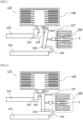
- FIG. 1 is a front view showing an open contact state of a circuit breaker equipped with an electromagnetic actuator according to Embodiment 1.
- FIG. 2 is a front view showing a close contact state of the circuit breaker equipped with the electromagnetic actuator according to Embodiment 1.
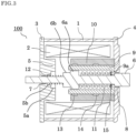
- FIG. 3 is a sectional view showing a demagnetization state of the electromagnetic actuator according to Embodiment 1.
- FIG. 4 is a sectional view showing an excitation operation completion state of the electromagnetic actuator according to Embodiment 1.
- a circuit breaker 110 according to Embodiment 1 is a circuit breaker in which, by excitation of an electromagnetic coil of an electromagnetic actuator 100, a close contact state of main contacts is maintained or the main contacts are in an open contact state.
- the circuit breaker 110 has a movable side main contact 104 and a fixed side main contact 105 which are a pair of main contacts, the electromagnetic actuator 100 provided with a shaft 6 that operates opening or closing operation of the main contacts, and an arc extinguishing chamber 108.
- a movable conductor 103, a flexible conductor 106, a lower conductor 101, and an open contact spring 107 are provided on the movable side main contact 104 side.
- An upper conductor 102 is provided on the fixed side main contact 105 side.
- the arc extinguishing chamber 108 extinguishes an arc discharge produced when the movable side main contact 104 is separated from the fixed side main contact 105 during open contact operation.
- the fixed side main contact 105 that is one of the pair of main contacts is joined to one end portion of the upper conductor 102.
- the movable side main contact 104 that is the other of the pair of main contacts is joined to one end portion of the movable conductor 103 at a position opposite to the fixed side main contact 105.
- the other end portion of the movable conductor 103 is connected to the lower conductor 101 by the flexible conductor 106.
- the movable conductor 103 is biased by the shaft 6 of the electromagnetic actuator 100 so that the movable side main contact 104 is opened from or closed to the fixed side main contact 105.
- the movable side main contact 104 and the fixed side main contact 105 are energized via the lower conductor 101 and the upper conductor 102, respectively.
- the movable conductor 103 is driven toward the upper conductor 102, and thereby the movable side main contact 104 is brought into contact with the fixed side main contact 105.
- the movable conductor 103 is driven in a direction separating from the upper conductor 102, and thereby it is dissolved that the movable side main contact 104 comes in contact with the fixed side main contact 105.
- a state where the movable side main contact 104 comes in contact with the fixed side main contact 105 is the close contact state of the main contacts shown in FIG. 2 ; and a state where the movable side main contact 104 is separated from the fixed side main contact 105 is the open contact state of the main contacts shown in FIG. 1 .
- FIG. 3 corresponds to the open contact state of the circuit breaker 110 shown in FIG. 1 and shows the position of the movable core 9 in the demagnetization state of the electromagnetic actuator 100.
- FIG. 4 corresponds to the close contact state of the circuit breaker 110 shown in FIG. 2 and shows the position where the electromagnetic actuator 100 is excited and the movable core 9 comes in contact with the fixed core 5.
- the electromagnetic actuator 100 is configured in the following way.
- An electromagnetic coil 2 is arranged on the inner circumferential side of a first yoke 1;
- a fixed side covering plate 3 is arranged on one side of the first yoke 1;
- a movable side covering plate 4 is arranged on the other side of the first yoke 1;
- a fixed core 5 is arranged on a central portion of the fixed side covering plate 3; and a shaft 6 passes through the fixed side covering plate 3, the fixed core 5, and the movable side covering plate 4.
- the shaft 6 has: a first protrusion portion 6a; and a second protrusion portion 6b which is provided consecutively to the first protrusion portion 6a and has an outer diameter smaller than the outer diameter of the first protrusion portion 6a.
- the fixed core 5 is provided with: a first concave portion 5a of the fixed core 5 in which the second protrusion portion 6b of the shaft 6 is incorporated; and a second concave portion 5b of the fixed core 5 which has an inner diameter smaller than the inner diameter of the first concave portion 5a of the fixed core 5.
- the fixed side covering plate 3 side of the shaft 6 is removably supported by a first bearing 7 and the movable side covering plate 4 side of the shaft 6 is removably supported by a second bearing 8.
- the movable core 9 is arranged face to face with the fixed core 5 on the outer circumference of the shaft 6 and is provided with a movable core protrusion portion 9a that protrudes to the circumferential surface of the shaft 6 on one side opposite to the movable side covering plate 4; a second yoke 10 is arranged on the outer circumference of the movable core 9; a contact pressure spring 11 is arranged between the movable core protrusion portion 9a of the movable core 9 and the first protrusion portion 6a of the shaft 6; and a return spring 12 is arranged between the second concave portion 5b of the fixed core 5 and the second protrusion portion 6b of the shaft 6.
- a movable core bearing 13,14 is arranged on the inner circumferential side of the second yoke 10 and makes the movable core 9 slide so as to be reciprocally movable in an axial direction.
- An air leak stop prevention plate 15 is arranged between the movable core protrusion portion 9a of the movable core 9 and the contact pressure spring 11 in the inside of the movable core 9 and suppresses air from flowing out to the outside.
- the electromagnetic coil 2 is energized and a current flows, and thereby the magnetic circuit composed of the movable core 9, the fixed core 5, the first yoke 1, the fixed side covering plate 3, the movable side covering plate 4, and the second yoke 10 is excited. Then, the movable core 9 that is removably supported by the movable core bearing 13,14 moves while sliding toward the fixed core 5.
- the shaft 6 connected via the contact pressure spring 11 also moves in the same direction and the return spring 12 arranged between the second concave portion 5b of the fixed core 5 and the second protrusion portion 6b of the shaft 6 is compressed.
- the movable conductor 103 connected to the shaft 6 is driven to the upper conductor 102 side.
- the movable side main contact 104 comes in contact with the fixed side main contact 105
- the shaft 6 stops, the movable core 9 further moves to the upper conductor 102 side to compress the contact pressure spring 11, and contact pressure force is applied to the main contacts.
- the movable core 9 comes in contact with the fixed core 5 and the movement of the movable core 9 is completed, and thereby close contact operation is also completed.
- the energization to the electromagnetic coil 2 is stopped, and thereby the magnetic circuit is demagnetized to eliminate magnetic suction force and the movable core 9 moves by trip force of the contact pressure spring 11 in a direction opposite to a direction in which the fixed core 5 is arranged.
- the contact pressure force between the contacts is released and it becomes the open contact state between the contacts.
- the shaft 6 and the movable core 9 move together by the trip force of the open contact spring 107 and the return spring 12, the movable conductor 103 is driven in a direction to separate the movable side main contact 104 from the fixed side main contact 105, and the main contacts are separated. This makes the circuit breaker 110 to the open contact state shown in FIG. 1 .
- the movable core 9 starts to move to the fixed core 5 side; and when the current flowing to the electromagnetic coil 2 is stopped from the excitation state of the electromagnetic actuator 100 shown in FIG. 4 , the movable core 9 starts to move in a direction opposite to the direction in which the fixed core 5 is arranged, more specifically, the movable core 9 moves to the movable side covering plate 4 side.
- the movable core bearing 13,14 is provided on the outer circumferential side of the movable core 9 and the air leak stop prevention plate 15 is provided in the movable core 9, and thereby the air in a movable core movement space 16 can be suppressed from flowing out to the outside. Therefore, the movable core 9 is operated while compressing the confined air and resistance force during operation can be increased; thus, operation speed can be reduced.
- the movable side main contact 104 is driven together with the movable core 9 and the shaft 6; thus, the electromagnetic actuator 100 covers an air damper effect during opening or closing operation and can relax impact force during the opening or closing operation.
- the movable core 9 is operated while compressing the confined air and the resistance force during the operation can be increased; thus, the operation speed can be reduced.
- the electromagnetic actuator 100 disclosed in the present application is driven while being connected to the movable side main contact 104 of the circuit breaker 110; thus, the electromagnetic actuator 100 covers the air damper effect during the opening or closing operation and relaxes the impact force.
- the electromagnetic actuator 100 that can relax the impact force during the opening or closing operation can be obtained by a simple configuration and a reduction in size of the circuit breaker 110 can be achieved.
- the movable core bearing 13,14 that removably supports the movable core 9 is provided on the second yoke 10, and thereby the air from between the second yoke 10 and the movable core 9 can be suppressed from flowing out.
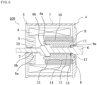
- FIG. 5 is a sectional view showing a demagnetization state of an electromagnetic actuator according to Embodiment 2.
- an air leak hole 17 is provided in a movable side covering plate 4 opposite to a movable core protrusion portion 9a of a movable core 9.
- the movable core 9 moves to a fixed core 5 side during close contact operation; and during open contact operation, the movable core 9 moves in a direction opposite to a direction in which the fixed core 5 is arranged, more specifically, the movable core 9 moves to a movable side covering plate 4 side.
- the air leak hole 17 is provided in the movable side covering plate 4; thus, the amount of air in which air in a movable core movement space 16 flows out to the outside can be adjusted by adjusting the hole diameter and the number of holes of the air leak hole 17. Consequently, resistance force during operation can be adjusted and therefore speed adjustment during opening or closing operation can be performed.
- the present application is suitable for achieving an electromagnetic actuator that can relax impact force during opening or closing operation by a simple configuration.
Landscapes
- Physics & Mathematics (AREA)
- Electromagnetism (AREA)
- Engineering & Computer Science (AREA)
- Power Engineering (AREA)
- Electromagnets (AREA)
- Driving Mechanisms And Operating Circuits Of Arc-Extinguishing High-Tension Switches (AREA)
Abstract
Description
- The present application relates to an electromagnetic actuator and a circuit breaker equipped with the electromagnetic actuator.
- In a circuit breaker equipped with an electromagnetic actuator, when a current flows in an electromagnetic coil of the electromagnetic actuator, a magnetic circuit is excited, a movable core in the electromagnetic actuator is driven in a direction toward a fixed core, and a shaft connected to the movable core moves together with the movable core, thereby performing close contact operation of contacts of the circuit breaker. (Refer to
Patent Document 1.) - Furthermore, when the flow of the current to the electromagnetic coil of the electromagnetic actuator is stopped, the magnetic circuit is demagnetized, the movable core in the electromagnetic actuator is driven in the opposite direction of the fixed core, the shaft connected to the movable core moves to the opposite side of the fixed core together with the movable core, thereby performing open contact operation of the contacts of the circuit breaker.
-
Patent Document 1JP-A-2003-318020 - In the above conventional electromagnetic actuator, there is a possibility that mechanism parts are damaged by impact force during opening or closing operation and relaxation of the impact force during the opening or closing operation is required. Shock absorption rubber material, damper parts, or the like are used for the relaxation of the impact force. Thus, for example, in the electromagnetic actuator of the circuit breaker disclosed in
Patent Document 1, the impact force during the opening or closing operation is relaxed by providing the rubber material that relaxes the impact force. - However, if the rubber material, the damper parts, or the like which relax the impact force are provided, a problem exists in that problems such as securement of an arrangement space and a change or deterioration in material characteristics due to use environment need to be considered.
- The present application has been made to solve the foregoing problem and an object thereof is to provide an electromagnetic actuator that can relax impact force during opening or closing operation by a simple configuration.
- An electromagnetic actuator disclosed in the present application includes: a first yoke in which an electromagnetic coil is arranged on an inner circumferential side; a fixed side covering plate arranged on one side of the first yoke; a movable side covering plate arranged on the other side of the first yoke; a fixed core arranged on a central portion of the fixed side covering plate; a shaft which passes through the fixed core and the movable side covering plate and has a first protrusion portion; a movable core which is arranged face to face with the fixed core on the outer circumference of the shaft and is provided with a movable core protrusion portion that protrudes to the circumferential surface of the shaft on one side opposite to the movable side covering plate; a second yoke arranged on the outer circumference of the movable core; a contact pressure spring arranged between the movable core protrusion portion of the movable core and the first protrusion portion of the shaft; a movable core bearing which is arranged on the second yoke and makes the movable core slide in an axial direction; and an air leak stop prevention plate arranged between the movable core protrusion portion of the movable core and the contact pressure spring.
- According to the electromagnetic actuator disclosed in the present application, the movable core bearing that makes the movable core slide in the axial direction is arranged on the second yoke and the air leak stop prevention plate is arranged between the movable core protrusion portion of the movable core and the contact pressure spring, whereby there can be obtained an electromagnetic actuator that can relax impact force during opening or closing operation by a simple configuration.
-
-
FIG. 1 is a front view showing an open contact state of a circuit breaker equipped with an electromagnetic actuator according toEmbodiment 1; -
FIG. 2 is a front view showing a close contact state of the circuit breaker equipped with the electromagnetic actuator according toEmbodiment 1; -
FIG. 3 is a sectional view showing a demagnetization state of the electromagnetic actuator according toEmbodiment 1; -
FIG. 4 is a sectional view showing an excitation operation completion state of the electromagnetic actuator according toEmbodiment 1; and -
FIG. 5 is a sectional view showing a demagnetization state of an electromagnetic actuator according toEmbodiment 2. - Hereinafter,
Embodiment 1 will be described on the basis ofFIG. 1 to FIG. 4 ; and, in each of the drawings, identical or equivalent members and portions will be described with the same reference numerals (and letters) assigned thereto.FIG. 1 is a front view showing an open contact state of a circuit breaker equipped with an electromagnetic actuator according toEmbodiment 1.FIG. 2 is a front view showing a close contact state of the circuit breaker equipped with the electromagnetic actuator according toEmbodiment 1.FIG. 3 is a sectional view showing a demagnetization state of the electromagnetic actuator according toEmbodiment 1.FIG. 4 is a sectional view showing an excitation operation completion state of the electromagnetic actuator according toEmbodiment 1. - A
circuit breaker 110 according toEmbodiment 1 is a circuit breaker in which, by excitation of an electromagnetic coil of anelectromagnetic actuator 100, a close contact state of main contacts is maintained or the main contacts are in an open contact state. As shown inFIG. 1 and FIG. 2 , thecircuit breaker 110 has a movable sidemain contact 104 and a fixed sidemain contact 105 which are a pair of main contacts, theelectromagnetic actuator 100 provided with ashaft 6 that operates opening or closing operation of the main contacts, and anarc extinguishing chamber 108. - A
movable conductor 103, aflexible conductor 106, alower conductor 101, and anopen contact spring 107 are provided on the movable sidemain contact 104 side. Anupper conductor 102 is provided on the fixed sidemain contact 105 side. Thearc extinguishing chamber 108 extinguishes an arc discharge produced when the movable sidemain contact 104 is separated from the fixed sidemain contact 105 during open contact operation. - The fixed side
main contact 105 that is one of the pair of main contacts is joined to one end portion of theupper conductor 102. The movable sidemain contact 104 that is the other of the pair of main contacts is joined to one end portion of themovable conductor 103 at a position opposite to the fixed sidemain contact 105. The other end portion of themovable conductor 103 is connected to thelower conductor 101 by theflexible conductor 106. Themovable conductor 103 is biased by theshaft 6 of theelectromagnetic actuator 100 so that the movable sidemain contact 104 is opened from or closed to the fixed sidemain contact 105. - The movable side
main contact 104 and the fixed sidemain contact 105 are energized via thelower conductor 101 and theupper conductor 102, respectively. Themovable conductor 103 is driven toward theupper conductor 102, and thereby the movable sidemain contact 104 is brought into contact with the fixed sidemain contact 105. Furthermore, themovable conductor 103 is driven in a direction separating from theupper conductor 102, and thereby it is dissolved that the movable sidemain contact 104 comes in contact with the fixed sidemain contact 105. - A state where the movable side
main contact 104 comes in contact with the fixed sidemain contact 105 is the close contact state of the main contacts shown inFIG. 2 ; and a state where the movable sidemain contact 104 is separated from the fixed sidemain contact 105 is the open contact state of the main contacts shown inFIG. 1 . - Next, description will be made on the configuration of the
electromagnetic actuator 100.FIG. 3 corresponds to the open contact state of thecircuit breaker 110 shown inFIG. 1 and shows the position of themovable core 9 in the demagnetization state of theelectromagnetic actuator 100.FIG. 4 corresponds to the close contact state of thecircuit breaker 110 shown inFIG. 2 and shows the position where theelectromagnetic actuator 100 is excited and themovable core 9 comes in contact with thefixed core 5. - The
electromagnetic actuator 100 is configured in the following way. Anelectromagnetic coil 2 is arranged on the inner circumferential side of afirst yoke 1; a fixedside covering plate 3 is arranged on one side of thefirst yoke 1; a movableside covering plate 4 is arranged on the other side of thefirst yoke 1; afixed core 5 is arranged on a central portion of the fixedside covering plate 3; and ashaft 6 passes through the fixedside covering plate 3, thefixed core 5, and the movableside covering plate 4. - The
shaft 6 has: afirst protrusion portion 6a; and asecond protrusion portion 6b which is provided consecutively to thefirst protrusion portion 6a and has an outer diameter smaller than the outer diameter of thefirst protrusion portion 6a. Thefixed core 5 is provided with: a firstconcave portion 5a of thefixed core 5 in which thesecond protrusion portion 6b of theshaft 6 is incorporated; and a secondconcave portion 5b of thefixed core 5 which has an inner diameter smaller than the inner diameter of the firstconcave portion 5a of thefixed core 5. - The fixed
side covering plate 3 side of theshaft 6 is removably supported by a first bearing 7 and the movableside covering plate 4 side of theshaft 6 is removably supported by a second bearing 8. Themovable core 9 is arranged face to face with the fixedcore 5 on the outer circumference of theshaft 6 and is provided with a movablecore protrusion portion 9a that protrudes to the circumferential surface of theshaft 6 on one side opposite to the movableside covering plate 4; asecond yoke 10 is arranged on the outer circumference of themovable core 9; acontact pressure spring 11 is arranged between the movablecore protrusion portion 9a of themovable core 9 and thefirst protrusion portion 6a of theshaft 6; and areturn spring 12 is arranged between the secondconcave portion 5b of the fixedcore 5 and thesecond protrusion portion 6b of theshaft 6. - A movable core bearing 13,14 is arranged on the inner circumferential side of the
second yoke 10 and makes themovable core 9 slide so as to be reciprocally movable in an axial direction. An air leakstop prevention plate 15 is arranged between the movablecore protrusion portion 9a of themovable core 9 and thecontact pressure spring 11 in the inside of themovable core 9 and suppresses air from flowing out to the outside. - Next, description will be made on the operation of the
electromagnetic actuator 100. First, theelectromagnetic coil 2 is energized and a current flows, and thereby the magnetic circuit composed of themovable core 9, thefixed core 5, thefirst yoke 1, the fixedside covering plate 3, the movableside covering plate 4, and thesecond yoke 10 is excited. Then, themovable core 9 that is removably supported by the movable core bearing 13,14 moves while sliding toward the fixedcore 5. - At this point, the
shaft 6 connected via thecontact pressure spring 11 also moves in the same direction and thereturn spring 12 arranged between the secondconcave portion 5b of the fixedcore 5 and thesecond protrusion portion 6b of theshaft 6 is compressed. Themovable conductor 103 connected to theshaft 6 is driven to theupper conductor 102 side. When the movable sidemain contact 104 comes in contact with the fixed sidemain contact 105, theshaft 6 stops, themovable core 9 further moves to theupper conductor 102 side to compress thecontact pressure spring 11, and contact pressure force is applied to the main contacts. After that, themovable core 9 comes in contact with the fixedcore 5 and the movement of themovable core 9 is completed, and thereby close contact operation is also completed. - Furthermore, the energization to the
electromagnetic coil 2 is stopped, and thereby the magnetic circuit is demagnetized to eliminate magnetic suction force and themovable core 9 moves by trip force of thecontact pressure spring 11 in a direction opposite to a direction in which the fixedcore 5 is arranged. At this point, the contact pressure force between the contacts is released and it becomes the open contact state between the contacts. Theshaft 6 and themovable core 9 move together by the trip force of theopen contact spring 107 and thereturn spring 12, themovable conductor 103 is driven in a direction to separate the movable sidemain contact 104 from the fixed sidemain contact 105, and the main contacts are separated. This makes thecircuit breaker 110 to the open contact state shown inFIG. 1 . - Next, description will be made on the relationship of arrangement of the
movable core bearing stop prevention plate 15 in theelectromagnetic actuator 100 according toEmbodiment 1. - As described above, when the
electromagnetic coil 2 is energized and a current flows from the demagnetization state of theelectromagnetic actuator 100 shown inFIG. 3 , themovable core 9 starts to move to the fixedcore 5 side; and when the current flowing to theelectromagnetic coil 2 is stopped from the excitation state of theelectromagnetic actuator 100 shown inFIG. 4 , themovable core 9 starts to move in a direction opposite to the direction in which the fixedcore 5 is arranged, more specifically, themovable core 9 moves to the movableside covering plate 4 side. - At this point, the
movable core bearing movable core 9 and the air leakstop prevention plate 15 is provided in themovable core 9, and thereby the air in a movablecore movement space 16 can be suppressed from flowing out to the outside. Therefore, themovable core 9 is operated while compressing the confined air and resistance force during operation can be increased; thus, operation speed can be reduced. - As described above, the movable side
main contact 104 is driven together with themovable core 9 and theshaft 6; thus, theelectromagnetic actuator 100 covers an air damper effect during opening or closing operation and can relax impact force during the opening or closing operation. - The
movable core 9 is operated while compressing the confined air and the resistance force during the operation can be increased; thus, the operation speed can be reduced. Theelectromagnetic actuator 100 disclosed in the present application is driven while being connected to the movable sidemain contact 104 of thecircuit breaker 110; thus, theelectromagnetic actuator 100 covers the air damper effect during the opening or closing operation and relaxes the impact force. - As described above, rubber material, damper parts, or the like which relax impact force do not need to be provided; thus, the
electromagnetic actuator 100 that can relax the impact force during the opening or closing operation can be obtained by a simple configuration and a reduction in size of thecircuit breaker 110 can be achieved. - Furthermore, the
movable core bearing movable core 9 is provided on thesecond yoke 10, and thereby the air from between thesecond yoke 10 and themovable core 9 can be suppressed from flowing out. -
Embodiment 2 will be described on the basis ofFIG. 5 ; and, in the drawing, identical or equivalent members will be described with the same reference numerals (and letters) assigned thereto.FIG. 5 is a sectional view showing a demagnetization state of an electromagnetic actuator according toEmbodiment 2. - Hereinafter, referring to
FIG. 5 , description will be made on the configuration of anelectromagnetic actuator 100 according toEmbodiment 2. InFIG. 5 , anair leak hole 17 is provided in a movableside covering plate 4 opposite to a movablecore protrusion portion 9a of amovable core 9. - The
movable core 9 moves to a fixedcore 5 side during close contact operation; and during open contact operation, themovable core 9 moves in a direction opposite to a direction in which the fixedcore 5 is arranged, more specifically, themovable core 9 moves to a movableside covering plate 4 side. However, as shown inFIG. 5 , theair leak hole 17 is provided in the movableside covering plate 4; thus, the amount of air in which air in a movablecore movement space 16 flows out to the outside can be adjusted by adjusting the hole diameter and the number of holes of theair leak hole 17. Consequently, resistance force during operation can be adjusted and therefore speed adjustment during opening or closing operation can be performed. - The present application describes various exemplified embodiments and examples; however, various features, aspects, and functions described in one or a plurality of embodiments are not limited to specific embodiments, but are applicable to embodiments individually or in various combinations thereof. Therefore, countless modified examples not exemplified are assumed in technical ranges disclosed in the specification of the present application. For example, there include: a case in which at least one constituent element is modified; a case, added; or a case, omitted; and a case in which at least one constituent element is extracted to combine with constituent elements of other embodiments.
- The present application is suitable for achieving an electromagnetic actuator that can relax impact force during opening or closing operation by a simple configuration.
- 1 First yoke, 2 Electromagnetic coil, 3 Fixed side covering plate, 4 Movable side covering plate, 5 Fixed core, 5a First concave portion, 5b Second concave portion, 6 Shaft, 6a First protrusion portion, 6b Second protrusion portion, 9 Movable core, 9a Movable core protrusion portion, 10 Second yoke, 11 Contact pressure spring, 12 Return spring, 13 Movable core bearing, 14 Movable core bearing, 15 Air leak stop prevention plate, 16 Movable core movement space, 17 Air leak hole, 100 Electromagnetic actuator, 110 Circuit breaker
Claims (4)
- An electromagnetic actuator comprising:a first yoke in which an electromagnetic coil is arranged on an inner circumferential side;a fixed side covering plate arranged on one side of the first yoke;a movable side covering plate arranged on the other side of the first yoke;a fixed core arranged on a central portion of the fixed side covering plate;a shaft which passes through the fixed core and the movable side covering plate and has a first protrusion portion;a movable core which is arranged face to face with the fixed core on the outer circumference of the shaft and is provided with a movable core protrusion portion that protrudes to the circumferential surface of the shaft on one side opposite to the movable side covering plate;a second yoke arranged on the outer circumference of the movable core;a contact pressure spring arranged between the movable core protrusion portion of the movable core and the first protrusion portion of the shaft;a movable core bearing which is arranged on the second yoke and makes the movable core slide in an axial direction; andan air leak stop prevention plate arranged between the movable core protrusion portion of the movable core and the contact pressure spring.
- The electromagnetic actuator according to claim 1,
further comprising an air leak hole provided in the movable side covering plate opposite to the movable core protrusion portion of the movable core. - The electromagnetic actuator according to claim 1 or claim 2,further comprising: a second protrusion portion of the shaft which is provided consecutively to the first protrusion portion of the shaft and has an outer diameter smaller than the first protrusion portion;a first concave portion of the fixed core in which the second protrusion portion of the shaft is incorporated;a second concave portion of the fixed core which has an inner diameter smaller than the first concave portion of the fixed core; anda return spring arranged between the second concave portion of the fixed core and the second protrusion portion of the shaft.
- A circuit breaker equipped with an electromagnetic actuator as set forth in any one of claim 1 to claim 3.
Applications Claiming Priority (1)
| Application Number | Priority Date | Filing Date | Title |
|---|---|---|---|
| PCT/JP2020/043730 WO2022113182A1 (en) | 2020-11-25 | 2020-11-25 | Electromagnetic actuator and electromagnetic actuator-equipped circuit breaker |
Publications (2)
| Publication Number | Publication Date |
|---|---|
| EP4254459A1 true EP4254459A1 (en) | 2023-10-04 |
| EP4254459A4 EP4254459A4 (en) | 2023-12-20 |
Family
ID=81754113
Family Applications (1)
| Application Number | Title | Priority Date | Filing Date |
|---|---|---|---|
| EP20963447.6A Pending EP4254459A4 (en) | 2020-11-25 | 2020-11-25 | Electromagnetic actuator and electromagnetic actuator-equipped circuit breaker |
Country Status (3)
| Country | Link |
|---|---|
| EP (1) | EP4254459A4 (en) |
| JP (1) | JP7366292B2 (en) |
| WO (1) | WO2022113182A1 (en) |
Family Cites Families (12)
| Publication number | Priority date | Publication date | Assignee | Title |
|---|---|---|---|---|
| JPS55146911A (en) * | 1980-04-04 | 1980-11-15 | Tokai Rika Co Ltd | Time-limit solenoid |
| JPS59164217U (en) * | 1983-04-19 | 1984-11-02 | アルプス電気株式会社 | solenoid |
| JPS59228701A (en) * | 1983-06-10 | 1984-12-22 | Tokyo Electric Co Ltd | Electromagnet |
| JPS6011416U (en) * | 1983-06-30 | 1985-01-25 | 松下電工株式会社 | silence solenoid |
| JPH01173911U (en) * | 1988-05-26 | 1989-12-11 | ||
| US5663700A (en) * | 1995-08-25 | 1997-09-02 | Trombetta Corporation | Sound dampening solenoid |
| JP2001143927A (en) * | 1999-11-16 | 2001-05-25 | Aichi Electric Co Ltd | Device for reducing noise of solenoid |
| JP3713576B2 (en) * | 2002-04-25 | 2005-11-09 | ティディエス株式会社 | solenoid |
| DE102013225392A1 (en) * | 2013-12-10 | 2015-06-11 | Robert Bosch Gmbh | Electromagnet of an electromagnetically actuated fluid valve |
| DE102015213840B4 (en) * | 2015-07-22 | 2025-04-03 | Robert Bosch Gmbh | Normally closed solenoid valve |
| ES1144259Y (en) * | 2015-08-27 | 2015-12-29 | Bitron Ind Espana Sa | ELECTROIMAN BI-STABLE PROVIDED WITH A NOISE SHOCK ABSORBER SYSTEM AND MAGNETIC COMPENSATOR |
| JP6768174B1 (en) * | 2019-11-14 | 2020-10-14 | 三菱電機株式会社 | Electromagnetic actuator |
-
2020
- 2020-11-25 EP EP20963447.6A patent/EP4254459A4/en active Pending
- 2020-11-25 JP JP2022564863A patent/JP7366292B2/en active Active
- 2020-11-25 WO PCT/JP2020/043730 patent/WO2022113182A1/en not_active Ceased
Also Published As
| Publication number | Publication date |
|---|---|
| WO2022113182A1 (en) | 2022-06-02 |
| JP7366292B2 (en) | 2023-10-20 |
| EP4254459A4 (en) | 2023-12-20 |
| JPWO2022113182A1 (en) | 2022-06-02 |
Similar Documents
| Publication | Publication Date | Title |
|---|---|---|
| CN103650089B (en) | Electromagnetic operating device and employ the opening and closing device of this device | |
| EP1939909A3 (en) | Circuit breaker and opening and closing method thereof | |
| US8915482B2 (en) | Solenoid with an armature | |
| EP3761337A1 (en) | Electromagnetic actuator, switch, and switch gear | |
| CN103443894A (en) | Gas Insulated High Voltage Power Switches | |
| EP3089188B1 (en) | Opening and closing device | |
| KR102917609B1 (en) | Relay | |
| KR102917594B1 (en) | Relay | |
| EP4254459A1 (en) | Electromagnetic actuator and electromagnetic actuator-equipped circuit breaker | |
| KR102917597B1 (en) | Relay | |
| CN101728052B (en) | Release electromagnet device | |
| HK40096953A (en) | Electromagnetic actuator and electromagnetic actuator-equipped circuit breaker | |
| KR20240151649A (en) | Relay | |
| KR20240151657A (en) | Relay | |
| US10431396B2 (en) | Charging ram assembly, and pin assembly and securing method therefor | |
| KR101284133B1 (en) | Electro magnetic force driving device with line test | |
| KR102888015B1 (en) | Relay | |
| KR102917604B1 (en) | Relay | |
| JP7412600B2 (en) | Overcurrent trip device and circuit breaker using the same | |
| CN218975361U (en) | Relay device | |
| US10825631B2 (en) | Solenoid assembly with decreased release time | |
| JP2013115014A (en) | Gas breaker | |
| EP4411780A1 (en) | Device for limiting movement of movable part in electrical equipment | |
| US12494333B2 (en) | Fault breaking contactor with dynamic air gap mechanism | |
| JP7361889B2 (en) | Electromagnetic actuator and circuit breaker using this electromagnetic actuator |
Legal Events
| Date | Code | Title | Description |
|---|---|---|---|
| STAA | Information on the status of an ep patent application or granted ep patent |
Free format text: STATUS: THE INTERNATIONAL PUBLICATION HAS BEEN MADE |
|
| PUAI | Public reference made under article 153(3) epc to a published international application that has entered the european phase |
Free format text: ORIGINAL CODE: 0009012 |
|
| STAA | Information on the status of an ep patent application or granted ep patent |
Free format text: STATUS: REQUEST FOR EXAMINATION WAS MADE |
|
| 17P | Request for examination filed |
Effective date: 20221202 |
|
| AK | Designated contracting states |
Kind code of ref document: A1 Designated state(s): AL AT BE BG CH CY CZ DE DK EE ES FI FR GB GR HR HU IE IS IT LI LT LU LV MC MK MT NL NO PL PT RO RS SE SI SK SM TR |
|
| A4 | Supplementary search report drawn up and despatched |
Effective date: 20231122 |
|
| RIC1 | Information provided on ipc code assigned before grant |
Ipc: H01F 7/08 20060101ALI20231116BHEP Ipc: H01F 7/16 20060101ALI20231116BHEP Ipc: H01H 33/38 20060101AFI20231116BHEP |
|
| DAV | Request for validation of the european patent (deleted) | ||
| DAX | Request for extension of the european patent (deleted) | ||
| REG | Reference to a national code |
Ref country code: HK Ref legal event code: DE Ref document number: 40096953 Country of ref document: HK |
|
| STAA | Information on the status of an ep patent application or granted ep patent |
Free format text: STATUS: EXAMINATION IS IN PROGRESS |
|
| 17Q | First examination report despatched |
Effective date: 20250709 |