EP4254398A2 - Electronic cymbal and striking detection method - Google Patents
Electronic cymbal and striking detection method Download PDFInfo
- Publication number
- EP4254398A2 EP4254398A2 EP22188436.4A EP22188436A EP4254398A2 EP 4254398 A2 EP4254398 A2 EP 4254398A2 EP 22188436 A EP22188436 A EP 22188436A EP 4254398 A2 EP4254398 A2 EP 4254398A2
- Authority
- EP
- European Patent Office
- Prior art keywords
- frame
- cover part
- sensor
- upper cover
- peripheral side
- Prior art date
- Legal status (The legal status is an assumption and is not a legal conclusion. Google has not performed a legal analysis and makes no representation as to the accuracy of the status listed.)
- Granted
Links
Images


Classifications
-
- G—PHYSICS
- G01—MEASURING; TESTING
- G01M—TESTING STATIC OR DYNAMIC BALANCE OF MACHINES OR STRUCTURES; TESTING OF STRUCTURES OR APPARATUS, NOT OTHERWISE PROVIDED FOR
- G01M7/00—Vibration-testing of structures; Shock-testing of structures
- G01M7/08—Shock-testing
-
- G—PHYSICS
- G10—MUSICAL INSTRUMENTS; ACOUSTICS
- G10H—ELECTROPHONIC MUSICAL INSTRUMENTS; INSTRUMENTS IN WHICH THE TONES ARE GENERATED BY ELECTROMECHANICAL MEANS OR ELECTRONIC GENERATORS, OR IN WHICH THE TONES ARE SYNTHESISED FROM A DATA STORE
- G10H3/00—Instruments in which the tones are generated by electromechanical means
- G10H3/12—Instruments in which the tones are generated by electromechanical means using mechanical resonant generators, e.g. strings or percussive instruments, the tones of which are picked up by electromechanical transducers, the electrical signals being further manipulated or amplified and subsequently converted to sound by a loudspeaker or equivalent instrument
- G10H3/14—Instruments in which the tones are generated by electromechanical means using mechanical resonant generators, e.g. strings or percussive instruments, the tones of which are picked up by electromechanical transducers, the electrical signals being further manipulated or amplified and subsequently converted to sound by a loudspeaker or equivalent instrument using mechanically actuated vibrators with pick-up means
- G10H3/146—Instruments in which the tones are generated by electromechanical means using mechanical resonant generators, e.g. strings or percussive instruments, the tones of which are picked up by electromechanical transducers, the electrical signals being further manipulated or amplified and subsequently converted to sound by a loudspeaker or equivalent instrument using mechanically actuated vibrators with pick-up means using a membrane, e.g. a drum; Pick-up means for vibrating surfaces, e.g. housing of an instrument
-
- G—PHYSICS
- G10—MUSICAL INSTRUMENTS; ACOUSTICS
- G10H—ELECTROPHONIC MUSICAL INSTRUMENTS; INSTRUMENTS IN WHICH THE TONES ARE GENERATED BY ELECTROMECHANICAL MEANS OR ELECTRONIC GENERATORS, OR IN WHICH THE TONES ARE SYNTHESISED FROM A DATA STORE
- G10H1/00—Details of electrophonic musical instruments
- G10H1/32—Constructional details
-
- G—PHYSICS
- G10—MUSICAL INSTRUMENTS; ACOUSTICS
- G10H—ELECTROPHONIC MUSICAL INSTRUMENTS; INSTRUMENTS IN WHICH THE TONES ARE GENERATED BY ELECTROMECHANICAL MEANS OR ELECTRONIC GENERATORS, OR IN WHICH THE TONES ARE SYNTHESISED FROM A DATA STORE
- G10H2230/00—General physical, ergonomic or hardware implementation of electrophonic musical tools or instruments, e.g. shape or architecture
- G10H2230/045—Special instrument [spint], i.e. mimicking the ergonomy, shape, sound or other characteristic of a specific acoustic musical instrument category
- G10H2230/251—Spint percussion, i.e. mimicking percussion instruments; Electrophonic musical instruments with percussion instrument features; Electrophonic aspects of acoustic percussion instruments or MIDI-like control therefor
- G10H2230/321—Spint cymbal, i.e. mimicking thin center-held gong-like instruments made of copper-based alloys, e.g. ride cymbal, china cymbal, sizzle cymbal, swish cymbal, zill, i.e. finger cymbals
Definitions
- the invention relates to an electronic cymbal and a striking detection method, and particularly relates to an electronic cymbal and a striking detection method capable of facilitating the sensor sensitivity with respect to striking from a lateral direction.
- An electronic cymbal including a frame, an edge sensor installed to an upper surface on an outer edge side of the frame, and a cover covering an upper surface of the frame in a state in which a space is formed between the edge sensor and the cover and detecting striking to an outer edge portion of the cover (frame) by the edge sensor is known.
- Patent Document 1 recites an electronic cymbal including an upper cover part 5b1 covering an upper surface of a frame 4 and a lower cover part 5b2 with coverage from an outer edge (outer peripheral surface) of the frame 4 to an edge part of a lower surface.
- a protrusion part 5b3 protruding toward an edge sensor 7b is formed in the upper cover part 5b1, and when the performer strikes an outer edge portion of the upper cover part 5b1 from the top by a stick, etc., due to elastic deformation (bending) of the upper cover part 5b1, the protrusion part 5b3 is pressed to the edge sensor 7b. Accordingly, the striking to the outer edge portion of the cover 5 (the frame 4) is detected by the edge sensor 7b.
- Patent Document 1 Japanese Laid-open No. 2021-026077 (e.g., para. 0040, 0041, FIG. 4 )
- the invention has been made to solve the above issue, and an objective of the invention is to provide an electronic cymbal and a striking detection method capable of facilitating the sensor sensitivity with respect to the striking from the lateral direction.
- an electronic cymbal includes: a plate-like frame; a sensor installed to an upper surface on an outer edge side of the frame; and a cover covering upper surfaces of the sensor and the frame.
- the cover includes an upper cover part covering the upper surface of the frame in a state in which a space is formed between the upper cover part and the sensor; a lateral cover part extending from an outer edge of the upper cover part and covering an outer peripheral surface of the frame in a state in which a space is formed between the lateral cover part and an outer peripheral surface of the frame; and a lower cover part, extending from a lower end of the lateral cover part to an inner peripheral side and covering a lower surface of the frame.
- the upper cover part or the frame comprises a stopper facing the space between the upper cover part and the sensor and limits deformation of the upper cover part toward an inner peripheral side.
- An electronic cymbal includes: a plate-like frame; a sensor installed to an upper surface on an outer edge side of the frame; and a cover covering upper surfaces of the sensor and the frame.
- the cover includes an upper cover part covering the upper surface of the frame in a state in which a space is formed between the upper cover part and the sensor; a lateral cover part extending from an outer edge of the upper cover part and covering an outer peripheral surface of the frame in a state in which a space is formed between the lateral cover part and an outer peripheral surface of the frame; and a lower cover part, extending from a lower end of the lateral cover part to an inner peripheral side and covering a lower surface of the frame.
- the frame includes: a covered part covered in a state of being contacted by the upper cover part; and a sensor installation part which is located on an outer peripheral side with respect to the covered part and to which the sensor is installed.
- the upper cover part includes a protrusion which protrudes toward the sensor and in which a lower surface is parallel to an upper surface of the sensor installation part.
- the upper surface of the sensor installation part tilts downward toward an outer peripheral side at a slope greater than that of an upper surface of the covered part, and an interval between the upper surface of the sensor installation part and the lower surface of the upper cover part is formed to gradually increase from an inner peripheral side toward the outer peripheral side.
- the electronic cymbal includes: a plate-like frame; a sensor installed to an upper surface on an outer edge side of the frame; and a cover covering upper surfaces of the sensor and the frame.
- the cover includes: an upper cover part covering the upper surface of the frame in a state in which a space is formed between the upper cover part and the sensor; a lateral cover part extending from an outer edge of the upper cover part and covering an outer peripheral surface of the frame in a state in which a space is formed between the lateral cover part and an outer peripheral surface of the frame; and a lower cover part, extending from a lower end of the lateral cover part to an inner peripheral side and covering a lower surface of the frame.
- the upper cover part or the frame includes a stopper facing the space between the upper cover part and the sensor.
- the striking detection method includes: at the time of striking an outer edge of the cover, limiting deformation of the upper cover part toward an inner peripheral side by the stopper and detecting striking to the cover by pressing the sensor by the upper cover part deformed with the stopper as a fulcrum.
- the electronic cymbal includes: a plate-like frame; a sensor installed to an upper surface on an outer edge side of the frame; and a cover covering upper surfaces of the sensor and the frame.
- the cover includes: an upper cover part covering the upper surface of the frame in a state in which a space is formed between the upper cover part and the sensor; a lateral cover part extending from an outer edge of the upper cover part and covering an outer peripheral surface of the frame in a state in which a space is formed between the lateral cover part and an outer peripheral surface of the frame; and a lower cover part, extending from a lower end of the lateral cover part to an inner peripheral side and covering a lower surface of the frame.
- the frame includes: a covered part covered in a state of being contacted by the upper cover part; and a sensor installation part which is located on an outer peripheral side with respect to the covered part and to which the sensor is installed.
- the upper cover part includes a protrusion which protrudes toward the sensor and in which a lower surface is parallel to an upper surface of the sensor installation part.
- the upper surface of the sensor installation part tilts downward toward an outer peripheral side at a slope greater than that of an upper surface of the covered part, and an interval between the upper surface of the sensor installation part and the lower surface of the upper cover part is formed to gradually increase toward the outer peripheral side.
- the striking detection method includes: at the time of striking the outside of the cover, suppressing the upper cover part and the lateral cover part from contacting an outer edge of the sensor installation part, and detecting striking to the cover by pressing the sensor by the protrusion displaced together with deformation of the upper cover part.
- FIG. 1 is a cross-sectional view illustrating an electronic cymbal 1 according to a first embodiment.
- FIG. 1 illustrates an end surface cut at a plane along a central axis of a frame 2 that is disc-shaped (the same applies to FIG. 2 and subsequent drawings).
- the description is made by setting the direction along the central axis of the disc-shaped frame 2 as upper-lower direction and a direction (radial direction) orthogonal to the upper-lower direction as a left-right direction.
- the electronic cymbal 1 is an electronic percussion instrument that simulates an acoustic cymbal (referred to as "cymbal" in the following).
- the skeleton of the electronic cymbal 1 is formed by the frame 2.
- the frame 2 is a frame made of resin and including a bell frame 20 that simulates the shape of a bell of the cymbal and a bow frame 21 that simulates the shape of a bow of the cymbal.
- the bell frame 20 is formed in a bowl shape tilting downward from the central side thereof toward the outer peripheral side, and the bow frame 21 extends from the outer edge of the bell frame 20 toward the outer peripheral side (the outer side in the left-right direction).
- the bow frame 21 gradually tilts downward with respect to the bell frame 20 toward the outer peripheral side, and the frame 2 as a whole is formed in a substantially disc shape by integrally forming the bell frame 20 and the bow frame 21.
- a through hole 22 is formed at the center of the bell frame 20, and an inner wall part 30 of a case 3 is caught to the through hole 22.
- the inner wall part 30 is formed in a substantially cylindrical shape, and the inner peripheral side of the inner wall part 30 (the inner side in the left-right direction) is blocked by a disc-shaped support part 32 having a through hole 31 at the center.
- a rod (not shown) for supporting the electronic cymbal 1 is inserted into the through hole 31 of the support part 32.
- a bottom wall part 33 extends from the lower end of the inner wall part 30 toward the outer peripheral side. By fixing the outer edge of the bottom wall part 33 to the lower surface of the frame 2 (the bow frame 21), a space surrounded by the frame 2 and the case 3 is formed on the lower surface side of the frame 2.
- the striking sensor is a piezoelectric element detecting the vibration of the frame 2.
- each of the bell frame 20 and the bow frame 21 is covered by a cover 4 made of rubber and having a through hole 40 at the center, and the cover 4 is formed in a shape (substantially disc shape) along each of the frames 20 and 21.
- a bell part sensor not shown herein is provided between the cover 4 and the bell frame 20, and the bell part sensor is a pressure sensor (e.g., a membrane switch) that is sheet-like and is ON/OFF when the cover 4 covering the bell frame 20 is struck.
- the striking to the bell frame 20 is detected by the bell part sensor, and the striking to the bow frame 21 is detected by the striking sensor.
- the striking to the edge (outer edge) portion of the bow frame 21 is detected by an edge sensor 5.
- the striking detected by each sensor is converted into an electrical signal and output to a sound source device not shown herein. Accordingly, a musical sound in accordance with a striking position to the electronic cymbal 1 is generated.
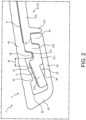
- FIG. 2 is a partially enlarged cross-sectional view of the electronic cymbal 1 in which a portion II of FIG. 1 is enlarged.
- FIG. 3 (a) is a partially enlarged cross-sectional view of the electronic cymbal 1 illustrating a state in which an edge portion is struck by normal striking, and (b) is a partially enlarged cross-sectional view of the electronic cymbal 1 illustrating a state in which the edge portion is struck by striking from a lateral direction.
- FIG. 2 and (a) and (b) of FIG. 3 in order to simplify the drawings, the hatching of the frame 2 (the bow frame 21) and the cover 4 is omitted.
- each configuration of the electronic cymbal 1 described in the following is formed to be continuous in the peripheral direction. However, a portion of the configuration may also be intermittent in the peripheral direction.
- the cover 4 includes the upper cover part 41 covering the upper surface side of the bow frame 21, a lateral cover part 42 extending downward from the outer edge (the end part on the left side of FIG. 2 ) of the upper cover part 41, a lower cover part 43 extending from the lower end of the lateral cover part 42 toward the inner peripheral side (the right side of FIG. 2 ), and a bonding part 44 bent upward from the inner edge of the lower cover part 43.
- the parts 41 to 44 are integrally formed.
- the upper cover part 41 is bonded to the upper surface of the bow frame 21 by a double-side tape 6, and the upper surface of the bonding part 44 is bonded to the lower surface of the bow frame 21 by an adhesive. Meanwhile, on the outer peripheral side with respect to these bonded portions, neither of the upper cover part 41, the lateral cover part 42, and the lower cover part 43 is bonded to the bow frame 21.
- a portion bonded to the upper cover part 41 i.e., a portion covered in a state of being contacted by the upper cover part 41 is described as a covered part 21a.
- a bent part 21b is bent downward from the outer edge of the covered part 21a, an overhang part 21c overhangs from the lower end of the bent part 21b toward the outer peripheral side.
- a sensor installation part 21d extends from the upper end on the outer edge side of the overhang part 21c to the outer peripheral side.
- the edge sensor 5 is bonded to the upper surface of the sensor installation part 21d, and the edge sensor 5 is also a sheet-like pressure sensor (e.g., a membrane switch) like the bell part sensor.
- the upper cover part 41 covers the bow frame 21 in a state in which a space S1 is formed between the upper cover part 41 and the edge sensor 5 (the sensor installation part 21d).
- a protrusion 45 protruding toward the edge sensor 5 (downward) is integrally formed on the lower surface of the upper cover part 41.
- the protrusion 45 is a portion pressing the edge sensor 5 at the time when the outer edge portion of the upper cover part 41 is struck.
- a stopper 46 integrally formed with the upper cover part 41 is provided on the inner peripheral side with respect to the protrusion 45.
- the stopper 46 is a protrusion protruding downward from the upper cover part 41 and inserted into a recess part 21e formed on the upper surface of the bow frame 21.
- the recess part 21e is a groove formed by the bent part 21b, the overhang part 21c, and the sensor installation part 21d of the bow frame 21.
- pre-striking state In a state before the upper cover part 41 is struck (referred to as "pre-striking state” in the following), the stopper 46 and the bottom surface of the recess part 21e are in contact with each other or slightly separated (less than a gap between the protrusion 45 and the edge sensor 5).
- the lateral cover part 42 and the lower cover part 43 deform downward so as to be separated from the bow frame 21 (the overhang part 21c and the sensor installation part 21d). This is because, as described above, the lateral cover part 42 and the lower cover part 43 are not bonded to the bow frame 21 on the outer peripheral side with respect to the bonding part 44.
- the stopper 46 faces the space S1, and there is no rubber filling the space S1 on the outer peripheral side of the stopper 46. Therefore, the upper cover part 41 is easily deformed to bend with the root portion of the stopper 46 as the start point. Accordingly, for example, even in the case where the outer edge portion of the upper cover part 41 is struck lightly from the lateral direction (see (b) of FIG. 3 ), the protrusion 45 is easily pressed to the edge sensor 5. Accordingly, the sensitivity of the edge sensor 5 with respect to the striking from the lateral direction can be facilitated.
- the force applied to the bonding portion (the double-side tape 6) between the covered part 21a and the upper cover part 41 can be reduced. Accordingly, the upper cover part 41 can be prevented from being peeled off from the covered part 21a.
- a bonding position P1 between the bonding part 44 and the lower surface of the bow frame 21 is located on the inner peripheral side with respect to the stopper 46, and neither of the lateral cover part 42 and the lower cover part 43 is bonded to the bow frame 21 on the outer peripheral side with respect to the bonding position P1. Accordingly, in both (referred to as "striking from the respective directions" in the following) of the normal striking (see (a) of FIG. 3 ) and the striking from the lateral direction (see (b) of FIG. 3 ), the lateral cover part 42 and the lower cover part 43 easily follow the deformation of the upper cover part 41 with the stopper 46 as the fulcrum.
- the deformation of the upper cover part 41 can be prevented from being obstructed by the lateral cover part 42 and the lower cover part 43. Therefore, the protrusion 45 is easily pressed to toward the edge sensor 5. Accordingly, the sensitivity of the edge sensor 5 with respect to the striking from the respective directions can be facilitated.
- the lower cover part 43 is also deformed at the time of being struck from the lateral direction, the deformation of the lower cover part 43 is limited by a protrusion part 21f
- the protrusion part 21f protrudes downward from the lower surface of the bow frame 21, and the bonding part 44 is inserted between a protrusive portion formed by the bent part 21b, the overhang part 21c, and the sensor installation part 21d on the lower surface of the bow frame 21 and the protrusion part 21f.
- the deformation of the lower cover part 43 and the bonding part 44 toward the inner peripheral side at the time of being struck from the lateral direction is limited by the protrusion part 21f
- the upper cover part 41 and the lateral cover part 42 can be suppressed from contacting the outer edge portion of the sensor installation part 21d.
- the protrusion 45 is easily pressed to the edge sensor 5, the sensitivity of the edge sensor 5 with respect to the striking from the lateral direction can be facilitated.
- the force applied to the bonding position P1 between the bow frame 21 and the bonding part 44 can be reduced, and the bonding part 44 can be suppressed from being peeled off from the bow frame 21.
- a thin part 47 is formed at the upper cover part 41. More specifically, except for regions in which the protrusion 45 and the thin part 47 are formed, the thickness of the upper cover part 41 is substantially constant in regions on the outer peripheral side with respect to the stopper 46.
- “being substantially constant” means that, compared with the averaged thickness of the upper cover part 41 in such regions, the minimum thickness and the maximum thickness of the upper cover part 41 are within ⁇ 10% of the averaged thickness.
- the thickness of the upper cover part 41 is thinner than other regions, and the thickness of the upper cover part 41 is gradually reduced toward the stopper 46.
- the upper cover part 41 is easily deformed with the root portion of the stopper 46 as the start point. Accordingly, for example, even in the case where the outer edge portion of the upper cover part 41 is struck lightly, the sensitivity of the edge sensor 5 with respect to the striking from the respective directions can be facilitated.
- the deformation of the upper cover part 41 toward the inner peripheral side is limited by the stopper 46 formed at the upper cover part 41 in the embodiment
- the deformation of the upper cover part 41 toward the inner peripheral side can also be limited even in a configuration in which a stopper 221g protruding upward from a bow frame 221 is fit to a recess part 249 of a cover 204 in a second embodiment (see (a) of FIG. 4 ) to be described in the following, for example.
- the cover 204 since the thickness of the region of the cover 204 where the recess part 249 is formed is reduced, the cover 204 is less durable with respect to striking.
- the thickness of the cover 204 is increased to ensure the durability, the overall thickness of the electronic cymbal 201 is increased, and it is difficult to keep the shape flat like the cymbal.
- the embodiment it is configured that the bent part 21b bent downward from the outer edge of the covered part 21a is formed at the bow frame 21, the stopper 46 located on the outer peripheral side of the bent part 21b is formed at the upper cover part 41, and the deformation of the upper cover part 41 toward the inner peripheral side is limited by the bent part 21b and the stopper 46. Accordingly, compared with the configuration in which the stopper 221g of the bow frame 221 is inserted into the recess part 249 of the cover 204 as in the second embodiment, the thickness of the cover 4 is ensured, and the overall thickness of the bow frame 21 and the cover 4 can be reduced. Accordingly, the electronic cymbal 1 can be in a shape similar to the cymbal.
- the deformation of the upper cover part 41 toward the inner peripheral side can be generally limited by the stopper 46.
- the protrusion 45 of the upper cover part 41 is displaced toward the inner peripheral side (the inner side along the left-right direction) instead of being displaced downward.
- the upper surface of the sensor installation part 21d (the edge sensor 5) and the lower surface of the protrusion 45 are formed to be parallel, and the respective surfaces tilt downward toward the outer peripheral side at a slope greater than that of the upper surface of the covered part 21a. Accordingly, a larger angle of the upper surface of the sensor installation part 21d (the edge sensor 5) with respect to the left-right direction (horizontal direction) can be ensured.
- the edge sensor 5 is easily pressed by the protrusion 45. Therefore, the sensitivity of the edge sensor 5 with respect to the striking from the lateral direction can be facilitated.
- the slope of the upper surface of the sensor installation part 21d is greater than that of the upper surface of the covered part 21, whereas the lower surface of the upper cover part 41 (the portion without the protrusion 45 and the thin part 47) is parallel to the upper surface of the covered part 21a. That is, the lower surface of the upper cover part 41 tilts downward toward the outer peripheral side at a slope less than that of the upper surface of the sensor installation part 21d.
- an interval between the upper surface of the sensor installation part 21d and the lower surface of the upper cover part 41 is gradually increased from the inner peripheral side to the outer peripheral side. Therefore, a connection position P2 between the upper cover part 41 and the lateral cover part 42 can be away from the outer edge of the sensor installation part 21d.
- the upper cover part 41 and the lateral cover part 42 can be suppressed from contacting the outer edge portion of the sensor installation part 21d. Accordingly, since the protrusion 45 is easily pressed to the edge sensor 5, the sensitivity of the edge sensor 5 with respect to the striking from the lateral direction can be facilitated.
- the sensitivity of the edge sensor 5 with respect to the striking from the lateral direction can be facilitated.
- the overhang part 21c which overhangs from the lower end of the bent part 21b toward the outer peripheral side is provided, and the sensor installation part 21d is provided at the upper end part on the outer edge side of the overhang part 21c.
- the arrangement (height) of the sensor installation part 21d can be increased. Therefore, the significant downward protrusion of the sensor installation part 21d can be suppressed. Accordingly, the thickness of the edge portion of the bow frame 21 can be reduced, and the electronic cymbal 1 can be in a flat shape like the cymbal.
- the edge sensor 5 is also provided with a function of detecting a choke playing technique in which the performer grabs the edge portion of the bow frame 21.
- a conventional process may be adopted for the process of distinguishing between the striking to the upper cover part 41 and the choke playing technique. Therefore, details in this regard will be omitted.
- a process described in para. 0005 to 0008 of Japanese Laid-open No. H06-035450 , etc., may serve as an example.
- the performer grabs the edge portion of the bow frame 21.
- the sensor installation part 21d is provided at the upper end part on the outer edge side of the overhang part 21c
- a step difference is formed in the connection portion between the overhang part 21c and the sensor installation part 21d, and a space S2 (see FIG. 2 ) is created between the step difference portion and the lower cover part 43. Therefore, the feeling when performing the choke playing technique deteriorates. That is, when the space S2 is formed to be large, a hard feeling like the cymbal cannot be obtained.
- the lower cover part 43 of the embodiment includes a contact part 48 which fills a portion of the step difference formed by the overhang part 21c and the sensor installation part 21d.
- the contact part 48 is a protrusion integrally formed with the upper surface of the lower cover part 43, and contacts the lower surface of the sensor installation part 21d in the pre-striking state (the state shown in (a) and (b) of FIG. 2 ). Accordingly, when the performer grabs the vicinity of the contact part 48 to perform the choke playing technique, a relatively hard feeling can be applied, so the electronic cymbal can provide a feeling of performance close to the cymbal.
- the space S2 may be completely filled by the contact part 48.
- the space S2 is completely filled by the contact part 48, due to a dimension error of the frame 2 or the cover 4, it is difficult to properly fit the contact part 48 to the step difference portion between the overhang part 21c and the sensor installation part 21d.
- the space S2 is completely filled by the contact part 48, the deformation of the upper cover part 41 is obstructed by the catching between the overhang part 21c and the contact part 48, and it is difficult to press the protrusion 45 to the edge sensor 5.
- a gap is formed between the overhang part 21c and the contact part 48, and a portion of the space S2 is left. Accordingly, even if a dimension error occurs in the frame 2 or the cover 4, the contact part 48 can still be properly fit to the step difference portion between the overhang part 21c and the sensor installation part 21d. Therefore, the assemblability of the cover 4 can be facilitated. Moreover, since the space S2 is left, at the time of being struck from the respective directions (see (a) and (b) of FIG. 3 ), the contact part 48 can be suppressed from being caught by the overhang part 21c. Therefore, the upper cover part 41 is deformed easily with the stopper 48 as the fulcrum. Thus, since the protrusion 45 is easily pressed to the edge sensor 5, the sensitivity of the edge sensor 5 with respect to the striking from the respective directions can be facilitated.
- stopper 46 is inserted into the recess part 21e, a gap is also formed between stopper 46 and the wall surface on the outer peripheral side of the recess part 21e (the sensor installation part 21d) in the pre-striking state. Accordingly, even if a dimension error occurs in the frame 2 or the cover 4, the stopper 46 can be properly inserted into the recess part 21e. Therefore, the assemblability of the cover 4 can be facilitated.
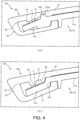
- FIG. 4 is a partially enlarged cross-sectional view of the electronic cymbal 201 according to the second embodiment.
- FIG. 4 in order to simplify the drawing, the hatching of the frame 2 (the bow frame 221) and the cover 204 is omitted.
- the bow frame 221 of the electronic cymbal 201 of the second embodiment has the same configuration as the bow frame 21 of the first embodiment, except for the point where, in place of the recess part 21e of the first embodiment (see FIG. 2 ), the stopper 221g is integrally formed.
- the cover 204 has the same configuration as the cover 4 of the first embodiment except for a point that, in place of the stopper 46 of the first embodiment (see FIG. 2 ), the recess part 249 is formed at the upper cover part 41.
- the stopper 221g protrudes upward from the bow frame 221, and is inserted into the recess part 249 formed on the lower surface of the upper cover part 41. Accordingly, at the time of being struck from the lateral direction, through the catching between the stopper 221g and the recess part 249, the deformation of the upper cover part 41 toward the inner peripheral side can be limited. Thus, since the upper cover part 41 and the lateral cover part 42 can be suppressed from contacting the sensor installation part 21d at the time of being struck from the lateral direction, the protrusion 45 is easily pressed to the edge sensor 5.
- the stopper 221g faces the space S1 between the sensor installation part 21d and the upper cover part 41, and there is no rubber filling the outer peripheral side of the stopper 221g. Accordingly, the upper cover part 41 is easily deformed with the stopper 221g as the fulcrum, and thus the protrusion 45 is easily pressed to the edge sensor 5 at the time of being struck from the respective directions.
- the upper surface of the sensor installation part 21d (the edge sensor 5) and the lower surface of the protrusion 45 are formed to be parallel, and the angles of the respective surfaces provide slopes greater than the upper surface of the covered part 21a. Accordingly, the angle of the upper surface of the sensor installation part 21d (the edge sensor 5) with respect to the horizontal direction can be increased. Thus, even if the protrusion 45 is displaced toward the inner peripheral side due to the striking from the lateral direction, the edge sensor 5 is easily pressed by the protrusion 45.
- connection position P2 between the upper cover part 41 and the lateral cover part 42 can be away from the outer edge of the sensor installation part 21d.
- the protrusion 45 is easily pressed to the edge sensor 5. Accordingly, the sensitivity of the edge sensor 5 with respect to the striking from the lateral direction can be facilitated.
- FIG. 4 is a partially enlarged cross-sectional view of the electronic cymbal 301 according to the third embodiment.
- FIG. 4 in order to simplify the drawing, the hatching of the frame 2 (a bow frame 321) and a cover 304 is omitted.
- the bow frame 321 of the electronic cymbal 301 of the third embodiment has the same configuration as the bow frame 21 of the first embodiment, except for the point that the overhang part 21c of the first embodiment (see FIG. 2 ) is omitted, and the sensor installation part 21d is integrally formed at the lower end of the bent part 21b.
- cover part 304 has the same configuration as the cover 4 of the first embodiment, except for the point that the upper cover part 41 (a portion on the outer peripheral side with respect to the stopper 46) or the protrusion 45 is formed to be thicker and the point that the lower cover part 43 omitting the contact part 48 (see FIG. 2 ) makes contact along the lower surface of the sensor installation part 21d.
- the deformation of the upper cover part 41 toward the inner peripheral side can be limited at the time of being struck from the lateral direction.
- the upper cover part 41 and the lateral cover part 42 can be suppressed from contacting the outer edge portion of the sensor installation part 21d at the time of being struck from the lateral direction, the protrusion 45 is easily pressed to the edge sensor 5.
- the stopper 46 faces the space S1 between the sensor installation part 21d and the upper cover part 41, and there is no rubber filling the outer peripheral side of the stopper 46. Accordingly, since the upper cover part 41 is easily deformed with the stopper 46 as the fulcrum, the protrusion 45 is easily pressed to the edge sensor 5 at the time of being struck from the respective directions.
- the upper surface of the sensor installation part 21d (the edge sensor 5) and the lower surface of the protrusion 45 are formed to be parallel, and the angles of the respective surfaces provide slopes greater than the upper surface of the covered part 21a. Accordingly, a larger angle of the upper surface of the sensor installation part 21d (the edge sensor 5) with respect to the horizontal direction can be ensured, and thus even if the protrusion 45 is displaced toward the inner peripheral side due to the striking from the lateral direction, the edge sensor 5 is easily pressed by the protrusion 45.
- connection position P2 between the upper cover part 41 and the lateral cover part 42 can be away from the outer edge of the sensor installation part 21d.
- the protrusion 45 is easily pressed to the edge sensor 5. Accordingly, the sensitivity of the edge sensor 5 with respect to the striking from the lateral direction can be facilitated.
- the frame 2 includes the disc-shaped bell frame 20 and the bow frame 21, 221, and 321, that is, the case in which the electronic cymbal 1, 201, 301 is an electronic percussion instrument simulating the cymbal.
- the invention is not limited thereto.
- the invention may also be applicable to an edge portion of another disc-shaped electronic percussion instrument.
- the outer shape of the frame 2 is not limited to being circular (disc-shaped).
- the outer shape of the frame 2 may also be polygonal.
- the case where the lower surface of the protrusion 45 of the upper cover part 41 is parallel to the upper surface of the sensor installation part 21d (the edge sensor 5) is described.
- the invention is not limited thereto.
- the slope of the lower surface of the protrusion 45 may also be configured as being greater or less than that of the upper surface of the sensor installation part 21d (the edge sensor 5), and the protrusion 45 may also be omitted.
- the slope of the upper surface of the sensor installation part 21d (the edge sensor 5) is greater than the upper surface of the covered part 21a is described.
- the invention is not limited thereto.
- the slope of the upper surface of the sensor installation part 21d may also be configured as being the same as or less than the slope of the upper surface of the covered part 21a.
- the configuration in which the interval between the sensor installation part 21d (the edge sensor 5) and the upper cover part 41 is gradually increased is described.
- the invention is not limited thereto.
- the interval between the sensor installation part 21d (the edge sensor 5) and the upper cover part 41 may also remain the same or be gradually decreased from the inner peripheral side to the outer peripheral side.
- the bonding position P1 between the bow frame 21, 221, 321 and the bonding part 44 is located on the inner peripheral side with respect to the stopper 46, 221g.
- the invention is not limited thereto.
- the bonding position P1 may also be located on the outer peripheral side with respect to the stopper 46, 221g, the bonding part 44 may be omitted, and the inner edge of the lower cover part 43 is directly bonded to the lower surface of the bow frame 21, 221, 321.
- the upper cover part 41 or the bow frame 221 includes the stopper 46, 221g limiting the deformation of the upper cover part 41 toward the inner peripheral side is described.
- the invention is not limited thereto.
- the stopper 46, 221g may be omitted.
- a portion of the step difference portion (the space S2) between the overhang part 21c and the sensor installation part 21d is filled by the contact part 48.
- the contact part 48 may also completely fill the step difference portion (the space S2), or the contact part 48 may also be omitted.
- the stopper 46 may contact the wall surface (the outer peripheral surface of the bent part 21b) of the recess part 21e in the pre-striking state.
- the wall surface (the outer peripheral surface of the bent part 21b) on the inner peripheral side of the recess part 21e and the stopper 46 may be separated from the stopper 46 as long as the pressing to the edge sensor 5 by the protrusion 45 does not become insufficient.
- the first embodiment describes the case where a gap is formed between the sensor installation part 21d and the stopper 46
- the invention is not limited thereto.
- the sensor installation part 21d and the stopper 46 may also be connected with each other in the pre-striking state.
- the first embodiment describes the case where the thickness of the upper cover part 41 in the thin part 47 is gradually reduced toward the stopper 46, but the invention is not limited thereto.
- the thickness of the upper cover part 41 in the thin part 47 may also be constant.
- the thin part 47 is omitted, and the thickness of the upper cover part 41 (the region where the protrusion 45 or the stopper 46 is not formed) may also remain constant. That is, if it is configured that the upper cover part 41 (the protrusion 45) can be deformed to the side of the edge sensor 5 by the stopper 46 as the fulcrum, the thickness of the upper cover part 41 can be set as appropriate.
Landscapes
- Physics & Mathematics (AREA)
- Engineering & Computer Science (AREA)
- Acoustics & Sound (AREA)
- Multimedia (AREA)
- General Physics & Mathematics (AREA)
- Electrophonic Musical Instruments (AREA)
Abstract
Description
- The invention relates to an electronic cymbal and a striking detection method, and particularly relates to an electronic cymbal and a striking detection method capable of facilitating the sensor sensitivity with respect to striking from a lateral direction.
- An electronic cymbal including a frame, an edge sensor installed to an upper surface on an outer edge side of the frame, and a cover covering an upper surface of the frame in a state in which a space is formed between the edge sensor and the cover and detecting striking to an outer edge portion of the cover (frame) by the edge sensor is known.
- For example,
Patent Document 1 recites an electronic cymbal including an upper cover part 5b1 covering an upper surface of aframe 4 and a lower cover part 5b2 with coverage from an outer edge (outer peripheral surface) of theframe 4 to an edge part of a lower surface. In such technique, a protrusion part 5b3 protruding toward an edge sensor 7b is formed in the upper cover part 5b1, and when the performer strikes an outer edge portion of the upper cover part 5b1 from the top by a stick, etc., due to elastic deformation (bending) of the upper cover part 5b1, the protrusion part 5b3 is pressed to the edge sensor 7b. Accordingly, the striking to the outer edge portion of the cover 5 (the frame 4) is detected by the edge sensor 7b. - [Patent Document 1]
Japanese Laid-open No. 2021-026077 FIG. 4 ) - However, in the conventional technology, when the outer edge portion of the
cover 5 is struck in a state in which the stick is upright (referred to striking from the lateral direction), before the protrusion part 5b3 is pressed to the edge sensor 7b, the upper cover 5b1 or the lower cover part 5b2 may contact the outer edge of theframe 4. When such contact occurs, since the pressing of the edge sensor 7b due to the protrusion part 5b3 is insufficient, an issue that the sensitivity of the edge sensor 7b with respect to the striking from the lateral direction may be low arises. - The invention has been made to solve the above issue, and an objective of the invention is to provide an electronic cymbal and a striking detection method capable of facilitating the sensor sensitivity with respect to the striking from the lateral direction.
- In order to achieve the objective, an electronic cymbal according to an aspect of the invention includes: a plate-like frame; a sensor installed to an upper surface on an outer edge side of the frame; and a cover covering upper surfaces of the sensor and the frame. The cover includes an upper cover part covering the upper surface of the frame in a state in which a space is formed between the upper cover part and the sensor; a lateral cover part extending from an outer edge of the upper cover part and covering an outer peripheral surface of the frame in a state in which a space is formed between the lateral cover part and an outer peripheral surface of the frame; and a lower cover part, extending from a lower end of the lateral cover part to an inner peripheral side and covering a lower surface of the frame. The upper cover part or the frame comprises a stopper facing the space between the upper cover part and the sensor and limits deformation of the upper cover part toward an inner peripheral side.
- An electronic cymbal according to another aspect of the invention includes: a plate-like frame; a sensor installed to an upper surface on an outer edge side of the frame; and a cover covering upper surfaces of the sensor and the frame. The cover includes an upper cover part covering the upper surface of the frame in a state in which a space is formed between the upper cover part and the sensor; a lateral cover part extending from an outer edge of the upper cover part and covering an outer peripheral surface of the frame in a state in which a space is formed between the lateral cover part and an outer peripheral surface of the frame; and a lower cover part, extending from a lower end of the lateral cover part to an inner peripheral side and covering a lower surface of the frame. The frame includes: a covered part covered in a state of being contacted by the upper cover part; and a sensor installation part which is located on an outer peripheral side with respect to the covered part and to which the sensor is installed. The upper cover part includes a protrusion which protrudes toward the sensor and in which a lower surface is parallel to an upper surface of the sensor installation part. The upper surface of the sensor installation part tilts downward toward an outer peripheral side at a slope greater than that of an upper surface of the covered part, and an interval between the upper surface of the sensor installation part and the lower surface of the upper cover part is formed to gradually increase from an inner peripheral side toward the outer peripheral side.
- Another aspect of the invention provides a striking detection method for an electronic cymbal. The electronic cymbal includes: a plate-like frame; a sensor installed to an upper surface on an outer edge side of the frame; and a cover covering upper surfaces of the sensor and the frame. The cover includes: an upper cover part covering the upper surface of the frame in a state in which a space is formed between the upper cover part and the sensor; a lateral cover part extending from an outer edge of the upper cover part and covering an outer peripheral surface of the frame in a state in which a space is formed between the lateral cover part and an outer peripheral surface of the frame; and a lower cover part, extending from a lower end of the lateral cover part to an inner peripheral side and covering a lower surface of the frame. The upper cover part or the frame includes a stopper facing the space between the upper cover part and the sensor. The striking detection method includes: at the time of striking an outer edge of the cover, limiting deformation of the upper cover part toward an inner peripheral side by the stopper and detecting striking to the cover by pressing the sensor by the upper cover part deformed with the stopper as a fulcrum.
- Another aspect of the invention provides a striking detection method for an electronic cymbal. The electronic cymbal includes: a plate-like frame; a sensor installed to an upper surface on an outer edge side of the frame; and a cover covering upper surfaces of the sensor and the frame. The cover includes: an upper cover part covering the upper surface of the frame in a state in which a space is formed between the upper cover part and the sensor; a lateral cover part extending from an outer edge of the upper cover part and covering an outer peripheral surface of the frame in a state in which a space is formed between the lateral cover part and an outer peripheral surface of the frame; and a lower cover part, extending from a lower end of the lateral cover part to an inner peripheral side and covering a lower surface of the frame. The frame includes: a covered part covered in a state of being contacted by the upper cover part; and a sensor installation part which is located on an outer peripheral side with respect to the covered part and to which the sensor is installed. The upper cover part includes a protrusion which protrudes toward the sensor and in which a lower surface is parallel to an upper surface of the sensor installation part. The upper surface of the sensor installation part tilts downward toward an outer peripheral side at a slope greater than that of an upper surface of the covered part, and an interval between the upper surface of the sensor installation part and the lower surface of the upper cover part is formed to gradually increase toward the outer peripheral side. The striking detection method includes: at the time of striking the outside of the cover, suppressing the upper cover part and the lateral cover part from contacting an outer edge of the sensor installation part, and detecting striking to the cover by pressing the sensor by the protrusion displaced together with deformation of the upper cover part.
-
-
FIG. 1 is a cross-sectional view illustrating an electronic cymbal according to a first embodiment. -
FIG. 2 is a partially enlarged cross-sectional view of the electronic cymbal in which a portion II ofFIG. 1 is enlarged. - In
FIG. 3, (a) is a partially enlarged cross-sectional view of the electronic cymbal illustrating a state in which an edge portion is struck by normal striking, and (b) is a partially enlarged cross-sectional view of the electronic cymbal illustrating a state in which the edge portion is struck by striking from a lateral direction. - In
FIG. 4, (a) is a cross-sectional view illustrating an electronic cymbal according to a second embodiment, and (b) is a cross-sectional view illustrating an electronic cymbal according to a third embodiment. - Hereinafter, several embodiments will be described with reference to the accompanying drawings. Firstly, the overall configuration of an
electronic cymbal 1 is described with reference toFIG. 1. FIG. 1 is a cross-sectional view illustrating anelectronic cymbal 1 according to a first embodiment.FIG. 1 illustrates an end surface cut at a plane along a central axis of aframe 2 that is disc-shaped (the same applies toFIG. 2 and subsequent drawings). In addition, in the following description, the description is made by setting the direction along the central axis of the disc-shaped frame 2 as upper-lower direction and a direction (radial direction) orthogonal to the upper-lower direction as a left-right direction. - As shown in
FIG. 1 , theelectronic cymbal 1 is an electronic percussion instrument that simulates an acoustic cymbal (referred to as "cymbal" in the following). The skeleton of theelectronic cymbal 1 is formed by theframe 2. - The
frame 2 is a frame made of resin and including abell frame 20 that simulates the shape of a bell of the cymbal and abow frame 21 that simulates the shape of a bow of the cymbal. Thebell frame 20 is formed in a bowl shape tilting downward from the central side thereof toward the outer peripheral side, and thebow frame 21 extends from the outer edge of thebell frame 20 toward the outer peripheral side (the outer side in the left-right direction). - The
bow frame 21 gradually tilts downward with respect to thebell frame 20 toward the outer peripheral side, and theframe 2 as a whole is formed in a substantially disc shape by integrally forming thebell frame 20 and thebow frame 21. - A through
hole 22 is formed at the center of thebell frame 20, and aninner wall part 30 of a case 3 is caught to the throughhole 22. Theinner wall part 30 is formed in a substantially cylindrical shape, and the inner peripheral side of the inner wall part 30 (the inner side in the left-right direction) is blocked by a disc-shaped support part 32 having a throughhole 31 at the center. A rod (not shown) for supporting theelectronic cymbal 1 is inserted into thethrough hole 31 of thesupport part 32. - A
bottom wall part 33 extends from the lower end of theinner wall part 30 toward the outer peripheral side. By fixing the outer edge of thebottom wall part 33 to the lower surface of the frame 2 (the bow frame 21), a space surrounded by theframe 2 and the case 3 is formed on the lower surface side of theframe 2. Electronic components, such as a striking sensor (not shown), a substrate (not shown) etc., installed to the lower surface of thebell frame 20 is stored in the space. The striking sensor is a piezoelectric element detecting the vibration of theframe 2. - The upper surface of each of the
bell frame 20 and thebow frame 21 is covered by acover 4 made of rubber and having a throughhole 40 at the center, and thecover 4 is formed in a shape (substantially disc shape) along each of theframes cover 4 and thebell frame 20, and the bell part sensor is a pressure sensor (e.g., a membrane switch) that is sheet-like and is ON/OFF when thecover 4 covering thebell frame 20 is struck. - The striking to the
bell frame 20 is detected by the bell part sensor, and the striking to thebow frame 21 is detected by the striking sensor. In addition, as will be explicated in the following, the striking to the edge (outer edge) portion of thebow frame 21 is detected by anedge sensor 5. The striking detected by each sensor is converted into an electrical signal and output to a sound source device not shown herein. Accordingly, a musical sound in accordance with a striking position to theelectronic cymbal 1 is generated. - Then, referring to
FIG. 2 and(a) and(b) ofFIG. 3 , the detailed configuration of the edge portion of theelectronic cymbal 1 and the function at the time when the edge portion is struck are described. -
FIG. 2 is a partially enlarged cross-sectional view of theelectronic cymbal 1 in which a portion II ofFIG. 1 is enlarged. InFIG. 3, (a) is a partially enlarged cross-sectional view of theelectronic cymbal 1 illustrating a state in which an edge portion is struck by normal striking, and (b) is a partially enlarged cross-sectional view of theelectronic cymbal 1 illustrating a state in which the edge portion is struck by striking from a lateral direction. InFIG. 2 and(a) and (b) ofFIG. 3 , in order to simplify the drawings, the hatching of the frame 2 (the bow frame 21) and thecover 4 is omitted. - In addition, normal striking refers to striking to the outer edge of an
upper cover part 41 from the top in a state in which a stick S is slanted (at an angle close to being horizontal), and striking from the lateral direction refers to striking to the outer edge portion of theupper cover part 41 from the lateral direction in a state in which the stick S is upright (at an angle close to the vertical direction). In addition, each configuration of theelectronic cymbal 1 described in the following is formed to be continuous in the peripheral direction. However, a portion of the configuration may also be intermittent in the peripheral direction. - As shown in
FIG. 2 , thecover 4 includes theupper cover part 41 covering the upper surface side of thebow frame 21, alateral cover part 42 extending downward from the outer edge (the end part on the left side ofFIG. 2 ) of theupper cover part 41, alower cover part 43 extending from the lower end of thelateral cover part 42 toward the inner peripheral side (the right side ofFIG. 2 ), and abonding part 44 bent upward from the inner edge of thelower cover part 43. Theparts 41 to 44 are integrally formed. - The
upper cover part 41 is bonded to the upper surface of thebow frame 21 by a double-side tape 6, and the upper surface of thebonding part 44 is bonded to the lower surface of thebow frame 21 by an adhesive. Meanwhile, on the outer peripheral side with respect to these bonded portions, neither of theupper cover part 41, thelateral cover part 42, and thelower cover part 43 is bonded to thebow frame 21. - As described in the following, within the
bow frame 21, a portion bonded to the upper cover part 41 (i.e., a portion covered in a state of being contacted by the upper cover part 41) is described as acovered part 21a. - A
bent part 21b is bent downward from the outer edge of thecovered part 21a, anoverhang part 21c overhangs from the lower end of thebent part 21b toward the outer peripheral side. In addition, asensor installation part 21d extends from the upper end on the outer edge side of theoverhang part 21c to the outer peripheral side. By integrally forming the respective parts of thecovered part 21a, thebent part 21b, theoverhang part 21c, and thesensor installation part 21d, the edge portion of thebow frame 21 is formed. - The
edge sensor 5 is bonded to the upper surface of thesensor installation part 21d, and theedge sensor 5 is also a sheet-like pressure sensor (e.g., a membrane switch) like the bell part sensor. Theupper cover part 41 covers thebow frame 21 in a state in which a space S1 is formed between theupper cover part 41 and the edge sensor 5 (thesensor installation part 21d). - A
protrusion 45 protruding toward the edge sensor 5 (downward) is integrally formed on the lower surface of theupper cover part 41. Theprotrusion 45 is a portion pressing theedge sensor 5 at the time when the outer edge portion of theupper cover part 41 is struck. - A
stopper 46 integrally formed with theupper cover part 41 is provided on the inner peripheral side with respect to theprotrusion 45. Thestopper 46 is a protrusion protruding downward from theupper cover part 41 and inserted into arecess part 21e formed on the upper surface of thebow frame 21. Therecess part 21e is a groove formed by thebent part 21b, theoverhang part 21c, and thesensor installation part 21d of thebow frame 21. - In a state before the
upper cover part 41 is struck (referred to as "pre-striking state" in the following), thestopper 46 and the bottom surface of therecess part 21e are in contact with each other or slightly separated (less than a gap between theprotrusion 45 and the edge sensor 5). - Accordingly, as shown in (a) of
FIG. 3 , when the outer edge portion of theupper cover part 41 is struck from the top through normal striking, thestopper 46 contacting the bottom surface of therecess part 21e (the upper surface of theoverhang part 21c) serves as the fulcrum, and theupper cover part 41 is elastically deformed to be bent downward. - As the
upper cover part 41 deforms downward, thelateral cover part 42 and thelower cover part 43 deform downward so as to be separated from the bow frame 21 (theoverhang part 21c and thesensor installation part 21d). This is because, as described above, thelateral cover part 42 and thelower cover part 43 are not bonded to thebow frame 21 on the outer peripheral side with respect to thebonding part 44. - Through the downward deformation of the
respective cover parts protrusion 45 is pressed to theedge sensor 5, and the striking to the cover 4 (the upper cover part 41) by the stick S is detected by theedge sensor 5. - Meanwhile, as shown in (b) of
FIG. 3 , when theupper cover part 41 is struck from the lateral direction, due to the catching between thestopper 46 and the wall surface of therecess part 21e (the outer peripheral surface of thebent part 21b), the deformation (displacement) of theupper cover part 41 toward the inner peripheral side is limited. By limiting the deformation of theupper cover part 41 toward the inner peripheral side, the contact of theupper cover part 41 and thelateral cover part 42 to the outer edge portion of thesensor installation part 21d can be suppressed. Therefore, theprotrusion 45 can be easily suppressed to theedge sensor 5. Accordingly, the sensitivity of theedge sensor 5 with respect to the striking from the lateral direction can be facilitated. - In addition, in the pre-striking state (the state of
FIG. 2 ), thestopper 46 faces the space S1, and there is no rubber filling the space S1 on the outer peripheral side of thestopper 46. Therefore, theupper cover part 41 is easily deformed to bend with the root portion of thestopper 46 as the start point. Accordingly, for example, even in the case where the outer edge portion of theupper cover part 41 is struck lightly from the lateral direction (see (b) ofFIG. 3 ), theprotrusion 45 is easily pressed to theedge sensor 5. Accordingly, the sensitivity of theedge sensor 5 with respect to the striking from the lateral direction can be facilitated. - Moreover, with the deformation of the
upper cover part 41 toward the inner peripheral side being limited by thestopper 46, the force applied to the bonding portion (the double-side tape 6) between thecovered part 21a and theupper cover part 41 can be reduced. Accordingly, theupper cover part 41 can be prevented from being peeled off from the coveredpart 21a. - In addition, a bonding position P1 between the
bonding part 44 and the lower surface of thebow frame 21 is located on the inner peripheral side with respect to thestopper 46, and neither of thelateral cover part 42 and thelower cover part 43 is bonded to thebow frame 21 on the outer peripheral side with respect to the bonding position P1. Accordingly, in both (referred to as "striking from the respective directions" in the following) of the normal striking (see (a) ofFIG. 3 ) and the striking from the lateral direction (see (b) ofFIG. 3 ), thelateral cover part 42 and thelower cover part 43 easily follow the deformation of theupper cover part 41 with thestopper 46 as the fulcrum. That is, the deformation of theupper cover part 41 can be prevented from being obstructed by thelateral cover part 42 and thelower cover part 43. Therefore, theprotrusion 45 is easily pressed to toward theedge sensor 5. Accordingly, the sensitivity of theedge sensor 5 with respect to the striking from the respective directions can be facilitated. - In addition, although the
lower cover part 43 is also deformed at the time of being struck from the lateral direction, the deformation of thelower cover part 43 is limited by aprotrusion part 21f Theprotrusion part 21f protrudes downward from the lower surface of thebow frame 21, and thebonding part 44 is inserted between a protrusive portion formed by thebent part 21b, theoverhang part 21c, and thesensor installation part 21d on the lower surface of thebow frame 21 and theprotrusion part 21f. - Accordingly, since the deformation of the
lower cover part 43 and thebonding part 44 toward the inner peripheral side at the time of being struck from the lateral direction (see (b) ofFIG. 3 ) is limited by theprotrusion part 21f, theupper cover part 41 and thelateral cover part 42 can be suppressed from contacting the outer edge portion of thesensor installation part 21d. Thus, since theprotrusion 45 is easily pressed to theedge sensor 5, the sensitivity of theedge sensor 5 with respect to the striking from the lateral direction can be facilitated. Moreover, by limiting the deformation thelower cover part 43 and thebonding part 44 toward the inner peripheral side by theprotrusion part 21f, the force applied to the bonding position P1 between thebow frame 21 and thebonding part 44 can be reduced, and thebonding part 44 can be suppressed from being peeled off from thebow frame 21. - In addition, in order to easily deform the
upper cover part 41 by setting thestopper 46 as the fulcrum, athin part 47 is formed at theupper cover part 41. More specifically, except for regions in which theprotrusion 45 and thethin part 47 are formed, the thickness of theupper cover part 41 is substantially constant in regions on the outer peripheral side with respect to thestopper 46. Here, "being substantially constant" means that, compared with the averaged thickness of theupper cover part 41 in such regions, the minimum thickness and the maximum thickness of theupper cover part 41 are within ± 10% of the averaged thickness. Meanwhile, in the region in which thethin part 47 is formed, the thickness of theupper cover part 41 is thinner than other regions, and the thickness of theupper cover part 41 is gradually reduced toward thestopper 46. - By forming such
thin part 47 in an adjacent portion to the outer peripheral surface of thestopper 46, at the time of being struck from the respective directions (see (a) and (b) ofFIG. 3 ), theupper cover part 41 is easily deformed with the root portion of thestopper 46 as the start point. Accordingly, for example, even in the case where the outer edge portion of theupper cover part 41 is struck lightly, the sensitivity of theedge sensor 5 with respect to the striking from the respective directions can be facilitated. - In this way, although the deformation of the
upper cover part 41 toward the inner peripheral side is limited by thestopper 46 formed at theupper cover part 41 in the embodiment, the deformation of theupper cover part 41 toward the inner peripheral side can also be limited even in a configuration in which astopper 221g protruding upward from abow frame 221 is fit to arecess part 249 of acover 204 in a second embodiment (see (a) ofFIG. 4 ) to be described in the following, for example. However, in such configuration, since the thickness of the region of thecover 204 where therecess part 249 is formed is reduced, thecover 204 is less durable with respect to striking. When the thickness of thecover 204 is increased to ensure the durability, the overall thickness of theelectronic cymbal 201 is increased, and it is difficult to keep the shape flat like the cymbal. - Comparatively, in the embodiment, it is configured that the
bent part 21b bent downward from the outer edge of thecovered part 21a is formed at thebow frame 21, thestopper 46 located on the outer peripheral side of thebent part 21b is formed at theupper cover part 41, and the deformation of theupper cover part 41 toward the inner peripheral side is limited by thebent part 21b and thestopper 46. Accordingly, compared with the configuration in which thestopper 221g of thebow frame 221 is inserted into therecess part 249 of thecover 204 as in the second embodiment, the thickness of thecover 4 is ensured, and the overall thickness of thebow frame 21 and thecover 4 can be reduced. Accordingly, theelectronic cymbal 1 can be in a shape similar to the cymbal. - Here, the deformation of the
upper cover part 41 toward the inner peripheral side can be generally limited by thestopper 46. However, at the time of being struck strongly from the lateral direction, for example, theprotrusion 45 of theupper cover part 41 is displaced toward the inner peripheral side (the inner side along the left-right direction) instead of being displaced downward. In the case where theprotrusion 45 is displaced toward the inner peripheral side, the closer the angle of the upper surface of thesensor installation part 21d (the edge sensor 5) is to being horizontal, the more likely theedge sensor 5 is pressed insufficiently by theprotrusion 45. - Comparatively, in the embodiment, the upper surface of the
sensor installation part 21d (the edge sensor 5) and the lower surface of theprotrusion 45 are formed to be parallel, and the respective surfaces tilt downward toward the outer peripheral side at a slope greater than that of the upper surface of thecovered part 21a. Accordingly, a larger angle of the upper surface of thesensor installation part 21d (the edge sensor 5) with respect to the left-right direction (horizontal direction) can be ensured. Thus, even in the case where theprotrusion 45 is displaced toward the inner peripheral side due to the striking from the lateral direction, theedge sensor 5 is easily pressed by theprotrusion 45. Therefore, the sensitivity of theedge sensor 5 with respect to the striking from the lateral direction can be facilitated. - In addition, the slope of the upper surface of the
sensor installation part 21d is greater than that of the upper surface of the coveredpart 21, whereas the lower surface of the upper cover part 41 (the portion without theprotrusion 45 and the thin part 47) is parallel to the upper surface of thecovered part 21a. That is, the lower surface of theupper cover part 41 tilts downward toward the outer peripheral side at a slope less than that of the upper surface of thesensor installation part 21d. - Accordingly, an interval between the upper surface of the
sensor installation part 21d and the lower surface of theupper cover part 41 is gradually increased from the inner peripheral side to the outer peripheral side. Therefore, a connection position P2 between theupper cover part 41 and thelateral cover part 42 can be away from the outer edge of thesensor installation part 21d. Thus, at the time of being struck from the lateral direction, theupper cover part 41 and thelateral cover part 42 can be suppressed from contacting the outer edge portion of thesensor installation part 21d. Accordingly, since theprotrusion 45 is easily pressed to theedge sensor 5, the sensitivity of theedge sensor 5 with respect to the striking from the lateral direction can be facilitated. - In this way, in the embodiment, by limiting the deformation of the
upper cover part 41 toward the inner peripheral side by thestopper 46, or by increasing the slope of the upper surface of thesensor installation part 21d (the edge sensor 5), the sensitivity of theedge sensor 5 with respect to the striking from the lateral direction can be facilitated. - Comparatively, referring to a third embodiment (see (b) of
FIG. 4 ) to be described afterwards, for example, even in a configuration in which theoverhang part 21c is omitted, and thesensor installation part 21d is provided at the lower end of thebent part 21b, it is still possible to exert the function of thestopper 46. However, in the configuration in which thesensor installation part 21d with a larger slope is connected to the lower part of thebent part 21b, thesensor installation part 21d significantly protrudes downward from thebow frame 21. That is, since the thickness of the edge portion of thebow frame 21 is increased, it is difficult to keep the shape of anelectronic cymbal 301 flat like the cymbal. - Comparatively, in the embodiment, it is configured that the
overhang part 21c which overhangs from the lower end of thebent part 21b toward the outer peripheral side is provided, and thesensor installation part 21d is provided at the upper end part on the outer edge side of theoverhang part 21c. In this way, compared with the configuration in which theoverhang part 21c is omitted, the arrangement (height) of thesensor installation part 21d can be increased. Therefore, the significant downward protrusion of thesensor installation part 21d can be suppressed. Accordingly, the thickness of the edge portion of thebow frame 21 can be reduced, and theelectronic cymbal 1 can be in a flat shape like the cymbal. - Here, in addition to the function of detecting the striking to the
upper cover part 41, theedge sensor 5 is also provided with a function of detecting a choke playing technique in which the performer grabs the edge portion of thebow frame 21. A conventional process may be adopted for the process of distinguishing between the striking to theupper cover part 41 and the choke playing technique. Therefore, details in this regard will be omitted. As a conventional process, a process described in para. 0005 to 0008 ofJapanese Laid-open No. H06-035450 - In such choke playing technique, as described above, the performer grabs the edge portion of the
bow frame 21. In such case, when thesensor installation part 21d is provided at the upper end part on the outer edge side of theoverhang part 21c, a step difference is formed in the connection portion between theoverhang part 21c and thesensor installation part 21d, and a space S2 (seeFIG. 2 ) is created between the step difference portion and thelower cover part 43. Therefore, the feeling when performing the choke playing technique deteriorates. That is, when the space S2 is formed to be large, a hard feeling like the cymbal cannot be obtained. - Comparatively, the
lower cover part 43 of the embodiment includes acontact part 48 which fills a portion of the step difference formed by theoverhang part 21c and thesensor installation part 21d. Thecontact part 48 is a protrusion integrally formed with the upper surface of thelower cover part 43, and contacts the lower surface of thesensor installation part 21d in the pre-striking state (the state shown in (a) and (b) ofFIG. 2 ). Accordingly, when the performer grabs the vicinity of thecontact part 48 to perform the choke playing technique, a relatively hard feeling can be applied, so the electronic cymbal can provide a feeling of performance close to the cymbal. - To provide the hard feeling close to the cymbal, the space S2 may be completely filled by the
contact part 48. However, when the space S2 is completely filled by thecontact part 48, due to a dimension error of theframe 2 or thecover 4, it is difficult to properly fit thecontact part 48 to the step difference portion between theoverhang part 21c and thesensor installation part 21d. In addition, when the space S2 is completely filled by thecontact part 48, the deformation of theupper cover part 41 is obstructed by the catching between theoverhang part 21c and thecontact part 48, and it is difficult to press theprotrusion 45 to theedge sensor 5. - Comparatively, in the embodiment, a gap is formed between the
overhang part 21c and thecontact part 48, and a portion of the space S2 is left. Accordingly, even if a dimension error occurs in theframe 2 or thecover 4, thecontact part 48 can still be properly fit to the step difference portion between theoverhang part 21c and thesensor installation part 21d. Therefore, the assemblability of thecover 4 can be facilitated. Moreover, since the space S2 is left, at the time of being struck from the respective directions (see (a) and (b) ofFIG. 3 ), thecontact part 48 can be suppressed from being caught by theoverhang part 21c. Therefore, theupper cover part 41 is deformed easily with thestopper 48 as the fulcrum. Thus, since theprotrusion 45 is easily pressed to theedge sensor 5, the sensitivity of theedge sensor 5 with respect to the striking from the respective directions can be facilitated. - In addition, as described above, although the
stopper 46 is inserted into therecess part 21e, a gap is also formed betweenstopper 46 and the wall surface on the outer peripheral side of therecess part 21e (thesensor installation part 21d) in the pre-striking state. Accordingly, even if a dimension error occurs in theframe 2 or thecover 4, thestopper 46 can be properly inserted into therecess part 21e. Therefore, the assemblability of thecover 4 can be facilitated. - Then, the
electronic cymbal 201 of the second embodiment is described with reference to (a) ofFIG. 4 . In the first embodiment, the case where thestopper 46 is formed in thecover 4 is described. However, in the second embodiment, the case where thestopper 221g is formed at thebow frame 221 is described. It is noted that components same as those of the first embodiment are labelled with the same reference symbols, and the description thereof is omitted. InFIG. 4, (a) is a partially enlarged cross-sectional view of theelectronic cymbal 201 according to the second embodiment. In (a) ofFIG. 4 , in order to simplify the drawing, the hatching of the frame 2 (the bow frame 221) and thecover 204 is omitted. - As shown in (a) of
FIG. 4 , thebow frame 221 of theelectronic cymbal 201 of the second embodiment has the same configuration as thebow frame 21 of the first embodiment, except for the point where, in place of therecess part 21e of the first embodiment (seeFIG. 2 ), thestopper 221g is integrally formed. Also, thecover 204 has the same configuration as thecover 4 of the first embodiment except for a point that, in place of thestopper 46 of the first embodiment (seeFIG. 2 ), therecess part 249 is formed at theupper cover part 41. - The
stopper 221g protrudes upward from thebow frame 221, and is inserted into therecess part 249 formed on the lower surface of theupper cover part 41. Accordingly, at the time of being struck from the lateral direction, through the catching between thestopper 221g and therecess part 249, the deformation of theupper cover part 41 toward the inner peripheral side can be limited. Thus, since theupper cover part 41 and thelateral cover part 42 can be suppressed from contacting thesensor installation part 21d at the time of being struck from the lateral direction, theprotrusion 45 is easily pressed to theedge sensor 5. - Also, in the pre-striking state (the state of (a) of
FIG. 4 ), thestopper 221g faces the space S1 between thesensor installation part 21d and theupper cover part 41, and there is no rubber filling the outer peripheral side of thestopper 221g. Accordingly, theupper cover part 41 is easily deformed with thestopper 221g as the fulcrum, and thus theprotrusion 45 is easily pressed to theedge sensor 5 at the time of being struck from the respective directions. - Also, like the first embodiment, the upper surface of the
sensor installation part 21d (the edge sensor 5) and the lower surface of theprotrusion 45 are formed to be parallel, and the angles of the respective surfaces provide slopes greater than the upper surface of thecovered part 21a. Accordingly, the angle of the upper surface of thesensor installation part 21d (the edge sensor 5) with respect to the horizontal direction can be increased. Thus, even if theprotrusion 45 is displaced toward the inner peripheral side due to the striking from the lateral direction, theedge sensor 5 is easily pressed by theprotrusion 45. - In addition, since an interval between the
sensor installation part 21d and theupper cover part 41 is gradually increased toward the outer peripheral side, the connection position P2 between theupper cover part 41 and thelateral cover part 42 can be away from the outer edge of thesensor installation part 21d. Thus, since theupper cover part 41 and thelateral cover part 42 can be suppressed from contacting thesensor installation part 21d at the time of being struck from the lateral direction, theprotrusion 45 is easily pressed to theedge sensor 5. Accordingly, the sensitivity of theedge sensor 5 with respect to the striking from the lateral direction can be facilitated. - Then, an
electronic cymbal 301 of the third embodiment is described with reference to (b) ofFIG. 4 . In the first embodiment, the case where thesensor installation part 2 1d is connected to theoverhang part 21c is described. However, in the third embodiment, the case where thesensor installation part 21d is connected to the lower end of thebent part 21b is described. InFIG. 4, (b) is a partially enlarged cross-sectional view of theelectronic cymbal 301 according to the third embodiment. In (b) ofFIG. 4 , in order to simplify the drawing, the hatching of the frame 2 (a bow frame 321) and acover 304 is omitted. - As shown in (b) of
FIG.4 , thebow frame 321 of theelectronic cymbal 301 of the third embodiment has the same configuration as thebow frame 21 of the first embodiment, except for the point that theoverhang part 21c of the first embodiment (seeFIG. 2 ) is omitted, and thesensor installation part 21d is integrally formed at the lower end of thebent part 21b. - In addition, the
cover part 304 has the same configuration as thecover 4 of the first embodiment, except for the point that the upper cover part 41 (a portion on the outer peripheral side with respect to the stopper 46) or theprotrusion 45 is formed to be thicker and the point that thelower cover part 43 omitting the contact part 48 (seeFIG. 2 ) makes contact along the lower surface of thesensor installation part 21d. - Even in the embodiment, due to the catching between the
stopper 46 and thebent part 21b, the deformation of theupper cover part 41 toward the inner peripheral side can be limited at the time of being struck from the lateral direction. In this way, since theupper cover part 41 and thelateral cover part 42 can be suppressed from contacting the outer edge portion of thesensor installation part 21d at the time of being struck from the lateral direction, theprotrusion 45 is easily pressed to theedge sensor 5. - In addition, in the pre-striking state (the state of (b) of
FIG. 4 ), thestopper 46 faces the space S1 between thesensor installation part 21d and theupper cover part 41, and there is no rubber filling the outer peripheral side of thestopper 46. Accordingly, since theupper cover part 41 is easily deformed with thestopper 46 as the fulcrum, theprotrusion 45 is easily pressed to theedge sensor 5 at the time of being struck from the respective directions. - Also, like the first embodiment, the upper surface of the
sensor installation part 21d (the edge sensor 5) and the lower surface of theprotrusion 45 are formed to be parallel, and the angles of the respective surfaces provide slopes greater than the upper surface of thecovered part 21a. Accordingly, a larger angle of the upper surface of thesensor installation part 21d (the edge sensor 5) with respect to the horizontal direction can be ensured, and thus even if theprotrusion 45 is displaced toward the inner peripheral side due to the striking from the lateral direction, theedge sensor 5 is easily pressed by theprotrusion 45. - In addition, since an interval between the
sensor installation part 21d and theupper cover part 41 is gradually increased toward the outer peripheral side, the connection position P2 between theupper cover part 41 and thelateral cover part 42 can be away from the outer edge of thesensor installation part 21d. Thus, since theupper cover part 41 and thelateral cover part 42 can be suppressed from contacting thesensor installation part 21d at the time of being struck from the lateral direction, theprotrusion 45 is easily pressed to theedge sensor 5. Accordingly, the sensitivity of theedge sensor 5 with respect to the striking from the lateral direction can be facilitated. - Although the above description has been made based on the embodiments, the invention is not limited to the embodiments, and it can be easily inferred that various improvements and modifications can be made without departing from the spirit of the invention.
- In the respective embodiments, a configuration in which the
frame 2 includes the disc-shapedbell frame 20 and thebow frame electronic cymbal frame 2 is not limited to being circular (disc-shaped). For example, the outer shape of theframe 2 may also be polygonal. - In the respective embodiments, the case where the lower surface of the
protrusion 45 of theupper cover part 41 is parallel to the upper surface of thesensor installation part 21d (the edge sensor 5) is described. However, the invention is not limited thereto. For example, the slope of the lower surface of theprotrusion 45 may also be configured as being greater or less than that of the upper surface of thesensor installation part 21d (the edge sensor 5), and theprotrusion 45 may also be omitted. - In the respective embodiments, the case where the slope of the upper surface of the
sensor installation part 21d (the edge sensor 5) is greater than the upper surface of thecovered part 21a is described. However, the invention is not limited thereto. For example, the slope of the upper surface of thesensor installation part 21d may also be configured as being the same as or less than the slope of the upper surface of thecovered part 21a. - In the respective embodiments, the configuration in which the interval between the
sensor installation part 21d (the edge sensor 5) and theupper cover part 41 is gradually increased is described. However, the invention is not limited thereto. For example, the interval between thesensor installation part 21d (the edge sensor 5) and theupper cover part 41 may also remain the same or be gradually decreased from the inner peripheral side to the outer peripheral side. - In the respective embodiments, the case where the bonding position P1 between the
bow frame bonding part 44 is located on the inner peripheral side with respect to thestopper stopper bonding part 44 may be omitted, and the inner edge of thelower cover part 43 is directly bonded to the lower surface of thebow frame - In the respective embodiments, the case where the
upper cover part 41 or the bow frame 221 (the frame 2) includes thestopper upper cover part 41 toward the inner peripheral side is described. However, the invention is not limited thereto. For example, thestopper - In the first and second embodiments, a portion of the step difference portion (the space S2) between the
overhang part 21c and thesensor installation part 21d is filled by thecontact part 48. However, the invention is not limited thereto. For example, thecontact part 48 may also completely fill the step difference portion (the space S2), or thecontact part 48 may also be omitted. - Although omitted in the description of the first and third embodiments, the
stopper 46 may contact the wall surface (the outer peripheral surface of thebent part 21b) of therecess part 21e in the pre-striking state. However, the wall surface (the outer peripheral surface of thebent part 21b) on the inner peripheral side of therecess part 21e and thestopper 46 may be separated from thestopper 46 as long as the pressing to theedge sensor 5 by theprotrusion 45 does not become insufficient. - Although the first embodiment describes the case where a gap is formed between the
sensor installation part 21d and thestopper 46, the invention is not limited thereto. For example, thesensor installation part 21d and thestopper 46 may also be connected with each other in the pre-striking state. - The first embodiment describes the case where the thickness of the
upper cover part 41 in thethin part 47 is gradually reduced toward thestopper 46, but the invention is not limited thereto. For example, the thickness of theupper cover part 41 in thethin part 47 may also be constant. In addition, it may also be that thethin part 47 is omitted, and the thickness of the upper cover part 41 (the region where theprotrusion 45 or thestopper 46 is not formed) may also remain constant. That is, if it is configured that the upper cover part 41 (the protrusion 45) can be deformed to the side of theedge sensor 5 by thestopper 46 as the fulcrum, the thickness of theupper cover part 41 can be set as appropriate. -
- 1, 201, 301: Electronic cymbal;
- 2: Frame;
- 21, 221, 321: Bow frame (a portion of the frame);
- 21a: Covered part;
- 21b: Bent part;
- 21c: Overhang part;
- 21d: Sensor installation part;
- 46, 221g: Stopper;
- 4: Cover;
- 41: Upper cover part;
- 42: Lateral cover part;
- 43: Lower cover part;
- 45: Protrusion;
- 47: Thin part;
- 48: Contact part;
- 5: Edge sensor (sensor).
Claims (15)
- An electronic cymbal (1, 201, 301), comprising:a plate-like frame (2);a sensor (5) installed to an upper surface on an outer edge side of the frame (2); anda cover (4) covering upper surfaces of the sensor (5) and the frame (2),wherein the cover (4) comprises:an upper cover part (41) covering the upper surface of the frame (2) in a state in which a space (S1) is formed between the upper cover part (41) and the sensor (5);a lateral cover part (42) extending from an outer edge of the upper cover part (41) and covering an outer peripheral surface of the frame (2) in a state in which a space is formed between the lateral cover part (42) and an outer peripheral surface of the frame (2); anda lower cover part (43) extending from a lower end of the lateral cover part (42) to an inner peripheral side and covering a lower surface of the frame (2), andthe upper cover part (41) or the frame (2) comprises a stopper (46, 221g) facing the space (S1) between the upper cover part (41) and the sensor (5) and limits deformation of the upper cover part (41) toward the inner peripheral side.
- The electronic cymbal (1, 201, 301) as claimed in claim 1, wherein the upper cover part (41) is bonded to the upper surface of the frame (2) on the inner peripheral side of the stopper (46, 221g).
- The electronic cymbal (1, 201, 301) as claimed in claim 1, wherein the lower cover part (43) is bonded to a lower surface of the frame (2) on the inner peripheral side with respect to the stopper (46, 221g), and is not bonded to the lower surface of the frame (2) on an outer peripheral side with respect to a position (P1) of the bonding.
- The electronic cymbal (1, 201, 301) as claimed in claim 1, wherein the upper cover part (41) comprises a thin part (47) formed in an adjacent portion to an outer peripheral surface of the stopper (46, 221g).
- The electronic cymbal (1, 201, 301) as claimed in claim 1, wherein
the frame (2) comprises:a covered part (21a) covered in a state of being contacted by the upper cover part (41); anda bent part (21b) bent downward from an outer edge of the covered part (21a),the upper cover part (41) comprises the stopper (46, 221g) protruding toward the frame (2) on an outer peripheral side of the bent part (21b), andthe deformation of the upper cover part (41) toward the inner peripheral side is limited through catching between the bent part (21b) and the stopper (46, 221g). - The electronic cymbal (1, 201, 301) as claimed in claim 5, wherein
the frame (2) comprises:an overhang part (21c) extending from a lower end of the bent part (21b) to an outer peripheral side; anda sensor installation part (21d) which extends from an upper end part on an outer edge side of the overhang part (21c) to the outer peripheral side and to which the sensor (5) is installed,the upper cover part (41) comprises a protrusion (45) which protrudes toward the sensor (5) and in which a lower surface is parallel to an upper surface of the sensor installation part (21d), andthe upper surface of the sensor installation part (21d) tilts downward toward the outer peripheral side at a slope greater than that of an upper surface of the covered part (21a),the lower cover part (43) comprises a contact part (48) contacting a lower surface of the sensor installation part (21d) in a manner of filling at least a portion of a step difference formed by the overhang part (21c) and the sensor installation part (21d). - The electronic cymbal (1, 201, 301) as claimed in claim 6, wherein a gap is formed between the overhang part (21c) and the contact part (48).
- The electronic cymbal (1, 201, 301) as claimed in claim 6 or 7, wherein a gap is formed between the stopper (46, 221g) and the sensor installation part (21d).
- An electronic cymbal (1, 201, 301), comprising:a plate-like frame (2);a sensor (5) installed to an upper surface on an outer edge side of the frame (2); anda cover (4) covering upper surfaces of the sensor (5) and the frame (2),wherein the cover (4) comprises:an upper cover part (41) covering the upper surface of the frame (2) in a state in which a space (S1) is formed between the upper cover part (41) and the sensor (5);a lateral cover part (42) extending from an outer edge of the upper cover part (41) and covering an outer peripheral surface of the frame (2) in a state in which a space is formed between the lateral cover part (42) and an outer peripheral surface of the frame (2); anda lower cover part (43), extending from a lower end of the lateral cover part (42) to an inner peripheral side and covering a lower surface of the frame (2),the frame (2) comprises:a covered part (21a) covered in a state of being contacted by the upper cover part (41); anda sensor installation part (21d) which is located on an outer peripheral side with respect to the covered part (21a) and to which the sensor (5) is installed,the upper cover part (41) comprises a protrusion (45) which protrudes toward the sensor (5) and in which a lower surface is parallel to an upper surface of the sensor installation part (21d), andthe upper surface of the sensor installation part (21d) tilts downward toward an outer peripheral side at a slope greater than that of an upper surface of the covered part (21a), and an interval between the upper surface of the sensor installation part (21d) and the lower surface of the upper cover part (41) is formed to gradually increase toward the outer peripheral side.
- The electronic cymbal (1, 201, 301) as claimed in claim 9, wherein
the frame (2) comprises:a bent part (21b) bent downward from an outer edge of the covered part (21a),the upper cover part (41) comprises a stopper (46, 221g) protruding toward the frame (2) on an outer peripheral side of the bent part (21b) and faces the space (S1) between the upper cover part (41) and the sensor (5), andthe deformation of the upper cover part (41) toward the inner peripheral side is limited through catching between the bent part (21b) and the stopper (46, 221g). - The electronic cymbal (1, 201, 301) as claimed in claim 10, wherein
the frame (2) comprises:an overhang part (21c) extending from a lower end of the bent part (21b) to an outer peripheral side, and the sensor installation part (21d) which extends from an upper end part on an outer edge side of the overhang part (21c) to the outer peripheral side,the lower cover part (43) comprises a contact part (48) contacting a lower surface of the sensor installation part (21d) in a manner of filling at least a portion of a step difference formed by the overhang part (21c) and the sensor installation part (21d), - The electronic cymbal (1, 201, 301) as claimed in claim 11, wherein a gap is formed between the overhang part (21c) and the contact part (48).
- The electronic cymbal (1, 201, 301) as claimed in claim 11 or 12, wherein a gap is formed between the stopper (46, 221g) and the sensor installation part (21d).
- A striking detection method for an electronic cymbal (1, 201, 301), the electronic cymbal (1, 201, 301) comprising:a plate-like frame (2);a sensor (5) installed to an upper surface on an outer edge side of the frame; anda cover (4) covering upper surfaces of the sensor (5) and the frame (2),wherein the cover (4) comprises:an upper cover part (41) covering the upper surface of the frame (2) in a state in which a space (S1) is formed between the upper cover part (41) and the sensor (5);a lateral cover part (42) extending from an outer edge of the upper cover part (41) and covering an outer peripheral surface of the frame (2) in a state in which a space is formed between the lateral cover part (42) and an outer peripheral surface of the frame (2); anda lower cover part (43), extending from a lower end of the lateral cover part (42) to an inner peripheral side and covering a lower surface of the frame (2),the upper cover part (41) or the frame (2) comprises a stopper (46, 221g) facing the space (S1) between the upper cover part (41) and the sensor (5),the striking detection method comprising:
at the time of striking an outer edge of the cover (4), limiting deformation of the upper cover part (41) toward an inner peripheral side by the stopper (46, 221g), and detecting striking to the cover (4) by pressing the sensor (5) by the upper cover part (41) deformed with the stopper (46, 221g) as a fulcrum. - A striking detection method for an electronic cymbal (1, 201, 301), the electronic cymbal (1, 201, 301) comprising:a plate-like frame (2);a sensor (5) installed to an upper surface on an outer edge side of the frame (2); anda cover (4) covering upper surfaces of the sensor (5) and the frame (2),wherein the cover (4) comprises:an upper cover part (41) covering the upper surface of the frame (2) in a state in which a space (S1) is formed between the upper cover part (41) and the sensor (5);a lateral cover part (42) extending from an outer edge of the upper cover part (41) and covering an outer peripheral surface of the frame (2) in a state in which a space is formed between the lateral cover part (42) and an outer peripheral surface of the frame (2); anda lower cover part (43), extending from a lower end of the lateral cover part (42) to an inner peripheral side and covering a lower surface of the frame (2),the frame (2) comprises:a covered part (21a) covered in a state of being contacted by the upper cover part (41); anda sensor installation part (21d) which is located on an outer peripheral side with respect to the covered part (21a) and to which the sensor (5) is installed,the upper cover part (41) comprises a protrusion (45) which protrudes toward the sensor (5) and in which a lower surface is parallel to an upper surface of the sensor installation part (21d), andthe upper surface of the sensor installation part (21d) tilts downward toward an outer peripheral side at a slope greater than that of an upper surface of the covered part (21a), and an interval between the upper surface of the sensor installation part (21d) and the lower surface of the upper cover part (41) is formed to gradually increase toward the outer peripheral side,the striking detection method comprising:
at the time of striking an outer edge of the cover (4), suppressing the upper cover part (41) and the lateral cover part (42) from contacting an outer edge of the sensor installation part (21d), and detecting striking to the cover (4) by pressing the sensor (5) by the protrusion (45) displaced together with deformation of the upper cover part (41).
Applications Claiming Priority (1)
| Application Number | Priority Date | Filing Date | Title |
|---|---|---|---|
| JP2022054432A JP2023146962A (en) | 2022-03-29 | 2022-03-29 | Electronic cymbals and strike detection methods |
Publications (3)
| Publication Number | Publication Date |
|---|---|
| EP4254398A2 true EP4254398A2 (en) | 2023-10-04 |
| EP4254398A3 EP4254398A3 (en) | 2023-10-25 |
| EP4254398B1 EP4254398B1 (en) | 2025-02-19 |
Family
ID=82786365
Family Applications (1)
| Application Number | Title | Priority Date | Filing Date |
|---|---|---|---|
| EP22188436.4A Active EP4254398B1 (en) | 2022-03-29 | 2022-08-03 | Electronic cymbal and striking detection method |
Country Status (4)
| Country | Link |
|---|---|
| US (1) | US12597406B2 (en) |
| EP (1) | EP4254398B1 (en) |
| JP (1) | JP2023146962A (en) |
| CN (1) | CN116929690A (en) |
Families Citing this family (1)
| Publication number | Priority date | Publication date | Assignee | Title |
|---|---|---|---|---|
| JP2026046396A (en) * | 2024-09-02 | 2026-03-13 | 株式会社エフノート | Electronic cymbals |
Citations (2)
| Publication number | Priority date | Publication date | Assignee | Title |
|---|---|---|---|---|
| JPH0635450A (en) | 1992-07-14 | 1994-02-10 | Roland Corp | Electronic percussion instrument |
| JP2021026077A (en) | 2019-08-01 | 2021-02-22 | ローランド株式会社 | Electronic percussion instrument, impact detection device, and impact detection method |
Family Cites Families (12)
| Publication number | Priority date | Publication date | Assignee | Title |
|---|---|---|---|---|
| US6632989B2 (en) | 2000-08-22 | 2003-10-14 | Roland Corporation | Electronic pad with vibration isolation features |
| JP4236611B2 (en) * | 2003-12-26 | 2009-03-11 | ローランド株式会社 | Electronic percussion instrument |
| JP5136041B2 (en) | 2007-12-13 | 2013-02-06 | ヤマハ株式会社 | Electronic pad |
| CN202258288U (en) | 2011-09-09 | 2012-05-30 | 得理乐器(珠海)有限公司 | Novel electronic cymbal |
| JP5626295B2 (en) | 2012-09-03 | 2014-11-19 | ヤマハ株式会社 | Electronic pad |
| CN204315222U (en) | 2014-12-05 | 2015-05-06 | 宁波音王电声股份有限公司 | A kind of triple channel electronic cymbal small cymbals |
| KR20190107684A (en) | 2017-01-17 | 2019-09-20 | 드럼 워크샵, 인크. | Electronic symbol assembly and its components |
| JP6443868B1 (en) | 2017-12-22 | 2018-12-26 | Atv株式会社 | Electronic cymbals |
| JP6375077B1 (en) | 2018-03-16 | 2018-08-15 | Atv株式会社 | Electronic cymbals |
| JP2019113824A (en) * | 2018-08-28 | 2019-07-11 | Atv株式会社 | Electronic cymbal |
| JP7199662B2 (en) | 2019-05-09 | 2023-01-06 | 株式会社エフノート | electronic hi hat |
| JP2021026075A (en) | 2019-08-01 | 2021-02-22 | ローランド株式会社 | Electronic cymbal and bell portion sensor installation method |
-
2022
- 2022-03-29 JP JP2022054432A patent/JP2023146962A/en active Pending
- 2022-07-06 CN CN202210788990.4A patent/CN116929690A/en active Pending
- 2022-07-17 US US17/866,540 patent/US12597406B2/en active Active
- 2022-08-03 EP EP22188436.4A patent/EP4254398B1/en active Active
Patent Citations (2)
| Publication number | Priority date | Publication date | Assignee | Title |
|---|---|---|---|---|
| JPH0635450A (en) | 1992-07-14 | 1994-02-10 | Roland Corp | Electronic percussion instrument |
| JP2021026077A (en) | 2019-08-01 | 2021-02-22 | ローランド株式会社 | Electronic percussion instrument, impact detection device, and impact detection method |
Also Published As
| Publication number | Publication date |
|---|---|
| EP4254398B1 (en) | 2025-02-19 |
| EP4254398A3 (en) | 2023-10-25 |
| JP2023146962A (en) | 2023-10-12 |
| CN116929690A (en) | 2023-10-24 |
| US12597406B2 (en) | 2026-04-07 |
| US20230317042A1 (en) | 2023-10-05 |
Similar Documents
| Publication | Publication Date | Title |
|---|---|---|
| JP4236611B2 (en) | Electronic percussion instrument | |
| US6881885B2 (en) | Electronic pad with vibration isolation features | |
| JP5446437B2 (en) | Impact detection device | |
| JP4581545B2 (en) | Ultrasonic sensor mounting structure | |
| EP2328361B1 (en) | Capacitive vibration sensor | |
| CN102325294B (en) | Acoustic sensor | |
| EP4254398B1 (en) | Electronic cymbal and striking detection method | |
| JP2005208555A5 (en) | ||
| JP3695037B2 (en) | Electronic percussion instrument | |
| CN104620604A (en) | Acoustic transducer | |
| JP2020504335A (en) | Electronic cymbal assembly and its components | |
| JP7472942B2 (en) | Method for manufacturing a keyboard instrument and keyboard instrument | |
| JP2009069848A (en) | Electronic percussion instrument | |
| CN112309355A (en) | Electronic cymbal and bowl sensor setting method | |
| JPH11288349A (en) | Keyboard device | |
| EP4485452A1 (en) | Electronic percussion instrument and rim sensor support method | |
| JP3417300B2 (en) | Shoe type footwear tone control device | |
| US11538449B2 (en) | Electronic percussion instrument, stroke detection device, and stroke detection method | |
| JP5733370B2 (en) | Impact detection device | |
| JP4319918B2 (en) | Contact plate and switch using the same | |
| KR100737729B1 (en) | Condenser microphone, bipolar plate and manufacturing method therefor | |
| JP2004020681A (en) | Substrate holding structure for electronic equipment | |
| WO2026048922A1 (en) | Electronic cymbal | |
| JP2568268Y2 (en) | Electronic musical instrument keyboard device | |
| JP2003295860A (en) | Electronic pad |
Legal Events
| Date | Code | Title | Description |
|---|---|---|---|
| PUAI | Public reference made under article 153(3) epc to a published international application that has entered the european phase |
Free format text: ORIGINAL CODE: 0009012 |
|
| STAA | Information on the status of an ep patent application or granted ep patent |
Free format text: STATUS: THE APPLICATION HAS BEEN PUBLISHED |
|
| PUAL | Search report despatched |
Free format text: ORIGINAL CODE: 0009013 |
|
| AK | Designated contracting states |
Kind code of ref document: A2 Designated state(s): AL AT BE BG CH CY CZ DE DK EE ES FI FR GB GR HR HU IE IS IT LI LT LU LV MC MK MT NL NO PL PT RO RS SE SI SK SM TR |
|
| AK | Designated contracting states |
Kind code of ref document: A3 Designated state(s): AL AT BE BG CH CY CZ DE DK EE ES FI FR GB GR HR HU IE IS IT LI LT LU LV MC MK MT NL NO PL PT RO RS SE SI SK SM TR |
|
| RIC1 | Information provided on ipc code assigned before grant |
Ipc: G10H 3/14 20060101ALI20230918BHEP Ipc: G10H 1/32 20060101AFI20230918BHEP |
|
| STAA | Information on the status of an ep patent application or granted ep patent |
Free format text: STATUS: REQUEST FOR EXAMINATION WAS MADE |
|
| 17P | Request for examination filed |
Effective date: 20240223 |
|
| RBV | Designated contracting states (corrected) |
Designated state(s): AL AT BE BG CH CY CZ DE DK EE ES FI FR GB GR HR HU IE IS IT LI LT LU LV MC MK MT NL NO PL PT RO RS SE SI SK SM TR |
|
| STAA | Information on the status of an ep patent application or granted ep patent |
Free format text: STATUS: EXAMINATION IS IN PROGRESS |
|
| 17Q | First examination report despatched |
Effective date: 20240423 |
|
| GRAP | Despatch of communication of intention to grant a patent |
Free format text: ORIGINAL CODE: EPIDOSNIGR1 |
|
| STAA | Information on the status of an ep patent application or granted ep patent |
Free format text: STATUS: GRANT OF PATENT IS INTENDED |
|
| INTG | Intention to grant announced |
Effective date: 20241014 |
|
| GRAS | Grant fee paid |
Free format text: ORIGINAL CODE: EPIDOSNIGR3 |
|
| GRAA | (expected) grant |
Free format text: ORIGINAL CODE: 0009210 |
|
| STAA | Information on the status of an ep patent application or granted ep patent |
Free format text: STATUS: THE PATENT HAS BEEN GRANTED |
|
| P01 | Opt-out of the competence of the unified patent court (upc) registered |
Free format text: CASE NUMBER: APP_65850/2024 Effective date: 20241213 |
|
| AK | Designated contracting states |
Kind code of ref document: B1 Designated state(s): AL AT BE BG CH CY CZ DE DK EE ES FI FR GB GR HR HU IE IS IT LI LT LU LV MC MK MT NL NO PL PT RO RS SE SI SK SM TR |
|
| REG | Reference to a national code |
Ref country code: GB Ref legal event code: FG4D |
|
| REG | Reference to a national code |
Ref country code: CH Ref legal event code: EP |
|
| REG | Reference to a national code |
Ref country code: IE Ref legal event code: FG4D |
|
| REG | Reference to a national code |
Ref country code: DE Ref legal event code: R096 Ref document number: 602022010720 Country of ref document: DE |
|
| REG | Reference to a national code |
Ref country code: NL Ref legal event code: MP Effective date: 20250219 |
|
| PG25 | Lapsed in a contracting state [announced via postgrant information from national office to epo] |
Ref country code: RS Free format text: LAPSE BECAUSE OF FAILURE TO SUBMIT A TRANSLATION OF THE DESCRIPTION OR TO PAY THE FEE WITHIN THE PRESCRIBED TIME-LIMIT Effective date: 20250519 |
|
| PG25 | Lapsed in a contracting state [announced via postgrant information from national office to epo] |
Ref country code: FI Free format text: LAPSE BECAUSE OF FAILURE TO SUBMIT A TRANSLATION OF THE DESCRIPTION OR TO PAY THE FEE WITHIN THE PRESCRIBED TIME-LIMIT Effective date: 20250219 |
|
| PG25 | Lapsed in a contracting state [announced via postgrant information from national office to epo] |
Ref country code: PL Free format text: LAPSE BECAUSE OF FAILURE TO SUBMIT A TRANSLATION OF THE DESCRIPTION OR TO PAY THE FEE WITHIN THE PRESCRIBED TIME-LIMIT Effective date: 20250219 |
|
| PG25 | Lapsed in a contracting state [announced via postgrant information from national office to epo] |
Ref country code: ES Free format text: LAPSE BECAUSE OF FAILURE TO SUBMIT A TRANSLATION OF THE DESCRIPTION OR TO PAY THE FEE WITHIN THE PRESCRIBED TIME-LIMIT Effective date: 20250219 |
|
| REG | Reference to a national code |
Ref country code: LT Ref legal event code: MG9D |
|
| PG25 | Lapsed in a contracting state [announced via postgrant information from national office to epo] |
Ref country code: IS Free format text: LAPSE BECAUSE OF FAILURE TO SUBMIT A TRANSLATION OF THE DESCRIPTION OR TO PAY THE FEE WITHIN THE PRESCRIBED TIME-LIMIT Effective date: 20250619 Ref country code: NO Free format text: LAPSE BECAUSE OF FAILURE TO SUBMIT A TRANSLATION OF THE DESCRIPTION OR TO PAY THE FEE WITHIN THE PRESCRIBED TIME-LIMIT Effective date: 20250519 |
|
| PG25 | Lapsed in a contracting state [announced via postgrant information from national office to epo] |
Ref country code: NL Free format text: LAPSE BECAUSE OF FAILURE TO SUBMIT A TRANSLATION OF THE DESCRIPTION OR TO PAY THE FEE WITHIN THE PRESCRIBED TIME-LIMIT Effective date: 20250219 |
|
| PG25 | Lapsed in a contracting state [announced via postgrant information from national office to epo] |
Ref country code: HR Free format text: LAPSE BECAUSE OF FAILURE TO SUBMIT A TRANSLATION OF THE DESCRIPTION OR TO PAY THE FEE WITHIN THE PRESCRIBED TIME-LIMIT Effective date: 20250219 |
|
| PG25 | Lapsed in a contracting state [announced via postgrant information from national office to epo] |
Ref country code: LV Free format text: LAPSE BECAUSE OF FAILURE TO SUBMIT A TRANSLATION OF THE DESCRIPTION OR TO PAY THE FEE WITHIN THE PRESCRIBED TIME-LIMIT Effective date: 20250219 Ref country code: PT Free format text: LAPSE BECAUSE OF FAILURE TO SUBMIT A TRANSLATION OF THE DESCRIPTION OR TO PAY THE FEE WITHIN THE PRESCRIBED TIME-LIMIT Effective date: 20250620 |
|
| PG25 | Lapsed in a contracting state [announced via postgrant information from national office to epo] |
Ref country code: GR Free format text: LAPSE BECAUSE OF FAILURE TO SUBMIT A TRANSLATION OF THE DESCRIPTION OR TO PAY THE FEE WITHIN THE PRESCRIBED TIME-LIMIT Effective date: 20250520 Ref country code: BG Free format text: LAPSE BECAUSE OF FAILURE TO SUBMIT A TRANSLATION OF THE DESCRIPTION OR TO PAY THE FEE WITHIN THE PRESCRIBED TIME-LIMIT Effective date: 20250219 |
|
| REG | Reference to a national code |
Ref country code: AT Ref legal event code: MK05 Ref document number: 1769115 Country of ref document: AT Kind code of ref document: T Effective date: 20250219 |
|
| PG25 | Lapsed in a contracting state [announced via postgrant information from national office to epo] |
Ref country code: SE Free format text: LAPSE BECAUSE OF FAILURE TO SUBMIT A TRANSLATION OF THE DESCRIPTION OR TO PAY THE FEE WITHIN THE PRESCRIBED TIME-LIMIT Effective date: 20250219 |
|
| PG25 | Lapsed in a contracting state [announced via postgrant information from national office to epo] |
Ref country code: SM Free format text: LAPSE BECAUSE OF FAILURE TO SUBMIT A TRANSLATION OF THE DESCRIPTION OR TO PAY THE FEE WITHIN THE PRESCRIBED TIME-LIMIT Effective date: 20250219 |
|
| PG25 | Lapsed in a contracting state [announced via postgrant information from national office to epo] |
Ref country code: DK Free format text: LAPSE BECAUSE OF FAILURE TO SUBMIT A TRANSLATION OF THE DESCRIPTION OR TO PAY THE FEE WITHIN THE PRESCRIBED TIME-LIMIT Effective date: 20250219 |
|
| PGFP | Annual fee paid to national office [announced via postgrant information from national office to epo] |
Ref country code: DE Payment date: 20250702 Year of fee payment: 4 |
|
| PG25 | Lapsed in a contracting state [announced via postgrant information from national office to epo] |
Ref country code: IT Free format text: LAPSE BECAUSE OF FAILURE TO SUBMIT A TRANSLATION OF THE DESCRIPTION OR TO PAY THE FEE WITHIN THE PRESCRIBED TIME-LIMIT Effective date: 20250219 |
|
| PG25 | Lapsed in a contracting state [announced via postgrant information from national office to epo] |
Ref country code: AT Free format text: LAPSE BECAUSE OF FAILURE TO SUBMIT A TRANSLATION OF THE DESCRIPTION OR TO PAY THE FEE WITHIN THE PRESCRIBED TIME-LIMIT Effective date: 20250219 |
|
| PGFP | Annual fee paid to national office [announced via postgrant information from national office to epo] |
Ref country code: FR Payment date: 20250703 Year of fee payment: 4 |
|
| PG25 | Lapsed in a contracting state [announced via postgrant information from national office to epo] |
Ref country code: EE Free format text: LAPSE BECAUSE OF FAILURE TO SUBMIT A TRANSLATION OF THE DESCRIPTION OR TO PAY THE FEE WITHIN THE PRESCRIBED TIME-LIMIT Effective date: 20250219 Ref country code: CZ Free format text: LAPSE BECAUSE OF FAILURE TO SUBMIT A TRANSLATION OF THE DESCRIPTION OR TO PAY THE FEE WITHIN THE PRESCRIBED TIME-LIMIT Effective date: 20250219 |
|
| PG25 | Lapsed in a contracting state [announced via postgrant information from national office to epo] |
Ref country code: RO Free format text: LAPSE BECAUSE OF FAILURE TO SUBMIT A TRANSLATION OF THE DESCRIPTION OR TO PAY THE FEE WITHIN THE PRESCRIBED TIME-LIMIT Effective date: 20250219 |
|
| PG25 | Lapsed in a contracting state [announced via postgrant information from national office to epo] |
Ref country code: SK Free format text: LAPSE BECAUSE OF FAILURE TO SUBMIT A TRANSLATION OF THE DESCRIPTION OR TO PAY THE FEE WITHIN THE PRESCRIBED TIME-LIMIT Effective date: 20250219 |
|
| REG | Reference to a national code |
Ref country code: DE Ref legal event code: R097 Ref document number: 602022010720 Country of ref document: DE |
|
| PLBE | No opposition filed within time limit |
Free format text: ORIGINAL CODE: 0009261 |
|
| STAA | Information on the status of an ep patent application or granted ep patent |
Free format text: STATUS: NO OPPOSITION FILED WITHIN TIME LIMIT |
|
| REG | Reference to a national code |
Ref country code: CH Ref legal event code: L10 Free format text: ST27 STATUS EVENT CODE: U-0-0-L10-L00 (AS PROVIDED BY THE NATIONAL OFFICE) Effective date: 20251231 |
|
| 26N | No opposition filed |
Effective date: 20251120 |
|
| REG | Reference to a national code |
Ref country code: CH Ref legal event code: H13 Free format text: ST27 STATUS EVENT CODE: U-0-0-H10-H13 (AS PROVIDED BY THE NATIONAL OFFICE) Effective date: 20260324 |
|
| PG25 | Lapsed in a contracting state [announced via postgrant information from national office to epo] |
Ref country code: MC Free format text: LAPSE BECAUSE OF FAILURE TO SUBMIT A TRANSLATION OF THE DESCRIPTION OR TO PAY THE FEE WITHIN THE PRESCRIBED TIME-LIMIT Effective date: 20250219 |
|
| PG25 | Lapsed in a contracting state [announced via postgrant information from national office to epo] |
Ref country code: LU Free format text: LAPSE BECAUSE OF NON-PAYMENT OF DUE FEES Effective date: 20250803 |
|
| PG25 | Lapsed in a contracting state [announced via postgrant information from national office to epo] |
Ref country code: CH Free format text: LAPSE BECAUSE OF NON-PAYMENT OF DUE FEES Effective date: 20250831 |
|
| REG | Reference to a national code |
Ref country code: BE Ref legal event code: MM Effective date: 20250831 |
|
| PG25 | Lapsed in a contracting state [announced via postgrant information from national office to epo] |
Ref country code: LT Free format text: LAPSE BECAUSE OF FAILURE TO SUBMIT A TRANSLATION OF THE DESCRIPTION OR TO PAY THE FEE WITHIN THE PRESCRIBED TIME-LIMIT Effective date: 20250219 |
|
| PG25 | Lapsed in a contracting state [announced via postgrant information from national office to epo] |
Ref country code: IE Free format text: LAPSE BECAUSE OF NON-PAYMENT OF DUE FEES Effective date: 20250803 Ref country code: BE Free format text: LAPSE BECAUSE OF NON-PAYMENT OF DUE FEES Effective date: 20250831 |