EP4254354A1 - System and method using pyramidal and uniqueness matching priors for identifying correspondences between images - Google Patents
System and method using pyramidal and uniqueness matching priors for identifying correspondences between images Download PDFInfo
- Publication number
- EP4254354A1 EP4254354A1 EP22305384.4A EP22305384A EP4254354A1 EP 4254354 A1 EP4254354 A1 EP 4254354A1 EP 22305384 A EP22305384 A EP 22305384A EP 4254354 A1 EP4254354 A1 EP 4254354A1
- Authority
- EP
- European Patent Office
- Prior art keywords
- image
- level
- local
- pixel
- grid
- Prior art date
- Legal status (The legal status is an assumption and is not a legal conclusion. Google has not performed a legal analysis and makes no representation as to the accuracy of the status listed.)
- Granted
Links
Images



Classifications
-
- G—PHYSICS
- G06—COMPUTING OR CALCULATING; COUNTING
- G06V—IMAGE OR VIDEO RECOGNITION OR UNDERSTANDING
- G06V10/00—Arrangements for image or video recognition or understanding
- G06V10/70—Arrangements for image or video recognition or understanding using pattern recognition or machine learning
- G06V10/74—Image or video pattern matching; Proximity measures in feature spaces
-
- G—PHYSICS
- G06—COMPUTING OR CALCULATING; COUNTING
- G06V—IMAGE OR VIDEO RECOGNITION OR UNDERSTANDING
- G06V10/00—Arrangements for image or video recognition or understanding
- G06V10/70—Arrangements for image or video recognition or understanding using pattern recognition or machine learning
- G06V10/77—Processing image or video features in feature spaces; using data integration or data reduction, e.g. principal component analysis [PCA] or independent component analysis [ICA] or self-organising maps [SOM]; Blind source separation
- G06V10/771—Feature selection, e.g. selecting representative features from a multi-dimensional feature space
-
- G—PHYSICS
- G06—COMPUTING OR CALCULATING; COUNTING
- G06N—COMPUTING ARRANGEMENTS BASED ON SPECIFIC COMPUTATIONAL MODELS
- G06N3/00—Computing arrangements based on biological models
- G06N3/02—Neural networks
- G06N3/08—Learning methods
- G06N3/088—Non-supervised learning, e.g. competitive learning
-
- G—PHYSICS
- G06—COMPUTING OR CALCULATING; COUNTING
- G06T—IMAGE DATA PROCESSING OR GENERATION, IN GENERAL
- G06T3/00—Geometric image transformations in the plane of the image
- G06T3/40—Scaling of whole images or parts thereof, e.g. expanding or contracting
-
- G—PHYSICS
- G06—COMPUTING OR CALCULATING; COUNTING
- G06T—IMAGE DATA PROCESSING OR GENERATION, IN GENERAL
- G06T7/00—Image analysis
- G06T7/10—Segmentation; Edge detection
- G06T7/11—Region-based segmentation
-
- G—PHYSICS
- G06—COMPUTING OR CALCULATING; COUNTING
- G06T—IMAGE DATA PROCESSING OR GENERATION, IN GENERAL
- G06T7/00—Image analysis
- G06T7/30—Determination of transform parameters for the alignment of images, i.e. image registration
- G06T7/33—Determination of transform parameters for the alignment of images, i.e. image registration using feature-based methods
-
- G—PHYSICS
- G06—COMPUTING OR CALCULATING; COUNTING
- G06V—IMAGE OR VIDEO RECOGNITION OR UNDERSTANDING
- G06V10/00—Arrangements for image or video recognition or understanding
- G06V10/20—Image preprocessing
- G06V10/22—Image preprocessing by selection of a specific region containing or referencing a pattern; Locating or processing of specific regions to guide the detection or recognition
- G06V10/225—Image preprocessing by selection of a specific region containing or referencing a pattern; Locating or processing of specific regions to guide the detection or recognition based on a marking or identifier characterising the area
-
- G—PHYSICS
- G06—COMPUTING OR CALCULATING; COUNTING
- G06V—IMAGE OR VIDEO RECOGNITION OR UNDERSTANDING
- G06V10/00—Arrangements for image or video recognition or understanding
- G06V10/40—Extraction of image or video features
-
- G—PHYSICS
- G06—COMPUTING OR CALCULATING; COUNTING
- G06V—IMAGE OR VIDEO RECOGNITION OR UNDERSTANDING
- G06V10/00—Arrangements for image or video recognition or understanding
- G06V10/40—Extraction of image or video features
- G06V10/44—Local feature extraction by analysis of parts of the pattern, e.g. by detecting edges, contours, loops, corners, strokes or intersections; Connectivity analysis, e.g. of connected components
- G06V10/443—Local feature extraction by analysis of parts of the pattern, e.g. by detecting edges, contours, loops, corners, strokes or intersections; Connectivity analysis, e.g. of connected components by matching or filtering
- G06V10/449—Biologically inspired filters, e.g. difference of Gaussians [DoG] or Gabor filters
- G06V10/451—Biologically inspired filters, e.g. difference of Gaussians [DoG] or Gabor filters with interaction between the filter responses, e.g. cortical complex cells
- G06V10/454—Integrating the filters into a hierarchical structure, e.g. convolutional neural networks [CNN]
-
- G—PHYSICS
- G06—COMPUTING OR CALCULATING; COUNTING
- G06V—IMAGE OR VIDEO RECOGNITION OR UNDERSTANDING
- G06V10/00—Arrangements for image or video recognition or understanding
- G06V10/70—Arrangements for image or video recognition or understanding using pattern recognition or machine learning
- G06V10/74—Image or video pattern matching; Proximity measures in feature spaces
- G06V10/75—Organisation of the matching processes, e.g. simultaneous or sequential comparisons of image or video features; Coarse-fine approaches, e.g. multi-scale approaches; using context analysis; Selection of dictionaries
- G06V10/751—Comparing pixel values or logical combinations thereof, or feature values having positional relevance, e.g. template matching
-
- G—PHYSICS
- G06—COMPUTING OR CALCULATING; COUNTING
- G06V—IMAGE OR VIDEO RECOGNITION OR UNDERSTANDING
- G06V10/00—Arrangements for image or video recognition or understanding
- G06V10/70—Arrangements for image or video recognition or understanding using pattern recognition or machine learning
- G06V10/77—Processing image or video features in feature spaces; using data integration or data reduction, e.g. principal component analysis [PCA] or independent component analysis [ICA] or self-organising maps [SOM]; Blind source separation
- G06V10/774—Generating sets of training patterns; Bootstrap methods, e.g. bagging or boosting
-
- G—PHYSICS
- G06—COMPUTING OR CALCULATING; COUNTING
- G06V—IMAGE OR VIDEO RECOGNITION OR UNDERSTANDING
- G06V10/00—Arrangements for image or video recognition or understanding
- G06V10/70—Arrangements for image or video recognition or understanding using pattern recognition or machine learning
- G06V10/82—Arrangements for image or video recognition or understanding using pattern recognition or machine learning using neural networks
-
- G—PHYSICS
- G06—COMPUTING OR CALCULATING; COUNTING
- G06T—IMAGE DATA PROCESSING OR GENERATION, IN GENERAL
- G06T2207/00—Indexing scheme for image analysis or image enhancement
- G06T2207/20—Special algorithmic details
- G06T2207/20016—Hierarchical, coarse-to-fine, multiscale or multiresolution image processing; Pyramid transform
-
- G—PHYSICS
- G06—COMPUTING OR CALCULATING; COUNTING
- G06T—IMAGE DATA PROCESSING OR GENERATION, IN GENERAL
- G06T2207/00—Indexing scheme for image analysis or image enhancement
- G06T2207/20—Special algorithmic details
- G06T2207/20081—Training; Learning
-
- G—PHYSICS
- G06—COMPUTING OR CALCULATING; COUNTING
- G06T—IMAGE DATA PROCESSING OR GENERATION, IN GENERAL
- G06T2207/00—Indexing scheme for image analysis or image enhancement
- G06T2207/20—Special algorithmic details
- G06T2207/20084—Artificial neural networks [ANN]
Definitions
- the present disclosure relates to a neural network for image analysis, in particular, to a system, method and computer-readable medium for unsupervised learning of the neural network for computing local image descriptors for determining whether a pair of images depict the same scene, and applications therefor.
- One of the persistent challenges of computer-based image analysis is the identification of corresponding pixels or portions of two images.
- This image analysis problem is central to numerous computer vision tasks, such as large-scale visual localization, object detection, pose estimation, Structure-from-Motion (SfM), 3D reconstruction and Simultaneous Localization and Mapping (SLAM).
- SfM Structure-from-Motion
- SLAM Simultaneous Localization and Mapping
- Two different images representing the same visual content can differ in a wide range of parameters, such as the viewing angle of the depicted motif, position of the motif within the image frame, the camera, lens and sensor type used to capture the image, lighting and weather conditions, focal length, and/or sharpness, to name just a few.
- a local image descriptor characterizes a neighborhood of a pixel of the image and provides a computer-processable data structure that enables a computing system to compare local environments of pixels by determining correlations between pixels based on their local image descriptors.
- Local image descriptors can be extracted from an image sparsely (i.e. only for selected keypoints of the image) or densely (i.e. for each pixel of the image). The process of extracting (i.e. computing) local image descriptors from an image is crucial for the quality of the identified correspondences.
- a first step to the solution of this problem is provided by pure self-supervised learning approaches, which still rely on ground-truth labeled correspondences between images but can generate those correspondences as part of the approach with limited effort.
- Purely self-supervised learning approaches use synthetically generated image pairs in the training phase, where the second image is obtained by applying known transformations to the first image, such as a random homography, color jittering or even style transfer.
- homographys and the like cannot model the full range of possible transformations between real image pairs.
- weakly-supervised methods have been proposed that demonstrate the ability to train from, for example, known camera poses ( Wang et al., "Learning feature descriptors using camera pose supervision", ECCV, 2020 ).
- a computer-implemented method for learning local descriptors without supervision is presented.
- the approach of the method is to jointly enforce two matching priors: local consistency and uniqueness of the matching.
- the former is based on the observation that two neighboring pixels of one image will likely match with two pixels forming a similar neighboring pair in the other image, up to a small deformation. It is assumed that this generally holds true at any scale.
- this prior is efficiently enforced through a pyramidal structure.
- a pyramidal non-parametric module extracts higher-level correspondences, enforcing the local consistency matching prior by design.
- the uniqueness prior is based on the observation that one pixel from the first image can correspond to at most one pixel in the second image.
- the resulting training method of a neural network for determining local image descriptors does not require any supervision, e.g. in the form of ground-truth correspondences between training images.
- the trained neural network is adapted to extract optimal local image descriptors.
- Extracted optimal local image descriptors are configured to identify correspondences between portions of different images, including scenes depicting the same visual content but having differing image parameters, for example, a pair of images of the same scene that differ in viewpoint or lighting conditions.
- a computer-implemented method of unsupervised neural network training for learning of local image descriptors comprises the steps of: obtaining a pair of images depicting a same scene, the pair of images including a first image with a first pixel grid and a second image with a second pixel grid, wherein the first pixel grid differs from the second pixel grid; applying a neural network having an initial set of parameters to the first image and the second image to generate a feature map F 1 for the first image and a feature map F 2 for the second image, F 1 comprising a first grid of local image descriptors and F 2 comprising a second grid of local image descriptors, wherein each local image descriptor in the first grid of local image descriptors corresponds to a respective pixel within the first pixel grid and each local image descriptor in the second grid of local image descriptors corresponds to a respective pixel within the second pixel grid; determining an initial correlation volume C 0 based on F 1 and F 2
- a computer-implemented method for identifying correspondences between a pair of input images comprises: receiving the input image pair including a first input image and a second input image; processing the input image pair with the trained neural network for determining optimal local image descriptors, the trained neural network generating local image descriptors for the input image pair described above; extracting correspondences between portions of the input image pair based on the image descriptors, each extracted correspondence mapping a portion of the first input image to a portion of the second input image; determining with the extracted correspondences whether a true match exists between the input image pair, a true match existing between the input image pair when corresponding portions of the image pair depict a same scene; and outputting whether a true match exists between the image pair.
- a system comprising a processing unit and a memory connected to the processing unit.
- the memory comprises computer-executable instructions that, when executed by the processing unit, cause the processing unit to perform the computer-implemented method of unsupervised neural network training for learning of local image descriptors or the computer-implemented method for identifying correspondences between a pair of input images described above.
- one or more computer-readable media having computer-readable instructions stored thereon are provided.
- the computer-readable instructions When executed by a processing unit, the computer-readable instructions cause the processing unit to perform the method of unsupervised neural network training for learning of local image descriptors or the computer-implemented method for identifying correspondences between a pair of input images described above.
- Described herein are systems and methods for unsupervised neural network training for learning of local image descriptors. For purposes of explanation, numerous examples and specific details are set forth in order to provide a thorough understanding of the described embodiments. Embodiments as defined by the claims may include some or all of the features in these examples alone or in combination with otherfeatures described below, and may further include modifications and equivalents of the features and concepts described herein. The illustrative embodiments will be described with reference to the drawings, wherein like elements and structures are indicated by like reference numbers.
- the present invention relates to a method, a system and a computer-readable medium for unsupervised neural network training for learning of image descriptors that are adapted for the determination of corresponding portions in images showing the same visual content.
- the present invention achieves unsupervised neural network training for learning of image descriptors by configuring a neural network such that the neural network, when applied to a given image I of dimension H ⁇ W , extracts a highly discriminative yet robust local image descriptor for each pixel of I .
- the neural network In order to obtain a neural network able to extract such local image descriptors, the neural network must first be "trained". Local image descriptors extracted from an image by a neural network trained according to embodiments of the invention are denoted PUMP descriptors (PUMP: Pyramidal and Uniqueness matching Priors).
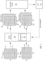
- Figure 1 illustrates a training procedure (or training phase) for a neural network f ⁇ 130 according to an embodiment of the invention.
- the neural network f ⁇ 130 has a plurality of internal, learnable parameters ⁇ 132.
- the training phase of neural network 130 aims at optimizing the parameters of the neural network by training it on a training set of image pairs.
- supervised learning approaches it is necessary to know the expected result for each image pair of the training set (e.g. the corresponding portions of the images of each image pair of the training set are known in terms of binary ground-truth labels for each image pair).
- the present invention relates to an unsupervised learning approach, which in this context refers to learning that does not require any supervision (e.g. in the form of known ground-truth correlations between images).
- the training data set provide pairs of images depicting at least partially the same visual content.
- the training phase starts with an initial set of values for the parameters 132.
- the initial set of values There are several options for choosing the initial set of values. One possibility is to determine the initial set in a preparation step, e.g. by performing an initial training using a state-of-the-art training method for the neural network. Another option is choosing a common value for all parameters ⁇ 132.
- the initial set of values includes a random value for each parameter of the plurality of parameters ⁇ 132.
- the neural network with the initial set of values for the parameters 132 is applied to two different images I 1 110 and I 2 120 of an image pair. Both images of the pair depict at least partially the same visual content (e.g. a same scene, a same object, a same person, or a same architectural structure).
- Image I 1 110 may comprise a pixel grid 112 with height H 1 and width W 1 , including H 1 ⁇ W 1 individual pixels 114.
- Image I 2 120 may comprise a pixel grid 122 with height H 2 and width W 2 including H 2 ⁇ W 2 individual pixels 124.
- pixel grids 112 and 122 may differ from each other because e.g. the images were taken under different lighting conditions, from different camera positions or viewing angles, with different cameras, or using different sensors or lenses.
- the neural network 130 can be described as a function f ⁇ : I ⁇ F I where I denotes an image and F I ⁇ R H ⁇ W ⁇ d is a d-dimensional feature map, which can be viewed as a grid of dense local image descriptors.
- dense in this context denotes a one-to-one relation between the pixels of the image I and the local image descriptors of the grid of image descriptors.
- Feature map 140 comprises a grid of local image descriptors with height H 1 and width W 1 , including H 1 ⁇ W 1 individual local image descriptors 144, wherein each image descriptor 144 corresponds to a pixel 114 in pixel grid 112 and is represented by a d-dimensional vector in R d .
- applying neural network 130 to image I 2 120 generates a feature map F 2 150 from the image.
- Feature map 150 comprises a grid of local image descriptors with height H 2 and width W 2 , including H 2 ⁇ W 2 individual local image descriptors 154, wherein each image descriptor 154 corresponds to a pixel 124 in pixel grid 112 and is represented by a d-dimensional vector in R d .
- a correlation module 160 receives feature maps F 1 140 and F 2 150 and performs a series of steps on the received feature maps to determine loss 170.
- the loss can either be determined from a single image pair or as an average over a plurality of image pairs. In the latter case, the neural network is applied to the images of each of the plurality of image pairs in the same way as described for I 1 and I 2 , thereby generating a respective feature map for each image.
- the correlation module 160 determines an individual loss for each image pair based on the feature maps of the respective images, and from the plurality of individual losses for the individual image pairs, an average loss for the plurality of image pairs. The specific steps performed by correlation module 160 are explained in more detail below with reference to Figure 3 .
- a loss denotes the value of a loss function (also called “cost function”), which is a function that maps an event or values of one or more variables onto a real number representing some "cost” associated with the event.
- cost function also called "cost function”
- the aim of the training phase is to modify the internal, learnable parameters ⁇ 132 of the neural network f ⁇ 130 so that they minimize the loss 170 (i.e. the value of the loss function).
- This optimization of the loss function (which must be convergent towards a minimum) is performed by back-propagation of so called “loss gradients", which are obtained from the partial derivatives of the loss function with respect to the learnable parameters ⁇ 132 of the neural network f ⁇ 130.
- loss gradients are "back-propagated" to the respective learnable parameters ⁇ 132 in that they are used to modify (or adapt or update) the learnable parameters ⁇ 132 of the neural network f ⁇ 130 to produce a lower loss 170 at the next iteration of the training phase.
- the neural network 130 At the next iteration, the neural network 130 generates modified local feature maps F 1 140 and F 2 150, comprising grids of modified local image descriptors for the images I 1 and I 2 , where the feature maps and thereby the local feature descriptors are computed with the modified learnable parameters ⁇ 132.
- modified local feature descriptors are better suited for identifying corresponding portions in images of an image pair, leading to a lower loss 170 and to a smaller adaptation of the learnable parameters ⁇ 132 at the next back-propagation of the loss gradients, until the loss function converges towards a minimum loss 170 and no adaptation of the learnable parameters 132 is necessary anymore.
- neural network 130 Once the loss function has converged, neural network 130 has been successfully trained, and it can then be applied to image pairs for identifying corresponding portions in the images of the image pair.
- Figure 2 illustrates a process of determining corresponding portions of images of an image pair according to an embodiment of the invention.
- a trained neutral network f ⁇ T 230 with a plurality of internal parameters ⁇ T may be the result of a training phase as described with reference to Figure 1 .
- the trained neural network 230 is applied to images 210 and 220 to generate feature map 240 for image 210 and feature map 250 for image 220.
- the process of applying the trained neural network 230 to an image and generating a feature map for the image is equivalent to the respective process in the training phase as described with reference to Figure 1 .
- generated feature maps 240 and 250 each comprise a grid of local image descriptors including a plurality of individual PUMP descriptors corresponding to individual pixels of the image from which the feature map has been generated.
- Feature maps 240 and 250 are subsequently provided to matching module 260, which is configured to extract correspondences 270 between portions of image 210 and image 220 based on the PUMP descriptors of feature maps 240 and 250.
- Each correspondence 270 maps a portion (e.g. a pixel or a patch) of image 210 to a portion (e.g. a pixel or a patch) of image 220.
- a correspondence defines a true match if the corresponding portions of images 210 and 220 depict the same feature of the depicted scene.
- Matching module 260 may implement any suitable technique for determining correspondences 270 for images 210 and 220.
- matching module 260 applies a DeepMatching algorithm ( Revaud et al., "Hierarchical deformable dense matching", IJCV, 2016 ) to feature maps 240 and 250 to extract dense or quasi-dense correspondences 270 between portions of images 210 and 220.
- the DeepMatching algorithm is adapted to the present invention by replacing the basic descriptors of DeepMatching by the PUMP descriptors of feature maps 240 and 250.
- one of images 210 and 220 is split in atomic patches (e.g. in non-overlapping 4x4 pixel patches) and one correspondence 270 is output for each atomic patch.
- matching module 260 applies sparse keypoint-based matching techniques to feature maps 240 and 250 to extract correspondences 270 between keypoints of images 210 and 220.
- These techniques may include SIFT ( Lowe, "Object recognition from local scale invariant features", ICCV, 1999 ), ORB ( Rublee et al., “ORB: an efficient alternative to SIFT or SURF", ICCV, 2011 ), R2D2 ( Revaud et al., “R2D2: repeatable and reliable detector and descriptor", NeurIPS, 2019 ), or SuperPoint ( DeTone et al., "Self-supervised interest point detection and description", CVPR Workshops, 2018 ).
- the applied technique is adapted to the present invention by replacing the basic descriptor of the respective technique with the PUMP descriptors of feature maps 240 and 250.
- FIG. 3 illustrates correlation module 300 for determining a loss during the training phase for neural network 130.
- Correlation module 300 may be an embodiment of correlation module 160 as described with reference to Figure 1 .
- Correlation module 300 receives feature maps F 1 140 and F 2 150, which result from respectively applying neural network 130 to images I 1 and I 2 , as has been previously described with reference to Figure 1 .
- feature map F 1 140 may be sub-sampled 310.
- Sub-sampling 310 refers to a method for reducing the size of feature map F 1 140 by replacing a plurality of entries of feature map 140 by only a single value.
- the grid of local image descriptors 142 of feature map 140 may be partitioned in non-overlapping rectangular atomic portions with a height of n entries (e.g. 2, 3, 4, 5, 6,...) and a width of m entries (e.g. 2, 3, 4, 5, 6,).
- Each portion includes n ⁇ m local image descriptors each of which is described as a d-dimensional vector.
- Sub-sampling 310 replaces the n ⁇ m local image descriptors of each atomic portion by a single local image descriptor for the atomic portion. This is achieved by choosing a single value for each entry of the d-dimensional vector based on the n ⁇ m values of the respective entries in the original local image descriptors of an atomic portion. Any suitable method for choosing a single value from the n ⁇ m original values can be used. In an embodiment, the maximum value of the respective n ⁇ m original values is chosen for each entry of the resulting d-dimensional vector of the local image descriptor.
- the average value of the respective n ⁇ m original values is taken for each entry of the resulting d-dimensional vector of the local image descriptor.
- the vector values of a local image descriptor at a specific position within each portion are chosen to replace the respective n ⁇ m original values.
- an initial 4D correlation volume C 0 320 may be determined based on feature maps F 1 140 and F 2 150.
- initial 4D correlation volume C 0 320 may be determined based on reduced feature map F 1 ' and feature map F 2 150.
- the correlation is denoted as C p , q .
- This correlation is similarly denoted as C p , q .
- reference will only be made to p as a pixel 114 in pixel grid 112 of image 110.
- p ( x p ,y p ) may refer to the center of an atomic portion (or patch) of the pixel grid 112 of image 110.
- Each pixel 114 (or portion) p in pixel grid 112 corresponds to a local feature descriptor 144 D(p) in the grid of local feature descriptors 142 of feature map F 1 140 (or the respective reduced grid of local feature descriptors of reduced feature map F 1 ').
- each pixel 124 q in pixel grid 122 corresponds to a local feature descriptor 154 D(q) in the grid of local feature descriptors 152 of feature map F 2 150.
- Initial correlation volume C 0 320 comprises all possible pixel-pixel correlation values C 0 ( p , q ) .
- the correlation value C 0 ( p,q ) is determined by calculating a similarity value based on D( p ) and D( q ).
- C 0 p q sim D p , D q
- Each similarity value may be a real number representing a measure of similarity between the local image descriptors on D ( p ) and D( q ). Any suitable method for calculating similarity values for a pair of local image descriptors may be used.
- each similarity value is determined as a cosine similarity between the local image descriptors of a pair of local image descriptors on D ( p ) and D( q ) based on the scalar product between the respective d-dimensional vectors representing the local image descriptors.
- each value C 0 ( p,q ) is a number in the range between 0 and 1.
- Initial correlation volume C 0 320 may have dimensions H 1 ⁇ W 1 ⁇ H 2 ⁇ W 2 .
- initial correlation volume C 0 320 may have dimensions H 1 ' ⁇ W 1 ' ⁇ H 2 ⁇ W 2 .
- first-level correlation volume C 1 is determined.
- First-level correlation volume C 1 is comprised of correlation values C 1 ( p , q ), which represent correlations between first-level patches of pixel grid 112 and pixel grid 122.
- a patch is a rectangular portion of a pixel grid (e.g. pixel grid 112 or pixel grid 122).
- patches of width and height 2 (denoted as patch size 2 ⁇ 2), including either 2 ⁇ 2 pixels of a pixel grid or 2 ⁇ 2 patches of the previous iteration step.
- patch size 2 ⁇ 2 is not to be construed as limiting to the present invention, and other patch sizes (e.g. 2 ⁇ 3, 3 ⁇ 2, 3 ⁇ 3, or 4 ⁇ 4) may be utilized in embodiments of the present invention.
- 0-level patches are considered to be pixels of the respective pixel grids.
- an l-level patch has 2 ⁇ 2 children patches of level l - 1 for 1 ⁇ l ⁇ L.
- the correlation between l-level patches is determined based on the pair-wise correlations between the (l - 1)-level patches of which the l-level patches are comprised.
- C l ( p,q ) may be computed as the average correlation of its four (l-1)-level child patches in C l-1 :
- C l p q 1 4 C l ⁇ 1 p + v 0 l ⁇ 1 , q + v 0 l ⁇ 1 + C l ⁇ 1 p + v 1 l ⁇ 1 , q ⁇ v 1 l ⁇ 1 + C l ⁇ 1 p ⁇ v 2 l ⁇ 1 , q + v 2 l ⁇ 1 + C l ⁇ 1 p + v 3 l ⁇ 1 , q + v 3 l ⁇ 1
- Aggregation step 334 can be implemented using 4D convolutions with a fixed sparse kernel, where non-zero values encode the parent-children relations in the pyramid. So far, this formulation is able to handle rigid transformations, where all child patches strictly fit into the boundaries of the parent patch.
- Some embodiments include an extension of the aggregation procedure, which allows for a certain degree of local deformations.
- small local deformations of child patches may be taken into account at each iteration level by an additional 2D max-pooling step 332 performed before 4D Aggregation step 334 in each iteration cycle.
- the 2D max-pooling is performed with a suitable kernel (e.g. of size 3 ⁇ 3) along both dimensions of pixel grid 122 of the second Image I 2 120.
- ⁇ i denotes a small local neighborhood centered at q i l ⁇ 1 .
- the number of (l - 1)-level patches in the neighborhood ⁇ i of q i l ⁇ 1 is denoted
- the width and the height of the neighborhood ⁇ i is a predetermined fraction (e.g. 1 4 , 1 2 , 1 ) of the width and the height of the child (l - 1)-level patches.
- Rectification step 336 can optionally be performed to strengthen consistent correlations and discard spurious ones.
- Rectification step 336 may be implemented as a power non-linearity x ⁇ max(0, x ⁇ ) applied at the end of each iteration step to the output correlation values of 4D aggregation step 334.
- Figure 4 illustrates the deformable pyramidal structure, which is enforced by iterative pyramid construction 330.
- the figure shows patches at three levels of iterative pyramid construction 330. At level l + 2, four neighboring (l + 2)-level patches 412, 414, 416 and 418 are shown.
- a correlation in the parent level correlation volume C l +2 aggregates four correlations of the child level with a small tolerance for deformations, and so on for all levels.
- An (l + 2)-level correlation for (l + 2)-level patch 412 is aggregated from (l + 1)-level correlations for (l + 1)-level patches 422, 424, 426 and 428.
- an (l + 1)-level correlation for (l + 1)-level patch 422 is aggregated from l-level correlations for l-level patches 432, 434, 436 and 438.
- C L 340 the output of the iterative pyramid construction applied to C 0 320 is consolidated high-level correlation volume C L 340.
- the third and fourth dimensions of C L 340 which correspond to the dimensions of the pixel grid 122 of I 2 120, are reduced by a factor 2 L , where L is the number of iterations (or pyramid levels) of iterative pyramid construction 330.
- the reduction factor may be different for other choices of the patch size in iterative pyramidal construction 330 and is not to be construed as limiting for the present invention.
- C L 340 may have dimensions H 1 ⁇ W 1 ⁇ H 2 ⁇ W 2 . If optional sub-sampling step 310 is performed, C L 340 may have dimensions H 1 ' ⁇ W 1 ' ⁇ H 2 ⁇ W 2 .
- the consolidated high-level correlation volume C L represents the correlations between large deformable high-level patches.
- a high-level patch centered at pixel p has a unique match in image I 2 , i.e., there should exist only one q such that C L ( p ,q) has a high value, while all other correlations for q' ⁇ q will be close to 0. While this constraint is not realistic for pixel-level descriptors due to repetitive patterns, plain regions without structure, or severe appearance changes, it appears as a natural property for high-level patches in C L 340. In fact, the larger a patch is, the easier it is to resolve ambiguities and hard correspondences due to the larger context.
- uniqueness matching loss 350 is determined from C L 340 that encourages the property of a unique match for every high-level patch.
- Uniqueness matching loss 350 is the output value of correlation module 300 and represents an embodiment of loss 170 as illustrated in Figure 1 . Since each high-level patch is dynamically built at test-time upon a deformable subset of pixel-level correlations, this loss is automatically back-propagated to optimal pixel correlations fitting iterative pyramid construction 330, and hence to pixel level local image descriptors.
- C L may be formally reshaped as a 2-dimensional tensor of size W 1 H 1 ⁇ W 2 H 2 4 L (or in case sub-sampling step 310 is performed of size W 1 ′ H 1 ′ ⁇ W 2 H 2 4 L ).
- ⁇ serves as a regularization term that deals with occluded areas, for which all correlations would be close to zero.
- the value of ⁇ can be adapted to the circumstances and is not to be construed as limiting to the present invention. In an embodiment, the value of ⁇ is 0.03.
- H 1 ⁇ W 1 in equation (5) is replaced by H 1 ' ⁇ W 1 ' in case optional sub-sampling step 310 is performed to generate reduced feature map F 1 '.
- C L is l 1 -normalized, the uniqueness loss concretely encourages all values in C L to be close to 0 except one per row (i.e. one per high-level patch) that will be close to 1.
- the computational cost and memory footprint may be reduced in embodiments, by additionally sub-sampling feature maps F 1 and F 2 by a predetermined factor (e.g. by a factor 2) before passing them to correlation module 300.
- the model is trained with batches of image pairs (e.g. 10 image pairs, 12 image pairs, 16 image pairs, or 24 image pairs). A portion of the image pairs of the batch (e.g. half of the image pairs, 2/3 of the image pairs, a quarter or three quarters of the image pairs) are trained with unsupervised loss 350 (e.g.
- An averaged unsupervised loss L U ⁇ may be calculated over all image pairs of the portion of the batch of image pairs.
- the remaining portion of the batch of image pairs is generated synthetically via standard data augmentation of single images in a self-supervised manner.
- a pixel-wise ranking loss L P e.g. average precision loss L AP as in Revaud et al., "R2D2: repeatable and reliable detector and descriptor", NeurIPS, 2019 and US Patent 11176425 B2 ) is used, which is based on the extracted feature maps for each image in an image pair and the known ground-truth correspondences.
- An average loss L P ⁇ may be determined over all image pairs of the remaining portion of the batch of image pairs.
- the final loss L may then be calculated as a weighted sum of the averaged losses.
- L is calculated as L AP ⁇ + 0.3 L ′ U ⁇ .
- a suitable number of training iterations e.g. 50000 have to be performed in order to achieve convergence for f ⁇ .
- the fixed learning rate of 10 -4 and a weight decay of 5.10 -4 is used for performing the training.
- FIG. 5 is a functional block diagram illustrating a computer-implemented method 500 of unsupervised neural network training for learning of local image descriptors, according to an embodiment.
- the method is implemented as a training phase for a neural network (e.g. neural network 130) as illustrated in Figures 1 and 3 .
- the method starts at step 510, at which a pair of training images is obtained.
- Obtaining the training images encompasses that they can be received from any memory location (e.g. a local or remote computing system, a local or remote database, a cloud storage or any other memory location known in the field) on which they are stored. Alternatively, the images may be automatically retrieved from any of these memory locations.
- the images of the obtained image pair depict a same scene or visual content (e.g.
- the obtained image pair includes a first image (e.g. image 110) with a first pixel grid (e.g. pixel grid 112) and a second image (e.g. image 120) with a second pixel grid (e.g. pixel grid 122).
- the pixel grids differ in at least one aspect.
- the first pixel grid may have different horizontal and/or vertical dimensions different from those of the second pixel grid. Additionally or alternatively, the pixel values of at least a portion of the pixels in the first pixel grid may differ from pixel values of the respective pixels in the second pixel grid.
- the neural network is applied to the first image to generate a feature map F 1 (e.g. feature map 140). Additionally, the neural network is applied to the second image to generate a feature map F 2 (e.g. feature map 150).
- the neural network has an initial set of internal, learnable parameters (e.g. parameters 132).
- Feature map F 1 comprises a first grid of local descriptors (e.g. grid of local descriptors 142), wherein each local descriptor (e.g. local descriptor 144) in the first grid of local descriptors corresponds to a pixel within the first pixel grid.
- Each local descriptor of the first grid of local descriptors is a computer-processable description of the local environment of the corresponding pixel in the first pixel grid.
- Feature map F 2 comprises a second grid of local descriptors (e.g. grid of local descriptors 152), wherein each local descriptor (e.g. local descriptor 154) in the second grid of local descriptors corresponds to a pixel within the second pixel grid.
- Each local descriptor of the second grid of local descriptors is a computer-processable description of the local environment of the corresponding pixel in the second pixel grid.
- a local image descriptor may be represented as a d-dimensional vector and is extracted from a pixel grid through the application of the neural network on the respective image.
- an initial correlation volume C 0 (e.g. initial correlation volume 320) is determined based on F 1 and F 2 .
- Initial correlation volume C 0 comprises local correlations of pixels of the first pixel grid with pixels of the second pixel grid. Each local correlation is determined for a pixel of the first pixel grid and a pixel of the second pixel grid based on a first corresponding local image descriptor in the and first grid of local image descriptors and a second corresponding local image descriptor in the second grid of local image descriptors.
- the first corresponding local image descriptor corresponds to the pixel in the first pixel grid and the second corresponding local image descriptor corresponds to the pixel in the second pixel grid.
- the correlation C 0 ( p , q ) between a pixel p of the first pixel grid and a pixel q of the second pixel grid is determined as a similarity between local image descriptors D( p ) and D( q ).
- D( p ) corresponds to p and is comprised in the first grid of local image descriptors.
- D( q ) corresponds to q and is in comprised the second grid of local image descriptors.
- the similarity between local image descriptors D( p ) and D( q ) may be determined as a cosine similarity based on the scalar product of the d-dimensional vectors representing D( p ) and D( q ).
- a high-level correlation volume C L (e.g. high-level correlation volume 340) is determined based on C 0 by iterative pyramid construction (e.g. iterative pyramid construction 330).
- High-level correlation volume C L comprises aggregated high-level correlations between iteratively constructed high-level patches of the first and second pixel grids.
- Each high-level patch of the first pixel grid is a rectangular portion of the first pixel grid.
- Each high-level patch of the second pixel grid is a rectangular portion of the second pixel grid.
- C L may be iteratively constructed starting from C 0 .
- a first iteration step may comprise aggregating local correlations of C 0 to first-level correlations between first-level patches of the first pixel grid and first-level patches of the second pixel grid, thereby generating a first-level correlation volume C 1 .
- the first-level correlation between a first-level patch of the first pixel grid and a first-level patch of the second pixel grid may be determined as an averaged sum of local correlations between corresponding pixels in the first-level patch of the first pixel grid and the first-level patch of the second pixel grid.
- Each of the local correlations in the averaged sum of local correlations may have a maximum correlation value among a plurality of neighboring local correlation values.
- a subsequent ( n + 1) th iteration step for 1 ⁇ n ⁇ L may comprise generating an ( n + 1)-level correlation volume C n +1 by aggregating n -level correlations of C n to ( n + 1)-level correlations between ( n + 1)-level patches of the first pixel grid and ( n + 1)-level patches of the second pixel grid.
- the ( n + 1)-level patches may be comprised of neighboring n -level patches of the respective pixel grid.
- the aggregated n -level correlations correspond to the neighboring n -level patches of the correlated ( n + 1)-level patches.
- the ( n + 1)-level correlation between an ( n + 1)-level patch of the first pixel grid and an ( n + 1)-level patch of the second pixel grid may be determined as an averaged sum of n -level correlations between corresponding n -level patches of the ( n + 1)-level patch of the first pixel grid and the ( n + 1)-level patch of the second pixel grid.
- Each of the n-level correlations in the averaged sum of n-level correlations may have a maximum correlation value among a plurality of neighboring n-level correlation values.
- a uniqueness matching loss (e.g. uniqueness matching loss 350) is determined for F 1 and F 2 based on C L .
- the uniqueness matching loss provides a measure for a deviation of F 1 and F 2 from optimal feature maps.
- the uniqueness matching loss is configured to indicate a low deviation to optimal feature maps if, based on the high-level correlations in C L , each high-level patch of the first pixel grid has a unique (i.e. only one) match among the high-level patches of the second pixel grid and each high-level patch of the second pixel grid has a unique (i.e. only one) match among the high-level patches of the first pixel grid.
- the uniqueness matching loss has low values if for each high-level patch of the first and the second pixel grids only one high-level correlation in C L corresponding to the respective patch has a high correlation value and all other high-level correlations in C L corresponding to the respective high-level patch have a low correlation value.
- a high correlation value may be close to 1, whereas a low correlation value may be close to 0.
- the neural network is trained by minimizing a loss function based on the uniqueness matching loss to generate an optimized set of parameters.
- Minimizing the loss function may include performing backpropagation based on the loss function to determine a new set of parameters which achieves a lower uniqueness matching loss in a subsequent training step.
- Training the network may further include repeating the steps of the method with the optimized set of parameters for a predetermined number of times or until the optimized set of parameters converges, thereby generating a trained neural network adapted for determining local image descriptors.
- Figure 6 is a functional block diagram illustrating computer-implemented method 600 of determining corresponding portions in images with a trained neural network according to an embodiment, wherein the neural network has been trained according to the method illustrated in Figure 5 .
- the method starts at step 610 where the trained neural network is applied to first new image (e.g. image 210) to generate a first feature map (e.g. feature map 240) comprising a first grid of local image descriptors.
- the trained neural network is applied to a second new image (e.g. image 220) to generate a second feature map (e.g. feature map 250) comprising a second grid of local image descriptors.
- the first and second new images may depict a same scene using different pixel grids.
- a correspondence (e.g. one of correspondences 270) between a portion of the first new image and a portion of the second new image is identified based on the first and second grids of local image descriptors.
- the corresponding portions identified relate to a same part of the depicted scene. Additional correspondences between the images may be determined either between keypoints of the images or for each pixel in the images (i.e. dense correspondences).
- Step 630 may be performed by matching module 260 shown in Figure 2 .
- HPatches ( Balnats et al., "A Benchmark and evaluation of handcrafted and learned local descriptors", CVPR, 2017 ) consists of 116 image sequences with varying photometric and viewpoint changes. Each sequence contains a reference image and five source images related by a homography to the source image taken under different viewpoint or illumination.
- ETH3D ( Schöps et al., "A multi-view stereo benchmark ) contains indoor and outdoor sequences captured using a hand-held camera and registered with SfM. Image pairs are generated by sampling frames with a fixed interval. It is used to evaluate the robustness to viewpoint changes as the baseline widens for increasing intervals.
- Aachen Day-Night v1.1 ( Zhang et al., "Reference pose generation for long-term visual localization via learned features and view synthesis", IJCV, 2021 ) is a large-scale outdoor visual localization benchmark.
- the Day-Night split is specifically considered to measure the generalization performance of the embodiments of the present invention, as it features large viewpoint changes and severe illumination changes due to the day/night duality.
- the following method is used: in a first step, a global SfM map is built from the database images, and in a second step, query images are localized with regard to this mapping.
- the performance of the PUMP descriptors is evaluated in a dense or quasi-dense manner using DeepMatching ( Revaud et al., "DeepMatching: Hierarchical deformable dense matching", IJCV, 2016 ).
- DeepMatching Revaud et al., "DeepMatching: Hierarchical deformable dense matching", IJCV, 2016 .
- the basic pixel descriptor of DeepMatching is replaced by the PUMP descriptors.
- the rest of the pipeline is left unchanged, except for the built-in cycle-consistency verification that has been enhanced to include nearest neighbors as well.
- DeepMatching is not dense but quasi-dense, as it outputs one correspondence per atomic patch from the first image.
- a densification technique is used following COTR's scheme ( Jiang et al., "Cotr: Correspondence transformer for matching across images", ICCV, 2021 ) which includes linearly interpolate matches using a Delaunay triangulation.
- Table 1 represents both quasi-dense and fully-dense (i.e. interpolated) outputs.
- Two models according to embodiments of the present invention are evaluated: one trained solely from self-supervised pairs (S), i.e., obtained via data augmentation, and one including unsupervised pairs as well (S+U). Without interpolation, the self-supervised model (S) performs slightly better than the model trained with unsupervised pairs (S+U). This is not surprising given that it is trained exclusively from synthetic augmentations (homographies) fitting exactly the distribution of the test set.
- the unsupervised model (S+U) outperforms the self-supervised model (S), indicating that the unsupervised loss allows for production of fewer outliers (as these strongly impair Delaunay interpolation) and is thus more robust.
- both models outperform all state-of-the-art approaches by a large margin.
- Both models according to embodiments of the present invention also significantly outperform the recently proposed unsupervised WarpC matching loss ( Truong et al.,"Warp consistency of unsupervised learning of dense correspondences", ICCV, 2021 ). Altogether, these results highlight the excellent capacity of our pyramidal matching prior according to embodiments of the present invention in the case of large planar areas without discontinuities.
- Embodiments of the present invention are evaluated in a more challenging setting with real image pairs from ETH3D featuring viewpoint changes on complex 3D shapes and many discontinuities in the optical flow. Since the ground-truth is sparse and not necessarily aligned with the quasi-dense output, only results with the densely-interpolated variant for various frame intervals (e.g. rate) are presented in Table 2. It is observed that the model trained with unsupervised pairs significantly outperforms the self-supervised one by up to 25% (relative gain). This highlights the superior robustness against realistic noise of the model trained by injecting matching priors. Overall, it also outperforms all existing approaches, scoring the first or second Average End Point Error (AEPE) for all rate intervals.
- AEPE Average End Point Error
- the models according to embodiments are significantly faster than other methods such as DPM ( Hong and Kim, “Deep matching prior: Test-time optimization for dense correspondence", ICCV, 2021 ), which requires multiple minutes per testing pair for specific fine-tuning on each one.
- the performance for three standard detectors is measured: SIFT ( Lowe, “Object recognition from local scale invariant features", ICCV, 1999 ), R2D2 ( Revaud et al., “R2D2: repeatable and reliable detector and descriptor", NeurIPS, 2019 ) and SuperPoint ( DeTone et al.: “Self-supervised interest point detection and description", CVPR Workshops, 2018 ).
- SIFT Lowe, "Object recognition from local scale invariant features", ICCV, 1999
- R2D2 Revaud et al., “R2D2: repeatable and reliable detector and descriptor", NeurIPS, 2019
- SuperPoint DeTone et al.: “Self-supervised interest point detection and description", CVPR Workshops, 2018 ).
- the same number of keypoints are extracted at the same locations and scales for each method, making the evaluation fair and strictly centered on the descriptors.
- MMA Mean Matching Accuracy
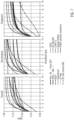
- Figure 7 illustrates a comparison of the performance of models according to the present invention with the state of the art on HPatches (in this case R2D2's keypoint detector is used to extract the keypoints).
- the figure shows matching results on the HPatches dataset in terms of Mean Matching Accuracy (MMA) for various error thresholds.
- the models according to embodiments of the invention significantly outperform all state-of-the-art methods, including the recent Sparse NCNet ( Rocco et al., "Neighbourhood consensus network", NeurIPS, 2018 ) and the self-supervised method CAPS-U ( Melekhov et al., "Digging into self-supervised learning of feature descriptors", 3DV, 2021 ).
- Some or all of the method steps may be implemented by a computer in that they are executed by (or using) a processor, a microprocessor, an electronic circuit or processing circuitry.
- the embodiments described above may be implemented in hardware or in software.
- the implementation can be performed using a non-transitory storage medium such as a computer-readable storage medium, for example a floppy disc, a DVD, a Blu-Ray, a CD, a ROM, a PROM, an EPROM, an EEPROM or a FLASH memory.
- a computer-readable storage medium for example a floppy disc, a DVD, a Blu-Ray, a CD, a ROM, a PROM, an EPROM, an EEPROM or a FLASH memory.
- Such computer-readable media can be any available media that can be accessed by a general-purpose or special-purpose computer system.
- embodiments can be implemented as a computer program product with a program code or computer-executable instructions, the program code or computer-executable instructions being operative for performing one of the methods when the computer program product runs on a computer.
- the program code or the computer-executable instructions may, for example, be stored on a computer-readable storage medium.
- a storage medium (or a data carrier, or a computer-readable medium) comprises, stored thereon, the computer program or the computer-executable instructions for performing one of the methods described herein when it is performed by a processor.
- an apparatus comprises one or more processors and the storage medium mentioned above.
- a system comprises means, for example processing circuitry such as a processor communicating with a memory, the means being configured to, or adapted to, perform one of the methods described herein.
- a further embodiment comprises a computer having installed thereon the computer program or instructions for performing one of the methods described herein.
- FIG. 8 The above-mentioned methods and embodiments may be implemented within a system architecture such as illustrated in Figure 8 , which comprises server 800 and one or more client devices 802 that communicate over a network 804 (which may be wireless and/or wired), such as the Internet, for data exchange.
- Server 800 and the client devices 802 include a data processor 812 and memory 813 such as a hard disk.
- the client devices 802 may be any device that communicates with server 800, including autonomous vehicle 802b, robot 802c, computer 802d, or cell phone 802e.
- the method 500 for unsupervised neural network training for learning of local image descriptors is performed at server 800.
- the server may provide the trained neural network (e.g. trained neural network 230) to any of the devices, which may then perform method 600 based on the received trained neural network to compute optimal local image descriptors for determining whether a true match exists between image pairs.
- the determination that a true match exists is used in different applications including, visual localization and mapping, pose estimation, Structure-from-Motion, 3D reconstruction, and image search that rely on such descriptors.
- one of the devices 802 performs both methods 500 and 600.
- autonomous vehicle 802b (or robot 802c) comprises an optical sensor which obtains a first image of the surroundings of the vehicle (or the robot).
- the vehicle (or the robot) stores a second image (with location information) of the surroundings of the vehicle (or the robot) on memory device 813b/c.
- Vehicle 802b (or robot 802c) then performs method 600 with the first and second image to identify corresponding portions in the images to determine a position of the vehicle (or the robot) within the surroundings of the vehicle (or the robot) via visual localization.
Landscapes
- Engineering & Computer Science (AREA)
- Theoretical Computer Science (AREA)
- Physics & Mathematics (AREA)
- General Physics & Mathematics (AREA)
- Computer Vision & Pattern Recognition (AREA)
- Evolutionary Computation (AREA)
- Multimedia (AREA)
- General Health & Medical Sciences (AREA)
- Artificial Intelligence (AREA)
- Health & Medical Sciences (AREA)
- Software Systems (AREA)
- Computing Systems (AREA)
- Databases & Information Systems (AREA)
- Medical Informatics (AREA)
- Life Sciences & Earth Sciences (AREA)
- Biomedical Technology (AREA)
- Molecular Biology (AREA)
- Biophysics (AREA)
- Computational Linguistics (AREA)
- Data Mining & Analysis (AREA)
- General Engineering & Computer Science (AREA)
- Mathematical Physics (AREA)
- Biodiversity & Conservation Biology (AREA)
- Image Analysis (AREA)
Abstract
Description
- The present disclosure relates to a neural network for image analysis, in particular, to a system, method and computer-readable medium for unsupervised learning of the neural network for computing local image descriptors for determining whether a pair of images depict the same scene, and applications therefor.
- One of the persistent challenges of computer-based image analysis is the identification of corresponding pixels or portions of two images. This image analysis problem is central to numerous computer vision tasks, such as large-scale visual localization, object detection, pose estimation, Structure-from-Motion (SfM), 3D reconstruction and Simultaneous Localization and Mapping (SLAM). In all these tasks, it is necessary to identify corresponding portions of two images depicting at least partially the same visual content. Two different images representing the same visual content can differ in a wide range of parameters, such as the viewing angle of the depicted motif, position of the motif within the image frame, the camera, lens and sensor type used to capture the image, lighting and weather conditions, focal length, and/or sharpness, to name just a few. While a human can, even for images that differ markedly from each other, easily identify image parts that show the same feature of a depicted object or person, this task is actually rather complex due to severe differences in geometry, color and contrast between the images. Solving this problem with computer-based systems is an ongoing subject of research in the field of artificial intelligence.
- An important component of many approaches to addressing the issue of identifying correspondences between images are local image descriptors (also called pixel descriptors), which are extracted from an image. A local image descriptor characterizes a neighborhood of a pixel of the image and provides a computer-processable data structure that enables a computing system to compare local environments of pixels by determining correlations between pixels based on their local image descriptors. Local image descriptors can be extracted from an image sparsely (i.e. only for selected keypoints of the image) or densely (i.e. for each pixel of the image). The process of extracting (i.e. computing) local image descriptors from an image is crucial for the quality of the identified correspondences. Existing learning-based approaches for extracting local image descriptors significantly outperform standard handcrafted methods such as SIFT (Lowe, "Object recognition from local scale invariant features", ICCV, 1999) or ORB (Rublee et al., "ORB: an efficient alternative to SIFT or SURF", ICCV, 2011). Learning-based approaches are often based on training procedures relying on the existence of annotated training data sets that include a large number of image pairs for which pixel-level correspondences (i.e. dense ground-truth correspondences) are known. These correspondences are usually obtained by considering a large collection of images for a given landmark and building a Structure-from-Motion reconstruction (Li and Snavely, "Megadepth: Learning single view depth prediction from internet photos", CVPR, 2018). This pipeline fails in many cases, yielding an unfathomable bottleneck to the kind of ground-truth data that can be generated. This limits the enormous potential of available image data to only those image pairs for which ground-truth labels can be efficiently derived. Since limited training data sets have a direct negative impact on the training results, it would be beneficial to overcome these restrictions in order to fully exploit the potential of available image pairs as training data sets.
- A first step to the solution of this problem is provided by pure self-supervised learning approaches, which still rely on ground-truth labeled correspondences between images but can generate those correspondences as part of the approach with limited effort. Purely self-supervised learning approaches use synthetically generated image pairs in the training phase, where the second image is obtained by applying known transformations to the first image, such as a random homography, color jittering or even style transfer. However, homographies and the like cannot model the full range of possible transformations between real image pairs. In parallel, weakly-supervised methods have been proposed that demonstrate the ability to train from, for example, known camera poses (Wang et al., "Learning feature descriptors using camera pose supervision", ECCV, 2020). However, this is only achievable through the use of complex acquisition setups that require the deployment of sensors based on different modalities (IMU or GPS), or again, resort to SfM reconstructions. Recently, unsupervised learning of local descriptors has been introduced in the form of cycle consistency constraints across multiple images (Truong et al., "Warp consistency of unsupervised learning of dense correspondences", ICCV, 2021; and Zhou et a/., "Joint image set alignment by weaving consistent, pixel-wise correspondences, CPVR, 2015), either requiring extraction of features on more images for training, or costly iterative training of descriptors and expensive model fitting (Yang et al., "MONET: multiview semi-supervised keypoint detection via epipolar divergence, ICCV, 2019).
- In order to overcome the above deficiencies, a computer-implemented method for learning local descriptors without supervision is presented. The approach of the method is to jointly enforce two matching priors: local consistency and uniqueness of the matching. The former is based on the observation that two neighboring pixels of one image will likely match with two pixels forming a similar neighboring pair in the other image, up to a small deformation. It is assumed that this generally holds true at any scale. In disclosed embodiments, this prior is efficiently enforced through a pyramidal structure. A pyramidal non-parametric module extracts higher-level correspondences, enforcing the local consistency matching prior by design. The uniqueness prior is based on the observation that one pixel from the first image can correspond to at most one pixel in the second image. This property is enforced on high-level correspondences via a uniqueness matching loss. It is naturally propagated to low-level pixel correspondences, thanks to the pyramidal hierarchical structure. As a result, the combination of a local consistency prior and a uniqueness prior enables an effective learning of local image descriptors without supervision.
- The resulting training method of a neural network for determining local image descriptors does not require any supervision, e.g. in the form of ground-truth correspondences between training images. The trained neural network is adapted to extract optimal local image descriptors. Extracted optimal local image descriptors (also referred to as PUMP descriptors) are configured to identify correspondences between portions of different images, including scenes depicting the same visual content but having differing image parameters, for example, a pair of images of the same scene that differ in viewpoint or lighting conditions.
- In an embodiment, a computer-implemented method of unsupervised neural network training for learning of local image descriptors is provided. The method comprises the steps of: obtaining a pair of images depicting a same scene, the pair of images including a first image with a first pixel grid and a second image with a second pixel grid, wherein the first pixel grid differs from the second pixel grid; applying a neural network having an initial set of parameters to the first image and the second image to generate a feature map F 1 for the first image and a feature map F 2 for the second image, F 1 comprising a first grid of local image descriptors and F 2 comprising a second grid of local image descriptors, wherein each local image descriptor in the first grid of local image descriptors corresponds to a respective pixel within the first pixel grid and each local image descriptor in the second grid of local image descriptors corresponds to a respective pixel within the second pixel grid; determining an initial correlation volume C 0 based on F 1 and F 2, wherein C 0 comprises local correlations of pixels of the first pixel grid with pixels of the second pixel grid, wherein each local correlation between a pixel of the first pixel grid and a pixel of the second pixel grid is determined based on the local image descriptors corresponding to the correlated pixels; determining a high-level correlation volume CL based on C 0 by iterative pyramid construction, wherein CL comprises aggregated high-level correlations between iteratively constructed high-level patches of the first and second pixel grids, each patch being a rectangular portion of the respective pixel grid; determining a uniqueness matching loss for F 1 and F 2 based on CL , the uniqueness matching loss providing a measure for a deviation of F 1 and F 2 from optimal feature maps, wherein the deviation from optimal feature maps is low if, based on the high-level correlations in CL , each high-level patch of the first and the second pixel grids has a unique match among the high-level patches of the respective other pixel grid; and training the neural network by minimizing a loss function based on the uniqueness matching loss to generate an optimized set of parameters, thereby generating a trained neural network for determining optimal local image descriptors.
- In another embodiment, a computer-implemented method for identifying correspondences between a pair of input images is provided. The method comprises: receiving the input image pair including a first input image and a second input image; processing the input image pair with the trained neural network for determining optimal local image descriptors, the trained neural network generating local image descriptors for the input image pair described above; extracting correspondences between portions of the input image pair based on the image descriptors, each extracted correspondence mapping a portion of the first input image to a portion of the second input image; determining with the extracted correspondences whether a true match exists between the input image pair, a true match existing between the input image pair when corresponding portions of the image pair depict a same scene; and outputting whether a true match exists between the image pair.
- In yet another embodiment, a system comprising a processing unit and a memory connected to the processing unit is provided. The memory comprises computer-executable instructions that, when executed by the processing unit, cause the processing unit to perform the computer-implemented method of unsupervised neural network training for learning of local image descriptors or the computer-implemented method for identifying correspondences between a pair of input images described above.
- According to a further embodiment, one or more computer-readable media having computer-readable instructions stored thereon are provided. When executed by a processing unit, the computer-readable instructions cause the processing unit to perform the method of unsupervised neural network training for learning of local image descriptors or the computer-implemented method for identifying correspondences between a pair of input images described above.
- The accompanying drawings are incorporated into and form a part of the specification for the purpose of explaining the principles of the embodiments. The drawings are not to be construed as limiting the embodiments to only those illustrated therein. Further features and advantages will become apparent from the following and more particularly from the description of the embodiments, as illustrated in the accompanying drawings, wherein:
-
Figure 1 illustrates a procedure for training a neural network for determining correspondences between images of an image pair according to an embodiment of the invention. -
Figure 2 illustrates a procedure for determining correspondences between images of an image pair by applying a trained neural network to the images according to an embodiment of the invention. -
Figure 3 illustrates the correlation module ofFigure 1 according to an embodiment of the invention. -
Figure 4 illustrates the construction of higher-level image patches from lower-level image patches in the iterative pyramid construction ofFigure 3 according to an embodiment of the invention. -
Figure 5 is a functional block diagram illustrating a method of training a neural network according to an embodiment of the invention. -
Figure 6 is a functional block diagram illustrating a method for determining correspondences between images of an image pair according to an embodiment of the invention. -
Figure 7 is a series of graphs showing a comparison of experimental sparse matching evaluation results on the HPatches data set for a number of different state-of-the-art techniques with an implementation of the present invention. -
Figure 8 illustrates an example system architecture in which the disclosed methods may be performed. - Described herein are systems and methods for unsupervised neural network training for learning of local image descriptors. For purposes of explanation, numerous examples and specific details are set forth in order to provide a thorough understanding of the described embodiments. Embodiments as defined by the claims may include some or all of the features in these examples alone or in combination with otherfeatures described below, and may further include modifications and equivalents of the features and concepts described herein. The illustrative embodiments will be described with reference to the drawings, wherein like elements and structures are indicated by like reference numbers.
- The present invention relates to a method, a system and a computer-readable medium for unsupervised neural network training for learning of image descriptors that are adapted for the determination of corresponding portions in images showing the same visual content. The present invention achieves unsupervised neural network training for learning of image descriptors by configuring a neural network such that the neural network, when applied to a given image I of dimension H × W, extracts a highly discriminative yet robust local image descriptor for each pixel of I. In order to obtain a neural network able to extract such local image descriptors, the neural network must first be "trained". Local image descriptors extracted from an image by a neural network trained according to embodiments of the invention are denoted PUMP descriptors (PUMP: Pyramidal and Uniqueness matching Priors).
-
Figure 1 illustrates a training procedure (or training phase) for aneural network f θ 130 according to an embodiment of the invention. Theneural network f θ 130 has a plurality of internal, learnable parameters θ 132. The training phase ofneural network 130 aims at optimizing the parameters of the neural network by training it on a training set of image pairs. In supervised learning approaches, it is necessary to know the expected result for each image pair of the training set (e.g. the corresponding portions of the images of each image pair of the training set are known in terms of binary ground-truth labels for each image pair). However, the present invention relates to an unsupervised learning approach, which in this context refers to learning that does not require any supervision (e.g. in the form of known ground-truth correlations between images). The only condition which has to be met by a training data set suitable for unsupervised learning according to embodiments of the present invention is that the training data set provide pairs of images depicting at least partially the same visual content. The training phase starts with an initial set of values for theparameters 132. There are several options for choosing the initial set of values. One possibility is to determine the initial set in a preparation step, e.g. by performing an initial training using a state-of-the-art training method for the neural network. Another option is choosing a common value for all parameters θ 132. In a specific embodiment, the initial set of values includes a random value for each parameter of the plurality of parameters θ 132. - In a first step the neural network with the initial set of values for the
parameters 132 is applied to two different images I 1 110 and I 2 120 of an image pair. Both images of the pair depict at least partially the same visual content (e.g. a same scene, a same object, a same person, or a same architectural structure). Image I 1 110 may comprise apixel grid 112 with height H 1 and width W 1, including H 1 × W 1individual pixels 114. Image I 2 120 may comprise apixel grid 122 with height H 2 and width W 2 including H 2×W 2individual pixels 124. Although both images depict the same visual content,pixel grids - Mathematically, the
neural network 130 can be described as a function fθ : I → FI where I denotes an image and
- Accordingly, applying
neural network 130 to image I 1 110 generates or extracts afeature map F 1 140 from the image.Feature map 140 comprises a grid of local image descriptors with height H 1 and width W 1, including H 1 × W 1 individuallocal image descriptors 144, wherein eachimage descriptor 144 corresponds to apixel 114 inpixel grid 112 and is represented by a d-dimensional vector in
neural network 130 to image I 2 120 generates afeature map F 2 150 from the image.Feature map 150 comprises a grid of local image descriptors with height H 2 and width W 2, including H 2 × W2 individuallocal image descriptors 154, wherein eachimage descriptor 154 corresponds to apixel 124 inpixel grid 112 and is represented by a d-dimensional vector in
- A
correlation module 160 receives feature mapsF 1 140 andF 2 150 and performs a series of steps on the received feature maps to determineloss 170. The loss can either be determined from a single image pair or as an average over a plurality of image pairs. In the latter case, the neural network is applied to the images of each of the plurality of image pairs in the same way as described for I 1 and I 2, thereby generating a respective feature map for each image. Thecorrelation module 160 determines an individual loss for each image pair based on the feature maps of the respective images, and from the plurality of individual losses for the individual image pairs, an average loss for the plurality of image pairs. The specific steps performed bycorrelation module 160 are explained in more detail below with reference toFigure 3 . - In machine learning, a loss denotes the value of a loss function (also called "cost function"), which is a function that maps an event or values of one or more variables onto a real number representing some "cost" associated with the event. The aim of the training phase is to modify the internal, learnable parameters θ 132 of the
neural network f θ 130 so that they minimize the loss 170 (i.e. the value of the loss function). This optimization of the loss function (which must be convergent towards a minimum) is performed by back-propagation of so called "loss gradients", which are obtained from the partial derivatives of the loss function with respect to the learnable parameters θ 132 of theneural network f θ 130. These loss gradients are "back-propagated" to the respective learnable parameters θ 132 in that they are used to modify (or adapt or update) the learnable parameters θ 132 of theneural network f θ 130 to produce alower loss 170 at the next iteration of the training phase. - At the next iteration, the
neural network 130 generates modified local feature mapsF 1 140 andF 2 150, comprising grids of modified local image descriptors for the images I1 and I 2, where the feature maps and thereby the local feature descriptors are computed with the modified learnable parameters θ 132. These modified local feature descriptors are better suited for identifying corresponding portions in images of an image pair, leading to alower loss 170 and to a smaller adaptation of the learnable parameters θ 132 at the next back-propagation of the loss gradients, until the loss function converges towards aminimum loss 170 and no adaptation of thelearnable parameters 132 is necessary anymore. Once the loss function has converged,neural network 130 has been successfully trained, and it can then be applied to image pairs for identifying corresponding portions in the images of the image pair. -
Figure 2 illustrates a process of determining corresponding portions of images of an image pair according to an embodiment of the invention. A trainedneutral network f θT 230 with a plurality of internal parameters θT may be the result of a training phase as described with reference toFigure 1 . The trainedneural network 230 is applied toimages feature map 240 forimage 210 andfeature map 250 forimage 220. The process of applying the trainedneural network 230 to an image and generating a feature map for the image is equivalent to the respective process in the training phase as described with reference toFigure 1 . Accordingly, generatedfeature maps matching module 260, which is configured to extractcorrespondences 270 between portions ofimage 210 andimage 220 based on the PUMP descriptors offeature maps correspondence 270 maps a portion (e.g. a pixel or a patch) ofimage 210 to a portion (e.g. a pixel or a patch) ofimage 220. A correspondence defines a true match if the corresponding portions ofimages -
Matching module 260 may implement any suitable technique for determiningcorrespondences 270 forimages matching module 260 applies a DeepMatching algorithm (Revaud et al., "Hierarchical deformable dense matching", IJCV, 2016) to featuremaps quasi-dense correspondences 270 between portions ofimages feature maps images correspondence 270 is output for each atomic patch. - In alternative embodiments, matching
module 260 applies sparse keypoint-based matching techniques to featuremaps correspondences 270 between keypoints ofimages images feature maps - The performance of the correspondence extraction as well as the quality of the determined correspondences depend on the suitability of the PUMP descriptors, which result from applying trained
neural network 230 toimages loss 170, the outcome of the training phase, namely trainedneural network 230 and by extension the PUMP descriptors, depend on the specific method of determiningloss 170 and in particular on the steps performed bycorrelation module 160 to determineloss 170.Figure 3 illustratescorrelation module 300 for determining a loss during the training phase forneural network 130.Correlation module 300 may be an embodiment ofcorrelation module 160 as described with reference toFigure 1 .Correlation module 300 receives feature mapsF 1 140 andF 2 150, which result from respectively applyingneural network 130 to images I 1 and I 2, as has been previously described with reference toFigure 1 . - In a first optional step
feature map F 1 140 may be sub-sampled 310.Sub-sampling 310 refers to a method for reducing the size offeature map F 1 140 by replacing a plurality of entries offeature map 140 by only a single value. In particular, the grid oflocal image descriptors 142 offeature map 140 may be partitioned in non-overlapping rectangular atomic portions with a height of n entries (e.g. 2, 3, 4, 5, 6,...) and a width of m entries (e.g. 2, 3, 4, 5, 6,...). In some embodiments the rectangular portions are quadratic with n = m, in a specific embodiment n = m = 4. Each portion includes n × m local image descriptors each of which is described as a d-dimensional vector.Sub-sampling 310 replaces the n × m local image descriptors of each atomic portion by a single local image descriptor for the atomic portion. This is achieved by choosing a single value for each entry of the d-dimensional vector based on the n × m values of the respective entries in the original local image descriptors of an atomic portion. Any suitable method for choosing a single value from the n × m original values can be used. In an embodiment, the maximum value of the respective n × m original values is chosen for each entry of the resulting d-dimensional vector of the local image descriptor. In another embodiment the average value of the respective n × m original values is taken for each entry of the resulting d-dimensional vector of the local image descriptor. In an alternative embodiment, the vector values of a local image descriptor at a specific position within each portion are chosen to replace the respective n × m original values. Regardless of the specific method for choosing the single local image descriptor for each portion, sub-samplingfeature map F 1 140 generates a reduced feature map F 1', comprising a reduced grid of local image descriptors, the reduced grid of local image descriptors having dimensions H 1' × W 1', where
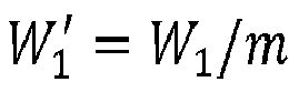
- In a next step an initial 4D
correlation volume C 0 320 may be determined based onfeature maps F 1 140 andF 2 150. In casefeature map F 1 140 has been sub-sampled to generate reduced feature map F 1', initial 4Dcorrelation volume C 0 320 may be determined based on reduced feature map F 1' andfeature map F 2 150. Each entry in C 0 may represent a correlation between a pixel 114 p = (xp, yp ) inpixel grid 112 ofimage 110 and a pixel 124 q = (xq,yq ) inpixel grid 122 ofimage 120. The correlation is denoted as Cp,q. In casefeature map F 1 140 has been sub-sampled to generate reduced feature map F 1', each value in initial 4Dcorrelation volume C 0 320 may represent a correlation between an atomic portion (or patch) of thepixel grid 112 ofimage 110 with center p = (xp,yp ) and a pixel q = (xq,yq ) inpixel grid 122 ofimage 120. This correlation is similarly denoted as Cp,q. For the sake of clarity in the following description below, reference will only be made to p as apixel 114 inpixel grid 112 ofimage 110. However, it is to be understood that, in case offeature map F 1 140 having been sub-sampled to generate reduced feature map F 1', p = (xp,yp ) may refer to the center of an atomic portion (or patch) of thepixel grid 112 ofimage 110. Each pixel 114 (or portion) p inpixel grid 112 corresponds to a local feature descriptor 144 D(p) in the grid oflocal feature descriptors 142 of feature map F 1 140 (or the respective reduced grid of local feature descriptors of reduced feature map F 1'). Similarly, each pixel 124 q inpixel grid 122 corresponds to a local feature descriptor 154 D(q) in the grid oflocal feature descriptors 152 offeature map F 2 150. Initialcorrelation volume C 0 320 comprises all possible pixel-pixel correlation values C0 ( p,q ). The correlation value C0 ( p,q ) is determined by calculating a similarity value based on D(p) and D(q).
- Each similarity value may be a real number representing a measure of similarity between the local image descriptors on D( p ) and D(q). Any suitable method for calculating similarity values for a pair of local image descriptors may be used. In a specific embodiment each similarity value is determined as a cosine similarity between the local image descriptors of a pair of local image descriptors on D( p ) and D(q) based on the scalar product between the respective d-dimensional vectors representing the local image descriptors. In an embodiment of the invention each value C0 ( p,q ) is a number in the range between 0 and 1. Initial
correlation volume C 0 320 may have dimensions H 1 × W1 × H 2 × W 2. In the case wherefeature map F 1 140 has been sub-sampled to generate reduced feature map F 1', initialcorrelation volume C 0 320 may have dimensions H 1' × W1'×H 2 × W 2. - Once initial
correlation volume C 0 320 has been determined,iterative pyramid construction 330 is applied to C 0 to generate high-level correlation volume CL 340.Iterative pyramid construction 330 includes4D Aggregation step 334 for iteratively determining higher-level correlation volumes Cℓ for 1 ≤ ℓ ≤ L. In a first iteration step, first-level correlation volume C 1 is determined. First-level correlation volume C 1 is comprised of correlation values C 1( p , q), which represent correlations between first-level patches ofpixel grid 112 andpixel grid 122. Generally, a patch is a rectangular portion of a pixel grid (e.g. pixel grid 112 or pixel grid 122). In order to facilitate a concise discussion of the invention, the following is described with patches of width and height 2 (denoted aspatch size 2 × 2), including either 2 × 2 pixels of a pixel grid or 2 × 2 patches of the previous iteration step. However, the specific patch size is not to be construed as limiting to the present invention, and other patch sizes (e.g. 2 × 3, 3 × 2, 3 × 3, or 4 × 4) may be utilized in embodiments of the present invention. The center of a patch ofpixel grid 112 is denoted as p = (xp, yp ) and the center of a patch ofpixel grid 122 is denoted as q = (xq,yq ). For a consistent notation, 0-level patches are considered to be pixels of the respective pixel grids. With this notation, an ℓ-level patch has 2 × 2 children patches of level ℓ - 1 for 1 ≤ ℓ ≤ L. A vector from the center of an ℓ-level patch to the i th (ℓ - 1)-level child patch of the ℓ-level patch is denoted



-
Aggregation step 334 can be implemented using 4D convolutions with a fixed sparse kernel, where non-zero values encode the parent-children relations in the pyramid. So far, this formulation is able to handle rigid transformations, where all child patches strictly fit into the boundaries of the parent patch. Some embodiments include an extension of the aggregation procedure, which allows for a certain degree of local deformations. In these embodiments, small local deformations of child patches may be taken into account at each iteration level by an additional 2D max-poolingstep 332 performed before4D Aggregation step 334 in each iteration cycle. Technically, the 2D max-pooling is performed with a suitable kernel (e.g. ofsize 3 × 3) along both dimensions ofpixel grid 122 of thesecond Image I 2 120. - In an alternative embodiment, deformations may be taken into account by adapting
aggregation step 334, such that the aggregation step aggregates the highest correlation of each of the child (ℓ - 1)-level patches at position


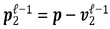


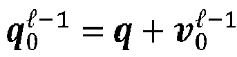


- Here, Ω i denotes a small local neighborhood centered at

- Alternatively, deformations may also be taken into account by averaging over correlations of the (ℓ - 1)-level patch at position


- The number of (ℓ - 1)-level patches in the neighborhood Ωi of
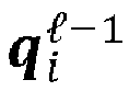

- As a final step in each iteration,
rectification step 336 can optionally be performed to strengthen consistent correlations and discard spurious ones.Rectification step 336 may be implemented as a power non-linearity x → max(0, xγ ) applied at the end of each iteration step to the output correlation values of4D aggregation step 334. The specific value of γ can be adapted to the circumstances and is not to be construed as limiting for the present invention. In an embodiment, γ = 1.5. - Mathematically, the receptive field of a parent patch doubles along x- and y-dimensions at each pyramid level, hence rapidly reaching the size of the full image, at which point the aggregation process naturally ends.
Figure 4 illustrates the deformable pyramidal structure, which is enforced byiterative pyramid construction 330. The figure shows patches at three levels ofiterative pyramid construction 330. Atlevel ℓ + 2, four neighboring (ℓ + 2)-level patches level patch 412 is aggregated from (ℓ + 1)-level correlations for (ℓ + 1)-level patches level patch 422 is aggregated from ℓ-level correlations for ℓ-level patches - Returning to
Figure 3 , the output of the iterative pyramid construction applied toC 0 320 is consolidated high-level correlation volume CL 340. The third and fourth dimensions of CL 340, which correspond to the dimensions of thepixel grid 122 of I 2 120, are reduced by afactor 2L, where L is the number of iterations (or pyramid levels) ofiterative pyramid construction 330. The reduction factor may be different for other choices of the patch size in iterativepyramidal construction 330 and is not to be construed as limiting for the present invention. In embodiment CL 340 may have dimensions H 1 × W1 × H 2 × W 2. Ifoptional sub-sampling step 310 is performed, CL 340 may have dimensions H 1 ' × W 1 ' × H 2 × W2. - The consolidated high-level correlation volume CL represents the correlations between large deformable high-level patches. Ideally, a high-level patch centered at pixel p has a unique match in image I 2, i.e., there should exist only one q such that CL ( p,q) has a high value, while all other correlations for q' ≠ q will be close to 0. While this constraint is not realistic for pixel-level descriptors due to repetitive patterns, plain regions without structure, or severe appearance changes, it appears as a natural property for high-level patches in CL 340. In fact, the larger a patch is, the easier it is to resolve ambiguities and hard correspondences due to the larger context. Based on these considerations,
uniqueness matching loss 350 is determined from CL 340 that encourages the property of a unique match for every high-level patch.Uniqueness matching loss 350 is the output value ofcorrelation module 300 and represents an embodiment ofloss 170 as illustrated inFigure 1 . Since each high-level patch is dynamically built at test-time upon a deformable subset of pixel-level correlations, this loss is automatically back-propagated to optimal pixel correlations fittingiterative pyramid construction 330, and hence to pixel level local image descriptors. - The following presents an exemplary implementation of
uniqueness matching loss 350. Other implementations are within the scope of the present invention as long as the resulting loss rewards the uniqueness of matches between high-level patches in CL such that a high-level patch inI 1 110 has only one matching high-level patch inI 2 120. For the sake of a clear description of the exemplary implementation ofuniqueness matching loss 350, CL may be formally reshaped as a 2-dimensional tensor of size
sub-sampling step 310 is performed ofsize 


- The expression H 1 × W 1 in equation (5) is replaced by H 1 ' × W 1 ' in case
optional sub-sampling step 310 is performed to generate reduced feature map F 1'. Given that CL is ℓ1-normalized, the uniqueness loss concretely encourages all values inC L to be close to 0 except one per row (i.e. one per high-level patch) that will be close to 1. - In an embodiment, the asymmetric loss


correlation module 300. In a specific embodiment of the invention, the model is trained with batches of image pairs (e.g. 10 image pairs, 12 image pairs, 16 image pairs, or 24 image pairs). A portion of the image pairs of the batch (e.g. half of the image pairs, 2/3 of the image pairs, a quarter or three quarters of the image pairs) are trained with unsupervised loss 350 (e.g.


US Patent 11176425 B2 

-
Figure 5 is a functional block diagram illustrating a computer-implementedmethod 500 of unsupervised neural network training for learning of local image descriptors, according to an embodiment. The method is implemented as a training phase for a neural network (e.g. neural network 130) as illustrated inFigures 1 and3 . The method starts atstep 510, at which a pair of training images is obtained. Obtaining the training images encompasses that they can be received from any memory location (e.g. a local or remote computing system, a local or remote database, a cloud storage or any other memory location known in the field) on which they are stored. Alternatively, the images may be automatically retrieved from any of these memory locations. The images of the obtained image pair depict a same scene or visual content (e.g. a same object, a same person, a same architectural structure, and/or a same natural structure) such that both images include corresponding portions related to same features of the depicted scene. No dense or sparse ground-truth correspondences are known for the images of the image pair in advance of the training phase. The obtained image pair includes a first image (e.g. image 110) with a first pixel grid (e.g. pixel grid 112) and a second image (e.g. image 120) with a second pixel grid (e.g. pixel grid 122). The pixel grids differ in at least one aspect. The first pixel grid may have different horizontal and/or vertical dimensions different from those of the second pixel grid. Additionally or alternatively, the pixel values of at least a portion of the pixels in the first pixel grid may differ from pixel values of the respective pixels in the second pixel grid. - At
step 520 the neural network is applied to the first image to generate a feature map F 1 (e.g. feature map 140). Additionally, the neural network is applied to the second image to generate a feature map F 2 (e.g. feature map 150). The neural network has an initial set of internal, learnable parameters (e.g. parameters 132). Feature map F 1 comprises a first grid of local descriptors (e.g. grid of local descriptors 142), wherein each local descriptor (e.g. local descriptor 144) in the first grid of local descriptors corresponds to a pixel within the first pixel grid. Each local descriptor of the first grid of local descriptors is a computer-processable description of the local environment of the corresponding pixel in the first pixel grid. Feature map F 2 comprises a second grid of local descriptors (e.g. grid of local descriptors 152), wherein each local descriptor (e.g. local descriptor 154) in the second grid of local descriptors corresponds to a pixel within the second pixel grid. Each local descriptor of the second grid of local descriptors is a computer-processable description of the local environment of the corresponding pixel in the second pixel grid. A local image descriptor may be represented as a d-dimensional vector and is extracted from a pixel grid through the application of the neural network on the respective image. - At
step 530 an initial correlation volume C 0 (e.g. initial correlation volume 320) is determined based on F 1 and F 2. Initial correlation volume C 0 comprises local correlations of pixels of the first pixel grid with pixels of the second pixel grid. Each local correlation is determined for a pixel of the first pixel grid and a pixel of the second pixel grid based on a first corresponding local image descriptor in the and first grid of local image descriptors and a second corresponding local image descriptor in the second grid of local image descriptors. The first corresponding local image descriptor corresponds to the pixel in the first pixel grid and the second corresponding local image descriptor corresponds to the pixel in the second pixel grid. In an embodiment, the correlation C0 ( p,q ) between a pixel p of the first pixel grid and a pixel q of the second pixel grid is determined as a similarity between local image descriptors D(p) and D(q). D(p) corresponds to p and is comprised in the first grid of local image descriptors. D(q) corresponds to q and is in comprised the second grid of local image descriptors. The similarity between local image descriptors D(p) and D(q) may be determined as a cosine similarity based on the scalar product of the d-dimensional vectors representing D(p) and D(q). - At
step 540, a high-level correlation volume CL (e.g. high-level correlation volume 340) is determined based on C 0 by iterative pyramid construction (e.g. iterative pyramid construction 330). High-level correlation volume CL comprises aggregated high-level correlations between iteratively constructed high-level patches of the first and second pixel grids. Each high-level patch of the first pixel grid is a rectangular portion of the first pixel grid. Each high-level patch of the second pixel grid is a rectangular portion of the second pixel grid. CL may be iteratively constructed starting from C 0. A first iteration step may comprise aggregating local correlations of C 0 to first-level correlations between first-level patches of the first pixel grid and first-level patches of the second pixel grid, thereby generating a first-level correlation volume C 1. The first-level correlation between a first-level patch of the first pixel grid and a first-level patch of the second pixel grid may be determined as an averaged sum of local correlations between corresponding pixels in the first-level patch of the first pixel grid and the first-level patch of the second pixel grid. Each of the local correlations in the averaged sum of local correlations may have a maximum correlation value among a plurality of neighboring local correlation values. - A subsequent (n + 1)th iteration step for 1 ≤ n < L, may comprise generating an (n + 1)-level correlation volume C n+1 by aggregating n-level correlations of Cn to (n + 1)-level correlations between (n + 1)-level patches of the first pixel grid and (n + 1)-level patches of the second pixel grid. The (n + 1)-level patches may be comprised of neighboring n-level patches of the respective pixel grid. The aggregated n-level correlations correspond to the neighboring n-level patches of the correlated (n + 1)-level patches. The (n + 1)-level correlation between an (n + 1)-level patch of the first pixel grid and an (n + 1)-level patch of the second pixel grid may be determined as an averaged sum of n-level correlations between corresponding n-level patches of the (n + 1)-level patch of the first pixel grid and the (n + 1)-level patch of the second pixel grid. Each of the n-level correlations in the averaged sum of n-level correlations may have a maximum correlation value among a plurality of neighboring n-level correlation values.
- At
step 550, a uniqueness matching loss (e.g. uniqueness matching loss 350) is determined for F 1 and F 2 based on CL . The uniqueness matching loss provides a measure for a deviation of F 1 and F 2 from optimal feature maps. The uniqueness matching loss is configured to indicate a low deviation to optimal feature maps if, based on the high-level correlations in CL , each high-level patch of the first pixel grid has a unique (i.e. only one) match among the high-level patches of the second pixel grid and each high-level patch of the second pixel grid has a unique (i.e. only one) match among the high-level patches of the first pixel grid. Accordingly, the uniqueness matching loss has low values if for each high-level patch of the first and the second pixel grids only one high-level correlation in CL corresponding to the respective patch has a high correlation value and all other high-level correlations in CL corresponding to the respective high-level patch have a low correlation value. A high correlation value may be close to 1, whereas a low correlation value may be close to 0. - At
step 560, the neural network is trained by minimizing a loss function based on the uniqueness matching loss to generate an optimized set of parameters. Minimizing the loss function may include performing backpropagation based on the loss function to determine a new set of parameters which achieves a lower uniqueness matching loss in a subsequent training step. Training the network may further include repeating the steps of the method with the optimized set of parameters for a predetermined number of times or until the optimized set of parameters converges, thereby generating a trained neural network adapted for determining local image descriptors. -
Figure 6 is a functional block diagram illustrating computer-implementedmethod 600 of determining corresponding portions in images with a trained neural network according to an embodiment, wherein the neural network has been trained according to the method illustrated inFigure 5 . The method starts atstep 610 where the trained neural network is applied to first new image (e.g. image 210) to generate a first feature map (e.g. feature map 240) comprising a first grid of local image descriptors. Atstep 620 the trained neural network is applied to a second new image (e.g. image 220) to generate a second feature map (e.g. feature map 250) comprising a second grid of local image descriptors. The first and second new images may depict a same scene using different pixel grids. At step 630 a correspondence (e.g. one of correspondences 270) between a portion of the first new image and a portion of the second new image is identified based on the first and second grids of local image descriptors. The corresponding portions identified relate to a same part of the depicted scene. Additional correspondences between the images may be determined either between keypoints of the images or for each pixel in the images (i.e. dense correspondences). Step 630 may be performed by matchingmodule 260 shown inFigure 2 . - First details of an exemplary implementation of the presented training method as used for a set of experiments will be discussed. Then, different datasets and benchmarks used in the experiments will be introduced. Finally, the details of the experiments and comparisons to other technique will be presented.
- As training data, 150,000 pairs are used from the SfM-120k dataset (Radenovic et al., "Revisiting Oxford and Paris: Large-scale image retrieval benchmarking", CVPR, 2018), which contains images from famous landmarks. These training pairs are obtained using the overlap of observations in a SfM model built with COLMAP and provided with the dataset. This process is done with SIFT, which requires no supervision, and only serves to verify whether two images depict the same scene, but does not guide the matching at all. Random crops of size 256 × 256 are performed on these pairs. To generate the synthetic pairs, images randomly sampled from this dataset and standard data augmentation techniques are applied. In particular, random pixel and color jittering, random rescaling, rotations and homographies are used.
- In an exemplary implementation of network fθ, gradients with a 5 × 5 convolution with
stride 1 and 128 output channels may first be extracted. Then 4 × 4 non-overlapping gradient patches are embedded into 512-dimensional features using a convolution ofkernel 4 × 4 withstride 4. Subsequently, a series of pointwise and depthwise convolutions are applied. The exemplary implementations uses seven such blocks, with depthwise convolutions using 9 × 9 kernels. Finally, a last pointwise convolution and PixelShuffle operation is applied to obtain a feature map F with d = 128 dimensions. - HPatches (Balnats et al., "A Benchmark and evaluation of handcrafted and learned local descriptors", CVPR, 2017) consists of 116 image sequences with varying photometric and viewpoint changes. Each sequence contains a reference image and five source images related by a homography to the source image taken under different viewpoint or illumination.
- ETH3D (Schöps et al., "A multi-view stereo benchmark) contains indoor and outdoor sequences captured using a hand-held camera and registered with SfM. Image pairs are generated by sampling frames with a fixed interval. It is used to evaluate the robustness to viewpoint changes as the baseline widens for increasing intervals.
- Aachen Day-Night v1.1 (Zhang et al., "Reference pose generation for long-term visual localization via learned features and view synthesis", IJCV, 2021) is a large-scale outdoor visual localization benchmark. The Day-Night split is specifically considered to measure the generalization performance of the embodiments of the present invention, as it features large viewpoint changes and severe illumination changes due to the day/night duality. For this task, the following method is used: in a first step, a global SfM map is built from the database images, and in a second step, query images are localized with regard to this mapping. The computational complexity of a complete matching is handled via the use of image retrieval with AP-GeMLM18 (Revaud et al., "Learning with average precision: Training image retrieval with a listwise loss, ICCV, 2019) global descriptors. The number of image pairs is reduced to the top-20 nearest neighbors, during both the mapping and the query phases. Finally, 20,000 local features for each of these retrieved images are extracted and matched to estimate first the global map and then the camera poses.
- The performance of the PUMP descriptors (i.e. the local image descriptors extracted from an image by applying trained
neural network 230 to the image), according to embodiments, is evaluated in a dense or quasi-dense manner using DeepMatching (Revaud et al., "DeepMatching: Hierarchical deformable dense matching", IJCV, 2016). In this exemplary implementation ofmatching module 260, the basic pixel descriptor of DeepMatching is replaced by the PUMP descriptors. The rest of the pipeline is left unchanged, except for the built-in cycle-consistency verification that has been enhanced to include nearest neighbors as well. It is noted that the output of DeepMatching is not dense but quasi-dense, as it outputs one correspondence per atomic patch from the first image. When dense warp fields are required, a densification technique is used following COTR's scheme (Jiang et al., "Cotr: Correspondence transformer for matching across images", ICCV, 2021) which includes linearly interpolate matches using a Delaunay triangulation. - For HPatches, evaluation is performed on all image pairs from image data set that features viewpoint changes. Table 1 represents both quasi-dense and fully-dense (i.e. interpolated) outputs. Two models according to embodiments of the present invention are evaluated: one trained solely from self-supervised pairs (S), i.e., obtained via data augmentation, and one including unsupervised pairs as well (S+U). Without interpolation, the self-supervised model (S) performs slightly better than the model trained with unsupervised pairs (S+U). This is not surprising given that it is trained exclusively from synthetic augmentations (homographies) fitting exactly the distribution of the test set. In fully-dense mode, the unsupervised model (S+U) outperforms the self-supervised model (S), indicating that the unsupervised loss allows for production of fewer outliers (as these strongly impair Delaunay interpolation) and is thus more robust. Overall, whether it be used with or without interpolation, both models outperform all state-of-the-art approaches by a large margin. Both models according to embodiments of the present invention also significantly outperform the recently proposed unsupervised WarpC matching loss (Truong et al.,"Warp consistency of unsupervised learning of dense correspondences", ICCV, 2021). Altogether, these results highlight the excellent capacity of our pyramidal matching prior according to embodiments of the present invention in the case of large planar areas without discontinuities.

- Embodiments of the present invention are evaluated in a more challenging setting with real image pairs from ETH3D featuring viewpoint changes on complex 3D shapes and many discontinuities in the optical flow. Since the ground-truth is sparse and not necessarily aligned with the quasi-dense output, only results with the densely-interpolated variant for various frame intervals (e.g. rate) are presented in Table 2. It is observed that the model trained with unsupervised pairs significantly outperforms the self-supervised one by up to 25% (relative gain). This highlights the superior robustness against realistic noise of the model trained by injecting matching priors. Overall, it also outperforms all existing approaches, scoring the first or second Average End Point Error (AEPE) for all rate intervals. In addition, the models according to embodiments are significantly faster than other methods such as DPM (Hong and Kim, "Deep matching prior: Test-time optimization for dense correspondence", ICCV, 2021), which requires multiple minutes per testing pair for specific fine-tuning on each one.
Method AEPE↓ rate3 rate5 rate7 rate9 rate11 rate13 rate15 LiteFlowNet 1.66 2.58 6.05 12.95 29.67 52.41 74.96 PWC-Net 1.75 2.10 3.21 5.59 14.35 27.49 43.41 DGC-Net 2.49 3.28 4.18 5.35 6.78 9.02 12.23 GLU-Net 1.98 2.54 3.49 4.24 5.61 7.55 10.78 RAFT 1.92 2.12 2.33 2.58 3.90 8.63 13.74 DMP 1.78 2.07 2.52 3.07 4.72 6.14 7.47 COTR + Interp. 1.71 1.92 2.16 2.47 2.85 3.23 3.76 PUMP (S)+DM+ Interp. 1.77 2.81 2.39 2.39 3.56 3.87 4.57 PUMP (S+U)+DM+ Interp. 1.67 1.86 2.12 2.37 2.81 3.41 3.69 - The impact of the matching priors leveraged during training in a sparse matching setting is evaluated by comparing again the performance achieved by the PUMP (S) and PUMP (S+U) models according to embodiments of the present invention. Since the method according to the invention produces dense descriptor maps, an external keypoint detector is needed to select repeatable locations in the image scale-space. To make the evaluation as comprehensive as possible, the performance for three standard detectors is measured: SIFT (Lowe, "Object recognition from local scale invariant features", ICCV, 1999), R2D2 (Revaud et al., "R2D2: repeatable and reliable detector and descriptor", NeurIPS, 2019) and SuperPoint (DeTone et al.: "Self-supervised interest point detection and description", CVPR Workshops, 2018). For each detector, the same number of keypoints are extracted at the same locations and scales for each method, making the evaluation fair and strictly centered on the descriptors.
- A comprehensive study of the overall descriptor quality is performed by evaluating jointly on two complementary tasks, namely in terms of keypoint matching on HPatches and localization accuracy on Aachen-Night. For HPatches, the Mean Matching Accuracy (MMA) is measured by following the experimental protocol of Dusmanu et el., "D2-Net: A trainable CNN for joint description and detection of local features", CVPR, 2019. The MMA corresponds to the average percentage of correct matches for all image pairs with regard to a specified error threshold in pixels. Visual localization performance is measured as the percentage of queries successfully localized with regard to specified thresholds on the camera position and orientation. Table 3 presents results for each keypoint detector and each model on both benchmarks. The results show that the models according to embodiments of the present invention, including the self-supervised model (S), significantly outperform their respective keypoint baselines on HPatches. Interestingly, this does not translate into localization accuracy - in fact the self-supervised model constantly yields an inferior localization accuracy compared to baseline keypoints. This discrepancy is explained by the fact that self-supervision cover simple transformation like homographies well, but fail to model more realistic changes. In contrast, the model trained with unsupervised pairs (S+U) largely outperforms the self-supervised model by 6 points on average and all baseline keypoints as well, despite being trained without pixel-level supervision.
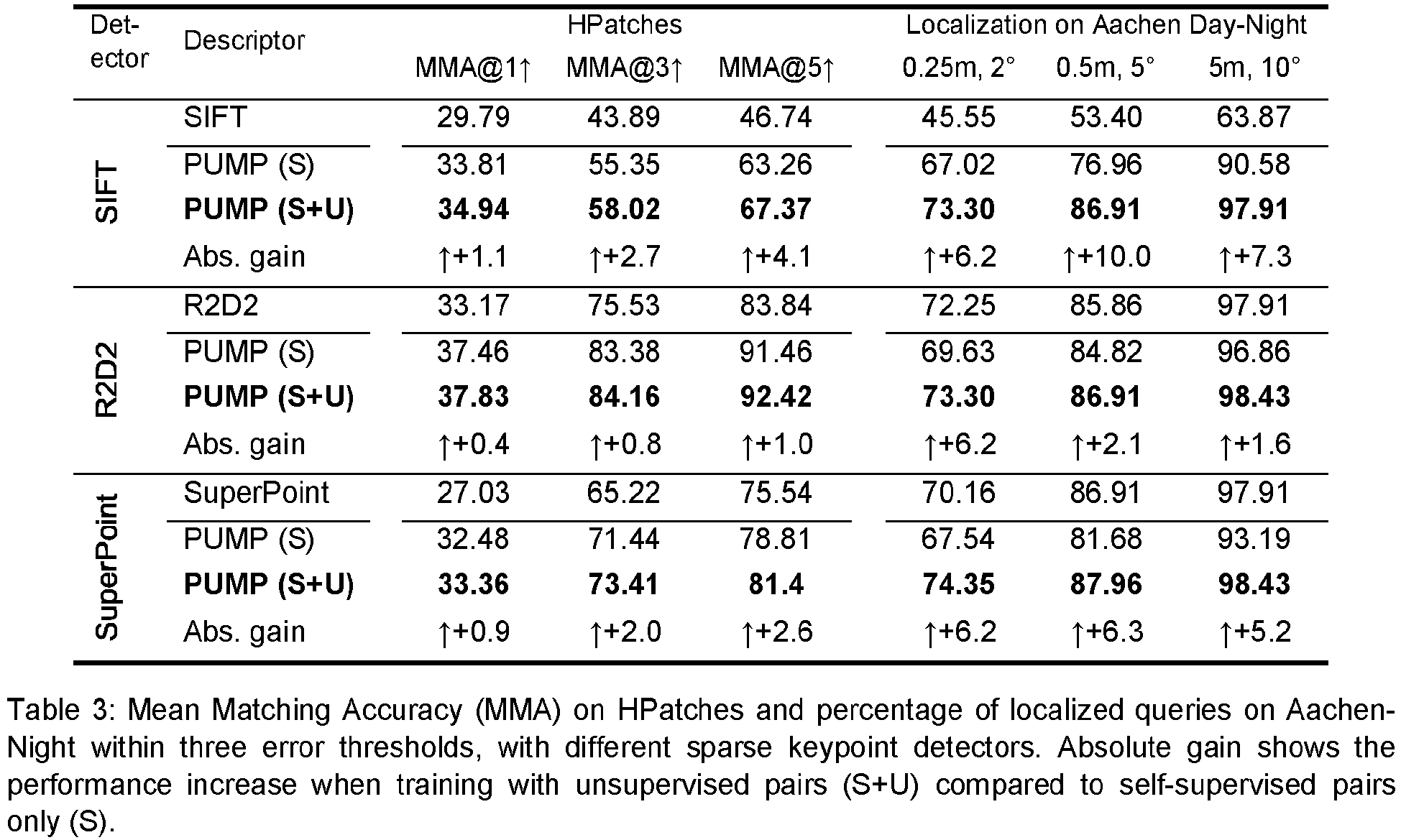
-
Figure 7 illustrates a comparison of the performance of models according to the present invention with the state of the art on HPatches (in this case R2D2's keypoint detector is used to extract the keypoints). The figure shows matching results on the HPatches dataset in terms of Mean Matching Accuracy (MMA) for various error thresholds. The models according to embodiments of the invention significantly outperform all state-of-the-art methods, including the recent Sparse NCNet (Rocco et al., "Neighbourhood consensus network", NeurIPS, 2018) and the self-supervised method CAPS-U (Melekhov et al., "Digging into self-supervised learning of feature descriptors", 3DV, 2021). - Although the above embodiments have been described within the context of method steps, they also represent a description of a corresponding component, module or feature of a corresponding apparatus or system.
- Some or all of the method steps may be implemented by a computer in that they are executed by (or using) a processor, a microprocessor, an electronic circuit or processing circuitry.
- The embodiments described above may be implemented in hardware or in software. The implementation can be performed using a non-transitory storage medium such as a computer-readable storage medium, for example a floppy disc, a DVD, a Blu-Ray, a CD, a ROM, a PROM, an EPROM, an EEPROM or a FLASH memory. Such computer-readable media can be any available media that can be accessed by a general-purpose or special-purpose computer system.
- Generally, embodiments can be implemented as a computer program product with a program code or computer-executable instructions, the program code or computer-executable instructions being operative for performing one of the methods when the computer program product runs on a computer. The program code or the computer-executable instructions may, for example, be stored on a computer-readable storage medium.
- In an embodiment, a storage medium (or a data carrier, or a computer-readable medium) comprises, stored thereon, the computer program or the computer-executable instructions for performing one of the methods described herein when it is performed by a processor. In a further embodiment, an apparatus comprises one or more processors and the storage medium mentioned above.
- In a further embodiment, a system comprises means, for example processing circuitry such as a processor communicating with a memory, the means being configured to, or adapted to, perform one of the methods described herein.
- A further embodiment comprises a computer having installed thereon the computer program or instructions for performing one of the methods described herein.
- The above-mentioned methods and embodiments may be implemented within a system architecture such as illustrated in
Figure 8 , which comprisesserver 800 and one or more client devices 802 that communicate over a network 804 (which may be wireless and/or wired), such as the Internet, for data exchange.Server 800 and the client devices 802 include a data processor 812 and memory 813 such as a hard disk. The client devices 802 may be any device that communicates withserver 800, includingautonomous vehicle 802b,robot 802c,computer 802d, orcell phone 802e. - More precisely, in one embodiment, the
method 500 for unsupervised neural network training for learning of local image descriptors is performed atserver 800. The server may provide the trained neural network (e.g. trained neural network 230) to any of the devices, which may then performmethod 600 based on the received trained neural network to compute optimal local image descriptors for determining whether a true match exists between image pairs. In various embodiments, the determination that a true match exists is used in different applications including, visual localization and mapping, pose estimation, Structure-from-Motion, 3D reconstruction, and image search that rely on such descriptors. In an exemplary embodiment, one of the devices 802 performs bothmethods autonomous vehicle 802b (orrobot 802c) comprises an optical sensor which obtains a first image of the surroundings of the vehicle (or the robot). In addition, the vehicle (or the robot) stores a second image (with location information) of the surroundings of the vehicle (or the robot) onmemory device 813b/c.Vehicle 802b (orrobot 802c) then performsmethod 600 with the first and second image to identify corresponding portions in the images to determine a position of the vehicle (or the robot) within the surroundings of the vehicle (or the robot) via visual localization.
Claims (17)
- A computer-implemented method of unsupervised neural network training for learning of local image descriptors, the method comprising:obtaining a first pair of images depicting a same scene, the pair of images including a first image with a first pixel grid and a second image with a second pixel grid, wherein the first pixel grid differs from the second pixel grid;applying a neural network having an initial set of parameters to the first image and the second image to generate a feature map F 1 for the first image and a feature map F 2 for the second image, F 1 comprising a first grid of local image descriptors and F 2 comprising a second grid of local image descriptors, wherein each local image descriptor in the first grid of local image descriptors corresponds to a respective pixel within the first pixel grid and each local image descriptor in the second grid of local image descriptors corresponds to a respective pixel within the second pixel grid;determining an initial correlation volume C 0 based on F 1 and F 2, wherein C 0 comprises local correlations of pixels of the first pixel grid with pixels of the second pixel grid, wherein each local correlation between a pixel of the first pixel grid and a pixel of the second pixel grid is determined based on the local image descriptors corresponding to the correlated pixels;determining a high-level correlation volume CL based on C 0 by iterative pyramid construction, wherein CL comprises aggregated high-level correlations between iteratively constructed high-level patches of the first and second pixel grids, each patch being a rectangular portion of the respective pixel grid;determining a uniqueness matching loss for F 1 and F 2 based on CL , the uniqueness matching loss providing a measure for a deviation of F 1 and F 2 from optimal feature maps, wherein the deviation from optimal feature maps is low if, based on the high-level correlations in CL , each high-level patch of the first and the second pixel grids has a unique match among the high-level patches of the respective other pixel grid; andtraining the neural network by minimizing a loss function based on the uniqueness matching loss to generate an optimized set of parameters, thereby generating a trained neural network adapted for determining optimal local image descriptors.
- The method of claim 1, further comprising:applying the trained neural network to a first new image to generate a third feature map comprising a third grid of local image descriptors;applying the trained neural network to a second new image to generate a fourth feature map comprising a fourth grid of local image descriptors, wherein the first and second new images depict a same new scene using different pixel grids; andidentifying a correspondence between a portion of the first new image and a portion of the second new image based on the third and fourth grids of local image descriptors, wherein the corresponding portions relate to a same part of the depicted new scene.
- The method of claim 1 or 2, wherein obtaining the first pair of images comprises obtaining a batch of image pairs, wherein the batch of image pairs includes the first pair of images and a second pair of images, the second pair of images comprising a source image and an augmented image, the augmented image being generated synthetically from the source image via data augmentation, wherein ground-truth correspondences between the source image and the augmented image are obtained from the data augmentation,
wherein the method further comprises:applying the neural network with the initial set of parameters to the source image and the augmented image to generate respective feature maps for the source image and the augmented image, each feature map comprising a respective grid of local image descriptors; anddetermining a pixel-wise ranking loss based on the grid of local image descriptors corresponding to the source image, the grid of local image descriptors corresponding to the augmented image, and the ground-truth correspondences between the source image and the augmented image,wherein training the neural network comprises minimizing the loss function based on a weighted sum of the uniqueness matching loss and the pixel-wise ranking loss. - The method of any one of the preceding claims, wherein determining CL comprises:aggregating local correlations of C 0 to first-level correlations between first-level patches of the first pixel grid and first-level patches of the second pixel grid, thereby generating a first-level correlation volume C 1; andfor n between 1 and L - 1, iteratively aggregating n-level correlations of Cn to (n + 1)-level correlations between (n + 1)-level patches of the first pixel grid and (n + 1)-level patches of the second pixel grid, thereby generating an (n + 1)-level correlation volume C n+1, the (n + 1)-level patches being comprised of neighboring n-level patches of the respective pixel grid and the aggregated n-level correlations corresponding to the neighboring n-level patches of the correlated (n + 1)-level patches.
- The method of claim 4, wherein aggregating local correlations of C 0 comprises determining a first-level correlation between a first-level patch of the first pixel grid and a first-level patch of the second pixel grid as an averaged sum of local correlations between corresponding pixels in the first-level patch of the first pixel grid and the first-level patch of the second pixel grid, and
wherein aggregating n-level correlations of Cn comprises determining an (n + 1)-level correlation between an (n + 1)-level patch of the first pixel grid and an (n + 1)-level patch of the second pixel grid as an averaged sum of n-level correlations between corresponding n-level patches of the (n + 1)-level patch of the first pixel grid and the (n + 1)-level patch of the second pixel grid. - The method of claim 5, wherein each of the local correlations in the averaged sum of local correlations has a maximum correlation value among a plurality of neighboring local correlation values in C0 , and wherein each of the n-level correlations in the averaged sum of n-level correlations has a maximum correlation value among a plurality of neighboring n-level correlation values in Cn , or
wherein each of the local correlations in the averaged sum of local correlations is determined as an average correlation value of a plurality of neighboring local correlation values in C 0, and wherein each of the n-level correlations in the averaged sum of n-level correlations is determined as an average correlation value among a plurality of neighboring n-level correlation values in Cn. - The method of any one of claims 4 to 6, wherein each (n + 1)-level patch of the first or second pixel grid comprises 2×2 n-level patches of the respective pixel grid.
- The method of any one of the preceding claims, wherein the initial correlation volume C 0 has a first dimension corresponding to a first dimension of F 1 and a second dimension corresponding to a second dimension of F 1, and wherein generating C 0 comprises subsampling of F 1 by a predetermined factor in the first and second dimensions to generate a subsampled feature map having a first reduced dimension H 1' and a second reduced dimension W 1'.
- The method of claim 8, wherein subsampling F 1 comprises:dividing the first pixel grid in non-overlapping atomic patches, each atomic patch including a plurality of pixels; andfor each atomic patch, determining one resulting local descriptor based on the local image descriptors corresponding to the pixels of the respective patch, wherein the resulting local descriptor represents all pixels of the atomic patch in the subsampled feature map.
- The method of claim 9, wherein determining C 0 comprises, for each atomic patch of the first pixel grid, determining correlations of the atomic patch with each pixel of the second pixel grid, each correlation being determined based on the local image descriptor representing the respective atomic patch in the subsampled feature map and the local image descriptor of F 2 corresponding to the correlated pixel of the second pixel grid.
- The method of claim 9 or 10, wherein each atomic patch has a size of 4 by 4 pixels, and wherein the first dimension of F 1 is 4 × H 1' and the second dimension of F 1 is 4 × W 1 '.
- The method of any one of claims 4 to 11, wherein C 0 is a 4-dimensional tensor and the third and fourth dimensions of C 0 correspond to the first and second dimensions of F 2, and wherein, for each n between 0 and L - 1, C n+1 is a 4-dimensional tensor and generating Cn+1 comprises performing a 2-dimensional subsampling of Cn such that the third and fourth dimensions of C n+1 are each reduced by a predetermined factor compared to the third and fourth dimensions of Cn.
- The method of any one of claims 4 to 12, wherein generating C n , for each n between 1 and L, comprises performing a rectification transformation for each n-level correlation of Cn.
- The method of any one of claims 4 to 13, wherein the optimal image descriptors identify correspondences between portions of the first image and the second image depicting a scene with similar visual content but different viewpoints or different lighting conditions.
- A computer-implemented method for identifying correspondences between a pair of input images, the method comprising:receiving the input image pair including a first input image and a second input image;processing the input image pair with a neural network trained by performing a method of unsupervised learning of local image descriptors according to one of claims 1 to 14, the trained neural network generating local image descriptors for the input image pair;extracting correspondences between portions of the input image pair based on the image descriptors, each extracted correspondence mapping a portion of the first input image to a portion of the second input image;determining with the extracted correspondences whether a true match exists between the input image pair, a true match existing between the input image pair when corresponding portions of the image pair depict a same scene; andoutputting whether a true match exists between the image pair.
- A system comprising:a processing unit; anda memory connected to the processing unit, wherein the memory comprises computer-executable instructions that, when executed by the processing unit, cause the processing unit to perform a method according to one of claims 1 to 15.
- One or more computer-readable media having computer-readable instructions stored thereon which, when executed by a processing unit, cause the processing unit to perform a method according to one of claims 1 to 15.
Priority Applications (4)
| Application Number | Priority Date | Filing Date | Title |
|---|---|---|---|
| EP22305384.4A EP4254354B1 (en) | 2022-03-28 | 2022-03-28 | System and method using pyramidal and uniqueness matching priors for identifying correspondences between images |
| US18/103,074 US12626489B2 (en) | 2022-03-28 | 2023-01-30 | System and method using pyramidal and uniqueness matching priors for identifying correspondences between images |
| KR1020230037955A KR20230140530A (en) | 2022-03-28 | 2023-03-23 | System and method using pyramidal and uniqueness matching priors for identifying correspondences between images |
| JP2023050502A JP2023145404A (en) | 2022-03-28 | 2023-03-27 | System and method for using pyramids and uniqueness matching flyers to identify correspondences between images |
Applications Claiming Priority (1)
| Application Number | Priority Date | Filing Date | Title |
|---|---|---|---|
| EP22305384.4A EP4254354B1 (en) | 2022-03-28 | 2022-03-28 | System and method using pyramidal and uniqueness matching priors for identifying correspondences between images |
Publications (2)
| Publication Number | Publication Date |
|---|---|
| EP4254354A1 true EP4254354A1 (en) | 2023-10-04 |
| EP4254354B1 EP4254354B1 (en) | 2025-01-22 |
Family
ID=81307252
Family Applications (1)
| Application Number | Title | Priority Date | Filing Date |
|---|---|---|---|
| EP22305384.4A Active EP4254354B1 (en) | 2022-03-28 | 2022-03-28 | System and method using pyramidal and uniqueness matching priors for identifying correspondences between images |
Country Status (4)
| Country | Link |
|---|---|
| US (1) | US12626489B2 (en) |
| EP (1) | EP4254354B1 (en) |
| JP (1) | JP2023145404A (en) |
| KR (1) | KR20230140530A (en) |
Families Citing this family (12)
| Publication number | Priority date | Publication date | Assignee | Title |
|---|---|---|---|---|
| US12231616B2 (en) * | 2021-10-28 | 2025-02-18 | Deere & Company | Sparse and/or dense depth estimation from stereoscopic imaging |
| US12406374B2 (en) * | 2022-02-23 | 2025-09-02 | Mitsubishi Electric Research Laboratories, Inc. | Discriminative 3D shape modeling for few-shot instance segmentation |
| WO2023191888A1 (en) * | 2022-04-01 | 2023-10-05 | Google Llc | Correlation-based object anti-spoofing for dual-pixel cameras |
| US20240394514A1 (en) * | 2023-05-24 | 2024-11-28 | Ford Global Technologies, Llc | Machine learning for operating a movable device |
| US12614382B1 (en) * | 2023-07-06 | 2026-04-28 | Nvidia Corporation | Neural network based vision systems |
| US12614380B1 (en) | 2023-07-06 | 2026-04-28 | Nvidia Corporation | Neural network based vision systems |
| KR102765161B1 (en) * | 2023-11-28 | 2025-02-11 | 주식회사 딥파인 | Method and System for Providing 3D Map-Based Services Using Image-Based VPS Technology with User Pose Estimation and AI-Based Reliability Analysis |
| CN118037738B (en) * | 2024-04-12 | 2024-06-07 | 贵州黔通工程技术有限公司 | Asphalt pavement crack pouring adhesive bonding performance detection method and equipment |
| US12470683B1 (en) * | 2024-07-02 | 2025-11-11 | Torc Robotics, Inc. | Flow-guided online stereo rectification |
| CN119478494B (en) * | 2024-10-12 | 2025-09-02 | 河南大学 | A zero-shot image description generation method based on CSC and hint learning |
| WO2026089309A1 (en) * | 2024-10-24 | 2026-04-30 | 삼성전자주식회사 | Electronic device for synthesizing images and non-transitory computer-readable storage medium |
| CN119625244B (en) * | 2024-11-25 | 2025-12-05 | 河海大学 | A Dataset Augmentation Method for Visual Location Recognition |
Citations (2)
| Publication number | Priority date | Publication date | Assignee | Title |
|---|---|---|---|---|
| US11176425B2 (en) | 2019-12-11 | 2021-11-16 | Naver Corporation | Joint detection and description systems and methods |
| US20220028110A1 (en) * | 2018-11-15 | 2022-01-27 | Magic Leap, Inc. | Systems and methods for performing self-improving visual odometry |
-
2022
- 2022-03-28 EP EP22305384.4A patent/EP4254354B1/en active Active
-
2023
- 2023-01-30 US US18/103,074 patent/US12626489B2/en active Active
- 2023-03-23 KR KR1020230037955A patent/KR20230140530A/en active Pending
- 2023-03-27 JP JP2023050502A patent/JP2023145404A/en active Pending
Patent Citations (2)
| Publication number | Priority date | Publication date | Assignee | Title |
|---|---|---|---|---|
| US20220028110A1 (en) * | 2018-11-15 | 2022-01-27 | Magic Leap, Inc. | Systems and methods for performing self-improving visual odometry |
| US11176425B2 (en) | 2019-12-11 | 2021-11-16 | Naver Corporation | Joint detection and description systems and methods |
Non-Patent Citations (18)
| Title |
|---|
| BALNATS ET AL.: "A Benchmark and evaluation of handcrafted and learned local descriptors", CVPR, 2017 |
| JIANG ET AL.: "Cotr: Correspondence transformer for matching across images", ICCV, 2021 |
| LOWE: "Object recognition from local scale invariant features", ICCV, 1999 |
| MELEKHOV ET AL.: "Digging into self-supervised learning of feature descriptors", 3DV, 2021 |
| REVAUD ET AL., R2D2: REPEATABLE AND RELIABLE DETECTOR AND DESCRIPTOR'', NEURIPS, 2019 |
| REVAUD ET AL.: "DeepMatching: Hierarchical deformable dense matching", IJCV, 2016 |
| REVAUD ET AL.: "Hierarchical deformable dense matching", IJCV, 2016 |
| REVAUD ET AL.: "Learning with average precision: Training image retrieval with a listwise loss", ICCV, 2019 |
| REVAUD ET AL.: "R2D2: repeatable and reliable detector and descriptor", NEURLPS, 2019 |
| REVAUD JEROME ET AL: "DeepMatching: Hierarchical Deformable Dense Matching", ARXIV.ORG, CORNELL UNIVERSITY LIBRARY, 201 OLIN LIBRARY CORNELL UNIVERSITY ITHACA, NY 14853, vol. 120, no. 3, 29 April 2016 (2016-04-29), pages 300 - 323, XP036047698, DOI: 10.1007/S11263-016-0908-3 * |
| ROCCO ET AL.: "Neighbourhood consensus network", NEURLPS, 2018 |
| SCHOPS ET AL., A MULTI-VIEW STEREO BENCHMARK |
| TRUONG: "Warp consistency of unsupervised learning of dense correspondences", ICCV, 2021 |
| WANG ET AL.: "Learning feature descriptors using camera pose supervision", ECCV, 2020 |
| WEINZAEPFEL PHILIPPE ET AL: "DeepFlow: Large Displacement Optical Flow with Deep Matching", PROCEEDINGS OF THE IEEE INTERNATIONAL CONFERENCE ON COMPUTER VISION (ICCV), IEEE, 1 December 2013 (2013-12-01), pages 1385 - 1392, XP032573088, ISSN: 1550-5499, [retrieved on 20140228], DOI: 10.1109/ICCV.2013.175 * |
| YANG ET AL.: "MONET: multiview semi-supervised keypoint detection via epipolar divergence", ICCV, 2019 |
| ZHANG ET AL.: "Reference pose generation for long-term visual localization via learned features and view synthesis", IJCV, 2021 |
| ZHOU: "Joint image set alignment by weaving consistent, pixel-wise correspondences", CPVR, 2015 |
Also Published As
| Publication number | Publication date |
|---|---|
| US12626489B2 (en) | 2026-05-12 |
| JP2023145404A (en) | 2023-10-11 |
| US20230306718A1 (en) | 2023-09-28 |
| KR20230140530A (en) | 2023-10-06 |
| EP4254354B1 (en) | 2025-01-22 |
Similar Documents
| Publication | Publication Date | Title |
|---|---|---|
| EP4254354B1 (en) | System and method using pyramidal and uniqueness matching priors for identifying correspondences between images | |
| Li et al. | A tutorial review on point cloud registrations: principle, classification, comparison, and technology challenges | |
| CN113330490B (en) | Three-dimensional (3D)-assisted personalized home object detection | |
| Ma et al. | Robust feature matching for remote sensing image registration via locally linear transforming | |
| Taniai et al. | Fast multi-frame stereo scene flow with motion segmentation | |
| CN113298934A (en) | Monocular visual image three-dimensional reconstruction method and system based on bidirectional matching | |
| Liu et al. | Geometrized transformer for self-supervised homography estimation | |
| WO2025133902A1 (en) | Methods and systems for generating 3d representations of scenes from a plurality of images using pointmaps | |
| Deng et al. | Noisy depth maps fusion for multiview stereo via matrix completion | |
| WO2009023044A2 (en) | Method and system for fast dense stereoscopic ranging | |
| Pascoe et al. | Robust direct visual localisation using normalised information distance. | |
| CN106991695A (en) | A kind of method for registering images and device | |
| Revaud et al. | Pump: Pyramidal and uniqueness matching priors for unsupervised learning of local descriptors | |
| WO2024099593A1 (en) | Localization based on neural networks | |
| Streiff et al. | 3D3L: Deep learned 3D keypoint detection and description for LiDARs | |
| Hirner et al. | FC-DCNN: A densely connected neural network for stereo estimation | |
| Choi et al. | Tmo: Textured mesh acquisition of objects with a mobile device by using differentiable rendering | |
| Kannala et al. | Object recognition and segmentation by non-rigid quasi-dense matching | |
| Sun et al. | Robust, efficient depth reconstruction with hierarchical confidence-based matching | |
| CN110443228B (en) | Pedestrian matching method and device, electronic equipment and storage medium | |
| Bignoli et al. | Multi-view stereo 3D edge reconstruction | |
| Abdel-Wahab et al. | Efficient reconstruction of large unordered image datasets for high accuracy photogrammetric applications | |
| Kasper et al. | Unsupervised metric relocalization using transform consistency loss | |
| Arevalo et al. | Improving piecewise linear registration of high-resolution satellite images through mesh optimization | |
| Phogat et al. | Different image registration methods—an overview |
Legal Events
| Date | Code | Title | Description |
|---|---|---|---|
| PUAI | Public reference made under article 153(3) epc to a published international application that has entered the european phase |
Free format text: ORIGINAL CODE: 0009012 |
|
| STAA | Information on the status of an ep patent application or granted ep patent |
Free format text: STATUS: THE APPLICATION HAS BEEN PUBLISHED |
|
| AK | Designated contracting states |
Kind code of ref document: A1 Designated state(s): AL AT BE BG CH CY CZ DE DK EE ES FI FR GB GR HR HU IE IS IT LI LT LU LV MC MK MT NL NO PL PT RO RS SE SI SK SM TR |
|
| STAA | Information on the status of an ep patent application or granted ep patent |
Free format text: STATUS: REQUEST FOR EXAMINATION WAS MADE |
|
| 17P | Request for examination filed |
Effective date: 20240326 |
|
| RBV | Designated contracting states (corrected) |
Designated state(s): AL AT BE BG CH CY CZ DE DK EE ES FI FR GB GR HR HU IE IS IT LI LT LU LV MC MK MT NL NO PL PT RO RS SE SI SK SM TR |
|
| GRAP | Despatch of communication of intention to grant a patent |
Free format text: ORIGINAL CODE: EPIDOSNIGR1 |
|
| STAA | Information on the status of an ep patent application or granted ep patent |
Free format text: STATUS: GRANT OF PATENT IS INTENDED |
|
| INTG | Intention to grant announced |
Effective date: 20240827 |
|
| GRAS | Grant fee paid |
Free format text: ORIGINAL CODE: EPIDOSNIGR3 |
|
| RAP3 | Party data changed (applicant data changed or rights of an application transferred) |
Owner name: NAVER CORPORATION |
|
| RAP3 | Party data changed (applicant data changed or rights of an application transferred) |
Owner name: NAVER CORPORATION |
|
| GRAA | (expected) grant |
Free format text: ORIGINAL CODE: 0009210 |
|
| STAA | Information on the status of an ep patent application or granted ep patent |
Free format text: STATUS: THE PATENT HAS BEEN GRANTED |
|
| AK | Designated contracting states |
Kind code of ref document: B1 Designated state(s): AL AT BE BG CH CY CZ DE DK EE ES FI FR GB GR HR HU IE IS IT LI LT LU LV MC MK MT NL NO PL PT RO RS SE SI SK SM TR |
|
| REG | Reference to a national code |
Ref country code: GB Ref legal event code: FG4D |
|
| REG | Reference to a national code |
Ref country code: CH Ref legal event code: EP |
|
| REG | Reference to a national code |
Ref country code: IE Ref legal event code: FG4D |
|
| REG | Reference to a national code |
Ref country code: DE Ref legal event code: R096 Ref document number: 602022009787 Country of ref document: DE |
|
| PGFP | Annual fee paid to national office [announced via postgrant information from national office to epo] |
Ref country code: AT Payment date: 20250417 Year of fee payment: 4 |
|
| REG | Reference to a national code |
Ref country code: NL Ref legal event code: MP Effective date: 20250122 |
|
| PG25 | Lapsed in a contracting state [announced via postgrant information from national office to epo] |
Ref country code: NL Free format text: LAPSE BECAUSE OF FAILURE TO SUBMIT A TRANSLATION OF THE DESCRIPTION OR TO PAY THE FEE WITHIN THE PRESCRIBED TIME-LIMIT Effective date: 20250122 |
|
| PG25 | Lapsed in a contracting state [announced via postgrant information from national office to epo] |
Ref country code: RS Free format text: LAPSE BECAUSE OF FAILURE TO SUBMIT A TRANSLATION OF THE DESCRIPTION OR TO PAY THE FEE WITHIN THE PRESCRIBED TIME-LIMIT Effective date: 20250422 |
|
| PG25 | Lapsed in a contracting state [announced via postgrant information from national office to epo] |
Ref country code: FI Free format text: LAPSE BECAUSE OF FAILURE TO SUBMIT A TRANSLATION OF THE DESCRIPTION OR TO PAY THE FEE WITHIN THE PRESCRIBED TIME-LIMIT Effective date: 20250122 |
|
| PG25 | Lapsed in a contracting state [announced via postgrant information from national office to epo] |
Ref country code: PL Free format text: LAPSE BECAUSE OF FAILURE TO SUBMIT A TRANSLATION OF THE DESCRIPTION OR TO PAY THE FEE WITHIN THE PRESCRIBED TIME-LIMIT Effective date: 20250122 |
|
| PG25 | Lapsed in a contracting state [announced via postgrant information from national office to epo] |
Ref country code: ES Free format text: LAPSE BECAUSE OF FAILURE TO SUBMIT A TRANSLATION OF THE DESCRIPTION OR TO PAY THE FEE WITHIN THE PRESCRIBED TIME-LIMIT Effective date: 20250122 |
|
| REG | Reference to a national code |
Ref country code: LT Ref legal event code: MG9D |
|
| PG25 | Lapsed in a contracting state [announced via postgrant information from national office to epo] |
Ref country code: IS Free format text: LAPSE BECAUSE OF FAILURE TO SUBMIT A TRANSLATION OF THE DESCRIPTION OR TO PAY THE FEE WITHIN THE PRESCRIBED TIME-LIMIT Effective date: 20250522 Ref country code: NO Free format text: LAPSE BECAUSE OF FAILURE TO SUBMIT A TRANSLATION OF THE DESCRIPTION OR TO PAY THE FEE WITHIN THE PRESCRIBED TIME-LIMIT Effective date: 20250422 |
|
| REG | Reference to a national code |
Ref country code: AT Ref legal event code: MK05 Ref document number: 1762032 Country of ref document: AT Kind code of ref document: T Effective date: 20250122 |
|
| PG25 | Lapsed in a contracting state [announced via postgrant information from national office to epo] |
Ref country code: HR Free format text: LAPSE BECAUSE OF FAILURE TO SUBMIT A TRANSLATION OF THE DESCRIPTION OR TO PAY THE FEE WITHIN THE PRESCRIBED TIME-LIMIT Effective date: 20250122 |
|
| PG25 | Lapsed in a contracting state [announced via postgrant information from national office to epo] |
Ref country code: LV Free format text: LAPSE BECAUSE OF FAILURE TO SUBMIT A TRANSLATION OF THE DESCRIPTION OR TO PAY THE FEE WITHIN THE PRESCRIBED TIME-LIMIT Effective date: 20250122 Ref country code: PT Free format text: LAPSE BECAUSE OF FAILURE TO SUBMIT A TRANSLATION OF THE DESCRIPTION OR TO PAY THE FEE WITHIN THE PRESCRIBED TIME-LIMIT Effective date: 20250522 |
|
| PG25 | Lapsed in a contracting state [announced via postgrant information from national office to epo] |
Ref country code: GR Free format text: LAPSE BECAUSE OF FAILURE TO SUBMIT A TRANSLATION OF THE DESCRIPTION OR TO PAY THE FEE WITHIN THE PRESCRIBED TIME-LIMIT Effective date: 20250423 Ref country code: BG Free format text: LAPSE BECAUSE OF FAILURE TO SUBMIT A TRANSLATION OF THE DESCRIPTION OR TO PAY THE FEE WITHIN THE PRESCRIBED TIME-LIMIT Effective date: 20250122 |
|
| PG25 | Lapsed in a contracting state [announced via postgrant information from national office to epo] |
Ref country code: AT Free format text: LAPSE BECAUSE OF FAILURE TO SUBMIT A TRANSLATION OF THE DESCRIPTION OR TO PAY THE FEE WITHIN THE PRESCRIBED TIME-LIMIT Effective date: 20250122 |
|
| PG25 | Lapsed in a contracting state [announced via postgrant information from national office to epo] |
Ref country code: SE Free format text: LAPSE BECAUSE OF FAILURE TO SUBMIT A TRANSLATION OF THE DESCRIPTION OR TO PAY THE FEE WITHIN THE PRESCRIBED TIME-LIMIT Effective date: 20250122 |
|
| PG25 | Lapsed in a contracting state [announced via postgrant information from national office to epo] |
Ref country code: SM Free format text: LAPSE BECAUSE OF FAILURE TO SUBMIT A TRANSLATION OF THE DESCRIPTION OR TO PAY THE FEE WITHIN THE PRESCRIBED TIME-LIMIT Effective date: 20250122 |
|
| PG25 | Lapsed in a contracting state [announced via postgrant information from national office to epo] |
Ref country code: DK Free format text: LAPSE BECAUSE OF FAILURE TO SUBMIT A TRANSLATION OF THE DESCRIPTION OR TO PAY THE FEE WITHIN THE PRESCRIBED TIME-LIMIT Effective date: 20250122 |
|
| PG25 | Lapsed in a contracting state [announced via postgrant information from national office to epo] |
Ref country code: MC Free format text: LAPSE BECAUSE OF FAILURE TO SUBMIT A TRANSLATION OF THE DESCRIPTION OR TO PAY THE FEE WITHIN THE PRESCRIBED TIME-LIMIT Effective date: 20250122 |
|
| PG25 | Lapsed in a contracting state [announced via postgrant information from national office to epo] |
Ref country code: IT Free format text: LAPSE BECAUSE OF FAILURE TO SUBMIT A TRANSLATION OF THE DESCRIPTION OR TO PAY THE FEE WITHIN THE PRESCRIBED TIME-LIMIT Effective date: 20250122 |
|
| PG25 | Lapsed in a contracting state [announced via postgrant information from national office to epo] |
Ref country code: EE Free format text: LAPSE BECAUSE OF FAILURE TO SUBMIT A TRANSLATION OF THE DESCRIPTION OR TO PAY THE FEE WITHIN THE PRESCRIBED TIME-LIMIT Effective date: 20250122 Ref country code: CZ Free format text: LAPSE BECAUSE OF FAILURE TO SUBMIT A TRANSLATION OF THE DESCRIPTION OR TO PAY THE FEE WITHIN THE PRESCRIBED TIME-LIMIT Effective date: 20250122 |
|
| REG | Reference to a national code |
Ref country code: DE Ref legal event code: R097 Ref document number: 602022009787 Country of ref document: DE |
|
| PG25 | Lapsed in a contracting state [announced via postgrant information from national office to epo] |
Ref country code: RO Free format text: LAPSE BECAUSE OF FAILURE TO SUBMIT A TRANSLATION OF THE DESCRIPTION OR TO PAY THE FEE WITHIN THE PRESCRIBED TIME-LIMIT Effective date: 20250122 |
|
| REG | Reference to a national code |
Ref country code: CH Ref legal event code: H13 Free format text: ST27 STATUS EVENT CODE: U-0-0-H10-H13 (AS PROVIDED BY THE NATIONAL OFFICE) Effective date: 20251024 |
|
| PG25 | Lapsed in a contracting state [announced via postgrant information from national office to epo] |
Ref country code: SK Free format text: LAPSE BECAUSE OF FAILURE TO SUBMIT A TRANSLATION OF THE DESCRIPTION OR TO PAY THE FEE WITHIN THE PRESCRIBED TIME-LIMIT Effective date: 20250122 |
|
| PG25 | Lapsed in a contracting state [announced via postgrant information from national office to epo] |
Ref country code: LU Free format text: LAPSE BECAUSE OF NON-PAYMENT OF DUE FEES Effective date: 20250328 |
|
| PLBE | No opposition filed within time limit |
Free format text: ORIGINAL CODE: 0009261 |
|
| STAA | Information on the status of an ep patent application or granted ep patent |
Free format text: STATUS: NO OPPOSITION FILED WITHIN TIME LIMIT |
|
| REG | Reference to a national code |
Ref country code: BE Ref legal event code: MM Effective date: 20250331 |
|
| 26N | No opposition filed |
Effective date: 20251023 |
|
| PG25 | Lapsed in a contracting state [announced via postgrant information from national office to epo] |
Ref country code: BE Free format text: LAPSE BECAUSE OF NON-PAYMENT OF DUE FEES Effective date: 20250331 |
|
| PG25 | Lapsed in a contracting state [announced via postgrant information from national office to epo] |
Ref country code: CH Free format text: LAPSE BECAUSE OF NON-PAYMENT OF DUE FEES Effective date: 20250331 |
|
| PG25 | Lapsed in a contracting state [announced via postgrant information from national office to epo] |
Ref country code: IE Free format text: LAPSE BECAUSE OF NON-PAYMENT OF DUE FEES Effective date: 20250328 |
|
| PGFP | Annual fee paid to national office [announced via postgrant information from national office to epo] |
Ref country code: GB Payment date: 20260330 Year of fee payment: 5 |
|
| PGFP | Annual fee paid to national office [announced via postgrant information from national office to epo] |
Ref country code: DE Payment date: 20260326 Year of fee payment: 5 |
|
| PGFP | Annual fee paid to national office [announced via postgrant information from national office to epo] |
Ref country code: FR Payment date: 20260330 Year of fee payment: 5 |