EP4254050A1 - Optical module for a laser scanning projector - Google Patents
Optical module for a laser scanning projector Download PDFInfo
- Publication number
- EP4254050A1 EP4254050A1 EP23162790.2A EP23162790A EP4254050A1 EP 4254050 A1 EP4254050 A1 EP 4254050A1 EP 23162790 A EP23162790 A EP 23162790A EP 4254050 A1 EP4254050 A1 EP 4254050A1
- Authority
- EP
- European Patent Office
- Prior art keywords
- lens
- downstream
- concave
- section
- cross
- Prior art date
- Legal status (The legal status is an assumption and is not a legal conclusion. Google has not performed a legal analysis and makes no representation as to the accuracy of the status listed.)
- Withdrawn
Links
Images



Classifications
-
- G—PHYSICS
- G02—OPTICS
- G02B—OPTICAL ELEMENTS, SYSTEMS OR APPARATUS
- G02B26/00—Optical devices or arrangements for the control of light using movable or deformable optical elements
- G02B26/08—Optical devices or arrangements for the control of light using movable or deformable optical elements for controlling the direction of light
- G02B26/10—Scanning systems
- G02B26/105—Scanning systems with one or more pivoting mirrors or galvano-mirrors
-
- G—PHYSICS
- G02—OPTICS
- G02B—OPTICAL ELEMENTS, SYSTEMS OR APPARATUS
- G02B26/00—Optical devices or arrangements for the control of light using movable or deformable optical elements
- G02B26/08—Optical devices or arrangements for the control of light using movable or deformable optical elements for controlling the direction of light
- G02B26/0816—Optical devices or arrangements for the control of light using movable or deformable optical elements for controlling the direction of light by means of one or more reflecting elements
- G02B26/0833—Optical devices or arrangements for the control of light using movable or deformable optical elements for controlling the direction of light by means of one or more reflecting elements the reflecting element being a micromechanical device, e.g. a MEMS mirror, DMD
- G02B26/0841—Optical devices or arrangements for the control of light using movable or deformable optical elements for controlling the direction of light by means of one or more reflecting elements the reflecting element being a micromechanical device, e.g. a MEMS mirror, DMD the reflecting element being moved or deformed by electrostatic means
-
- G—PHYSICS
- G01—MEASURING; TESTING
- G01S—RADIO DIRECTION-FINDING; RADIO NAVIGATION; DETERMINING DISTANCE OR VELOCITY BY USE OF RADIO WAVES; LOCATING OR PRESENCE-DETECTING BY USE OF THE REFLECTION OR RERADIATION OF RADIO WAVES; ANALOGOUS ARRANGEMENTS USING OTHER WAVES
- G01S7/00—Details of systems according to groups G01S13/00, G01S15/00, G01S17/00
- G01S7/48—Details of systems according to groups G01S13/00, G01S15/00, G01S17/00 of systems according to group G01S17/00
- G01S7/481—Constructional features, e.g. arrangements of optical elements
- G01S7/4814—Constructional features, e.g. arrangements of optical elements of transmitters alone
- G01S7/4815—Constructional features, e.g. arrangements of optical elements of transmitters alone using multiple transmitters
-
- G—PHYSICS
- G01—MEASURING; TESTING
- G01S—RADIO DIRECTION-FINDING; RADIO NAVIGATION; DETERMINING DISTANCE OR VELOCITY BY USE OF RADIO WAVES; LOCATING OR PRESENCE-DETECTING BY USE OF THE REFLECTION OR RERADIATION OF RADIO WAVES; ANALOGOUS ARRANGEMENTS USING OTHER WAVES
- G01S7/00—Details of systems according to groups G01S13/00, G01S15/00, G01S17/00
- G01S7/48—Details of systems according to groups G01S13/00, G01S15/00, G01S17/00 of systems according to group G01S17/00
- G01S7/481—Constructional features, e.g. arrangements of optical elements
- G01S7/4817—Constructional features, e.g. arrangements of optical elements relating to scanning
-
- G—PHYSICS
- G02—OPTICS
- G02B—OPTICAL ELEMENTS, SYSTEMS OR APPARATUS
- G02B26/00—Optical devices or arrangements for the control of light using movable or deformable optical elements
- G02B26/08—Optical devices or arrangements for the control of light using movable or deformable optical elements for controlling the direction of light
- G02B26/10—Scanning systems
-
- G—PHYSICS
- G02—OPTICS
- G02B—OPTICAL ELEMENTS, SYSTEMS OR APPARATUS
- G02B27/00—Optical systems or apparatus not provided for by any of the groups G02B1/00 - G02B26/00, G02B30/00
- G02B27/09—Beam shaping, e.g. changing the cross-sectional area, not otherwise provided for
- G02B27/0927—Systems for changing the beam intensity distribution, e.g. Gaussian to top-hat
-
- G—PHYSICS
- G02—OPTICS
- G02B—OPTICAL ELEMENTS, SYSTEMS OR APPARATUS
- G02B27/00—Optical systems or apparatus not provided for by any of the groups G02B1/00 - G02B26/00, G02B30/00
- G02B27/09—Beam shaping, e.g. changing the cross-sectional area, not otherwise provided for
- G02B27/0938—Using specific optical elements
- G02B27/095—Refractive optical elements
- G02B27/0955—Lenses
-
- G—PHYSICS
- G02—OPTICS
- G02B—OPTICAL ELEMENTS, SYSTEMS OR APPARATUS
- G02B27/00—Optical systems or apparatus not provided for by any of the groups G02B1/00 - G02B26/00, G02B30/00
- G02B27/10—Beam splitting or combining systems
- G02B27/12—Beam splitting or combining systems operating by refraction only
- G02B27/123—The splitting element being a lens or a system of lenses, including arrays and surfaces with refractive power
Definitions
- the present invention relates to an optical module for a laser scanning projector, such as a laser scanning projector of a Light Detection and Ranging (LIDAR) system.
- a laser scanning projector such as a laser scanning projector of a Light Detection and Ranging (LIDAR) system.
- LIDAR Light Detection and Ranging
- a laser scanning projector is a small, portable electronic device.
- Laser scanning projectors may be paired to, or incorporated within, user devices such as smart glasses, head mounted displays, smartphones, tablets, or laptops, and used to project virtual and augmented reality, documents, images, or video stored on those user devices onto a projection surface, such as a wall, holographic surface, or inner display surface of virtual or augmented reality glasses (for example a wave guide in a coupling window).
- Laser scanning projectors are also incorporated within distance determination systems, such as LIDAR systems, within vehicles to determine information about the vehicles relative to their surroundings, permitting the creation of advanced driver assistance systems.
- such laser scanning projectors typically include a projection system and an optical module.
- the optical module includes one or more laser sources and one or more microelectromechanical system (MEMS) mirrors that scan the laser beam produced by the one or more laser sources across the projection surface in a desired projection pattern.
- the projection system suitably drives the one or more laser sources such that distance determination can be performed by measuring the time between emission of a laser pulse emitted by the one or more laser sources and detection of photons of that laser pulse that have reflected off an object and been detected by a detector within the distance determination system. Given this time of flight and with the understanding of where the laser beam was scanned at any instant in time, a three-dimensional map of objects in the field of view of the distance determination system can be formed and utilized.
- MEMS microelectromechanical system
- Optical elements may be employed along the path of the laser beam between the one or more laser sources and the one or more MEMS mirrors so as to focus or collimate the laser beam in desired ways, and likewise may be employed between the one or more MEMS mirrors and an exit window so as to focus or further collimate the laser beam in desired ways.
- the projection pattern typically utilized in distance determination systems is a two-dimensional raster scan. This comes with certain challenges. For example, it may be difficult to keep the laser beam within an exit aperture as the laser beam is scanned in the projection pattern. Still further, it may be difficult to perform the two-dimensional raster scanning at a suitably fast enough rate for certain distance determination application.
- An aim of the invention is to overcome at least in part the problems of the prior art.
- an optical module and a method for forming a three-dimensional map of a scene are provided, as defined in the appended claims.
- FIG. 1 shows an optical module 10 for use in a laser scanning projector such as a LIDAR system.
- the goal for the optical module 10 is to generate a laser beam that exhibits a low degree of divergence along an axis of movement (e.g., horizontal axis, see FIG. 2 ) of a uniaxial microelectromechanical system (MEMS) mirror 24 located in the optical module 10, but exhibits a high degree of divergence along an axis (e.g., vertical axis, see FIG.
- MEMS microelectromechanical system
- the optical module 10 includes a laser array 11 that is formed by multiple (e.g., eight) laser emitters within a single package, the eight laser emitters being arranged into an array such as a one-dimensional array, each laser emitter being formed, as an example, of multiple (e.g., three) laser cavities positioned close to one another. These laser emitters are each spaced such that the individual laser beams (e.g., infrared laser beams) generated by adjacent laser emitters overlap in part (e.g., the footprint of the individual laser beams is greater than the path divergence of those individual laser beams) to form a combined laser beam that has a generally pill-shaped cross section.
- the individual laser beams e.g., infrared laser beams
- the combined laser beam has a fast axis and a slow axis as understood by those of ordinary skill in the art.
- the fast axis is called the fast axis because the beam divergence is larger along the fast axis than the slow axis.
- the fast axis diameter grows at a faster rate than the diameter along the slow axis, and so it can be said that the laser beam diverges faster along its fast axis.
- the slow axis still diverges, however, the angle of divergence is smaller.
- a lens doublet 12 is located immediately (i.e., without the interposition of any other optical component) downstream (with respect to the optical path of the combined laser beam) of the laser 11 and serves to focus the fast axis of the combined laser beam such that the divergence of the fast axis generally matches the divergence of the slow axis.
- a lens doublet is formed by two individual lensed bonded together at an interface.
- the lens doublet 12 is formed by a plano-concave lens 13 which has an upstream surface with a concave shaped cross section and a downstream surface with a planar cross section and a plano-convex lens 14 (e.g., a plano-cylinder lens) which has an upstream surface with a planar cross section and a downstream surface with a convex cross section.
- the plano-concave lens 13 and plano-convex lens 14 are bonded at the interface between the downstream planar surface of the plano-concave lens 13 and the upstream planar surface of the plano-convex lens 14.
- the downstream surface of the plano-concave lens 13 and the upstream surface of the plano-convex lens 14 may be matched.
- a lens doublet 15 is located immediately downstream of the first lens doublet 12 and serves to focus both the fast axis and the slow axis of the combined laser beam, although with this lens doublet 15 the focusing is slightly more focused along the slow axis.
- the lens doublet 15 is formed by a concave lens 16 having upstream and downstream surfaces that both have concave cross sections and a convex lens 17 having upstream and downstream surfaces that both have convex cross sections.
- the downstream surface of the convex lens 17 is generally paraboloid in shape to help correct for pupil aberrations.
- the concave lens 16 and convex lens 17 are bonded at the interface between the downstream surface of the concave lens 16 and the upstream surface of the convex lens 17.
- a folding mirror 18 (e.g., planar) is located immediately downstream of the second lens doublet 15 and serves to change the direction of travel of the combined laser beam. This function of the folding mirror 18 is used to keep the physical space occupied by the optical module 10 compact and fitting within a housing 5. Thus, it will be appreciated by those of ordinary skill in the art that the use of the folding mirror 18 is a matter of design choice and is optional.
- a plano-concave lens 19 (e.g., a plano-cylinder lens) is located immediately downstream of the folding mirror 18 and has an upstream surface with a planar cross section and a downstream surface with a concave cross section.
- a lens doublet 20 (e.g., a spherical doublet) is located immediately downstream of the plano-concave lens 19.
- the lens doublet 20 is formed by a plano-convex lens 21 having an upstream surface with a planar cross section and a downstream surface with a convex cross section and a concave-convex lens 22 having an upstream surface with a concave cross section and a downstream surface with a convex cross section.
- the plano-convex lens 21 and concave-convex lens 22 are bonded at the interface between the downstream surface of the plano-convex lens 21 and the upstream surface of the concave-convex lens 22.
- the downstream surface of the plano-convex lens 21 and the upstream surface of the concave-convex lens 22 may be matched.
- plano-concave lens 19 and lens doublet 20 serve to help limit the divergence of the combined laser beam along the axis of movement while serving to help cause a high degree of divergence of the combined laser beam along the axis perpendicular to the axis of movement.
- a concave-convex lens 23 is arranged downstream of the lens doublet 20; furthermore, the concave-convex lens 23 has an upstream surface with a concave cross section and a downstream surface with a convex cross section.
- the concave-convex lens 23 may be a spherical singlet.
- a focal point 35 occurs along the optical path between the lens doublet 20 and the concave-convex lens 23; in particular, the concave-convex lens 23 is immediately downstream of the focal point 35.
- this focal point could be eliminated by reducing the length of the optical path, although this focal point does not negatively impact operation because the optical module 10 as shown in FIG. 1 is expressly designed to not have components placed at this focal point. Furthermore, this arrangement of the focal point helps provide the optical module 10 with enhanced thermal stability in that the far field irradiation pattern formed by the combined laser beam remains generally constant over temperature and wavelength drifting.
- a MEMS mirror 24 (e.g., planar), which may be operated at resonance, is located immediately downstream of the concave-convex lens 23 and serves to scan the combined laser beam in a unidirectional scan pattern - for example, this scan pattern may be along the horizontal axis.
- a convex-concave lens 25 is located immediately downstream of the MEMS mirror 24 and has an upstream surface with a concave cross section and a downstream surface with a convex cross section.
- the convex-concave lens 25 may be a spherical singlet.
- a lens doublet 26 (e.g., a spherical doublet) is located immediately downstream of the convex-concave lens 25.
- the doublet 26 is formed by a concave lens 27 which has upstream and downstream surfaces that both have concave cross sections and a convex lens 28 that has upstream and downstream surfaces that both have convex cross sections.
- the concave lens 27 and convex lens 28 are bonded at the interface between the downstream surface of the concave lens 27 and the upstream surface of the convex lens 28.
- a plano-concave lens 29 is located immediately downstream of the lens doublet 26 and has an upstream surface with a planar cross section and a downstream surface with a concave cross section.
- the plano-concave lens 29 may be a plano-cylinder lens.
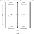
- the convex-concave lens 25, the doublet 26 and the plano-concave lens 29 cooperate to help maintain the far field radiation pattern as being generally constant regardless of the position of the combined laser beam in its scan pattern, as well as to properly shape the end-caps of the far field irradiation pattern, as shown in FIG. 2 . Furthermore, the convex-concave lens 25, the doublet 26 and the plano-concave lens 29 help limit the divergence of the combined laser beam along the axis of movement and help cause a high degree of divergence of the combined laser beam along the axis perpendicular to the axis of movement.
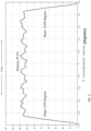
- FIG. 3 is a graph showing the vertical cross section of the combined laser beam (vertical cross section of the beam shown in FIG. 2 ) where it can be observed that the combined laser beam is generally top-hat shaped with a relatively flat top plateau.
- a graph showing the horizontal cross section of the combined laser beam (horizontal cross section of the beam shown in FIG. 2 ) is shown in FIG. 4 where it can observed that the combined laser beam has three peaks in its horizontal cross section (resulting from the multiple laser emitters used to form the combined laser beam).
- the resulting combined laser beam having the illustrated vertical and horizontal cross sections meets desired efficiency levels of over 90% with acceptable beam uniformity while properly passing through an exit window 31 without impinging on the interior of the housing 5 about the periphery of the exit window 31.
- a diffuser 30 is placed at the focal point within the housing 5. This diffuser 30 serves to improve the uniformity of the vertical cross section of the combined laser beam, but at the expense of efficiency.
- plano-concave lens 19, the lens doublet 20 and the concave-convex lens 23 may be removed if the optical path length is shortened, as shown in FIG. 6 , because shortening the optical path reduces the divergence along the axis of movement.
- the mirror 24 is immediately downstream of the folding mirror 18.
- the optical module 10 described above may be utilized in a light detection and ranging (LIDAR) system 50, as shown in FIG. 7 .
- a light detector 52 e.g., a light detector array
- a control circuitry 53 coupled to the light detector 52.
- a three-dimensional map of objects in the field of view can be formed by the control circuitry 53 and utilized by hardware external to the LIDAR system 50.
- the optical module serves to combine and focus multiple laser sources in a way so as to generate a combined laser beam that exhibits a low degree of divergence along an axis of movement of a uniaxial microelectromechanical system (MEMS) mirror located in the optical module, but exhibits a high degree of divergence along an axis perpendicular to the axis of movement.
- MEMS microelectromechanical system
- the resulting combined laser beam is relatively uniform and remains so as it is scanned along the axis of movement.
- the high divergence along the axis perpendicular to the axis of movement of the MEMS mirror permits the creation of a LIDAR system that utilizes one-dimensional scanning to form a three-dimensional map of a scene.
- Example 1 An optical module, comprising:
- Example 2 The optical module of Example 1, further comprising:
- Example 3 The optical module of Example 2, wherein the mirror is a uniaxial microelectromechanical (MEMS) mirror.
- MEMS microelectromechanical
- Example 4 The optical module of Example 1, further comprising a folding mirror downstream of the second lens doublet.
- Example 5 The optical module of Example 1, further comprising:
- Example 6 The optical module of Example 5, further comprising a mirror downstream of the convex-concave lens and upstream of the spherical lens, the mirror being operable to scan the combined laser beam along the second axis.
- Example 7 The optical module of Example 5, further comprising a diffuser downstream of the third lens doublet and upstream of the spherical lens, wherein the diffuser increases uniformity of a vertical cross section of the combined laser beam.
- Example 8 The optical module of Example 1, wherein the first lens doublet, second lens doublet, spherical lens, third lens doublet, and second plano-concave lens are carried within a housing, wherein the housing has an exit window formed therein; and wherein the combined laser beam passes through the exit window after exiting the second plano-concave lens without impinging upon surrounding portions of the housing.
- Example 9 An optical module for use in a light detection and ranging (LIDAR) device, the optical module comprising:
- Example 10 The optical module of Example 9, wherein the first lens comprises a first lens doublet; wherein the second lens comprises a second lens doublet; and wherein the fourth lens comprises a third lens doublet.
- Example 11 The optical module of Example 10, wherein the first lens doublet is comprised of a first plano-concave lens a first plano-convex lens downstream of the first plano-concave lens; wherein the second lens doublet is comprised of a first concave lens and first convex lens downstream of the first concave lens; and wherein the third lens doublet is comprised of a second concave lens, and a second convex lens downstream of the second concave lens.
- Example 12 The optical module of Example 11, wherein the third lens comprises a concave-convex lens; and wherein the fifth lens comprises a second plano-concave lens.
- Example 13 The optical module of Example 12, further comprising: a third plano-concave lens downstream of the folding mirror and upstream of the mirror; and a fourth lens doublet downstream of the third plano-concave lens and upstream of the mirror, the fourth lens doublet comprising: a second plano-convex lens and a concave-convex lens downstream of the third plano-concave lens; and a convex-concave lens downstream of the fourth lens doublet and upstream of the mirror.
- Example 14 The optical module of Example 9, further comprising a folding mirror downstream of the second lens and upstream of the third lens.
- Example 15 A method, comprising:
- Example 16 The method of Example 15, further comprising measuring an elapsed time between emission of a pulse of the combined laser beam and detection of photons of that pulse that have reflected off an object, and determining a distance to the object based upon the elapsed time.
- Example 17 The method of Example 15, wherein focusing the combined laser beam results in the combined laser beam having a vertical cross section that is generally plateaushaped with a flat top.
Landscapes
- Physics & Mathematics (AREA)
- General Physics & Mathematics (AREA)
- Optics & Photonics (AREA)
- Engineering & Computer Science (AREA)
- Computer Networks & Wireless Communication (AREA)
- Radar, Positioning & Navigation (AREA)
- Remote Sensing (AREA)
- Optical Radar Systems And Details Thereof (AREA)
- Semiconductor Lasers (AREA)
Abstract
Description
- The present invention relates to an optical module for a laser scanning projector, such as a laser scanning projector of a Light Detection and Ranging (LIDAR) system.
- A laser scanning projector is a small, portable electronic device. Laser scanning projectors may be paired to, or incorporated within, user devices such as smart glasses, head mounted displays, smartphones, tablets, or laptops, and used to project virtual and augmented reality, documents, images, or video stored on those user devices onto a projection surface, such as a wall, holographic surface, or inner display surface of virtual or augmented reality glasses (for example a wave guide in a coupling window).
- Laser scanning projectors are also incorporated within distance determination systems, such as LIDAR systems, within vehicles to determine information about the vehicles relative to their surroundings, permitting the creation of advanced driver assistance systems.
- In the case of a distance determination system, such laser scanning projectors typically include a projection system and an optical module. The optical module includes one or more laser sources and one or more microelectromechanical system (MEMS) mirrors that scan the laser beam produced by the one or more laser sources across the projection surface in a desired projection pattern. The projection system suitably drives the one or more laser sources such that distance determination can be performed by measuring the time between emission of a laser pulse emitted by the one or more laser sources and detection of photons of that laser pulse that have reflected off an object and been detected by a detector within the distance determination system. Given this time of flight and with the understanding of where the laser beam was scanned at any instant in time, a three-dimensional map of objects in the field of view of the distance determination system can be formed and utilized.
- Optical elements may be employed along the path of the laser beam between the one or more laser sources and the one or more MEMS mirrors so as to focus or collimate the laser beam in desired ways, and likewise may be employed between the one or more MEMS mirrors and an exit window so as to focus or further collimate the laser beam in desired ways.
- The projection pattern typically utilized in distance determination systems is a two-dimensional raster scan. This comes with certain challenges. For example, it may be difficult to keep the laser beam within an exit aperture as the laser beam is scanned in the projection pattern. Still further, it may be difficult to perform the two-dimensional raster scanning at a suitably fast enough rate for certain distance determination application.
- An aim of the invention is to overcome at least in part the problems of the prior art.
- According to the invention, an optical module and a method for forming a three-dimensional map of a scene are provided, as defined in the appended claims.
- In order to better understand the present invention, embodiments thereof will now be described, by way of mere non-limiting examples, with reference to the accompanying drawings, wherein:
-
FIG. 1 is a diagrammatical representation of a first embodiment of an optical module disclosed herein such as may be used in a distance determination system; -
FIG. 2 shows the combined far-field laser beam shape produced by the optical module ofFIG. 1 as three different points in the one-dimensional scan pattern utilized by the optical module; -
FIG. 3 is a graph showing the vertical cross section of the far field laser irradiance produced by the optical module ofFIG. 1 ; -
FIG. 4 is a graph showing the horizontal cross section of the far field laser irradiance produced by the optical module ofFIG. 1 ; -
FIG. 5 is a diagrammatical representation of a second embodiment of an optical module disclosed herein such as may be used in a distance determination system; -
FIG. 6 is a diagrammatical representation of a third embodiment of an optical module disclosed herein such as may be used in a distance determination system; -
FIG. 7 is a block diagram of a LIDAR system utilizing the optical module ofFIG. 1 . -
FIG. 1 shows anoptical module 10 for use in a laser scanning projector such as a LIDAR system. In general, the goal for theoptical module 10 is to generate a laser beam that exhibits a low degree of divergence along an axis of movement (e.g., horizontal axis, seeFIG. 2 ) of a uniaxial microelectromechanical system (MEMS)mirror 24 located in theoptical module 10, but exhibits a high degree of divergence along an axis (e.g., vertical axis, seeFIG. 2 ) perpendicular to the axis of movement in an efficient manner that permits the creation of a LIDAR system that utilizes laser scanning along the horizontal axis to form a three-dimensional map of a scene, thereby overcoming drawbacks of existing systems that are based upon two-dimensional raster scans. - The
optical module 10 includes alaser array 11 that is formed by multiple (e.g., eight) laser emitters within a single package, the eight laser emitters being arranged into an array such as a one-dimensional array, each laser emitter being formed, as an example, of multiple (e.g., three) laser cavities positioned close to one another. These laser emitters are each spaced such that the individual laser beams (e.g., infrared laser beams) generated by adjacent laser emitters overlap in part (e.g., the footprint of the individual laser beams is greater than the path divergence of those individual laser beams) to form a combined laser beam that has a generally pill-shaped cross section. The combined laser beam has a fast axis and a slow axis as understood by those of ordinary skill in the art. The fast axis is called the fast axis because the beam divergence is larger along the fast axis than the slow axis. Thus, as one moves away from thelaser array 10, the fast axis diameter grows at a faster rate than the diameter along the slow axis, and so it can be said that the laser beam diverges faster along its fast axis. The slow axis still diverges, however, the angle of divergence is smaller. - A
lens doublet 12 is located immediately (i.e., without the interposition of any other optical component) downstream (with respect to the optical path of the combined laser beam) of thelaser 11 and serves to focus the fast axis of the combined laser beam such that the divergence of the fast axis generally matches the divergence of the slow axis. As understood by those of skill in the art, a lens doublet is formed by two individual lensed bonded together at an interface. The lens doublet 12, in particular, is formed by a plano-concave lens 13 which has an upstream surface with a concave shaped cross section and a downstream surface with a planar cross section and a plano-convex lens 14 (e.g., a plano-cylinder lens) which has an upstream surface with a planar cross section and a downstream surface with a convex cross section. The plano-concave lens 13 and plano-convex lens 14 are bonded at the interface between the downstream planar surface of the plano-concave lens 13 and the upstream planar surface of the plano-convex lens 14. The downstream surface of the plano-concave lens 13 and the upstream surface of the plano-convex lens 14 may be matched. - A
lens doublet 15 is located immediately downstream of the first lens doublet 12 and serves to focus both the fast axis and the slow axis of the combined laser beam, although with this lens doublet 15 the focusing is slightly more focused along the slow axis. Thelens doublet 15 is formed by aconcave lens 16 having upstream and downstream surfaces that both have concave cross sections and aconvex lens 17 having upstream and downstream surfaces that both have convex cross sections. The downstream surface of theconvex lens 17 is generally paraboloid in shape to help correct for pupil aberrations. Theconcave lens 16 andconvex lens 17 are bonded at the interface between the downstream surface of theconcave lens 16 and the upstream surface of theconvex lens 17. - A folding mirror 18 (e.g., planar) is located immediately downstream of the second lens doublet 15 and serves to change the direction of travel of the combined laser beam. This function of the
folding mirror 18 is used to keep the physical space occupied by theoptical module 10 compact and fitting within ahousing 5. Thus, it will be appreciated by those of ordinary skill in the art that the use of the foldingmirror 18 is a matter of design choice and is optional. - A plano-concave lens 19 (e.g., a plano-cylinder lens) is located immediately downstream of the
folding mirror 18 and has an upstream surface with a planar cross section and a downstream surface with a concave cross section. - A lens doublet 20 (e.g., a spherical doublet) is located immediately downstream of the plano-
concave lens 19. Thelens doublet 20 is formed by a plano-convex lens 21 having an upstream surface with a planar cross section and a downstream surface with a convex cross section and a concave-convex lens 22 having an upstream surface with a concave cross section and a downstream surface with a convex cross section. The plano-convex lens 21 and concave-convex lens 22 are bonded at the interface between the downstream surface of the plano-convex lens 21 and the upstream surface of the concave-convex lens 22. The downstream surface of the plano-convex lens 21 and the upstream surface of the concave-convex lens 22 may be matched. - Collectively, the plano-
concave lens 19 andlens doublet 20 serve to help limit the divergence of the combined laser beam along the axis of movement while serving to help cause a high degree of divergence of the combined laser beam along the axis perpendicular to the axis of movement. - A concave-
convex lens 23 is arranged downstream of the lens doublet 20; furthermore, the concave-convex lens 23 has an upstream surface with a concave cross section and a downstream surface with a convex cross section. In particular, the concave-convex lens 23 may be a spherical singlet. - Due to the length of the optical path, a
focal point 35 occurs along the optical path between the lens doublet 20 and the concave-convex lens 23; in particular, the concave-convex lens 23 is immediately downstream of thefocal point 35. - The occurrence of this focal point could be eliminated by reducing the length of the optical path, although this focal point does not negatively impact operation because the
optical module 10 as shown inFIG. 1 is expressly designed to not have components placed at this focal point. Furthermore, this arrangement of the focal point helps provide theoptical module 10 with enhanced thermal stability in that the far field irradiation pattern formed by the combined laser beam remains generally constant over temperature and wavelength drifting. - A MEMS mirror 24 (e.g., planar), which may be operated at resonance, is located immediately downstream of the concave-
convex lens 23 and serves to scan the combined laser beam in a unidirectional scan pattern - for example, this scan pattern may be along the horizontal axis. - A convex-
concave lens 25 is located immediately downstream of theMEMS mirror 24 and has an upstream surface with a concave cross section and a downstream surface with a convex cross section. In particular, the convex-concave lens 25 may be a spherical singlet. - A lens doublet 26 (e.g., a spherical doublet) is located immediately downstream of the convex-
concave lens 25. Thedoublet 26 is formed by aconcave lens 27 which has upstream and downstream surfaces that both have concave cross sections and aconvex lens 28 that has upstream and downstream surfaces that both have convex cross sections. Theconcave lens 27 andconvex lens 28 are bonded at the interface between the downstream surface of theconcave lens 27 and the upstream surface of theconvex lens 28. - A plano-
concave lens 29 is located immediately downstream of thelens doublet 26 and has an upstream surface with a planar cross section and a downstream surface with a concave cross section. In particular, the plano-concave lens 29 may be a plano-cylinder lens. - The convex-
concave lens 25, thedoublet 26 and the plano-concave lens 29 cooperate to help maintain the far field radiation pattern as being generally constant regardless of the position of the combined laser beam in its scan pattern, as well as to properly shape the end-caps of the far field irradiation pattern, as shown inFIG. 2 . Furthermore, the convex-concave lens 25, thedoublet 26 and the plano-concave lens 29 help limit the divergence of the combined laser beam along the axis of movement and help cause a high degree of divergence of the combined laser beam along the axis perpendicular to the axis of movement. -
FIG. 3 is a graph showing the vertical cross section of the combined laser beam (vertical cross section of the beam shown inFIG. 2 ) where it can be observed that the combined laser beam is generally top-hat shaped with a relatively flat top plateau. A graph showing the horizontal cross section of the combined laser beam (horizontal cross section of the beam shown inFIG. 2 ) is shown inFIG. 4 where it can observed that the combined laser beam has three peaks in its horizontal cross section (resulting from the multiple laser emitters used to form the combined laser beam). Collectively, the resulting combined laser beam having the illustrated vertical and horizontal cross sections meets desired efficiency levels of over 90% with acceptable beam uniformity while properly passing through anexit window 31 without impinging on the interior of thehousing 5 about the periphery of theexit window 31. - In an alternate embodiment shown in
FIG. 5 , adiffuser 30 is placed at the focal point within thehousing 5. Thisdiffuser 30 serves to improve the uniformity of the vertical cross section of the combined laser beam, but at the expense of efficiency. - The plano-
concave lens 19, thelens doublet 20 and the concave-convex lens 23 may be removed if the optical path length is shortened, as shown inFIG. 6 , because shortening the optical path reduces the divergence along the axis of movement. Here, themirror 24 is immediately downstream of thefolding mirror 18. - The
optical module 10 described above may be utilized in a light detection and ranging (LIDAR)system 50, as shown inFIG. 7 . A light detector 52 (e.g., a light detector array) is added so that the time between emission of a pulse of the laser and detection of photons of that laser pulse that have reflected off an object and been detected by thelight detector 52 can be determined by acontrol circuitry 53 coupled to thelight detector 52. Given this time of flight and with the understanding of where the laser beam was scanned at any instant in time, a three-dimensional map of objects in the field of view can be formed by thecontrol circuitry 53 and utilized by hardware external to theLIDAR system 50. - The advantages that the present solution allows obtaining clearly emerge from the preceding description. In particular, the optical module serves to combine and focus multiple laser sources in a way so as to generate a combined laser beam that exhibits a low degree of divergence along an axis of movement of a uniaxial microelectromechanical system (MEMS) mirror located in the optical module, but exhibits a high degree of divergence along an axis perpendicular to the axis of movement. The resulting combined laser beam is relatively uniform and remains so as it is scanned along the axis of movement. The high divergence along the axis perpendicular to the axis of movement of the MEMS mirror permits the creation of a LIDAR system that utilizes one-dimensional scanning to form a three-dimensional map of a scene.
- Finally, it is clear that modifications and variations may be made to what has been described and illustrated herein, without thereby departing from the scope of this disclosure, as defined in the annexed claims.
- Example embodiments of the present invention are summarized here.
- Example 1. An optical module, comprising:
- a first lens doublet receiving a combined laser beam, the first lens doublet comprising:
a first plano-concave lens having an upstream surface with a concave cross section and a downstream surface with a planar cross section, and a first plano-convex lens downstream of the first plano-concave lens having an upstream surface with a planar cross section and a downstream surface with a convex cross section; - a second lens doublet downstream of the first lens doublet and comprising: a first concave lens, and a second lens downstream of the first concave lens having an upstream surface with a convex cross section and a downstream surface with a paraboloid cross section;
- a spherical lens downstream of the second lens doublet and having an upstream surface with a concave cross section and a downstream surface with a convex cross section;
- a third lens doublet downstream of the spherical lens and comprising: a second concave lens, and a convex lens downstream of the second concave lens; and
- a second plano-concave lens having an upstream surface with a planar cross section and a downstream surface with a concave cross section;
- wherein the first lens doublet, second lens doublet, spherical lens, third lens doublet, and second plano-concave lens cooperate to shape the combined laser beam to have high-divergence along a first axis but low-divergence along a second axis.
- Example 2. The optical module of Example 1, further comprising:
- a laser array comprised of a plurality of laser emitters arranged into a line and spaced apart from one another such that individual laser beams generated by adjacent laser emitters of the plurality of laser emitters at least partially overlap so that the combined laser beam is produced by the laser array; and
- a mirror downstream of the second lens doublet and upstream of the spherical lens, the mirror being operable to scan the combined laser beam along the second axis.
- Example 3. The optical module of Example 2, wherein the mirror is a uniaxial microelectromechanical (MEMS) mirror.
- Example 4. The optical module of Example 1, further comprising a folding mirror downstream of the second lens doublet.
- Example 5. The optical module of Example 1, further comprising:
- a third plano-concave lens downstream of the second lens doublet and upstream of the spherical lens, the third plano-concave lens having an upstream surface with a planar cross section and a downstream surface with a concave cross section;
- a fourth lens doublet downstream of the third plano-concave lens and upstream of the spherical lens, the fourth lens doublet comprising: a second plano-convex lens having an upstream surface with a planar cross section and a downstream surface with a convex cross section, and a concave-convex lens downstream of the third plano-concave lens and having an upstream surface with a concave cross section and a downstream surface with a convex cross section; and
- a convex-concave lens downstream of the fourth lens doublet and upstream of the spherical lens, the convex-concave lens having an upstream surface with a concave cross section and a downstream surface with a convex cross section.
- Example 6. The optical module of Example 5, further comprising a mirror downstream of the convex-concave lens and upstream of the spherical lens, the mirror being operable to scan the combined laser beam along the second axis.
- Example 7. The optical module of Example 5, further comprising a diffuser downstream of the third lens doublet and upstream of the spherical lens, wherein the diffuser increases uniformity of a vertical cross section of the combined laser beam.
- Example 8. The optical module of Example 1, wherein the first lens doublet, second lens doublet, spherical lens, third lens doublet, and second plano-concave lens are carried within a housing, wherein the housing has an exit window formed therein; and wherein the combined laser beam passes through the exit window after exiting the second plano-concave lens without impinging upon surrounding portions of the housing.
- Example 9. An optical module for use in a light detection and ranging (LIDAR) device, the optical module comprising:
- a laser array comprised of a plurality of laser emitters arranged into a line and spaced apart from one another such that individual laser beams generated by adjacent laser emitters of the plurality of laser emitters at least partially overlap so that a combined laser beam is produced by the laser array;
- a first lens configured to receive the combined laser beam and focus a fast axis thereof;
- a second lens downstream of the first lens and configured to focus a slow axis of the combined laser beam, wherein a cross section of the combined laser beam as the combined laser beam exits the second lens is generally pill shaped;
- a mirror downstream of the second lens, the mirror being operable to scan the combined laser beam along a second axis;
- a third lens downstream of the mirror, a fourth lens downstream of the third lens, and a fifth lens downstream of the fourth lens, wherein the first lens, second lens, and third lens cooperate to maintain a shape of the combined laser beam as being consistent as the mirror scans the combined laser beam along the second axis; and
- a housing carrying the laser array, first lens, second lens, mirror, third lens, fourth lens, and fifth lens, the housing having an exit window formed therein, wherein the combined laser beam passes through the exit window after exiting the fifth lens without impinging upon surrounding portions of the housing;
- wherein the first lens, second lens, third lens, fourth lens, and fifth lens cooperate to shape the combined laser beam to have high-divergence along a first axis but low-divergence along the second axis .
- Example 10. The optical module of Example 9, wherein the first lens comprises a first lens doublet; wherein the second lens comprises a second lens doublet; and wherein the fourth lens comprises a third lens doublet.
- Example 11. The optical module of Example 10, wherein the first lens doublet is comprised of a first plano-concave lens a first plano-convex lens downstream of the first plano-concave lens; wherein the second lens doublet is comprised of a first concave lens and first convex lens downstream of the first concave lens; and wherein the third lens doublet is comprised of a second concave lens, and a second convex lens downstream of the second concave lens.
- Example 12. The optical module of Example 11, wherein the third lens comprises a concave-convex lens; and wherein the fifth lens comprises a second plano-concave lens.
- Example 13. The optical module of Example 12, further comprising: a third plano-concave lens downstream of the folding mirror and upstream of the mirror; and a fourth lens doublet downstream of the third plano-concave lens and upstream of the mirror, the fourth lens doublet comprising: a second plano-convex lens and a concave-convex lens downstream of the third plano-concave lens; and a convex-concave lens downstream of the fourth lens doublet and upstream of the mirror.
- Example 14. The optical module of Example 9, further comprising a folding mirror downstream of the second lens and upstream of the third lens.
- Example 15. A method, comprising:
- generating a combined laser beam by generating multiple individual laser beams sufficiently close to one another such that adjacent ones of the individual laser beams at least partially overlap;
- focusing the combined laser beam so as to have a substantially greater divergence along a vertical axis than along a horizontal axis; and
- receiving the combined laser beam at a micromirror and scanning the combined laser beam along the horizontal axis using the micromirror, wherein the focusing of the combined laser beam is such that it fits through an exit aperture as it is scanned along the horizontal axis without impinging upon a housing into which the exit aperture is defined and such that it remains relatively uniform and homogenous as it is scanned along the horizontal axis.
- Example 16. The method of Example 15, further comprising measuring an elapsed time between emission of a pulse of the combined laser beam and detection of photons of that pulse that have reflected off an object, and determining a distance to the object based upon the elapsed time.
- Example 17. The method of Example 15, wherein focusing the combined laser beam results in the combined laser beam having a vertical cross section that is generally plateaushaped with a flat top.
Claims (11)
- An optical module for a laser scanning projector, comprising:- a first lens doublet (12) configured to receive a combined laser beam, the first lens doublet comprising: a first plano-concave lens (13) having an upstream surface with a concave cross section and a downstream surface with a planar cross section, and a first plano-convex lens (14) downstream of the first plano-concave lens (13) having an upstream surface with a planar cross section and a downstream surface with a convex cross section;- a second lens doublet (15) downstream of the first lens doublet (12) and comprising:
a first concave lens (16), and a second lens (17) downstream of the first concave lens (16) having an upstream surface with a convex cross section and a downstream surface with a paraboloid cross section;- a spherical lens (25) downstream of the second lens doublet (15) and having an upstream surface with a concave cross section and a downstream surface with a convex cross section;- a third lens doublet downstream (26) of the spherical lens (25) and comprising: a second concave lens (27) and a convex lens (28) downstream of the second concave lens (27); and- a second plano-concave lens (29) having an upstream surface with a planar cross section and a downstream surface with a concave cross section;wherein the first lens doublet (12), the second lens doublet (15), the spherical lens (25), the third lens doublet (26) and the second plano-concave lens (29) cooperate to shape the combined laser beam to have high-divergence along a first axis and a low-divergence along a second axis. - The optical module of claim 1, further comprising a mirror (24) downstream of the second lens doublet (15) and upstream of the spherical lens (25), the mirror (24) being operable to scan the combined laser beam along the second axis.
- The optical module of claim 2, wherein the mirror (24) is a uniaxial microelectromechanical (MEMS) mirror.
- The optical module of claim 2 or 3, further comprising:- a third plano-concave lens (19) downstream of the second lens doublet (15) and upstream of the spherical lens (25), the third plano-concave lens (19) having an upstream surface with a planar cross section and a downstream surface with a concave cross section;- a fourth lens doublet (20) downstream of the third plano-concave lens (19) and upstream of the spherical lens (25), the fourth lens doublet (20) comprising: a second plano-convex lens (21) having an upstream surface with a planar cross section and a downstream surface with a convex cross section, and a concave-convex lens (22) downstream of the third plano-concave lens (19) and having an upstream surface with a concave cross section and a downstream surface with a convex cross section; and- a convex-concave lens (23) downstream of the fourth lens doublet (20) and upstream of the mirror (24), the convex-concave lens (23) having an upstream surface with a concave cross section and a downstream surface with a convex cross section.
- The optical module of claim 4, further comprising a diffuser (30) downstream of the fourth lens doublet (20) and upstream of the convex-concave lens (23), wherein the diffuser (30) is configured to increase the uniformity of a cross section of the combined laser beam along the first axis.
- The optical module according to any of the preceding claims, further comprising a housing (5); and wherein the first lens doublet (12), the second lens doublet (15), the spherical lens (25), the third lens doublet (26), and the second plano-concave lens (29) are arranged within the housing (5), wherein the housing (5) has an exit window (31); and wherein the combined laser beam passes through the exit window (31) after exiting the second plano-concave lens (29) without impinging on the housing (5), during the scanning.
- The optical module according to any of the preceding claims, further comprising a folding mirror (18) downstream of the second lens doublet (15).
- The optical module according to any of the preceding claims, further comprising:- a laser array (11) comprising a plurality of laser emitters arranged into a line and spaced apart from one another such that individual laser beams generated by adjacent laser emitters of the plurality of laser emitters at least partially overlap so that a combined laser beam is produced by the laser array (11).
- The optical module according to claim 8, wherein:- the first lens doublet (12) is configured to receive the combined laser beam and focus a fast axis thereof;- the second lens doublet (15) is configured to focus a slow axis of the combined laser beam, wherein a cross section of the combined laser beam as the combined laser beam exits the second lens is generally pill shaped.
- A method for forming a three-dimensional map of a scene, comprising:- generating, through the optical module (10) according to any of the preceding claims, the combined laser beam;- measuring an elapsed time between emission of a pulse of the combined laser beam and detection of photons of that pulse that have reflected off an object, and determining a distance to the object based upon the elapsed time.
- The method according to claim 10, wherein generating the combined laser beam results in the combined laser beam having a vertical cross section that is generally plateaushaped with a flat top.
Applications Claiming Priority (1)
| Application Number | Priority Date | Filing Date | Title |
|---|---|---|---|
| US17/711,780 US12416802B2 (en) | 2022-04-01 | 2022-04-01 | Scanner laser optics for LIDAR |
Publications (1)
| Publication Number | Publication Date |
|---|---|
| EP4254050A1 true EP4254050A1 (en) | 2023-10-04 |
Family
ID=85704649
Family Applications (1)
| Application Number | Title | Priority Date | Filing Date |
|---|---|---|---|
| EP23162790.2A Withdrawn EP4254050A1 (en) | 2022-04-01 | 2023-03-20 | Optical module for a laser scanning projector |
Country Status (3)
| Country | Link |
|---|---|
| US (1) | US12416802B2 (en) |
| EP (1) | EP4254050A1 (en) |
| CN (2) | CN116893506A (en) |
Families Citing this family (1)
| Publication number | Priority date | Publication date | Assignee | Title |
|---|---|---|---|---|
| US12416802B2 (en) | 2022-04-01 | 2025-09-16 | Stmicroelectronics International N.V. | Scanner laser optics for LIDAR |
Citations (5)
| Publication number | Priority date | Publication date | Assignee | Title |
|---|---|---|---|---|
| EP0396128A2 (en) * | 1989-05-03 | 1990-11-07 | Hughes Aircraft Company | Catadioptric projector, catadioptric projection system and process |
| US20050063428A1 (en) * | 2003-09-22 | 2005-03-24 | Anikitchev Serguei G. | Apparatus for projecting a line of light from a diode-laser array |
| US20120057345A1 (en) * | 2010-09-07 | 2012-03-08 | Coherent, Inc. | Line-projection apparatus for arrays of diode-laser bar stacks |
| US20180167602A1 (en) * | 2015-09-24 | 2018-06-14 | Ouster, Inc. | Optical system for collecting distance information within a field |
| US20190162858A1 (en) * | 2017-11-30 | 2019-05-30 | Cepton Technologies, Inc. | Detector designs for improved resolution in lidar systems |
Family Cites Families (8)
| Publication number | Priority date | Publication date | Assignee | Title |
|---|---|---|---|---|
| JP2007178727A (en) | 2005-12-28 | 2007-07-12 | Seiko Epson Corp | Lighting device and projector |
| JP2019164284A (en) | 2018-03-20 | 2019-09-26 | 日本電産コパル電子株式会社 | Scanning optical device |
| US10725180B2 (en) | 2018-03-26 | 2020-07-28 | Rosemount Aerospace Inc. | Array of independently-controllable laser diode bars for scanning a linear illumination pattern |
| US11875714B2 (en) | 2018-09-14 | 2024-01-16 | Apple Inc. | Scanning display systems |
| WO2021240978A1 (en) | 2020-05-29 | 2021-12-02 | パナソニックIpマネジメント株式会社 | Beam scanning optical system and laser radar |
| US20230045982A1 (en) * | 2021-08-11 | 2023-02-16 | Vergent Research Pty Ltd | Shuttered Light Field Display |
| US12405457B2 (en) * | 2022-03-21 | 2025-09-02 | Stmicroelectronics International N.V. | Reflective pupil relay optics for mems scanning system |
| US12416802B2 (en) | 2022-04-01 | 2025-09-16 | Stmicroelectronics International N.V. | Scanner laser optics for LIDAR |
-
2022
- 2022-04-01 US US17/711,780 patent/US12416802B2/en active Active
-
2023
- 2023-03-20 EP EP23162790.2A patent/EP4254050A1/en not_active Withdrawn
- 2023-03-31 CN CN202310338309.0A patent/CN116893506A/en active Pending
- 2023-03-31 CN CN202320690915.4U patent/CN220105417U/en active Active
Patent Citations (5)
| Publication number | Priority date | Publication date | Assignee | Title |
|---|---|---|---|---|
| EP0396128A2 (en) * | 1989-05-03 | 1990-11-07 | Hughes Aircraft Company | Catadioptric projector, catadioptric projection system and process |
| US20050063428A1 (en) * | 2003-09-22 | 2005-03-24 | Anikitchev Serguei G. | Apparatus for projecting a line of light from a diode-laser array |
| US20120057345A1 (en) * | 2010-09-07 | 2012-03-08 | Coherent, Inc. | Line-projection apparatus for arrays of diode-laser bar stacks |
| US20180167602A1 (en) * | 2015-09-24 | 2018-06-14 | Ouster, Inc. | Optical system for collecting distance information within a field |
| US20190162858A1 (en) * | 2017-11-30 | 2019-05-30 | Cepton Technologies, Inc. | Detector designs for improved resolution in lidar systems |
Non-Patent Citations (1)
| Title |
|---|
| DETER C ET AL: "HIGH RESOLUTION SCANNING LASER PROJECTION DISPLAY WITH DIODE PUMPED SOLID STATE LASERS", 20000124, vol. 3954, 24 January 2000 (2000-01-24), pages 175 - 184, XP009001761, DOI: 10.1117/12.383370 * |
Also Published As
| Publication number | Publication date |
|---|---|
| US12416802B2 (en) | 2025-09-16 |
| US20230314791A1 (en) | 2023-10-05 |
| CN220105417U (en) | 2023-11-28 |
| CN116893506A (en) | 2023-10-17 |
Similar Documents
| Publication | Publication Date | Title |
|---|---|---|
| US11764539B2 (en) | Transmitting device for a LIDAR scanner having a scanning mirror covered by a cover element | |
| US12332381B2 (en) | 3D sensing | |
| US11592530B2 (en) | Detector designs for improved resolution in lidar systems | |
| US20140078473A1 (en) | Scanning type projector | |
| US10114215B1 (en) | Scanning laser devices with reduced exit pupil disparity | |
| US10001583B2 (en) | Structured light projection using a compound patterned mask | |
| US11598965B2 (en) | Super-resolution scanning display for near-eye displays | |
| US10754234B2 (en) | Projection device | |
| CN220569012U (en) | Optical system and optical module | |
| CN103477279A (en) | Free form optical redirection apparatus | |
| CN116583776B (en) | Optical detection device | |
| US12416802B2 (en) | Scanner laser optics for LIDAR | |
| CN112684464B (en) | Apparatus and method for projecting laser line and light detection ranging apparatus | |
| US20210333405A1 (en) | Lidar projection apparatus | |
| CN109283540B (en) | System and optical path structure suitable for outputting patterned light beam | |
| CN110940960B (en) | Laser radar scanning system and laser radar scanning method | |
| CN110456327B (en) | Laser radar receiving device and laser radar system | |
| CN113126460A (en) | Laser scanning unit | |
| JP2021184009A (en) | Image projection device | |
| US20250237747A1 (en) | Anamorphic beam transformation to match a lidar scanner | |
| US20220140571A1 (en) | Compact optical module | |
| CN121209122A (en) | 3D display device | |
| JP2021144131A (en) | Display device and mobile body | |
| CN116087985A (en) | Variable field scanning system and method thereof |
Legal Events
| Date | Code | Title | Description |
|---|---|---|---|
| PUAI | Public reference made under article 153(3) epc to a published international application that has entered the european phase |
Free format text: ORIGINAL CODE: 0009012 |
|
| STAA | Information on the status of an ep patent application or granted ep patent |
Free format text: STATUS: THE APPLICATION HAS BEEN PUBLISHED |
|
| AK | Designated contracting states |
Kind code of ref document: A1 Designated state(s): AL AT BE BG CH CY CZ DE DK EE ES FI FR GB GR HR HU IE IS IT LI LT LU LV MC ME MK MT NL NO PL PT RO RS SE SI SK SM TR |
|
| STAA | Information on the status of an ep patent application or granted ep patent |
Free format text: STATUS: REQUEST FOR EXAMINATION WAS MADE |
|
| 17P | Request for examination filed |
Effective date: 20240326 |
|
| RBV | Designated contracting states (corrected) |
Designated state(s): AL AT BE BG CH CY CZ DE DK EE ES FI FR GB GR HR HU IE IS IT LI LT LU LV MC ME MK MT NL NO PL PT RO RS SE SI SK SM TR |
|
| REG | Reference to a national code |
Ref country code: DE Ref legal event code: R079 Free format text: PREVIOUS MAIN CLASS: G02B0027090000 Ipc: G02B0026100000 |
|
| RIC1 | Information provided on ipc code assigned before grant |
Ipc: G02B 26/10 20060101AFI20251126BHEP |
|
| GRAP | Despatch of communication of intention to grant a patent |
Free format text: ORIGINAL CODE: EPIDOSNIGR1 |
|
| STAA | Information on the status of an ep patent application or granted ep patent |
Free format text: STATUS: GRANT OF PATENT IS INTENDED |
|
| STAA | Information on the status of an ep patent application or granted ep patent |
Free format text: STATUS: THE APPLICATION HAS BEEN WITHDRAWN |
|
| INTG | Intention to grant announced |
Effective date: 20260102 |
|
| RIN1 | Information on inventor provided before grant (corrected) |
Inventor name: SCHMIDT, JACK Inventor name: NESTOROVIC, NENAD |
|
| 18W | Application withdrawn |
Effective date: 20260109 |