EP4253895A1 - Heat exchanger and refrigeration cycle device - Google Patents
Heat exchanger and refrigeration cycle device Download PDFInfo
- Publication number
- EP4253895A1 EP4253895A1 EP20963562.2A EP20963562A EP4253895A1 EP 4253895 A1 EP4253895 A1 EP 4253895A1 EP 20963562 A EP20963562 A EP 20963562A EP 4253895 A1 EP4253895 A1 EP 4253895A1
- Authority
- EP
- European Patent Office
- Prior art keywords
- fin
- heat exchanger
- protruding portion
- protruding
- longitudinal direction
- Prior art date
- Legal status (The legal status is an assumption and is not a legal conclusion. Google has not performed a legal analysis and makes no representation as to the accuracy of the status listed.)
- Withdrawn
Links
Images






Classifications
-
- F—MECHANICAL ENGINEERING; LIGHTING; HEATING; WEAPONS; BLASTING
- F28—HEAT EXCHANGE IN GENERAL
- F28F—DETAILS OF HEAT-EXCHANGE AND HEAT-TRANSFER APPARATUS, OF GENERAL APPLICATION
- F28F1/00—Tubular elements; Assemblies of tubular elements
- F28F1/10—Tubular elements and assemblies thereof with means for increasing heat-transfer area, e.g. with fins, with projections, with recesses
- F28F1/12—Tubular elements and assemblies thereof with means for increasing heat-transfer area, e.g. with fins, with projections, with recesses the means being only outside the tubular element
- F28F1/24—Tubular elements and assemblies thereof with means for increasing heat-transfer area, e.g. with fins, with projections, with recesses the means being only outside the tubular element and extending transversely
- F28F1/32—Tubular elements and assemblies thereof with means for increasing heat-transfer area, e.g. with fins, with projections, with recesses the means being only outside the tubular element and extending transversely the means having portions engaging further tubular elements
- F28F1/325—Fins with openings
-
- F—MECHANICAL ENGINEERING; LIGHTING; HEATING; WEAPONS; BLASTING
- F28—HEAT EXCHANGE IN GENERAL
- F28D—HEAT-EXCHANGE APPARATUS, NOT PROVIDED FOR IN ANOTHER SUBCLASS, IN WHICH THE HEAT-EXCHANGE MEDIA DO NOT COME INTO DIRECT CONTACT
- F28D1/00—Heat-exchange apparatus having stationary conduit assemblies for one heat-exchange medium only, the media being in contact with different sides of the conduit wall, in which the other heat-exchange medium is a large body of fluid, e.g. domestic or motor car radiators
- F28D1/02—Heat-exchange apparatus having stationary conduit assemblies for one heat-exchange medium only, the media being in contact with different sides of the conduit wall, in which the other heat-exchange medium is a large body of fluid, e.g. domestic or motor car radiators with heat-exchange conduits immersed in the body of fluid
- F28D1/04—Heat-exchange apparatus having stationary conduit assemblies for one heat-exchange medium only, the media being in contact with different sides of the conduit wall, in which the other heat-exchange medium is a large body of fluid, e.g. domestic or motor car radiators with heat-exchange conduits immersed in the body of fluid with tubular conduits
- F28D1/047—Heat-exchange apparatus having stationary conduit assemblies for one heat-exchange medium only, the media being in contact with different sides of the conduit wall, in which the other heat-exchange medium is a large body of fluid, e.g. domestic or motor car radiators with heat-exchange conduits immersed in the body of fluid with tubular conduits the conduits being bent, e.g. in a serpentine or zig-zag
- F28D1/0477—Heat-exchange apparatus having stationary conduit assemblies for one heat-exchange medium only, the media being in contact with different sides of the conduit wall, in which the other heat-exchange medium is a large body of fluid, e.g. domestic or motor car radiators with heat-exchange conduits immersed in the body of fluid with tubular conduits the conduits being bent, e.g. in a serpentine or zig-zag the conduits being bent in a serpentine or zig-zag
-
- F—MECHANICAL ENGINEERING; LIGHTING; HEATING; WEAPONS; BLASTING
- F28—HEAT EXCHANGE IN GENERAL
- F28F—DETAILS OF HEAT-EXCHANGE AND HEAT-TRANSFER APPARATUS, OF GENERAL APPLICATION
- F28F1/00—Tubular elements; Assemblies of tubular elements
- F28F1/10—Tubular elements and assemblies thereof with means for increasing heat-transfer area, e.g. with fins, with projections, with recesses
- F28F1/12—Tubular elements and assemblies thereof with means for increasing heat-transfer area, e.g. with fins, with projections, with recesses the means being only outside the tubular element
- F28F1/24—Tubular elements and assemblies thereof with means for increasing heat-transfer area, e.g. with fins, with projections, with recesses the means being only outside the tubular element and extending transversely
- F28F1/32—Tubular elements and assemblies thereof with means for increasing heat-transfer area, e.g. with fins, with projections, with recesses the means being only outside the tubular element and extending transversely the means having portions engaging further tubular elements
-
- F—MECHANICAL ENGINEERING; LIGHTING; HEATING; WEAPONS; BLASTING
- F28—HEAT EXCHANGE IN GENERAL
- F28F—DETAILS OF HEAT-EXCHANGE AND HEAT-TRANSFER APPARATUS, OF GENERAL APPLICATION
- F28F17/00—Removing ice or water from heat-exchange apparatus
- F28F17/005—Means for draining condensates from heat exchangers, e.g. from evaporators
-
- F—MECHANICAL ENGINEERING; LIGHTING; HEATING; WEAPONS; BLASTING
- F28—HEAT EXCHANGE IN GENERAL
- F28F—DETAILS OF HEAT-EXCHANGE AND HEAT-TRANSFER APPARATUS, OF GENERAL APPLICATION
- F28F19/00—Preventing the formation of deposits or corrosion, e.g. by using filters or scrapers
- F28F19/006—Preventing deposits of ice
-
- F—MECHANICAL ENGINEERING; LIGHTING; HEATING; WEAPONS; BLASTING
- F28—HEAT EXCHANGE IN GENERAL
- F28D—HEAT-EXCHANGE APPARATUS, NOT PROVIDED FOR IN ANOTHER SUBCLASS, IN WHICH THE HEAT-EXCHANGE MEDIA DO NOT COME INTO DIRECT CONTACT
- F28D21/00—Heat-exchange apparatus not covered by any of the groups F28D1/00 - F28D20/00
- F28D2021/0019—Other heat exchangers for particular applications; Heat exchange systems not otherwise provided for
- F28D2021/0068—Other heat exchangers for particular applications; Heat exchange systems not otherwise provided for for refrigerant cycles
-
- F—MECHANICAL ENGINEERING; LIGHTING; HEATING; WEAPONS; BLASTING
- F28—HEAT EXCHANGE IN GENERAL
- F28F—DETAILS OF HEAT-EXCHANGE AND HEAT-TRANSFER APPARATUS, OF GENERAL APPLICATION
- F28F2225/00—Reinforcing means
- F28F2225/06—Reinforcing means for fins
Definitions
- the present disclosure relates to a heat exchanger and a refrigeration cycle apparatus.
- a fin-and-tube-type heat exchanger including a fin and a heat transfer tube passing through the fin.
- a fin includes a seat portion (planar portion), and peak and valley portions.
- the seat portion is concentrically formed around an outer circumference of a fin collar to guide air flowing around a heat transfer tube to thereby reduce a wake region.
- the seat portion is provided with opened front and rear portions.
- the peak and valley portions are continuously formed between the fin collars to provide airflow variation.
- the peak and valley portions are continuously formed along an air flow direction, and thus, a boundary layer starting from the peak portion is formed. Therefore, the valley portion forms a dead water region. As a result, a local heat transfer coefficient in the valley portion decreases, which leads to a decrease in heat transfer coefficient of the entire fin. In addition, stress concentrates on the planar portion provided with no peak and valley portions, and thus, the fin has insufficient strength.
- An object of the present disclosure is to provide a heat exchanger and a refrigeration cycle apparatus that can improve a heat transfer efficiency and improve a strength of a fin.
- a heat exchanger of the present disclosure includes: a fin extending in a widthwise direction along an air flow direction and extending in a longitudinal direction crossing the air flow direction; and a heat transfer tube passing through the fin.
- the fin has a through hole.
- the heat transfer tube is inserted into the through hole.
- the fin includes a planar portion, and a first protruding portion and a second protruding portion protruding from the planar portion.
- the first protruding portion is curved along the longitudinal direction.
- the second protruding portion has an extending portion extending in the longitudinal direction. The extending portion is located to overlap a center of the through hole in the widthwise direction.
- the first protruding portion and the second protruding portion protrude from the planar portion, and thus, an influence of a dead water region can be suppressed. Therefore, an improvement in heat transfer coefficient of the fin can be achieved. Also, the strength of the fin can be improved by the first protruding portion and the second protruding portion.
- a configuration of a heat exchanger HE according to a first embodiment will be described with reference to Figs. 1 to 4 .
- heat exchanger HE includes a fin F and a heat transfer tube P.
- Fin F extends in a widthwise direction D1 along an air flow direction D0 and extends in a longitudinal direction D2 crossing air flow direction D0.
- Fin F is formed in a substantially rectangular shape.
- Heat transfer tube P passes through fin F.
- Heat transfer tube P is a circular pipe.
- Fin F has a through hole TH. Through hole TH is formed in a circular shape. Heat transfer tube P is inserted into through hole TH.
- heat exchanger HE includes a plurality of fins F.
- the plurality of fins F are stacked on top of each other at intervals.
- Heat transfer tube P passes through the plurality of fins F in a direction D3 in which the plurality of fins F are stacked.
- Each of the plurality of fins F has a plurality of through holes TH.
- the plurality of through holes TH are aligned in longitudinal direction D2 of fin F.
- the plurality of through holes TH are spaced apart from each other in longitudinal direction D2 of fin F.
- Widthwise direction D1 of fin F is orthogonal to longitudinal direction D2. Widthwise direction D1 of fin F may be a horizontal direction. Longitudinal direction D2 of fin F may be an up-down direction (vertical direction). Direction D3 in which fins F are stacked is orthogonal to widthwise direction D1 and longitudinal direction D2 of fin F.
- Heat transfer tube P has a plurality of heat transfer portions P1 and a plurality of connection portions P2. Each of the plurality of heat transfer portions P1 passes through the plurality of fins F. Each of the plurality of heat transfer portions P1 is inserted into the plurality of through holes TH in direction D3 in which the plurality of fins F are stacked. The plurality of heat transfer portions P1 are formed linearly. Each of the plurality of heat transfer portions P1 extends in direction D3 in which the plurality of fins F are stacked.
- Each of the plurality of connection portions P2 is a portion that connects corresponding heat transfer portions P1 of the plurality of heat transfer portions P1 outside the plurality of fins F.
- Each of the plurality of connection portions P2 is formed in a U-shape.
- Each of the plurality of connection portions P2 connects heat transfer tubes P adjacent to each other in longitudinal direction D2 of fin F.
- Each of the plurality of connection portions P2 is connected to ends of heat transfer portions P1 in direction D3 in which fins F are stacked.
- the plurality of heat transfer portions P1 are located at a plurality of stages in longitudinal direction D2 of fin F. In the present embodiment, the plurality of heat transfer portions P1 are located at four stages along longitudinal direction D2 of fin F.
- the plurality of heat transfer portions P1 are connected by the plurality of connection portions P2 as follows.
- Heat transfer portion P1 in the first stage is connected to heat transfer portion P1 in the second stage by connection portion P2 on the back side in direction D3 in which the plurality of fins F are stacked.
- Heat transfer portion P1 in the second stage is connected to heat transfer portion P1 in the third stage by connection portion P2 on the front side in direction D3 in which the plurality of fins F are stacked.
- Heat transfer portion P1 in the third stage is connected to heat transfer portion P1 in the fourth stage by connection portion P2 on the back side in direction D3 in which the plurality of fins F are stacked.
- heat transfer tube P is configured to meander in longitudinal direction D2 of fin F.
- Fin F includes a planar portion SP, a first protruding portion MP1, a second protruding portion MP2, and a fin collar FC.
- Planar portion SP is formed in a planar shape.
- Planar portion SP is formed in a flat plate shape.
- First protruding portion MP1 and second protruding portion MP2 protrude from planar portion SP.
- first protruding portion MP1 and second protruding portion MP2 protrude from planar portion SP in the same direction.
- fin F includes a plurality of first protruding portions MP1 and a plurality of second protruding portions MP2.
- First protruding portion MP1 is curved along longitudinal direction D2 of fin F. First protruding portion MP1 is curved to protrude in longitudinal direction D2 of fin F. First protruding portion MP1 has a portion extending along longitudinal direction D2 of fin F. First protruding portion MP1 also has a portion extending along widthwise direction D1 of fin F. First protruding portion MP1 is located to be displaced from the center of through hole TH in widthwise direction D1 of fin F. In the present embodiment, first protruding portion MP1 is formed in a circular arc shape. In the present embodiment, first protruding portions MP1 have the same width.
- the plurality of first protruding portions MP1 are aligned in longitudinal direction D2 of fin F.
- First protruding portions MP1 are spaced apart from each other in longitudinal direction D2 of fin F.
- two first protruding portions MP1 are located between two through holes TH in longitudinal direction D2 of fin F.
- Two first protruding portions MP1 are located to face each other in longitudinal direction D2 of fin F.
- First protruding portions MP1 facing each other are curved to protrude toward each other.
- First protruding portions MP1 are formed in the same shape except for the direction in which first protruding portions MP1 are curved along longitudinal direction D2 of fin F. First protruding portions MP1 have the same radius of curvature. The respective centers of curvature of first protruding portions MP1 are linearly aligned with each other in longitudinal direction D2 of fin F. First protruding portions MP1 have the same width. First protruding portions MP1 have the same length.
- Each of the plurality of first protruding portions MP1 is longer than each of the plurality of second protruding portions MP2 in widthwise direction D1 of fin F.
- each of the plurality of first protruding portions MP1 is located between corresponding ones of the plurality of second protruding portions MP2.
- the respective centers of curvature of the plurality of first protruding portions MP1 are linearly aligned with the respective centers of the plurality of second protruding portions MP2 in longitudinal direction D2 of fin F.
- Second protruding portion MP2 has an extending portion EP extending in longitudinal direction D2 of fin F. Second protruding portion MP2 has a portion extending along longitudinal direction D2 of fin F. Extending portion EP is located to overlap the center of through hole TH in widthwise direction D1 of fin F.
- second protruding portion MP2 is located between first protruding portion MP1 and through hole TH. Second protruding portion MP2 surrounds through hole TH. Second protruding portion MP2 is formed in an annular shape. Second protruding portion MP2 protrudes from planar portion SP more than first protruding portion MP1.
- the plurality of second protruding portions MP2 are formed in the same shape.
- the respective centers of the plurality of second protruding portions MP2 are aligned linearly in longitudinal direction D2 of fin F.
- the plurality of second protruding portions MP2 have the same width.
- the plurality of second protruding portions MP2 have the same diameter.
- First protruding portion MP1 and second protruding portion MP2 protrude from planar portion SP less than fin collar FC.
- Fin collar FC is formed in a cylindrical shape. Heat transfer tube P is inserted into fin collar FC. The outer circumferential surface of heat transfer tube P fits onto the inner circumferential surface of fin collar FC. Fin collar FC protrudes from planar portion SP. In the present embodiment, fin collar FC protrudes from planar portion SP in the same direction as that of first protruding portion MP1 and second protruding portion MP2.
- Fin collar FC includes a circumferential wall and a flange.
- the circumferential wall protrudes from planar portion SP.
- the flange extends outward from the circumferential wall.
- the flange is provided at the edge of the circumferential wall opposite to planar portion SP.
- fin F includes a plurality of fin collars FC.
- Refrigeration cycle apparatus 100 is, for example, an air conditioner or a refrigerator.
- the first embodiment will describe an air conditioner as an example of refrigeration cycle apparatus 100.
- Refrigeration cycle apparatus 100 includes a refrigerant circuit RC, refrigerant, a controller CD, and air blowers 6, 7.
- Refrigeration cycle apparatus 100 includes a refrigerant circulation device RCD.
- Refrigerant circulation device RCD is configured to circulate refrigerant for performing heat exchange with air in heat exchanger HE.
- the first embodiment will describe refrigeration cycle apparatus 100 including a compressor 1 incorporated as refrigerant circulation device RCD.
- Refrigerant circulation device RCD may be a refrigerant pump.
- Refrigerant circuit RC includes compressor 1, a four-way valve 2, an outdoor heat exchanger 3, a pressure reducing valve 4, and an indoor heat exchanger 5. Heat exchanger HE described above may be applied to at least one of outdoor heat exchanger 3 and indoor heat exchanger 5. Compressor 1, four-way valve 2, outdoor heat exchanger 3, pressure reducing valve 4, and indoor heat exchanger 5 are connected by a pipe. Refrigerant circuit RC is configured to circulate the refrigerant. Refrigerant circuit RC is configured to perform a refrigeration cycle in which the refrigerant circulates while changing its phase.
- Compressor 1 four-way valve 2, outdoor heat exchanger 3, pressure reducing valve 4, controller CD, and air blower 6 are housed in an outdoor unit 101.
- Refrigerant circuit RC is configured such that the refrigerant circulates in order of compressor 1, four-way valve 2, outdoor heat exchanger (condenser) 3, pressure reducing valve 4, indoor heat exchanger (evaporator) 5, and four-way valve 2 during a cooling operation.
- Refrigerant circuit RC is also configured such that the refrigerant circulates in order of compressor 1, four-way valve 2, indoor heat exchanger (condenser) 5, pressure reducing valve 4, outdoor heat exchanger (evaporator) 3, and four-way valve 2 during a heating operation.
- the refrigerant flows through refrigerant circuit RC in order of compressor 1, the condenser, pressure reducing valve 4, and the evaporator.
- Controller CD is configured to control each device of refrigeration cycle apparatus 100 by, for example, performing calculations or providing instructions.
- Controller CD is electrically connected to compressor 1, four-way valve 2, pressure reducing valve 4, air blowers 6, 7, and the like and is configured to control the operations thereof.
- Compressor 1 is configured to compress the refrigerant for performing heat exchange with the air in heat exchanger HE. Compressor 1 is configured to compress the sucked refrigerant and discharge the compressed refrigerant. Compressor 1 may be configured to have a variable capacity. Compressor 1 may be configured to have a capacity changing through the adjustment of the rotation speed of compressor 1 based on an instruction from controller CD.
- Four-way valve 2 is configured to switch a refrigerant flow such that the refrigerant compressed by compressor 1 flows to outdoor heat exchanger 3 or indoor heat exchanger 5.
- Four-way valve 2 is configured such that the refrigerant discharged from compressor 1 flows to outdoor heat exchanger (condenser) 3 during the cooling operation.
- Four-way valve 2 is also configured such that the refrigerant discharged from compressor 1 flows to indoor heat exchanger (evaporator) 5 during the heating operation.
- Outdoor heat exchanger 3 is configured to exchange heat between the refrigerant flowing inside outdoor heat exchanger 3 and the air flowing outside outdoor heat exchanger 3. Outdoor heat exchanger 3 is configured to function as the condenser that condenses the refrigerant during the cooling operation and function as the evaporator that evaporates the refrigerant during the heating operation.
- Pressure reducing valve 4 is configured to reduce pressure by expanding the refrigerant condensed by the condenser. Pressure reducing valve 4 is configured to reduce the pressure of the refrigerant condensed by outdoor heat exchanger (condenser) 3 during the cooling operation and reduce the pressure of the refrigerant condensed by indoor heat exchanger (evaporator) 5 during the heating operation. Pressure reducing valve 4 is, for example, a solenoid valve.
- Indoor heat exchanger 5 is configured to exchange heat between the refrigerant flowing inside indoor heat exchanger 5 and the air flowing outside indoor heat exchanger 5.
- Indoor heat exchanger 5 is configured to function as the evaporator that evaporates the refrigerant during the cooling operation and function as the condenser that condenses the refrigerant during the heating operation.
- Air blower 6 is configured to blow outdoor air to outdoor heat exchanger 3.
- air blower 6 is configured to supply air to outdoor heat exchanger 3.
- Air blower 6 may be configured to adjust the amount of heat exchange between the refrigerant and the air by adjusting the rotation speed of air blower 6 based on an instruction from controller CD, thereby adjusting an amount of heat exchange between the refrigerant and the air.
- Air blower 7 is configured to blow indoor air to indoor heat exchanger 5.
- air blower 7 is configured to supply air to indoor heat exchanger 5.
- Air blower 7 may be configured to adjust the amount of the air flowing around indoor heat exchanger 5 through the adjustment of the rotation speed of air blower 7 based on an instruction from controller CD, thereby adjusting an amount of heat exchange between the refrigerant and the air.
- FIG. 5 the solid arrows indicate a refrigerant flow during the cooling operation, and the dashed arrows indicate a refrigerant flow during the heating operation.
- Refrigeration cycle apparatus 100 can selectively perform the cooling operation and the heating operation.
- the refrigerant circulates through refrigerant circuit RC in order of compressor 1, four-way valve 2, outdoor heat exchanger 3, pressure reducing valve 4, indoor heat exchanger 5, and four-way valve 2.
- outdoor heat exchanger 3 functions as the condenser. Heat is exchanged between the refrigerant flowing through outdoor heat exchanger 3 and the air blown by air blower 6.
- indoor heat exchanger 5 functions as the evaporator. Heat is exchanged between the refrigerant flowing through indoor heat exchanger 5 and the air blown by air blower 7.
- the refrigerant circulates through refrigerant circuit RC in order of compressor 1, four-way valve 2, indoor heat exchanger 5, pressure reducing valve 4, outdoor heat exchanger 3, and four-way valve 2.
- indoor heat exchanger 5 functions as the condenser. Heat is exchanged between the refrigerant flowing through indoor heat exchanger 5 and the air blown by air blower 7.
- outdoor heat exchanger 3 functions as the evaporator. Heat is exchanged between the refrigerant flowing through outdoor heat exchanger 3 and the air blown by air blower 6.
- first protruding portion MP1 and second protruding portion MP2 protrude from planar portion SP, and thus, an influence of a dead water region can be suppressed. This can improve a heat transfer coefficient of fin F. Also, the strength of fin F can be improved by first protruding portion MP1 and second protruding portion MP2.
- Extending portion EP of second protruding portion MP2 extending in longitudinal direction D2 is located to overlap the center of through hole TH in widthwise direction D1. This can further improve the strength of fin F.
- second protruding portion MP2 is located between first protruding portion MP1 and through hole TH and surrounds through hole TH. This can improve the strength of fin F so as to surround through hole TH by second protruding portion MP2.
- Heat exchanger HE and refrigeration cycle apparatus 100 according to a second embodiment have the same configuration, functions and effects as those of heat exchanger HE and refrigeration cycle apparatus 100 according to the first embodiment unless otherwise specified.
- fin F of heat exchanger HE The structure of fin F of heat exchanger HE according to the second embodiment will be described with reference to Figs. 6 to 8 .
- Second protruding portion MP2 extends linearly in longitudinal direction D2 of fin F. Second protruding portion MP2 continuously extends from one end to the other end of fin F in longitudinal direction D2. Second protruding portion MP2 protrudes from planar portion SP opposite to first protruding portion MP1. Second protruding portion MP2 protrudes from planar portion SP opposite to fin collar FC.
- fin F includes a plurality of second protruding portions MP2.
- Second protruding portions MP2 extend parallel to each other in longitudinal direction D2 of fin F.
- Second protruding portions MP2 are located at the opposite ends of fin F in widthwise direction D1.
- Second protruding portions MP2 are located to sandwich first protruding portions MP1 and heat transfer tubes P.
- Second protruding portions MP2 have the same width.
- second protruding portion MP2 extends linearly in longitudinal direction D2 of fin F.
- the strength of fin F can be improved in longitudinal direction D2 of fin F by second protruding portion MP2.
- second protruding portion MP2 protrudes from planar portion SP opposite to first protruding portion MP1.
- first protruding portion MP1 is not affected by the dead water region in the wake of second protruding portion MP2. This can improve the heat transfer coefficient of fin F.
- Heat exchanger HE and refrigeration cycle apparatus 100 according to a third embodiment have the same configuration, functions and effects as those of heat exchanger HE and refrigeration cycle apparatus 100 according to the first embodiment unless otherwise specified.
- fin F of heat exchanger HE The structure of fin F of heat exchanger HE according to the third embodiment will be described with reference to Figs. 9 to 11 .
- Second protruding portions MP2 extend linearly in longitudinal direction D2 of fin F. Second protruding portions MP2 are spaced apart from each other in longitudinal direction D2 of fin F. Second protruding portions MP2 are separated from each other in longitudinal direction D2 of fin F. Second protruding portion MP2 protrudes from planar portion SP in the same direction as that of first protruding portion MP1. Second protruding portion MP2 protrudes from planar portion SP in the same direction as that of fin collar FC.
- Second protruding portion MP2 is located to be displaced from first protruding portion MP1 in widthwise direction D1 of fin F. Second protruding portion MP2 is located so as not to overlap first protruding portion MP1 in widthwise direction D1 of fin F.
- fin F includes a plurality of second protruding portions MP2.
- Second protruding portions MP2 extend parallel to each other in longitudinal direction D2 of fin F.
- Second protruding portions MP2 are located at the opposite ends of fin F in widthwise direction D1.
- Second protruding portions MP2 are located to sandwich first protruding portions MP1 and heat transfer tubes P.
- Second protruding portions MP2 have the same width.
- second protruding portion MP2 is located to be displaced from first protruding portion MP1 in widthwise direction D1 of fin F.
- the strength of fin F can be improved as second protruding portion MP2 is located at a location on which a stress tends to concentrate, where no first protruding portion MP1 is formed.
- first protruding portion MP1 is not affected by the dead water region in the wake of second protruding portion MP2.
- the heat transfer coefficient of fin F can be improved.
- Heat exchanger HE and refrigeration cycle apparatus 100 according to a fourth embodiment have the same configuration, functions and effects as those of heat exchanger HE and refrigeration cycle apparatus 100 according to the first embodiment unless otherwise specified.
- fin F of heat exchanger HE The structure of fin F of heat exchanger HE according to the fourth embodiment will be described with reference to Figs. 12 to 14 .
- First protruding portions MP1 are aligned in longitudinal direction D2 of fin F.
- four first protruding portions MP1 are located between two through holes TH in longitudinal direction D2 of fin F.
- Two first protruding portions MP1 located above the lower through hole TH in longitudinal direction D2 of fin F are located adjacent to each other in longitudinal direction D2 of fin F.
- Two first protruding portions MP1 located below the upper through hole TH in longitudinal direction D2 of fin F are located adjacent to each other in longitudinal direction D2 of fin F.
- Two first protruding portions MP1 located adjacent to each other are curved to the same side along longitudinal direction D2. Also, two first protruding portions MP1 located to face each other in longitudinal direction D2 of fin F are curved to the opposite sides along longitudinal direction D2. Two first protruding portions MP1 located close to the upper through hole TH between two through holes TH are curved to project downward. Two first protruding portions MP1 located close to the lower through hole TH between two through holes TH are curved to protrude upward. The outer first protruding portion MP1 of the two first protruding portions MP1 curved to protrude downward is spaced apart from the outer first protruding portion MP1 of the two first protruding portions MP1 curved to protrude upward.
- the outer first protruding portions MP1 are formed in the same shape except for the direction in which the outer first protruding portions MP1 are curved along longitudinal direction D2 of fin F.
- the outer first protruding portions MP1 have the same radius of curvature.
- the respective centers of curvature of the outer first protruding portions MP1 are linearly aligned with each other in longitudinal direction D2 of fin F.
- the outer first protruding portions MP1 have the same width.
- the outer first protruding portions MP1 have the same length.
- the inner first protruding portions MP1 are formed in the same shape except for the direction in which the inner first protruding portions MP1 are curved along longitudinal direction D2 of fin F.
- the inner first protruding portions MP1 have the same radius of curvature.
- the respective centers of curvature of the inner first protruding portions MP1 are linearly aligned with each other in longitudinal direction D2 of fin F.
- the inner first protruding portions MP1 have the same width.
- the inner first protruding portions MP1 have the same length.
- the length of the outer first protruding portion MP1 in widthwise direction D 1 of fin F is equal to the length of the inner first protruding portion MP1 in widthwise direction D1 of fin F.
- First protruding portions MP1 are longer than second protruding portions MP2 in widthwise direction D1 of fin F. In longitudinal direction D2 of fin F, each of first protruding portions MP1 is located between second protruding portions MP2. The respective centers of curvature of first protruding portions MP1 are linearly aligned with the respective centers of curvature of second protruding portions MP2 in longitudinal direction D2 of fin F.
- the inner first protruding portion MP1 of two first protruding portions MP1 located above through hole TH in longitudinal direction D2 of fin F is adjacent to second protruding portion MP2.
- the inner first protruding portion MP1 of two first protruding portions MP1 located below through hole TH in longitudinal direction D2 of fin F is adjacent to second protruding portion MP2.
- Second protruding portion MP2 includes a first portion MP21 and a second portion MP22.
- First portion MP21 is located between first protruding portion MP1 and through hole TH.
- First portion MP21 surrounds through hole TH.
- First portion MP21 is formed in an annular shape.
- First portion MP21 protrudes from planar portion SP more than first protruding portion MP1.
- First portion MP21 protrudes from planar portion SP less than second portion MP22.
- Second portions MP22 extend linearly in longitudinal direction D2 of fin F. Second portion MP22 continuously extends from one end to the other end of fin F in longitudinal direction D2. Second portion MP22 protrudes from planar portion SP opposite to first portion MP21. Second portion MP22 extends from planar portion SP opposite to first protruding portion MP1 and fin collar FC.
- fin F includes a plurality of second portions MP22.
- Second portions MP22 extend parallel to each other in longitudinal direction D2 of fin F.
- Second portions MP22 are located at the opposite ends of fin F in widthwise direction D1.
- Second portions MP22 are located to sandwich first protruding portions MP1, first portions MP21, and heat transfer tubes P. Second portions MP22 have the same width.
- Fin F includes a first region R1 without through hole TH in widthwise direction D1 of fin F and a second region R2 with through hole TH in widthwise direction D1 of fin F.
- first region R1 a first area of first protruding portions MP1 and second protruding portions MP2 extending in widthwise direction D1 of fin F is larger than a second area of first protruding portions MP1 and second protruding portions MP2 extending in longitudinal direction D2 of fin F.
- the first area is smaller than the second area.
- the first area of first protruding portions MP1 and second protruding portions MP2 extending in widthwise direction D1 of fin F is larger than the second area of first protruding portions MP1 and second protruding portions MP2 extending in longitudinal direction D2 of fin F in first region R1, and the first area is smaller than the second area in second region R2.
- the strength of fin F can be improved in a location where the air flows less easily, while maximizing the improvement in heat transfer performance in a location where the air flows more easily.
Landscapes
- Engineering & Computer Science (AREA)
- Physics & Mathematics (AREA)
- Thermal Sciences (AREA)
- Mechanical Engineering (AREA)
- General Engineering & Computer Science (AREA)
- Geometry (AREA)
- Heat-Exchange Devices With Radiators And Conduit Assemblies (AREA)
Abstract
Description
- The present disclosure relates to a heat exchanger and a refrigeration cycle apparatus.
- Conventionally, there has been a fin-and-tube-type heat exchanger including a fin and a heat transfer tube passing through the fin. For example, in a heat exchanger described in
Japanese Patent Laying-Open No. 2005-77083 - PTL 1:
Japanese Patent Laying-Open No. 2005-77083 - In the heat exchanger described in the literature above, the peak and valley portions are continuously formed along an air flow direction, and thus, a boundary layer starting from the peak portion is formed. Therefore, the valley portion forms a dead water region. As a result, a local heat transfer coefficient in the valley portion decreases, which leads to a decrease in heat transfer coefficient of the entire fin. In addition, stress concentrates on the planar portion provided with no peak and valley portions, and thus, the fin has insufficient strength.
- The present disclosure has been made in view of the above problem. An object of the present disclosure is to provide a heat exchanger and a refrigeration cycle apparatus that can improve a heat transfer efficiency and improve a strength of a fin.
- A heat exchanger of the present disclosure includes: a fin extending in a widthwise direction along an air flow direction and extending in a longitudinal direction crossing the air flow direction; and a heat transfer tube passing through the fin. The fin has a through hole. The heat transfer tube is inserted into the through hole. The fin includes a planar portion, and a first protruding portion and a second protruding portion protruding from the planar portion. The first protruding portion is curved along the longitudinal direction. The second protruding portion has an extending portion extending in the longitudinal direction. The extending portion is located to overlap a center of the through hole in the widthwise direction.
- According to the heat exchanger of the present disclosure, the first protruding portion and the second protruding portion protrude from the planar portion, and thus, an influence of a dead water region can be suppressed. Therefore, an improvement in heat transfer coefficient of the fin can be achieved. Also, the strength of the fin can be improved by the first protruding portion and the second protruding portion.
-
-
Fig. 1 is a perspective view schematically showing a configuration of a heat exchanger according to a first embodiment. -
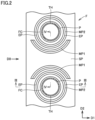
Fig. 2 is a cross-sectional view of a region A inFig. 1 taken along line II-II. -
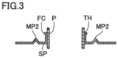
Fig. 3 is an end view taken along line III-III inFig. 2 . -
Fig. 4 is an end view taken along line IV-IV inFig. 2 . -
Fig. 5 is a refrigerant circuit diagram showing a refrigeration cycle apparatus according to the first embodiment. -
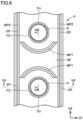
Fig. 6 is a cross-sectional view schematically showing a configuration of a portion of a heat exchanger according to a second embodiment corresponding toFig. 2 . -
Fig. 7 is an end view taken along line VII-VII inFig. 6 . -
Fig. 8 is an end view taken along line VIII-VIII inFig. 6 . -
Fig. 9 is a cross-sectional view schematically showing a configuration of a portion of a heat exchanger according to a third embodiment corresponding toFig. 2 . -
Fig. 10 is an end view taken along line X-X inFig. 9 . -
Fig. 11 is an end view taken along line XI-XI inFig. 9 . -
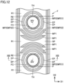
Fig. 12 is a cross-sectional view schematically showing a configuration of a portion of a heat exchanger according to a fourth embodiment corresponding toFig. 2 . -
Fig. 13 is an end view taken along line XIII-XIII inFig. 12 . -
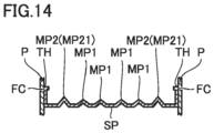
Fig. 14 is an end view taken along line XIV-XIV inFig. 12 . - Embodiments will be described hereinafter with reference to the drawings. In the following description, the same or corresponding portions are denoted by the same reference characters and description thereof will not be repeated.
- A configuration of a heat exchanger HE according to a first embodiment will be described with reference to
Figs. 1 to 4 . - Referring to
Figs. 1 and2 , heat exchanger HE includes a fin F and a heat transfer tube P. Fin F extends in a widthwise direction D1 along an air flow direction D0 and extends in a longitudinal direction D2 crossing air flow direction D0. Fin F is formed in a substantially rectangular shape. Heat transfer tube P passes through fin F. Heat transfer tube P is a circular pipe. Fin F has a through hole TH. Through hole TH is formed in a circular shape. Heat transfer tube P is inserted into through hole TH. - In the present embodiment, heat exchanger HE includes a plurality of fins F. The plurality of fins F are stacked on top of each other at intervals. Heat transfer tube P passes through the plurality of fins F in a direction D3 in which the plurality of fins F are stacked. Each of the plurality of fins F has a plurality of through holes TH. The plurality of through holes TH are aligned in longitudinal direction D2 of fin F. The plurality of through holes TH are spaced apart from each other in longitudinal direction D2 of fin F.
- Widthwise direction D1 of fin F is orthogonal to longitudinal direction D2. Widthwise direction D1 of fin F may be a horizontal direction. Longitudinal direction D2 of fin F may be an up-down direction (vertical direction). Direction D3 in which fins F are stacked is orthogonal to widthwise direction D1 and longitudinal direction D2 of fin F.
- Heat transfer tube P has a plurality of heat transfer portions P1 and a plurality of connection portions P2. Each of the plurality of heat transfer portions P1 passes through the plurality of fins F. Each of the plurality of heat transfer portions P1 is inserted into the plurality of through holes TH in direction D3 in which the plurality of fins F are stacked. The plurality of heat transfer portions P1 are formed linearly. Each of the plurality of heat transfer portions P1 extends in direction D3 in which the plurality of fins F are stacked.
- Each of the plurality of connection portions P2 is a portion that connects corresponding heat transfer portions P1 of the plurality of heat transfer portions P1 outside the plurality of fins F. Each of the plurality of connection portions P2 is formed in a U-shape. Each of the plurality of connection portions P2 connects heat transfer tubes P adjacent to each other in longitudinal direction D2 of fin F. Each of the plurality of connection portions P2 is connected to ends of heat transfer portions P1 in direction D3 in which fins F are stacked. The plurality of heat transfer portions P1 are located at a plurality of stages in longitudinal direction D2 of fin F. In the present embodiment, the plurality of heat transfer portions P1 are located at four stages along longitudinal direction D2 of fin F.
- The plurality of heat transfer portions P1 are connected by the plurality of connection portions P2 as follows. Heat transfer portion P1 in the first stage is connected to heat transfer portion P1 in the second stage by connection portion P2 on the back side in direction D3 in which the plurality of fins F are stacked. Heat transfer portion P1 in the second stage is connected to heat transfer portion P1 in the third stage by connection portion P2 on the front side in direction D3 in which the plurality of fins F are stacked. Heat transfer portion P1 in the third stage is connected to heat transfer portion P1 in the fourth stage by connection portion P2 on the back side in direction D3 in which the plurality of fins F are stacked. In this manner, heat transfer tube P is configured to meander in longitudinal direction D2 of fin F.
- A structure of fin F will be described in detail with reference to
Figs. 2 to 4 . - Fin F includes a planar portion SP, a first protruding portion MP1, a second protruding portion MP2, and a fin collar FC. Planar portion SP is formed in a planar shape. Planar portion SP is formed in a flat plate shape.
- First protruding portion MP1 and second protruding portion MP2 protrude from planar portion SP. In the present embodiment, first protruding portion MP1 and second protruding portion MP2 protrude from planar portion SP in the same direction. In the present embodiment, fin F includes a plurality of first protruding portions MP1 and a plurality of second protruding portions MP2.
- First protruding portion MP1 is curved along longitudinal direction D2 of fin F. First protruding portion MP1 is curved to protrude in longitudinal direction D2 of fin F. First protruding portion MP1 has a portion extending along longitudinal direction D2 of fin F. First protruding portion MP1 also has a portion extending along widthwise direction D1 of fin F. First protruding portion MP1 is located to be displaced from the center of through hole TH in widthwise direction D1 of fin F. In the present embodiment, first protruding portion MP1 is formed in a circular arc shape. In the present embodiment, first protruding portions MP1 have the same width.
- The plurality of first protruding portions MP1 are aligned in longitudinal direction D2 of fin F. First protruding portions MP1 are spaced apart from each other in longitudinal direction D2 of fin F. In the present embodiment, two first protruding portions MP1 are located between two through holes TH in longitudinal direction D2 of fin F. Two first protruding portions MP1 are located to face each other in longitudinal direction D2 of fin F. First protruding portions MP1 facing each other are curved to protrude toward each other.
- First protruding portions MP1 are formed in the same shape except for the direction in which first protruding portions MP1 are curved along longitudinal direction D2 of fin F. First protruding portions MP1 have the same radius of curvature. The respective centers of curvature of first protruding portions MP1 are linearly aligned with each other in longitudinal direction D2 of fin F. First protruding portions MP1 have the same width. First protruding portions MP1 have the same length.
- Each of the plurality of first protruding portions MP1 is longer than each of the plurality of second protruding portions MP2 in widthwise direction D1 of fin F. In longitudinal direction D2 of fin F, each of the plurality of first protruding portions MP1 is located between corresponding ones of the plurality of second protruding portions MP2. The respective centers of curvature of the plurality of first protruding portions MP1 are linearly aligned with the respective centers of the plurality of second protruding portions MP2 in longitudinal direction D2 of fin F.
- Second protruding portion MP2 has an extending portion EP extending in longitudinal direction D2 of fin F. Second protruding portion MP2 has a portion extending along longitudinal direction D2 of fin F. Extending portion EP is located to overlap the center of through hole TH in widthwise direction D1 of fin F.
- In the present embodiment, second protruding portion MP2 is located between first protruding portion MP1 and through hole TH. Second protruding portion MP2 surrounds through hole TH. Second protruding portion MP2 is formed in an annular shape. Second protruding portion MP2 protrudes from planar portion SP more than first protruding portion MP1.
- The plurality of second protruding portions MP2 are formed in the same shape. The respective centers of the plurality of second protruding portions MP2 are aligned linearly in longitudinal direction D2 of fin F. The plurality of second protruding portions MP2 have the same width. The plurality of second protruding portions MP2 have the same diameter.
- First protruding portion MP1 and second protruding portion MP2 protrude from planar portion SP less than fin collar FC.
- Fin collar FC is formed in a cylindrical shape. Heat transfer tube P is inserted into fin collar FC. The outer circumferential surface of heat transfer tube P fits onto the inner circumferential surface of fin collar FC. Fin collar FC protrudes from planar portion SP. In the present embodiment, fin collar FC protrudes from planar portion SP in the same direction as that of first protruding portion MP1 and second protruding portion MP2.
- Fin collar FC includes a circumferential wall and a flange. The circumferential wall protrudes from planar portion SP. The flange extends outward from the circumferential wall. The flange is provided at the edge of the circumferential wall opposite to planar portion SP. In the present embodiment, fin F includes a plurality of fin collars FC.
- A configuration of a
refrigeration cycle apparatus 100 including heat exchanger HE according to the first embodiment will be described with reference toFig. 5 .Refrigeration cycle apparatus 100 is, for example, an air conditioner or a refrigerator. The first embodiment will describe an air conditioner as an example ofrefrigeration cycle apparatus 100.Refrigeration cycle apparatus 100 includes a refrigerant circuit RC, refrigerant, a controller CD, andair blowers Refrigeration cycle apparatus 100 includes a refrigerant circulation device RCD. Refrigerant circulation device RCD is configured to circulate refrigerant for performing heat exchange with air in heat exchanger HE. The first embodiment will describerefrigeration cycle apparatus 100 including acompressor 1 incorporated as refrigerant circulation device RCD. Refrigerant circulation device RCD may be a refrigerant pump. - Refrigerant circuit RC includes
compressor 1, a four-way valve 2, anoutdoor heat exchanger 3, apressure reducing valve 4, and anindoor heat exchanger 5. Heat exchanger HE described above may be applied to at least one ofoutdoor heat exchanger 3 andindoor heat exchanger 5.Compressor 1, four-way valve 2,outdoor heat exchanger 3,pressure reducing valve 4, andindoor heat exchanger 5 are connected by a pipe. Refrigerant circuit RC is configured to circulate the refrigerant. Refrigerant circuit RC is configured to perform a refrigeration cycle in which the refrigerant circulates while changing its phase. -
Compressor 1, four-way valve 2,outdoor heat exchanger 3,pressure reducing valve 4, controller CD, andair blower 6 are housed in anoutdoor unit 101.Indoor heat exchanger 5 andair blower 7 are housed in anindoor unit 102. - Refrigerant circuit RC is configured such that the refrigerant circulates in order of
compressor 1, four-way valve 2, outdoor heat exchanger (condenser) 3,pressure reducing valve 4, indoor heat exchanger (evaporator) 5, and four-way valve 2 during a cooling operation. Refrigerant circuit RC is also configured such that the refrigerant circulates in order ofcompressor 1, four-way valve 2, indoor heat exchanger (condenser) 5,pressure reducing valve 4, outdoor heat exchanger (evaporator) 3, and four-way valve 2 during a heating operation. - The refrigerant flows through refrigerant circuit RC in order of
compressor 1, the condenser,pressure reducing valve 4, and the evaporator. - Controller CD is configured to control each device of
refrigeration cycle apparatus 100 by, for example, performing calculations or providing instructions. Controller CD is electrically connected tocompressor 1, four-way valve 2,pressure reducing valve 4,air blowers -
Compressor 1 is configured to compress the refrigerant for performing heat exchange with the air in heat exchanger HE.Compressor 1 is configured to compress the sucked refrigerant and discharge the compressed refrigerant.Compressor 1 may be configured to have a variable capacity.Compressor 1 may be configured to have a capacity changing through the adjustment of the rotation speed ofcompressor 1 based on an instruction from controller CD. - Four-
way valve 2 is configured to switch a refrigerant flow such that the refrigerant compressed bycompressor 1 flows tooutdoor heat exchanger 3 orindoor heat exchanger 5. Four-way valve 2 is configured such that the refrigerant discharged fromcompressor 1 flows to outdoor heat exchanger (condenser) 3 during the cooling operation. Four-way valve 2 is also configured such that the refrigerant discharged fromcompressor 1 flows to indoor heat exchanger (evaporator) 5 during the heating operation. -
Outdoor heat exchanger 3 is configured to exchange heat between the refrigerant flowing insideoutdoor heat exchanger 3 and the air flowing outsideoutdoor heat exchanger 3.Outdoor heat exchanger 3 is configured to function as the condenser that condenses the refrigerant during the cooling operation and function as the evaporator that evaporates the refrigerant during the heating operation. -
Pressure reducing valve 4 is configured to reduce pressure by expanding the refrigerant condensed by the condenser.Pressure reducing valve 4 is configured to reduce the pressure of the refrigerant condensed by outdoor heat exchanger (condenser) 3 during the cooling operation and reduce the pressure of the refrigerant condensed by indoor heat exchanger (evaporator) 5 during the heating operation.Pressure reducing valve 4 is, for example, a solenoid valve. -
Indoor heat exchanger 5 is configured to exchange heat between the refrigerant flowing insideindoor heat exchanger 5 and the air flowing outsideindoor heat exchanger 5.Indoor heat exchanger 5 is configured to function as the evaporator that evaporates the refrigerant during the cooling operation and function as the condenser that condenses the refrigerant during the heating operation. -
Air blower 6 is configured to blow outdoor air tooutdoor heat exchanger 3. In other words,air blower 6 is configured to supply air tooutdoor heat exchanger 3.Air blower 6 may be configured to adjust the amount of heat exchange between the refrigerant and the air by adjusting the rotation speed ofair blower 6 based on an instruction from controller CD, thereby adjusting an amount of heat exchange between the refrigerant and the air. -
Air blower 7 is configured to blow indoor air toindoor heat exchanger 5. In other words,air blower 7 is configured to supply air toindoor heat exchanger 5.Air blower 7 may be configured to adjust the amount of the air flowing aroundindoor heat exchanger 5 through the adjustment of the rotation speed ofair blower 7 based on an instruction from controller CD, thereby adjusting an amount of heat exchange between the refrigerant and the air. - Next, an operation of
refrigeration cycle apparatus 100 will be described with reference toFig. 5 . InFig. 5 , the solid arrows indicate a refrigerant flow during the cooling operation, and the dashed arrows indicate a refrigerant flow during the heating operation. -
Refrigeration cycle apparatus 100 can selectively perform the cooling operation and the heating operation. During the cooling operation, the refrigerant circulates through refrigerant circuit RC in order ofcompressor 1, four-way valve 2,outdoor heat exchanger 3,pressure reducing valve 4,indoor heat exchanger 5, and four-way valve 2. During the cooling operation,outdoor heat exchanger 3 functions as the condenser. Heat is exchanged between the refrigerant flowing throughoutdoor heat exchanger 3 and the air blown byair blower 6. During the cooling operation,indoor heat exchanger 5 functions as the evaporator. Heat is exchanged between the refrigerant flowing throughindoor heat exchanger 5 and the air blown byair blower 7. - During the heating operation, the refrigerant circulates through refrigerant circuit RC in order of
compressor 1, four-way valve 2,indoor heat exchanger 5,pressure reducing valve 4,outdoor heat exchanger 3, and four-way valve 2. During the heating operation,indoor heat exchanger 5 functions as the condenser. Heat is exchanged between the refrigerant flowing throughindoor heat exchanger 5 and the air blown byair blower 7. During the heating operation,outdoor heat exchanger 3 functions as the evaporator. Heat is exchanged between the refrigerant flowing throughoutdoor heat exchanger 3 and the air blown byair blower 6. - Next, functions and effects of the first embodiment will be described.
- In heat exchanger HE according to the first embodiment, first protruding portion MP1 and second protruding portion MP2 protrude from planar portion SP, and thus, an influence of a dead water region can be suppressed. This can improve a heat transfer coefficient of fin F. Also, the strength of fin F can be improved by first protruding portion MP1 and second protruding portion MP2.
- Extending portion EP of second protruding portion MP2 extending in longitudinal direction D2 is located to overlap the center of through hole TH in widthwise direction D1. This can further improve the strength of fin F.
- In heat exchanger HE according to the first embodiment, second protruding portion MP2 is located between first protruding portion MP1 and through hole TH and surrounds through hole TH. This can improve the strength of fin F so as to surround through hole TH by second protruding portion MP2.
- Heat exchanger HE and
refrigeration cycle apparatus 100 according to a second embodiment have the same configuration, functions and effects as those of heat exchanger HE andrefrigeration cycle apparatus 100 according to the first embodiment unless otherwise specified. - The structure of fin F of heat exchanger HE according to the second embodiment will be described with reference to
Figs. 6 to 8 . - Second protruding portion MP2 extends linearly in longitudinal direction D2 of fin F. Second protruding portion MP2 continuously extends from one end to the other end of fin F in longitudinal direction D2. Second protruding portion MP2 protrudes from planar portion SP opposite to first protruding portion MP1. Second protruding portion MP2 protrudes from planar portion SP opposite to fin collar FC.
- In the present embodiment, fin F includes a plurality of second protruding portions MP2. Second protruding portions MP2 extend parallel to each other in longitudinal direction D2 of fin F. Second protruding portions MP2 are located at the opposite ends of fin F in widthwise direction D1. Second protruding portions MP2 are located to sandwich first protruding portions MP1 and heat transfer tubes P. Second protruding portions MP2 have the same width.
- Next, functions and effects of the second embodiment will be described.
- In heat exchanger HE according to the second embodiment, second protruding portion MP2 extends linearly in longitudinal direction D2 of fin F. Thus, the strength of fin F can be improved in longitudinal direction D2 of fin F by second protruding portion MP2.
- In heat exchanger HE according to the second embodiment, second protruding portion MP2 protrudes from planar portion SP opposite to first protruding portion MP1. Thus, first protruding portion MP1 is not affected by the dead water region in the wake of second protruding portion MP2. This can improve the heat transfer coefficient of fin F.
- Heat exchanger HE and
refrigeration cycle apparatus 100 according to a third embodiment have the same configuration, functions and effects as those of heat exchanger HE andrefrigeration cycle apparatus 100 according to the first embodiment unless otherwise specified. - The structure of fin F of heat exchanger HE according to the third embodiment will be described with reference to
Figs. 9 to 11 . - Second protruding portions MP2 extend linearly in longitudinal direction D2 of fin F. Second protruding portions MP2 are spaced apart from each other in longitudinal direction D2 of fin F. Second protruding portions MP2 are separated from each other in longitudinal direction D2 of fin F. Second protruding portion MP2 protrudes from planar portion SP in the same direction as that of first protruding portion MP1. Second protruding portion MP2 protrudes from planar portion SP in the same direction as that of fin collar FC.
- Second protruding portion MP2 is located to be displaced from first protruding portion MP1 in widthwise direction D1 of fin F. Second protruding portion MP2 is located so as not to overlap first protruding portion MP1 in widthwise direction D1 of fin F.
- In the present embodiment, fin F includes a plurality of second protruding portions MP2. Second protruding portions MP2 extend parallel to each other in longitudinal direction D2 of fin F. Second protruding portions MP2 are located at the opposite ends of fin F in widthwise direction D1. Second protruding portions MP2 are located to sandwich first protruding portions MP1 and heat transfer tubes P. Second protruding portions MP2 have the same width.
- Next, functions and effects of the third embodiment will be described.
- In heat exchanger HE according to the third embodiment, second protruding portion MP2 is located to be displaced from first protruding portion MP1 in widthwise direction D1 of fin F. Thus, the strength of fin F can be improved as second protruding portion MP2 is located at a location on which a stress tends to concentrate, where no first protruding portion MP1 is formed.
- Also, first protruding portion MP1 is not affected by the dead water region in the wake of second protruding portion MP2. Thus, the heat transfer coefficient of fin F can be improved.
- Heat exchanger HE and
refrigeration cycle apparatus 100 according to a fourth embodiment have the same configuration, functions and effects as those of heat exchanger HE andrefrigeration cycle apparatus 100 according to the first embodiment unless otherwise specified. - The structure of fin F of heat exchanger HE according to the fourth embodiment will be described with reference to
Figs. 12 to 14 . - First protruding portions MP1 are aligned in longitudinal direction D2 of fin F. In the present embodiment, four first protruding portions MP1 are located between two through holes TH in longitudinal direction D2 of fin F.
- Two first protruding portions MP1 located above the lower through hole TH in longitudinal direction D2 of fin F are located adjacent to each other in longitudinal direction D2 of fin F. Two first protruding portions MP1 located below the upper through hole TH in longitudinal direction D2 of fin F are located adjacent to each other in longitudinal direction D2 of fin F.
- Two first protruding portions MP1 located adjacent to each other are curved to the same side along longitudinal direction D2. Also, two first protruding portions MP1 located to face each other in longitudinal direction D2 of fin F are curved to the opposite sides along longitudinal direction D2. Two first protruding portions MP1 located close to the upper through hole TH between two through holes TH are curved to project downward. Two first protruding portions MP1 located close to the lower through hole TH between two through holes TH are curved to protrude upward. The outer first protruding portion MP1 of the two first protruding portions MP1 curved to protrude downward is spaced apart from the outer first protruding portion MP1 of the two first protruding portions MP1 curved to protrude upward.
- The outer first protruding portions MP1 are formed in the same shape except for the direction in which the outer first protruding portions MP1 are curved along longitudinal direction D2 of fin F. The outer first protruding portions MP1 have the same radius of curvature. The respective centers of curvature of the outer first protruding portions MP1 are linearly aligned with each other in longitudinal direction D2 of fin F. The outer first protruding portions MP1 have the same width. The outer first protruding portions MP1 have the same length.
- The inner first protruding portions MP1 are formed in the same shape except for the direction in which the inner first protruding portions MP1 are curved along longitudinal direction D2 of fin F. The inner first protruding portions MP1 have the same radius of curvature. The respective centers of curvature of the inner first protruding portions MP1 are linearly aligned with each other in longitudinal direction D2 of fin F. The inner first protruding portions MP1 have the same width. The inner first protruding portions MP1 have the same length.
- In the present embodiment, the length of the outer first protruding portion MP1 in
widthwise direction D 1 of fin F is equal to the length of the inner first protruding portion MP1 in widthwise direction D1 of fin F. - First protruding portions MP1 are longer than second protruding portions MP2 in widthwise direction D1 of fin F. In longitudinal direction D2 of fin F, each of first protruding portions MP1 is located between second protruding portions MP2. The respective centers of curvature of first protruding portions MP1 are linearly aligned with the respective centers of curvature of second protruding portions MP2 in longitudinal direction D2 of fin F.
- The inner first protruding portion MP1 of two first protruding portions MP1 located above through hole TH in longitudinal direction D2 of fin F is adjacent to second protruding portion MP2. The inner first protruding portion MP1 of two first protruding portions MP1 located below through hole TH in longitudinal direction D2 of fin F is adjacent to second protruding portion MP2.
- Second protruding portion MP2 includes a first portion MP21 and a second portion MP22. First portion MP21 is located between first protruding portion MP1 and through hole TH. First portion MP21 surrounds through hole TH. First portion MP21 is formed in an annular shape. First portion MP21 protrudes from planar portion SP more than first protruding portion MP1. First portion MP21 protrudes from planar portion SP less than second portion MP22.
- Second portions MP22 extend linearly in longitudinal direction D2 of fin F. Second portion MP22 continuously extends from one end to the other end of fin F in longitudinal direction D2. Second portion MP22 protrudes from planar portion SP opposite to first portion MP21. Second portion MP22 extends from planar portion SP opposite to first protruding portion MP1 and fin collar FC.
- In the present embodiment, fin F includes a plurality of second portions MP22. Second portions MP22 extend parallel to each other in longitudinal direction D2 of fin F. Second portions MP22 are located at the opposite ends of fin F in widthwise direction D1. Second portions MP22 are located to sandwich first protruding portions MP1, first portions MP21, and heat transfer tubes P. Second portions MP22 have the same width.
- Fin F includes a first region R1 without through hole TH in widthwise direction D1 of fin F and a second region R2 with through hole TH in widthwise direction D1 of fin F. In first region R1, a first area of first protruding portions MP1 and second protruding portions MP2 extending in widthwise direction D1 of fin F is larger than a second area of first protruding portions MP1 and second protruding portions MP2 extending in longitudinal direction D2 of fin F. In second region R2, the first area is smaller than the second area.
- Next, functions and effects of the fourth embodiment will be described.
- In heat exchanger HE according to the fourth embodiment, the first area of first protruding portions MP1 and second protruding portions MP2 extending in widthwise direction D1 of fin F is larger than the second area of first protruding portions MP1 and second protruding portions MP2 extending in longitudinal direction D2 of fin F in first region R1, and the first area is smaller than the second area in second region R2. Thus, the strength of fin F can be improved in a location where the air flows less easily, while maximizing the improvement in heat transfer performance in a location where the air flows more easily.
- It should be understood that the embodiments disclosed herein are illustrative and non-restrictive in every respect. The scope of the present disclosure is defined by the scope of the claims, rather than the embodiments described above, and is intended to include any modifications within the scope and meaning equivalent to the scope of the claims.
- 1 compressor; 2 four-way valve; 3 outdoor heat exchanger; 4 pressure reducing valve; 5 indoor heat exchanger; 100 refrigeration cycle apparatus; D0 air flow direction; D1 widthwise direction; D2 longitudinal direction; EP extending portion; F fin; HE heat exchanger; MP1 first protruding portion; MP2 second protruding portion; MP21 first portion; MP22 second portion; P heat transfer tube; R1 first region; R2 second region; SP planar portion; TH through hole.
Claims (7)
- A heat exchanger comprising:a fin extending in a widthwise direction along an air flow direction and extending in a longitudinal direction crossing the air flow direction; anda heat transfer tube passing through the fin,the fin having a through hole,the heat transfer tube being inserted into the through hole,the fin comprisinga planar portion, anda first protruding portion and a second protruding portion protruding from the planar portion,the first protruding portion being curved along the longitudinal direction,the second protruding portion having an extending portion extending in the longitudinal direction,the extending portion being located to overlap a center of the through hole in the widthwise direction.
- The heat exchanger according to claim 1, wherein the second protruding portion is located between the first protruding portion and the through hole and surrounds the through hole.
- The heat exchanger according to claim 1, wherein the second protruding portion extends linearly in the longitudinal direction.
- The heat exchanger according to claim 3, wherein the second protruding portion protrudes from the planar portion opposite to the first protruding portion.
- The heat exchanger according to claim 3 or 4, wherein the second protruding portion is located to be displaced from the first protruding portion in the widthwise direction.
- The heat exchanger according to any one of claims 1 to 5, whereinthe fin comprisesa first region without the through hole in the widthwise direction, anda second region with the through hole in the widthwise direction,in the first region, a first area of the first protruding portion and the second protruding portion extending in the widthwise direction is larger than a second area of the first protruding portion and the second protruding portion extending in the longitudinal direction, andin the second region, the first area is smaller than the second area.
- A refrigeration cycle apparatus comprising:the heat exchanger according to any one of claims 1 to 6; anda refrigerant circulation device,the refrigerant circulation device being configured to circulate refrigerant for performing heat exchange with air in the heat exchanger.
Applications Claiming Priority (1)
| Application Number | Priority Date | Filing Date | Title |
|---|---|---|---|
| PCT/JP2020/044333 WO2022113298A1 (en) | 2020-11-27 | 2020-11-27 | Heat exchanger and refrigeration cycle device |
Publications (2)
| Publication Number | Publication Date |
|---|---|
| EP4253895A1 true EP4253895A1 (en) | 2023-10-04 |
| EP4253895A4 EP4253895A4 (en) | 2023-12-27 |
Family
ID=81755417
Family Applications (1)
| Application Number | Title | Priority Date | Filing Date |
|---|---|---|---|
| EP20963562.2A Withdrawn EP4253895A4 (en) | 2020-11-27 | 2020-11-27 | HEAT EXCHANGER AND REFRIGERANT CIRCUIT DEVICE |
Country Status (5)
| Country | Link |
|---|---|
| US (1) | US20230417495A1 (en) |
| EP (1) | EP4253895A4 (en) |
| JP (1) | JPWO2022113298A1 (en) |
| CN (1) | CN116438421A (en) |
| WO (1) | WO2022113298A1 (en) |
Family Cites Families (10)
| Publication number | Priority date | Publication date | Assignee | Title |
|---|---|---|---|---|
| JPS5730589U (en) * | 1980-07-25 | 1982-02-17 | ||
| JPS5730591U (en) * | 1980-07-25 | 1982-02-17 | ||
| JPS61235693A (en) * | 1985-04-10 | 1986-10-20 | Matsushita Electric Ind Co Ltd | Finned tube type heat exchanger |
| CA2180050A1 (en) * | 1996-04-04 | 1997-10-05 | Matthew K. Harris | Indented fins for an automotive heat exchanger |
| KR100518854B1 (en) | 2003-09-02 | 2005-09-30 | 엘지전자 주식회사 | Heat exchanger |
| JP2006138504A (en) * | 2004-11-10 | 2006-06-01 | Mitsubishi Heavy Ind Ltd | Heat exchanger and air conditioner |
| CN102305569A (en) * | 2011-08-16 | 2012-01-04 | 江苏萃隆精密铜管股份有限公司 | Heat exchanger tube used for evaporator |
| JP6337742B2 (en) * | 2014-11-04 | 2018-06-06 | パナソニックIpマネジメント株式会社 | Finned tube heat exchanger |
| JP2019163909A (en) * | 2018-03-20 | 2019-09-26 | 東京電力ホールディングス株式会社 | Fin tube type heat exchanger |
| CN110726325A (en) * | 2019-11-19 | 2020-01-24 | 广东美的暖通设备有限公司 | Fins for tube-fin heat exchangers, tube-fin heat exchangers and air conditioners |
-
2020
- 2020-11-27 EP EP20963562.2A patent/EP4253895A4/en not_active Withdrawn
- 2020-11-27 JP JP2022564961A patent/JPWO2022113298A1/ja active Pending
- 2020-11-27 CN CN202080107267.4A patent/CN116438421A/en active Pending
- 2020-11-27 WO PCT/JP2020/044333 patent/WO2022113298A1/en not_active Ceased
- 2020-11-27 US US18/247,096 patent/US20230417495A1/en not_active Abandoned
Also Published As
| Publication number | Publication date |
|---|---|
| JPWO2022113298A1 (en) | 2022-06-02 |
| CN116438421A (en) | 2023-07-14 |
| US20230417495A1 (en) | 2023-12-28 |
| WO2022113298A1 (en) | 2022-06-02 |
| EP4253895A4 (en) | 2023-12-27 |
Similar Documents
| Publication | Publication Date | Title |
|---|---|---|
| US10161656B2 (en) | Air conditioner having a bending tube which alters the flow of the refrigerant prior to entering the distributor | |
| JP6576577B1 (en) | Refrigerant distributor, heat exchanger, and air conditioner | |
| AU2018246166B2 (en) | Heat exchanger and refrigeration apparatus | |
| US20110120177A1 (en) | Heat exchanger for shedding water | |
| CN107076431A (en) | The indoor set of conditioner | |
| CN111902683B (en) | Heat Exchangers and Refrigeration Cycle Devices | |
| EP1628081B1 (en) | Indoor unit of air conditioner | |
| EP3825628B1 (en) | Refrigeration cycle device | |
| EP4253895A1 (en) | Heat exchanger and refrigeration cycle device | |
| EP4155645B1 (en) | Heat exchanger and air conditioner comprising said heat exchanger | |
| EP4253894A1 (en) | Heat exchanger and refrigeration cycle device | |
| JP7378502B2 (en) | air conditioner | |
| EP4253896A1 (en) | Heat exchanger and refrigeration cycle device | |
| CN111397195A (en) | Air conditioner | |
| EP4321820A1 (en) | Air conditioner | |
| US20230126980A1 (en) | Refrigeration Cycle Apparatus | |
| JPWO2020194442A1 (en) | Heat exchanger unit and refrigeration cycle equipment | |
| TWI810896B (en) | Dehumidifier | |
| JP7566155B2 (en) | Heat exchanger and air conditioning device | |
| KR100854324B1 (en) | Ceiling air conditioners | |
| EP4006474A1 (en) | Heat exchanger and refrigeration cycle device | |
| US20190360704A1 (en) | Outdoor unit for air-conditioning apparatus | |
| JP2019158286A (en) | Heat exchanger and air conditioner | |
| HK1151344A (en) | Heat exchanger for shedding water |
Legal Events
| Date | Code | Title | Description |
|---|---|---|---|
| STAA | Information on the status of an ep patent application or granted ep patent |
Free format text: STATUS: THE INTERNATIONAL PUBLICATION HAS BEEN MADE |
|
| PUAI | Public reference made under article 153(3) epc to a published international application that has entered the european phase |
Free format text: ORIGINAL CODE: 0009012 |
|
| STAA | Information on the status of an ep patent application or granted ep patent |
Free format text: STATUS: REQUEST FOR EXAMINATION WAS MADE |
|
| 17P | Request for examination filed |
Effective date: 20230518 |
|
| AK | Designated contracting states |
Kind code of ref document: A1 Designated state(s): AL AT BE BG CH CY CZ DE DK EE ES FI FR GB GR HR HU IE IS IT LI LT LU LV MC MK MT NL NO PL PT RO RS SE SI SK SM TR |
|
| A4 | Supplementary search report drawn up and despatched |
Effective date: 20231124 |
|
| RIC1 | Information provided on ipc code assigned before grant |
Ipc: F28F 17/00 20060101ALI20231120BHEP Ipc: F28D 1/047 20060101ALI20231120BHEP Ipc: F28F 19/00 20060101ALI20231120BHEP Ipc: F28F 1/32 20060101AFI20231120BHEP |
|
| DAV | Request for validation of the european patent (deleted) | ||
| DAX | Request for extension of the european patent (deleted) | ||
| STAA | Information on the status of an ep patent application or granted ep patent |
Free format text: STATUS: THE APPLICATION HAS BEEN WITHDRAWN |
|
| 18W | Application withdrawn |
Effective date: 20240829 |