EP4253882B1 - Frame for cold room doors - Google Patents
Frame for cold room doors Download PDFInfo
- Publication number
- EP4253882B1 EP4253882B1 EP23164325.5A EP23164325A EP4253882B1 EP 4253882 B1 EP4253882 B1 EP 4253882B1 EP 23164325 A EP23164325 A EP 23164325A EP 4253882 B1 EP4253882 B1 EP 4253882B1
- Authority
- EP
- European Patent Office
- Prior art keywords
- frame
- coupling
- heat sink
- seat
- recesses
- Prior art date
- Legal status (The legal status is an assumption and is not a legal conclusion. Google has not performed a legal analysis and makes no representation as to the accuracy of the status listed.)
- Active
Links
Images



Classifications
-
- F—MECHANICAL ENGINEERING; LIGHTING; HEATING; WEAPONS; BLASTING
- F25—REFRIGERATION OR COOLING; COMBINED HEATING AND REFRIGERATION SYSTEMS; HEAT PUMP SYSTEMS; MANUFACTURE OR STORAGE OF ICE; LIQUEFACTION SOLIDIFICATION OF GASES
- F25D—REFRIGERATORS; COLD ROOMS; ICE-BOXES; COOLING OR FREEZING APPARATUS NOT OTHERWISE PROVIDED FOR
- F25D23/00—General constructional features
- F25D23/02—Doors; Covers
- F25D23/028—Details
-
- F—MECHANICAL ENGINEERING; LIGHTING; HEATING; WEAPONS; BLASTING
- F25—REFRIGERATION OR COOLING; COMBINED HEATING AND REFRIGERATION SYSTEMS; HEAT PUMP SYSTEMS; MANUFACTURE OR STORAGE OF ICE; LIQUEFACTION SOLIDIFICATION OF GASES
- F25D—REFRIGERATORS; COLD ROOMS; ICE-BOXES; COOLING OR FREEZING APPARATUS NOT OTHERWISE PROVIDED FOR
- F25D21/00—Defrosting; Preventing frosting; Removing condensed or defrost water
- F25D21/04—Preventing the formation of frost or condensate
Definitions
- the present invention relates to a frame for cold room doors.
- the present invention relates to a frame for cold room doors provided with a heat sink.
- frames for cold room doors can comprise a peripheral box-like body adapted to be fixed to a wall of a cold room.
- the box-like body is provided, in a portion thereof close to the area of coupling to the respective door, with a heating element such as an electrical resistor, for example, adapted to distribute a certain amount of heat at the position of the frame where the gasket arranged on the door of the cold room is closed.
- a heating element such as an electrical resistor, for example, adapted to distribute a certain amount of heat at the position of the frame where the gasket arranged on the door of the cold room is closed.
- the box-like body includes a seat adapted to accommodate the electrical resistor and the related power supply cables, which is closed with a heat sink adapted to distribute heat.
- the heat sink is substantially a U-shaped element where, close to the end of each arm, there is arranged a protuberance towards the outside. Due to the elastic deformation possibility of the U-shaped arms, these can be inserted into the seat of the frame body, so that the protuberances can be coupled to respective side recesses of the seat obtained in the frame body.
- JP 2005 180883 A relates to a storage having a heater wire for preventing dew condensation on the packing that seals the inside of the storage.
- US 8 979 224 B2 relates to a mid-front plate installed on a middle wall of a refrigerator.
- a frame for cold room doors in which the position of the heat sink can follow the thermal expansions to which it is subjected when activated, without altering the consistency of the thermal contact between heating element and heat sink.
- the present invention relates to a frame for cold room doors, which is indicated by reference numeral 12 in the accompanying figures.
- the frame 12 comprises a box-like body 14 adapted to be fixed to a wall 16 of a cold room to obtain an at least partial framework.
- the frame 12 has a main extension in longitudinal direction. Therefore, elements to be defined based on an outline thereof according to a cross-section plane are obviously provided with a longitudinal extension as will be obvious per se to those skilled in the art.
- the body 14 is provided with a seat 18 adapted to contain heating means 20, and any power supply means 22 for the heating means 20, such as electric cables connected to a power supply, for example.
- the frame 12 comprises a heat sink 24 adapted to be coupled to the body 14 to close the seat 18, and to receive heat from the heating means 20.
- the heat sink 24 comprises an outer abutment surface 26 for a door of a cold room, and an inner surface 28 facing the heating means 20 in use.
- the heat sink 24 comprises coupling arms 30, 32 arranged to be cantilevered with respect to the inner surface 28, adapted to be contained at least partially between opposite side surfaces 34, 36 of the seat 18.
- the coupling arms 30, 32 are elastically deformable towards and away from each other.
- they are provided with at least one coupling tooth 38, 40.
- the opposite side surfaces 34, 36 of the seat 18 are provided with a plurality of mutually parallel recesses 42, 44, 46, 48, 50 adapted to house the at least one coupling tooth 38, 40.
- the coupling defined by the at least one coupling tooth 38, 40 arranged on each coupling arm 30, 32 with at least one of the recesses 42, 44, 46, 48, 50 on the respective opposite side surfaces 34, 36 thus defines a plurality of possible coupling positions between the heat sink element 24 and the seat 18.
- the coupling arms 30, 32 are each provided with two coupling teeth 38, 40.
- the opposite side surfaces 34, 36 can each be provided with at least three recesses 42, 44, 46, 48, 50, and preferably with at least five recesses 42, 44, 46, 48, 50.
- the recesses 42, 44, 46, 48, 50 can have a longitudinal extension substantially corresponding to the longitudinal extension of the seat 18.
- the at least one coupling tooth 38, 40 arranged on each coupling arm 30, 32 can also have a longitudinal extension substantially corresponding to the length of the heat sink 24.
- the seat 18 can have recesses 42, 44, 46, 48, 50 adapted to accommodate corresponding coupling teeth 38, 40 which can have, in turn, a longitudinal extension corresponding to the length of the heat sink 24, or have a smaller extension.
- the coupling teeth 38, 40 can have a limited longitudinal extension, e.g., of a few centimeters, and can be repeated at regular intervals, for example.
- the coupling teeth 38, 40 protrude from the respective coupling arm 30, 32 by an amount between 0.2 and 0.4 mm, preferably by about 0.3 mm. Moreover, the coupling teeth 38, 40 can have a substantially triangular shape according to a transverse plane. In particular, the distance between the coupling teeth 38, 40 can be between 0.4 and 0.6 mm, preferably of about 0.5 mm.
- the recesses 42, 44, 46, 48, 50 can have a depth between 0.3 and 0.6 mm, preferably of about 0.4 mm. Moreover, the recesses 42, 44, 46, 48, 50 can be mutually spaced apart by 0.4-0.6 mm, preferably by about 0.5 mm.
- the heat sink 24 is positioned above the seat 18 itself, so that the coupling arms 30, 32 face the seat 18.
- the heat sink 24 is then pushed so that the coupling arms 30, 32 enter into the seat 18 due to the fact that they are moved towards each other since they are elastically deformable.
- the at least one coupling tooth 38, 40 arranged on both coupling arms 30, 32 will engage at least one of the recesses 42, 44, 46, 48, 50 arranged on each of the opposite side surfaces 34, 36 of the seat 18, respectively.
- the heat sink through the coupling arms thereof will be positioned more or less deeply inside the seat 18 according to the actual contents, and according to the actual position, bending and twisting when mounting the seat 18 itself.
- the embodiment including two coupling teeth 38, 40 for each coupling arm 30, 32 and five recesses 42, 44, 46, 48, 50 parallel to one another on the opposite side surfaces 34, 36 of said seat 18, respectively, was found to be particularly advantageous.
- Such a structure allows four different relative positions between seat 18 and heat sink 24. Moreover, it allows achieving a perfect compromise between structure simplicity, modulability and solidity of the connection between body and heat sink.
- heat sink 24 and heating means 20 are free to slide in the longitudinal direction following the thermal expansions without introducing any strain and without altering the thermal contact between heat sink 24 and heating means 20.
- the body 14 can comprise three compartments 52, 54, 56 placed side-by-side, where the two side compartments 52, 56 have a greater height than the central compartment 54.
- the term "height” here means the dimension substantially perpendicular to the rear surface 74 of the body which, in use, is intended to rest on the wall of the cold room. Such a difference in height with respect to the two side compartments 52, 56 is adapted to obtain the seat 18 at the central compartment 54.
- the three compartments 52, 54, 56 can be substantially mutually aligned at the surface intended to be coupled to the wall of the cold room in use.
- a seat at the surface intended to be coupled to the wall of the cold room in use, a seat can be arranged for a gasket 76 adapted to prevent the body from sliding on the wall of the cold room, and to seal the air passages.
- the frame can also be provided with a fixing system 78 to the wall of the cold room. Since these means are known per se and not strictly inherent to the principles of the present invention, they will not be explored further.
- compartments 52, 54, 56 are essentially empty rectangles in cross-section, which share the walls placed side-by-side.
- the body 14 can be made of a polymer material, such as PVC.
- the heat sink 24 can be made of metal, preferably aluminum or an alloy thereof.
- the heat sink 24 can be made by extrusion.
- the heat sink 24 can comprise side wings 58, 60 which protrude laterally above the body 14 in use.
- the frame can comprise a resistor and cable-return-channel holder profile 62, adapted to be arranged inside the seat 18.
- the profile 62 can be a U-shaped element, for example, in which a seat is arranged at the bottom for a cable return channel, and in the upper part, a seat is arranged for the heating means 20, intended in use to face the heat sink 24.
- the frame can comprise a substantially C-shaped connection lining 64 of the rigid type, adapted to overlap a first front surface portion 66' which, in use, is close to the opening of the wall 16 on which the frame lies, a first side surface 68 adjacent to the front surface 66 of the body 14, and the edge 70 of the wall 16, by closing on a portion of the inner surface 168 of the panel 16, opposite to the first front surface portion 66'.
- the connection lining 64 can thus create a continuous lining surface for the body 14 and the wall 16.
- the transverse extension of the connection lining 64 and thus the thickness of the panel 16, which can be small in size, can be sized according to specific needs.
- the connection lining 64 can be adapted to contain a panel 16 with a thickness ranging between 60 mm and 240 mm.
- connection lining 64 overlaps the first front surface portion 66', and can be covered in turn by a side wing 58 of the heat sink 24.
- connection lining 64 can be a bent sheet made of metal, for example a painted sheet, or made of stainless steel.
- the frame 12 can comprise a side lining 72 adapted to partially overlap a second front surface portion 66", a second side surface 73 adjacent to the front surface 66 and opposite to the opening of the door, and a rear surface 74 of the body 14.
- connection lining 72 overlapping the second front surface portion 66" can be covered by a side wing 60 of the heat sink 24.
- the side lining 72 can be a bent sheet made of metal, preferably made of stainless steel.
- the modulability of the coupling between seat 18 and heat sink 24 can also be used when the side lining 72 and the connection lining 64 are provided.
- the heat sink can be coupled to the seat so that the side wings 58, 60 can be moved towards the respective side lining 72 and connection lining 64, so that they can be contained between the side wings and the frame body.
- the modulability of the coupling between seat 18 and heat sink 24 allows one of the two side and connection linings, or both, to be optionally inserted without modifying the heat sink itself, while however ensuring all the advantages already mentioned above with reference to the type of coupling achieved.
- the body 14 can be provided with an inner structural reinforcement 80, e.g., C-shaped, adapted to be coupled to respective inner walls of one of the compartments 52, 54, 56.
- the structural reinforcement can be placed at the compartment 56 which will be used to fix the frame to the wall of the cold room in use.
- the inner structural reinforcement can be made of metal, e.g., steel.
- the frame according to the present invention can be part of a kit comprising a door for cold rooms.
- a frame in which the particular coupling between heat sink and body allows easily obtaining a constant contact with the heating means.
- a frame which allows obtaining a modulable and simple coupling which can also be easily used by inexperienced people.
- the frame allows for the choice of whether to use a lining for the body or not, without any modifications to the frame components, due to the modulability of the coupling between the heat sink 24 and the seat 18.
- the body preferably made of PVC can be provided with an inner structural reinforcement 80.
- the inner structural reinforcement 80 can allow constructional elements such as hinges, screws, etc., for example, required for the construction of the door to be fastened.
- the coupling thus created between heat sink and heating means leaves the heat sink free to slide in the longitudinal direction following the thermal expansions without introducing any strain and without altering the thermal contact between heating element and heat sink.
- the frame according to the present invention allows particularly high health standards to be complied with, since no screws or equivalent elements are used to fix the heat sink to the body. Moreover, the coupling is free from sharp edges or areas where possible dirt can stagnate, and therefore it is a globally easily sanitizable structure.
Landscapes
- Engineering & Computer Science (AREA)
- Chemical & Material Sciences (AREA)
- Combustion & Propulsion (AREA)
- Physics & Mathematics (AREA)
- Mechanical Engineering (AREA)
- Thermal Sciences (AREA)
- General Engineering & Computer Science (AREA)
- Refrigerator Housings (AREA)
Description
- The present invention relates to a frame for cold room doors. In particular, the present invention relates to a frame for cold room doors provided with a heat sink.
- As is known, frames for cold room doors can comprise a peripheral box-like body adapted to be fixed to a wall of a cold room.
- The box-like body is provided, in a portion thereof close to the area of coupling to the respective door, with a heating element such as an electrical resistor, for example, adapted to distribute a certain amount of heat at the position of the frame where the gasket arranged on the door of the cold room is closed. This aims to prevent any condensate, due to the thermal gradient between the inside and outside of the cold room, from freezing and avoiding a correct coupling between frame and door.
- For this purpose, the box-like body includes a seat adapted to accommodate the electrical resistor and the related power supply cables, which is closed with a heat sink adapted to distribute heat.
- The coupling between heat sink and electrical resistor must necessarily be very precise, so that the heat sink is in contact with the electrical resistor. In fact, any lack of contact between electrical resistor and heat sink would result in a thermal gradient and thus a poor distribution of the heat energy with the possible formation of ice.
- Some technical solutions are known from the prior art, aimed to ensure contact between heat sink and electrical resistor.
- In fact, it is known to couple the heat sink to the frame body with screws, so that, due to the possibility to adjust the tightening, a precise coupling can be obtained, and the resistor sustained by its support can be placed in contact with the heat sink.
- However, this solution is clearly impractical and laborious, since each screw is to be tightened by the right amount so as to achieve the desired coupling between resistor and heat sink, but at the same time the tightening must not be such as to deform the heat sink along the longitudinal extension thereof.
- In order to avoid such drawbacks, it has been suggested to couple the body of the profile to the heat sink by snap-fit connection means. In this case, the heat sink is substantially a U-shaped element where, close to the end of each arm, there is arranged a protuberance towards the outside. Due to the elastic deformation possibility of the U-shaped arms, these can be inserted into the seat of the frame body, so that the protuberances can be coupled to respective side recesses of the seat obtained in the frame body.
- Although such a solution allows obtaining a simpler coupling as compared to the screw coupling, and allows the heating element to expand in length when switched on, it does not however allow an adjustable coupling between the frame body and the heat sink, adapted to maintain the contact between the electrical resistor and the heat sink itself under different conditions of use, such as different types of resistors, or different size variations of the frame body due to the use of linings for the body itself, for example.
- Therefore, although the prior art is widely used and appreciated, it is not free from drawbacks.
-
JP 2005 180883 A -
US 8 979 224 B2 relates to a mid-front plate installed on a middle wall of a refrigerator. - The need is thus felt to solve the drawbacks and limitations mentioned with reference to the prior art.
- Therefore, the need is felt to provide a frame for cold room doors which allows easily adjusting the position of the heat sink with respect to the resistor.
- Moreover, the need is felt to provide a frame for cold room doors, in which the position of the heat sink can be adjusted according to the actual thickness of the resistor used.
- Again, the need is felt for a frame for cold room doors of the modular type, which can also be used with additional components while allowing a secure coupling between the heat sink element and the resistor to be obtained.
- Moreover, the need is felt to provide a frame for cold room doors, in which the position of the heat sink can follow the thermal expansions to which it is subjected when activated, without altering the consistency of the thermal contact between heating element and heat sink. These needs are met by a frame for cold room doors according to claim 1, and a kit for cold rooms comprising a frame and a door according to claim 15.
- Further features and advantages of the present invention will become more comprehensible from the following description of preferred embodiments thereof, given by way of non-limiting examples, in which:
-
figure 1 diagrammatically shows a section view of a frame for a cold room door according to a possible embodiment of the present invention, mounted to a wall of a cold room; -
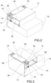
figures 2 and 3 diagrammatically show two perspective views according to different points of view of a frame portion for a cold room door according to a possible embodiment of the present invention; -
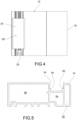
figure 4 diagrammatically shows a front view of the frame portion shown infigures 2 and 3 ; -
figure 5 diagrammatically shows a section view of a component of a frame for a cold room door according to a possible embodiment of the present invention; -
figure 6 diagrammatically shows a section view of two components of a frame for a cold room door according to a possible embodiment of the present invention, in disassembled conditions; -
figure 7 shows an enlarged detail of the respective coupling areas of the two components infigure 6 ; -
figure 8 diagrammatically shows a section view of the two components infigure 6 in an assembled condition; and -
figure 9 shows an enlarged detail of the coupling between the two components infigure 8 . - The elements or parts of elements common to the embodiments described below will be indicated by the same reference numerals.
- The present invention relates to a frame for cold room doors, which is indicated by
reference numeral 12 in the accompanying figures. - As can be seen in
figure 1 , theframe 12 comprises a box-like body 14 adapted to be fixed to awall 16 of a cold room to obtain an at least partial framework. - In this disclosure, reference will often be made to details of the frame which can be appreciated from a cross-section. However, as is very clear from
figures 2, 3 ,4 , theframe 12 has a main extension in longitudinal direction. Therefore, elements to be defined based on an outline thereof according to a cross-section plane are obviously provided with a longitudinal extension as will be obvious per se to those skilled in the art. - The
body 14 is provided with aseat 18 adapted to contain heating means 20, and any power supply means 22 for the heating means 20, such as electric cables connected to a power supply, for example. - Moreover, the
frame 12 comprises aheat sink 24 adapted to be coupled to thebody 14 to close theseat 18, and to receive heat from the heating means 20. In this regard, as can be seen for example infigure 8 , theheat sink 24 comprises anouter abutment surface 26 for a door of a cold room, and aninner surface 28 facing the heating means 20 in use. - The
heat sink 24 comprisescoupling arms inner surface 28, adapted to be contained at least partially betweenopposite side surfaces seat 18. Thecoupling arms coupling arms opposite side surfaces seat 18 in use, they are provided with at least onecoupling tooth - In this regard, the
opposite side surfaces seat 18 are provided with a plurality of mutuallyparallel recesses coupling tooth - The coupling defined by the at least one
coupling tooth coupling arm recesses opposite side surfaces heat sink element 24 and theseat 18. - According to a possible embodiment, the
coupling arms coupling teeth - In turn, the
opposite side surfaces recesses recesses - According to a possible embodiment, the
recesses seat 18. - Advantageously, the at least one
coupling tooth coupling arm heat sink 24. - In other words, the
seat 18 can haverecesses corresponding coupling teeth heat sink 24, or have a smaller extension. - According to a possible alternative embodiment (not shown in the accompanying figures), the
coupling teeth - The
coupling teeth respective coupling arm coupling teeth coupling teeth - According to a possible embodiment, the
recesses recesses - The operation of the coupling between
body 14 andheat sink 24 will now be described, with particular reference tofigures 6 and 7 , which show a disassembled condition of the two elements, andfigures 8 and 9 , which instead show an assembled condition. - According to the present invention, once the heating means 20 and any power supply means 22 have been positioned inside the
seat 18, theheat sink 24 is positioned above theseat 18 itself, so that thecoupling arms seat 18. Theheat sink 24 is then pushed so that thecoupling arms seat 18 due to the fact that they are moved towards each other since they are elastically deformable. Now, according to the actual thickness of the heating means 20 and any power supply means, according to a possible bending in the length direction caused by an imperfect assembly, or in light of the overall tolerances of the frame especially in the case of very large doors, the at least onecoupling tooth arms recesses seat 18, respectively. Since therecesses seat 18 are at different heights with respect to the bottom of theseat 18, the heat sink through the coupling arms thereof will be positioned more or less deeply inside theseat 18 according to the actual contents, and according to the actual position, bending and twisting when mounting theseat 18 itself. - In this regard, the embodiment including two coupling
teeth coupling arm recesses seat 18, respectively, was found to be particularly advantageous. Such a structure allows four different relative positions betweenseat 18 andheat sink 24. Moreover, it allows achieving a perfect compromise between structure simplicity, modulability and solidity of the connection between body and heat sink. - In any case, according to alternative embodiments, it is possible to provide a plurality of
coupling teeth recesses coupling teeth - Moreover, with the coupling thus created between
heat sink 24 and heating means 20, they are free to slide in the longitudinal direction following the thermal expansions without introducing any strain and without altering the thermal contact betweenheat sink 24 and heating means 20. - According to a possible embodiment, the
body 14, considering a cross-section thereof, can comprise threecompartments side compartments central compartment 54. The term "height" here means the dimension substantially perpendicular to therear surface 74 of the body which, in use, is intended to rest on the wall of the cold room. Such a difference in height with respect to the twoside compartments seat 18 at thecentral compartment 54. - Advantageously, the three
compartments - According to a possible embodiment, at the surface intended to be coupled to the wall of the cold room in use, a seat can be arranged for a
gasket 76 adapted to prevent the body from sliding on the wall of the cold room, and to seal the air passages. - The frame can also be provided with a fixing
system 78 to the wall of the cold room. Since these means are known per se and not strictly inherent to the principles of the present invention, they will not be explored further. - As can be seen in
figure 5 , for example, thecompartments - According to a possible embodiment, the
body 14 can be made of a polymer material, such as PVC. - The
heat sink 24 can be made of metal, preferably aluminum or an alloy thereof. Advantageously, theheat sink 24 can be made by extrusion. - According to a possible embodiment, the
heat sink 24 can compriseside wings body 14 in use. - As can be seen in
figures 1 ,2 and 3 , the frame can comprise a resistor and cable-return-channel holder profile 62, adapted to be arranged inside theseat 18. Theprofile 62 can be a U-shaped element, for example, in which a seat is arranged at the bottom for a cable return channel, and in the upper part, a seat is arranged for the heating means 20, intended in use to face theheat sink 24. - According to a possible embodiment, the frame can comprise a substantially C-shaped connection lining 64 of the rigid type, adapted to overlap a first front surface portion 66' which, in use, is close to the opening of the
wall 16 on which the frame lies, afirst side surface 68 adjacent to thefront surface 66 of thebody 14, and theedge 70 of thewall 16, by closing on a portion of theinner surface 168 of thepanel 16, opposite to the first front surface portion 66'. The connection lining 64 can thus create a continuous lining surface for thebody 14 and thewall 16. The transverse extension of the connection lining 64 and thus the thickness of thepanel 16, which can be small in size, can be sized according to specific needs. For example, the connection lining 64 can be adapted to contain apanel 16 with a thickness ranging between 60 mm and 240 mm. - As can be seen in
figure 1 , at least one portion of the connection lining 64 overlaps the first front surface portion 66', and can be covered in turn by aside wing 58 of theheat sink 24. - For example, the connection lining 64 can be a bent sheet made of metal, for example a painted sheet, or made of stainless steel.
- According to a possible embodiment, the
frame 12 can comprise a side lining 72 adapted to partially overlap a secondfront surface portion 66", asecond side surface 73 adjacent to thefront surface 66 and opposite to the opening of the door, and arear surface 74 of thebody 14. - As can be seen in
figure 1 , at least one portion of the connection lining 72 overlapping the secondfront surface portion 66" can be covered by aside wing 60 of theheat sink 24. - According to a possible embodiment, the side lining 72 can be a bent sheet made of metal, preferably made of stainless steel.
- Therefore, the modulability of the coupling between
seat 18 andheat sink 24 can also be used when the side lining 72 and the connection lining 64 are provided. In fact, when provided, the heat sink can be coupled to the seat so that theside wings - In other words, the modulability of the coupling between
seat 18 andheat sink 24 allows one of the two side and connection linings, or both, to be optionally inserted without modifying the heat sink itself, while however ensuring all the advantages already mentioned above with reference to the type of coupling achieved. - According to a possible embodiment, the
body 14 can be provided with an innerstructural reinforcement 80, e.g., C-shaped, adapted to be coupled to respective inner walls of one of thecompartments compartment 56 which will be used to fix the frame to the wall of the cold room in use. The inner structural reinforcement can be made of metal, e.g., steel. - Moreover, the frame according to the present invention can be part of a kit comprising a door for cold rooms.
- Now, the advantages which can be achieved by a frame according to the present invention are thus apparent.
- First, a frame is provided, in which the particular coupling between heat sink and body allows easily obtaining a constant contact with the heating means.
- Moreover, a frame is provided, which allows obtaining a modulable and simple coupling which can also be easily used by inexperienced people.
- Again, as previously mentioned, the frame allows for the choice of whether to use a lining for the body or not, without any modifications to the frame components, due to the modulability of the coupling between the
heat sink 24 and theseat 18. - Moreover, the body preferably made of PVC can be provided with an inner
structural reinforcement 80. Advantageously, the innerstructural reinforcement 80 can allow constructional elements such as hinges, screws, etc., for example, required for the construction of the door to be fastened. - Moreover, the coupling thus created between heat sink and heating means leaves the heat sink free to slide in the longitudinal direction following the thermal expansions without introducing any strain and without altering the thermal contact between heating element and heat sink.
- Again, the frame according to the present invention allows particularly high health standards to be complied with, since no screws or equivalent elements are used to fix the heat sink to the body. Moreover, the coupling is free from sharp edges or areas where possible dirt can stagnate, and therefore it is a globally easily sanitizable structure.
Claims (15)
- Frame (12) for cold room doors comprising a box-like body (14) adapted to be fixed to a wall (16) of a cold room to obtain an at least partial framework;said body (14) being provided with a seat (18) adapted to contain heating means (20), and any power supply means (22) for said heating means (20);said frame (12) comprising a heat sink (24) adapted to be coupled to said body (14) to close said seat (18), and to receive heat from said heating means (20); said heat sink (24) comprising an outer abutment surface (26) for a door of said cold room, and an inner surface (28) facing said heating means (20) in use;whereinsaid heat sink (24) comprises coupling arms (30, 32) arranged to be cantilevered with respect to said inner surface (28), adapted to be contained at least partially between opposite side surfaces (34, 36) of said seat (18), said coupling arms (30, 32) being elastically deformable towards and away from each other;said coupling arms (30, 32), on the surface thereof facing said opposite side surfaces (34, 36) of said seat (18) in use, being provided with at least one coupling tooth (38, 40), characterized in thatsaid opposite side surfaces (34, 36) of said seat (18) being provided with a plurality of mutually parallel recesses (42, 44, 46, 48, 50) at different heights with respect to the bottom of the seat (18) and adapted to house said at least one coupling tooth (38, 40);wherein the coupling defined by said at least one coupling tooth (38, 40) arranged on each coupling arm (30, 32) with at least one of said recesses (42, 44, 46, 48, 50) on said respective opposite side surfaces (34, 36) defines a plurality of possible coupling positions between said heat sink element (24) and said seat (18).
- Frame (12) according to claim 1, characterized in that said coupling arms (30, 32) are each provided with two coupling teeth (38, 40).
- Frame (12) according to any one of the preceding claims, characterized in that said opposite side surfaces (34, 36) are each provided with at least three recesses (42, 44, 46, 48, 50), preferably with five recesses (42, 44, 46, 48, 50).
- Frame (12) according to any one of the preceding claims, characterized in that said recesses (42, 44, 46, 48, 50) have a longitudinal extension substantially corresponding to the longitudinal extension of the seat (18) and/or said at least one coupling tooth (38, 40) arranged on each coupling arm (30, 32) has a longitudinal extension substantially corresponding to the length of said heat sink (24).
- Frame (12) according to any one of the preceding claims, characterized in that said at least one coupling tooth (38, 40) protrudes from said coupling arm (30, 32) by an amount between 0.2 and 0.4 mm, preferably by 0.3 mm; said coupling teeth being mutually spaced apart by 0.4 and 0.6 mm, preferably by about 0.5 mm.
- Frame (12) according to the preceding claim, characterized in that said at least one coupling tooth (38, 40) has a substantially triangular shape in a transverse plane.
- Frame (12) according to any one of the preceding claims, characterized in that said recesses (42, 44, 46, 48, 50) have a depth between 0.3 and 0.6 mm, preferably of about 0.4 mm; said recesses (42, 44, 46, 48, 50) being mutually spaced apart by 0.4-0.6 mm, preferably by about 0.5 mm.
- Frame (12) according to any one of the preceding claims, characterized in that said body (14) in cross section comprises three compartments (52, 54, 56) placed side-by-side, wherein the two side compartments (52, 56) have a greater height than the central compartment (54), so as to obtain said seat (18) at the central compartment (54), by virtue of the difference in height with respect to the two side compartments (52, 56), said frame preferably comprising an inner structural reinforcement (80), preferably C-shaped, adapted to be coupled to respective inner walls of one of the compartments (52, 54, 56).
- Frame (12) according to any one of the preceding claims, characterized in that said heat sink (24) comprises side wings (58, 60), which protrude laterally above said body (14) in use.
- Frame (12) according to any one of the preceding claims, characterized in that it comprises a resistor and cable-return-channel holder profile (62) adapted to be arranged inside said seat (18).
- Frame (12) according to any one of the preceding claims, characterized in that said body (14) is made of a polymer material, preferably PVC, and/or said heat sink is made of metal, preferably aluminum or an alloy thereof.
- Frame (12) according to any one of the preceding claims, characterized in that it comprises a substantially C-shaped connection lining (64) of the rigid type, adapted to overlap a first front surface portion (66') which, in use, is close to the opening of the wall (16) on which the frame lies, a first side surface (68) adjacent to the front surface (66) of the body (14), and the edge (70) of the wall (16), by closing on a portion of the inner surface (168) of the panel (16), opposite to the first front surface portion (66'); preferably at least one portion of said connection lining (64) overlapping said first front surface portion (66') is covered by a side wing (58) of said heat sink (24).
- Frame (12) according to any one of the preceding claims, characterized in that it comprises a side lining (72) adapted to partially overlap a second front surface portion (66"), a second side surface (73) adjacent to said front surface (66) and opposite to the opening of said door, and a rear surface (74) of said body (14); preferably, at least one portion of said side lining (72) overlapping said second front surface portion (66") is covered by a side wing (60) of said heat sink (24).
- Frame (12) according to the preceding claim, characterized in that said connection lining (64) is a bent sheet made of metal, preferably stainless steel, and said side lining (72) is a bent sheet made of metal, preferably stainless steel.
- Kit comprising a cold room door and a frame for cold rooms according to any one of the preceding claims.
Applications Claiming Priority (1)
| Application Number | Priority Date | Filing Date | Title |
|---|---|---|---|
| IT102022000006086A IT202200006086A1 (en) | 2022-03-29 | 2022-03-29 | FRAME FOR COLD STORAGE DOORS |
Publications (2)
| Publication Number | Publication Date |
|---|---|
| EP4253882A1 EP4253882A1 (en) | 2023-10-04 |
| EP4253882B1 true EP4253882B1 (en) | 2024-08-28 |
Family
ID=82019998
Family Applications (1)
| Application Number | Title | Priority Date | Filing Date |
|---|---|---|---|
| EP23164325.5A Active EP4253882B1 (en) | 2022-03-29 | 2023-03-27 | Frame for cold room doors |
Country Status (2)
| Country | Link |
|---|---|
| EP (1) | EP4253882B1 (en) |
| IT (1) | IT202200006086A1 (en) |
Family Cites Families (5)
| Publication number | Priority date | Publication date | Assignee | Title |
|---|---|---|---|---|
| JPS6122228Y2 (en) * | 1980-10-28 | 1986-07-03 | ||
| DE8815741U1 (en) * | 1988-12-19 | 1989-02-02 | Viessmann GmbH & Co, 8670 Hof | Door frame |
| JP2005180883A (en) * | 2003-12-24 | 2005-07-07 | Hoshizaki Electric Co Ltd | Storage chamber |
| KR20120136166A (en) * | 2011-06-08 | 2012-12-18 | 삼성전자주식회사 | Refrigerator |
| US11168934B2 (en) * | 2020-01-23 | 2021-11-09 | Bsh Home Appliances Corporation | Extruded plastic front frame profiles for cooling appliances |
-
2022
- 2022-03-29 IT IT102022000006086A patent/IT202200006086A1/en unknown
-
2023
- 2023-03-27 EP EP23164325.5A patent/EP4253882B1/en active Active
Also Published As
| Publication number | Publication date |
|---|---|
| EP4253882A1 (en) | 2023-10-04 |
| IT202200006086A1 (en) | 2023-09-29 |
Similar Documents
| Publication | Publication Date | Title |
|---|---|---|
| US11864670B2 (en) | Thermal frame | |
| US20100264782A1 (en) | Modular refrigeration and/or freezer appliance | |
| US6122869A (en) | Composite door and frame | |
| US8303059B2 (en) | Domestic appliance with concealed hinge | |
| US5687527A (en) | Suspended ceiling for cleanrooms | |
| CN103380340B (en) | Can be used for the housing of the device of domestic, catering trade or retail business | |
| US11684180B2 (en) | Mullion bracket | |
| CA2514829A1 (en) | Construction unit mounting system | |
| US3612821A (en) | Door frame construction | |
| JPS60212551A (en) | Double wall panel | |
| US8801116B1 (en) | Outside-mounted frame for refrigeration systems | |
| US9834941B1 (en) | Thermal break system for wall panels secured to an existing wall | |
| EP4253882A1 (en) | Frame for cold room doors | |
| CN221724688U (en) | Connecting devices and refrigeration equipment | |
| US4870769A (en) | Sign | |
| GB2454006A (en) | A support structure | |
| KR870000536Y1 (en) | Panel supporting device for a curtain wall | |
| US2701395A (en) | Refrigerator door | |
| GB2209063A (en) | Fastener for panels | |
| RU67141U1 (en) | SYSTEM OF FASTENING OF THE FACING PANELS OF THE CASSETTE TYPE | |
| JPS6246776Y2 (en) | ||
| KR100191351B1 (en) | Moon structure | |
| CN211647772U (en) | Assembled curtain wall window system and building curtain wall | |
| CN114151954A (en) | Air conditioner box body adopting broken cold bridge box plate structure | |
| CN119713711B (en) | Method for connecting the door panel of refrigeration equipment |
Legal Events
| Date | Code | Title | Description |
|---|---|---|---|
| PUAI | Public reference made under article 153(3) epc to a published international application that has entered the european phase |
Free format text: ORIGINAL CODE: 0009012 |
|
| STAA | Information on the status of an ep patent application or granted ep patent |
Free format text: STATUS: THE APPLICATION HAS BEEN PUBLISHED |
|
| AK | Designated contracting states |
Kind code of ref document: A1 Designated state(s): AL AT BE BG CH CY CZ DE DK EE ES FI FR GB GR HR HU IE IS IT LI LT LU LV MC ME MK MT NL NO PL PT RO RS SE SI SK SM TR |
|
| P01 | Opt-out of the competence of the unified patent court (upc) registered |
Effective date: 20231221 |
|
| STAA | Information on the status of an ep patent application or granted ep patent |
Free format text: STATUS: REQUEST FOR EXAMINATION WAS MADE |
|
| 17P | Request for examination filed |
Effective date: 20240131 |
|
| RBV | Designated contracting states (corrected) |
Designated state(s): AL AT BE BG CH CY CZ DE DK EE ES FI FR GB GR HR HU IE IS IT LI LT LU LV MC ME MK MT NL NO PL PT RO RS SE SI SK SM TR |
|
| GRAP | Despatch of communication of intention to grant a patent |
Free format text: ORIGINAL CODE: EPIDOSNIGR1 |
|
| STAA | Information on the status of an ep patent application or granted ep patent |
Free format text: STATUS: GRANT OF PATENT IS INTENDED |
|
| RIC1 | Information provided on ipc code assigned before grant |
Ipc: F25D 21/04 20060101ALI20240313BHEP Ipc: F25D 23/02 20060101AFI20240313BHEP |
|
| INTG | Intention to grant announced |
Effective date: 20240328 |
|
| RAP1 | Party data changed (applicant data changed or rights of an application transferred) |
Owner name: MISA S.R.L. |
|
| GRAS | Grant fee paid |
Free format text: ORIGINAL CODE: EPIDOSNIGR3 |
|
| GRAA | (expected) grant |
Free format text: ORIGINAL CODE: 0009210 |
|
| STAA | Information on the status of an ep patent application or granted ep patent |
Free format text: STATUS: THE PATENT HAS BEEN GRANTED |
|
| AK | Designated contracting states |
Kind code of ref document: B1 Designated state(s): AL AT BE BG CH CY CZ DE DK EE ES FI FR GB GR HR HU IE IS IT LI LT LU LV MC ME MK MT NL NO PL PT RO RS SE SI SK SM TR |
|
| REG | Reference to a national code |
Ref country code: CH Ref legal event code: EP |
|
| REG | Reference to a national code |
Ref country code: DE Ref legal event code: R096 Ref document number: 602023000450 Country of ref document: DE |
|
| REG | Reference to a national code |
Ref country code: IE Ref legal event code: FG4D |
|
| REG | Reference to a national code |
Ref country code: LT Ref legal event code: MG9D |
|
| PG25 | Lapsed in a contracting state [announced via postgrant information from national office to epo] |
Ref country code: NO Free format text: LAPSE BECAUSE OF FAILURE TO SUBMIT A TRANSLATION OF THE DESCRIPTION OR TO PAY THE FEE WITHIN THE PRESCRIBED TIME-LIMIT Effective date: 20241128 |
|
| REG | Reference to a national code |
Ref country code: AT Ref legal event code: MK05 Ref document number: 1718347 Country of ref document: AT Kind code of ref document: T Effective date: 20240828 |
|
| PG25 | Lapsed in a contracting state [announced via postgrant information from national office to epo] |
Ref country code: PL Free format text: LAPSE BECAUSE OF FAILURE TO SUBMIT A TRANSLATION OF THE DESCRIPTION OR TO PAY THE FEE WITHIN THE PRESCRIBED TIME-LIMIT Effective date: 20240828 Ref country code: NL Free format text: LAPSE BECAUSE OF FAILURE TO SUBMIT A TRANSLATION OF THE DESCRIPTION OR TO PAY THE FEE WITHIN THE PRESCRIBED TIME-LIMIT Effective date: 20240828 Ref country code: GR Free format text: LAPSE BECAUSE OF FAILURE TO SUBMIT A TRANSLATION OF THE DESCRIPTION OR TO PAY THE FEE WITHIN THE PRESCRIBED TIME-LIMIT Effective date: 20241129 Ref country code: FI Free format text: LAPSE BECAUSE OF FAILURE TO SUBMIT A TRANSLATION OF THE DESCRIPTION OR TO PAY THE FEE WITHIN THE PRESCRIBED TIME-LIMIT Effective date: 20240828 Ref country code: PT Free format text: LAPSE BECAUSE OF FAILURE TO SUBMIT A TRANSLATION OF THE DESCRIPTION OR TO PAY THE FEE WITHIN THE PRESCRIBED TIME-LIMIT Effective date: 20241230 |
|
| PG25 | Lapsed in a contracting state [announced via postgrant information from national office to epo] |
Ref country code: BG Free format text: LAPSE BECAUSE OF FAILURE TO SUBMIT A TRANSLATION OF THE DESCRIPTION OR TO PAY THE FEE WITHIN THE PRESCRIBED TIME-LIMIT Effective date: 20240828 |
|
| PG25 | Lapsed in a contracting state [announced via postgrant information from national office to epo] |
Ref country code: LV Free format text: LAPSE BECAUSE OF FAILURE TO SUBMIT A TRANSLATION OF THE DESCRIPTION OR TO PAY THE FEE WITHIN THE PRESCRIBED TIME-LIMIT Effective date: 20240828 |
|
| REG | Reference to a national code |
Ref country code: NL Ref legal event code: MP Effective date: 20240828 |
|
| PG25 | Lapsed in a contracting state [announced via postgrant information from national office to epo] |
Ref country code: AT Free format text: LAPSE BECAUSE OF FAILURE TO SUBMIT A TRANSLATION OF THE DESCRIPTION OR TO PAY THE FEE WITHIN THE PRESCRIBED TIME-LIMIT Effective date: 20240828 Ref country code: IS Free format text: LAPSE BECAUSE OF FAILURE TO SUBMIT A TRANSLATION OF THE DESCRIPTION OR TO PAY THE FEE WITHIN THE PRESCRIBED TIME-LIMIT Effective date: 20241228 |
|
| PG25 | Lapsed in a contracting state [announced via postgrant information from national office to epo] |
Ref country code: HR Free format text: LAPSE BECAUSE OF FAILURE TO SUBMIT A TRANSLATION OF THE DESCRIPTION OR TO PAY THE FEE WITHIN THE PRESCRIBED TIME-LIMIT Effective date: 20240828 |
|
| PG25 | Lapsed in a contracting state [announced via postgrant information from national office to epo] |
Ref country code: RS Free format text: LAPSE BECAUSE OF FAILURE TO SUBMIT A TRANSLATION OF THE DESCRIPTION OR TO PAY THE FEE WITHIN THE PRESCRIBED TIME-LIMIT Effective date: 20241128 Ref country code: ES Free format text: LAPSE BECAUSE OF FAILURE TO SUBMIT A TRANSLATION OF THE DESCRIPTION OR TO PAY THE FEE WITHIN THE PRESCRIBED TIME-LIMIT Effective date: 20240828 |
|
| PG25 | Lapsed in a contracting state [announced via postgrant information from national office to epo] |
Ref country code: RS Free format text: LAPSE BECAUSE OF FAILURE TO SUBMIT A TRANSLATION OF THE DESCRIPTION OR TO PAY THE FEE WITHIN THE PRESCRIBED TIME-LIMIT Effective date: 20241128 Ref country code: PT Free format text: LAPSE BECAUSE OF FAILURE TO SUBMIT A TRANSLATION OF THE DESCRIPTION OR TO PAY THE FEE WITHIN THE PRESCRIBED TIME-LIMIT Effective date: 20241230 Ref country code: PL Free format text: LAPSE BECAUSE OF FAILURE TO SUBMIT A TRANSLATION OF THE DESCRIPTION OR TO PAY THE FEE WITHIN THE PRESCRIBED TIME-LIMIT Effective date: 20240828 Ref country code: NO Free format text: LAPSE BECAUSE OF FAILURE TO SUBMIT A TRANSLATION OF THE DESCRIPTION OR TO PAY THE FEE WITHIN THE PRESCRIBED TIME-LIMIT Effective date: 20241128 Ref country code: NL Free format text: LAPSE BECAUSE OF FAILURE TO SUBMIT A TRANSLATION OF THE DESCRIPTION OR TO PAY THE FEE WITHIN THE PRESCRIBED TIME-LIMIT Effective date: 20240828 Ref country code: LV Free format text: LAPSE BECAUSE OF FAILURE TO SUBMIT A TRANSLATION OF THE DESCRIPTION OR TO PAY THE FEE WITHIN THE PRESCRIBED TIME-LIMIT Effective date: 20240828 Ref country code: IS Free format text: LAPSE BECAUSE OF FAILURE TO SUBMIT A TRANSLATION OF THE DESCRIPTION OR TO PAY THE FEE WITHIN THE PRESCRIBED TIME-LIMIT Effective date: 20241228 Ref country code: HR Free format text: LAPSE BECAUSE OF FAILURE TO SUBMIT A TRANSLATION OF THE DESCRIPTION OR TO PAY THE FEE WITHIN THE PRESCRIBED TIME-LIMIT Effective date: 20240828 Ref country code: GR Free format text: LAPSE BECAUSE OF FAILURE TO SUBMIT A TRANSLATION OF THE DESCRIPTION OR TO PAY THE FEE WITHIN THE PRESCRIBED TIME-LIMIT Effective date: 20241129 Ref country code: FI Free format text: LAPSE BECAUSE OF FAILURE TO SUBMIT A TRANSLATION OF THE DESCRIPTION OR TO PAY THE FEE WITHIN THE PRESCRIBED TIME-LIMIT Effective date: 20240828 Ref country code: ES Free format text: LAPSE BECAUSE OF FAILURE TO SUBMIT A TRANSLATION OF THE DESCRIPTION OR TO PAY THE FEE WITHIN THE PRESCRIBED TIME-LIMIT Effective date: 20240828 Ref country code: BG Free format text: LAPSE BECAUSE OF FAILURE TO SUBMIT A TRANSLATION OF THE DESCRIPTION OR TO PAY THE FEE WITHIN THE PRESCRIBED TIME-LIMIT Effective date: 20240828 Ref country code: AT Free format text: LAPSE BECAUSE OF FAILURE TO SUBMIT A TRANSLATION OF THE DESCRIPTION OR TO PAY THE FEE WITHIN THE PRESCRIBED TIME-LIMIT Effective date: 20240828 |
|
| PG25 | Lapsed in a contracting state [announced via postgrant information from national office to epo] |
Ref country code: SM Free format text: LAPSE BECAUSE OF FAILURE TO SUBMIT A TRANSLATION OF THE DESCRIPTION OR TO PAY THE FEE WITHIN THE PRESCRIBED TIME-LIMIT Effective date: 20240828 Ref country code: RO Free format text: LAPSE BECAUSE OF FAILURE TO SUBMIT A TRANSLATION OF THE DESCRIPTION OR TO PAY THE FEE WITHIN THE PRESCRIBED TIME-LIMIT Effective date: 20240828 Ref country code: DK Free format text: LAPSE BECAUSE OF FAILURE TO SUBMIT A TRANSLATION OF THE DESCRIPTION OR TO PAY THE FEE WITHIN THE PRESCRIBED TIME-LIMIT Effective date: 20240828 |
|
| PG25 | Lapsed in a contracting state [announced via postgrant information from national office to epo] |
Ref country code: EE Free format text: LAPSE BECAUSE OF FAILURE TO SUBMIT A TRANSLATION OF THE DESCRIPTION OR TO PAY THE FEE WITHIN THE PRESCRIBED TIME-LIMIT Effective date: 20240828 |
|
| PG25 | Lapsed in a contracting state [announced via postgrant information from national office to epo] |
Ref country code: CZ Free format text: LAPSE BECAUSE OF FAILURE TO SUBMIT A TRANSLATION OF THE DESCRIPTION OR TO PAY THE FEE WITHIN THE PRESCRIBED TIME-LIMIT Effective date: 20240828 |
|
| PG25 | Lapsed in a contracting state [announced via postgrant information from national office to epo] |
Ref country code: SK Free format text: LAPSE BECAUSE OF FAILURE TO SUBMIT A TRANSLATION OF THE DESCRIPTION OR TO PAY THE FEE WITHIN THE PRESCRIBED TIME-LIMIT Effective date: 20240828 Ref country code: IT Free format text: LAPSE BECAUSE OF FAILURE TO SUBMIT A TRANSLATION OF THE DESCRIPTION OR TO PAY THE FEE WITHIN THE PRESCRIBED TIME-LIMIT Effective date: 20240828 |
|
| REG | Reference to a national code |
Ref country code: DE Ref legal event code: R097 Ref document number: 602023000450 Country of ref document: DE |
|
| PLBE | No opposition filed within time limit |
Free format text: ORIGINAL CODE: 0009261 |
|
| STAA | Information on the status of an ep patent application or granted ep patent |
Free format text: STATUS: NO OPPOSITION FILED WITHIN TIME LIMIT |
|
| 26N | No opposition filed |
Effective date: 20250530 |
|
| PG25 | Lapsed in a contracting state [announced via postgrant information from national office to epo] |
Ref country code: SE Free format text: LAPSE BECAUSE OF FAILURE TO SUBMIT A TRANSLATION OF THE DESCRIPTION OR TO PAY THE FEE WITHIN THE PRESCRIBED TIME-LIMIT Effective date: 20240828 |
|
| REG | Reference to a national code |
Ref country code: DE Ref legal event code: R119 Ref document number: 602023000450 Country of ref document: DE |
|
| PG25 | Lapsed in a contracting state [announced via postgrant information from national office to epo] |
Ref country code: MC Free format text: LAPSE BECAUSE OF FAILURE TO SUBMIT A TRANSLATION OF THE DESCRIPTION OR TO PAY THE FEE WITHIN THE PRESCRIBED TIME-LIMIT Effective date: 20240828 |
|
| PG25 | Lapsed in a contracting state [announced via postgrant information from national office to epo] |
Ref country code: LU Free format text: LAPSE BECAUSE OF NON-PAYMENT OF DUE FEES Effective date: 20250327 |
|
| REG | Reference to a national code |
Ref country code: BE Ref legal event code: MM Effective date: 20250331 |
|
| PG25 | Lapsed in a contracting state [announced via postgrant information from national office to epo] |
Ref country code: DE Free format text: LAPSE BECAUSE OF NON-PAYMENT OF DUE FEES Effective date: 20251001 |
|
| PG25 | Lapsed in a contracting state [announced via postgrant information from national office to epo] |
Ref country code: FR Free format text: LAPSE BECAUSE OF NON-PAYMENT OF DUE FEES Effective date: 20250331 |
|
| PG25 | Lapsed in a contracting state [announced via postgrant information from national office to epo] |
Ref country code: BE Free format text: LAPSE BECAUSE OF NON-PAYMENT OF DUE FEES Effective date: 20250331 |
|
| PG25 | Lapsed in a contracting state [announced via postgrant information from national office to epo] |
Ref country code: IE Free format text: LAPSE BECAUSE OF NON-PAYMENT OF DUE FEES Effective date: 20250327 |