EP4253856A1 - Method of improving air cooled packaged units performance for multi-packaged-units installations - Google Patents
Method of improving air cooled packaged units performance for multi-packaged-units installations Download PDFInfo
- Publication number
- EP4253856A1 EP4253856A1 EP23165942.6A EP23165942A EP4253856A1 EP 4253856 A1 EP4253856 A1 EP 4253856A1 EP 23165942 A EP23165942 A EP 23165942A EP 4253856 A1 EP4253856 A1 EP 4253856A1
- Authority
- EP
- European Patent Office
- Prior art keywords
- array
- packaged
- units
- packaged units
- operating
- Prior art date
- Legal status (The legal status is an assumption and is not a legal conclusion. Google has not performed a legal analysis and makes no representation as to the accuracy of the status listed.)
- Pending
Links
- 238000000034 method Methods 0.000 title claims description 41
- 238000009434 installation Methods 0.000 title description 3
- 238000010438 heat treatment Methods 0.000 claims abstract description 33
- 238000004378 air conditioning Methods 0.000 claims abstract description 17
- 238000005057 refrigeration Methods 0.000 claims abstract description 15
- 238000009423 ventilation Methods 0.000 claims abstract description 10
- 239000012530 fluid Substances 0.000 claims description 117
- 230000001143 conditioned effect Effects 0.000 claims description 26
- 238000011144 upstream manufacturing Methods 0.000 claims description 16
- 230000003750 conditioning effect Effects 0.000 claims description 6
- 230000007423 decrease Effects 0.000 claims description 4
- 238000001816 cooling Methods 0.000 description 33
- 239000003507 refrigerant Substances 0.000 description 22
- XLYOFNOQVPJJNP-UHFFFAOYSA-N water Substances O XLYOFNOQVPJJNP-UHFFFAOYSA-N 0.000 description 11
- 238000004891 communication Methods 0.000 description 10
- 238000007906 compression Methods 0.000 description 7
- 238000005265 energy consumption Methods 0.000 description 7
- 239000013529 heat transfer fluid Substances 0.000 description 7
- 239000007788 liquid Substances 0.000 description 7
- 238000010586 diagram Methods 0.000 description 6
- 230000008569 process Effects 0.000 description 6
- 238000012546 transfer Methods 0.000 description 6
- 238000004088 simulation Methods 0.000 description 5
- 230000006870 function Effects 0.000 description 4
- 238000004458 analytical method Methods 0.000 description 3
- -1 but not limited to Substances 0.000 description 3
- 230000008859 change Effects 0.000 description 3
- 230000000875 corresponding effect Effects 0.000 description 3
- 238000007791 dehumidification Methods 0.000 description 3
- 230000007613 environmental effect Effects 0.000 description 3
- LYCAIKOWRPUZTN-UHFFFAOYSA-N Ethylene glycol Chemical compound OCCO LYCAIKOWRPUZTN-UHFFFAOYSA-N 0.000 description 2
- 230000003247 decreasing effect Effects 0.000 description 2
- 238000013461 design Methods 0.000 description 2
- 238000002474 experimental method Methods 0.000 description 2
- 230000001788 irregular Effects 0.000 description 2
- 238000004519 manufacturing process Methods 0.000 description 2
- 238000003491 array Methods 0.000 description 1
- 230000009286 beneficial effect Effects 0.000 description 1
- 230000008901 benefit Effects 0.000 description 1
- 238000007664 blowing Methods 0.000 description 1
- 230000006835 compression Effects 0.000 description 1
- 238000010276 construction Methods 0.000 description 1
- 239000004035 construction material Substances 0.000 description 1
- 230000002596 correlated effect Effects 0.000 description 1
- 230000000694 effects Effects 0.000 description 1
- 238000009408 flooring Methods 0.000 description 1
- WGCNASOHLSPBMP-UHFFFAOYSA-N hydroxyacetaldehyde Natural products OCC=O WGCNASOHLSPBMP-UHFFFAOYSA-N 0.000 description 1
- 230000007246 mechanism Effects 0.000 description 1
- 238000012545 processing Methods 0.000 description 1
- 230000004044 response Effects 0.000 description 1
- 238000010257 thawing Methods 0.000 description 1
Images




Classifications
-
- F—MECHANICAL ENGINEERING; LIGHTING; HEATING; WEAPONS; BLASTING
- F24—HEATING; RANGES; VENTILATING
- F24F—AIR-CONDITIONING; AIR-HUMIDIFICATION; VENTILATION; USE OF AIR CURRENTS FOR SCREENING
- F24F11/00—Control or safety arrangements
- F24F11/30—Control or safety arrangements for purposes related to the operation of the system, e.g. for safety or monitoring
-
- F—MECHANICAL ENGINEERING; LIGHTING; HEATING; WEAPONS; BLASTING
- F24—HEATING; RANGES; VENTILATING
- F24F—AIR-CONDITIONING; AIR-HUMIDIFICATION; VENTILATION; USE OF AIR CURRENTS FOR SCREENING
- F24F11/00—Control or safety arrangements
- F24F11/62—Control or safety arrangements characterised by the type of control or by internal processing, e.g. using fuzzy logic, adaptive control or estimation of values
- F24F11/63—Electronic processing
- F24F11/65—Electronic processing for selecting an operating mode
-
- F—MECHANICAL ENGINEERING; LIGHTING; HEATING; WEAPONS; BLASTING
- F24—HEATING; RANGES; VENTILATING
- F24F—AIR-CONDITIONING; AIR-HUMIDIFICATION; VENTILATION; USE OF AIR CURRENTS FOR SCREENING
- F24F11/00—Control or safety arrangements
- F24F11/30—Control or safety arrangements for purposes related to the operation of the system, e.g. for safety or monitoring
- F24F11/46—Improving electric energy efficiency or saving
-
- F—MECHANICAL ENGINEERING; LIGHTING; HEATING; WEAPONS; BLASTING
- F24—HEATING; RANGES; VENTILATING
- F24F—AIR-CONDITIONING; AIR-HUMIDIFICATION; VENTILATION; USE OF AIR CURRENTS FOR SCREENING
- F24F11/00—Control or safety arrangements
- F24F11/62—Control or safety arrangements characterised by the type of control or by internal processing, e.g. using fuzzy logic, adaptive control or estimation of values
- F24F11/63—Electronic processing
- F24F11/64—Electronic processing using pre-stored data
-
- F—MECHANICAL ENGINEERING; LIGHTING; HEATING; WEAPONS; BLASTING
- F24—HEATING; RANGES; VENTILATING
- F24F—AIR-CONDITIONING; AIR-HUMIDIFICATION; VENTILATION; USE OF AIR CURRENTS FOR SCREENING
- F24F11/00—Control or safety arrangements
- F24F11/70—Control systems characterised by their outputs; Constructional details thereof
- F24F11/72—Control systems characterised by their outputs; Constructional details thereof for controlling the supply of treated air, e.g. its pressure
- F24F11/74—Control systems characterised by their outputs; Constructional details thereof for controlling the supply of treated air, e.g. its pressure for controlling air flow rate or air velocity
- F24F11/77—Control systems characterised by their outputs; Constructional details thereof for controlling the supply of treated air, e.g. its pressure for controlling air flow rate or air velocity by controlling the speed of ventilators
-
- F—MECHANICAL ENGINEERING; LIGHTING; HEATING; WEAPONS; BLASTING
- F24—HEATING; RANGES; VENTILATING
- F24F—AIR-CONDITIONING; AIR-HUMIDIFICATION; VENTILATION; USE OF AIR CURRENTS FOR SCREENING
- F24F5/00—Air-conditioning systems or apparatus not covered by F24F1/00 or F24F3/00, e.g. using solar heat or combined with household units such as an oven or water heater
- F24F5/0007—Air-conditioning systems or apparatus not covered by F24F1/00 or F24F3/00, e.g. using solar heat or combined with household units such as an oven or water heater cooling apparatus specially adapted for use in air-conditioning
- F24F5/001—Compression cycle type
-
- F—MECHANICAL ENGINEERING; LIGHTING; HEATING; WEAPONS; BLASTING
- F24—HEATING; RANGES; VENTILATING
- F24F—AIR-CONDITIONING; AIR-HUMIDIFICATION; VENTILATION; USE OF AIR CURRENTS FOR SCREENING
- F24F2110/00—Control inputs relating to air properties
- F24F2110/10—Temperature
- F24F2110/12—Temperature of the outside air
-
- F—MECHANICAL ENGINEERING; LIGHTING; HEATING; WEAPONS; BLASTING
- F24—HEATING; RANGES; VENTILATING
- F24F—AIR-CONDITIONING; AIR-HUMIDIFICATION; VENTILATION; USE OF AIR CURRENTS FOR SCREENING
- F24F2110/00—Control inputs relating to air properties
- F24F2110/30—Velocity
- F24F2110/32—Velocity of the outside air
Definitions
- HVAC heating, ventilation, air conditioning, and refrigeration
- a heating, ventilation, air conditioning, and refrigeration (HVACR) system may include a group of rooftop units installed on the rooftop of a building.
- the rooftop units can include one or more heat exchangers to facilitate thermal energy exchange between a heat transfer fluid and the outdoor air.
- the heat transfer fluid can be part of a fluid circuit to condition indoor air.
- a fan can move the conditioned indoor air in an air distribution system to condition the entire building.
- the group of rooftop units can change the temperature profile of the outdoor air over the group. For example, in a cooling operating where the rooftop units release heat into outdoor air, the upstream rooftop units in the group can exhaust heat into the outdoor air, heating up the intake temperature of a downstream rooftop unit in the same group and decreasing the efficiency of the downstream rooftop unit.
- HVAC heating, ventilation, air conditioning, and refrigeration
- packaged units e.g., air cooled chillers, direct free cooling chillers, air handling units, air conditioning outdoor units, heat pumps, air-cooled condensers or condenser coils, or the like
- the disclosure relates to controls and methods for adjusting the operation of one or more packaged units of the array of the packaged units to improve performance and efficiency and to reduce energy consumption of the array in conditioning the space.
- the array of packaged units exchanges thermal energy with an ambient fluid in the environment.
- the array of packaged units can exhaust heat to the ambient fluid, such as air flowed by the wind in the environment.
- Upstream units can be some packaged units of the array disposed upstream from some other packaged units of the array relative to a flow direction of the ambient fluid (e.g., wind direction).
- Downstream units can be some packaged units of the array disposed downstream from some other packaged units of the array relative to the flow direction of the ambient fluid.
- the ambient fluid flows through the upstream units and can remove heat from the upstream units.
- the heat can increase the temperature of the ambient fluid exhausted from the upstream units, heating the ambient fluid flows to some of the downstream units.
- packaged units can operate most efficiently when receiving ambient fluid at a temperature within a desired temperature range.
- the downstream units receive ambient fluid above this temperature range (e.g., heated by the upstream units)
- the downstream units are susceptible to operating less efficiently, consuming more energy, and lowering the overall efficiency of the array.
- the operation e.g., turning off, shutting down, or the like
- the overall efficiency of the array can be improved.
- adjusting the operation of the packaged units can include increasing the operating load, decreasing the operating load, turning on, turning off, turning partially off, or the like.
- an array of packaged units providing heating, cooling, dehumidification, or the like, or a combination thereof, can benefit from adjusting the operation of one or more packaged units within the array to regulate the ambient fluid received by the downstream units.
- the array of packaged units can absorb heat from the ambient fluid. Upstream units absorbing heat can cool the ambient fluid received by downstream units to a temperature lower than the temperature range efficient for the packaged units. Accordingly, by adjusting or turning off some packaged units such that the temperature of the ambient fluid received by the downstream units is increased into the temperature range, the overall efficiency of the array can be improved.
- a heating, ventilation, air conditioning, and refrigeration (HVACR) system includes an array of packaged units; and a controller configured to obtain an operating condition of the array of packaged units, derive the operating condition to construct an operating pattern, select one or more packaged units to be adjusted to increase efficiency of the array of packaged units based on the operating pattern, and to adjust operation of the one or more packaged units selected by the controller.
- HVAC heating, ventilation, air conditioning, and refrigeration
- a method of operating a HVACR system includes obtaining an operating condition of an array of packaged units; deriving the operating condition to construct an operating pattern; selecting one or more packaged units in the array of packaged units to be adjusted to increase efficiency based on the operating pattern; and adjusting operation of the one or more packaged units selected by the controller.
- hot (or cold) air exhaust from operating packaged units can recirculate and result in higher (or lower) than ambient temperatures at coil entering air surfaces, causing a decrease in capacity and efficiency, which may result in packaged units going off line due to high (or low) entering air temperatures.
- Such issues can correlate with the number of packaged units, packaged unit layout, customer features such as walls or separators, generators, prevailing (or actual) wind speed/velocity and/or direction, or the like.
- Embodiments disclosed herein can provide tuning of the packaged units staging (e.g., turning on or off selected packaged units) based on the above factors to optimize overall site packaged units performance. In particular, the tuning is beneficial if there is packaged units redundancy and/or the site load is not at maximum.
- FIG. 1 is a schematic diagram of a refrigerant circuit 100, according to an embodiment.
- the refrigerant circuit 100 can include a compressor 120, a condenser 140, an expander 160, and an evaporator 180.
- the refrigerant circuit 100 may also include a controller (e.g., the controller 220 of FIG. 2 ) configured to control the operations of the compressor 120, the condenser 140, the expander 160, and/or the evaporator 180.
- a controller e.g., the controller 220 of FIG. 2
- the refrigerant circuit 100 can generally be applied in a variety of systems used to control an environmental condition (e.g., temperature, humidity, air quality, or the like) in a conditioned space.
- the conditioned space can be a space within an office building, a commercial building, a factory, a laboratory, a data center, a residential building, or the like.
- the refrigerant circuit 100 can be configured to be a cooling system (e.g., an air conditioning system) capable of operating in a cooling mode.
- the refrigerant circuit 100 can be configured to be a heat pump that can operate in a heating/defrost mode. It is appreciated that the refrigerant circuit 100 can configured to operate in a cooling mode and a heating/defrosting mode,
- the compressor 120, the condenser 140, the expander 160, and the evaporator 180 can be fluidly connected.
- An "expander” as described herein may also be referred to as an expansion device.
- the expander 160 can be an expansion valve, expansion plate, expansion vessel, orifice, or the like, or other such types of expansion mechanisms. It should be appreciated that the expander 160 may be any suitable type of expander used in the field for expanding a working fluid to cause the working fluid to decrease in pressure and temperature.
- the refrigerant circuit 100 is an example and can be configured to include more or less components.
- the refrigerant circuit 100 can include other components such as, but not limited to, an economizer heat exchanger, one or more flow control devices (e.g., a valve, a pump, etc.), a receiver tank, a dryer, a suction-liquid heat exchanger, or the like.
- the refrigerant circuit 100 can operate according to generally known principles.
- the refrigerant circuit 100 can be configured to heat and/or cool a liquid process fluid.
- the liquid process fluid can be a heat transfer fluid or medium (e.g., a liquid such as, but not limited to, water or the like).
- the refrigerant circuit 100 may be generally representative of a liquid chiller system.
- the refrigerant circuit 100 can alternatively be configured to heat and/or cool a gaseous process fluid (e.g., a heat transfer medium or fluid (e.g., a gas such as, but not limited to, air or the like), in which case the refrigerant circuit 100 may be generally representative of an air conditioner and/or heat pump.
- a gaseous process fluid e.g., a heat transfer medium or fluid (e.g., a gas such as, but not limited to, air or the like
- the refrigerant circuit 100 can operate as a vapor-compression circuit such that the compressor 120 compresses a working fluid (e.g., a heat transfer fluid such as, but not limited to, refrigerant or the like) from a relatively lower pressure gas to a relatively higher-pressure gas.
- a working fluid e.g., a heat transfer fluid such as, but not limited to, refrigerant or the like
- the relatively higher-pressure gas is at a relatively higher temperature, being discharged from the compressor 120 and flowing through the condenser 140.
- the working fluid flows through the condenser 140 and rejects heat to the process fluid (e.g., water, air, etc.), thereby cooling the working fluid.
- the cooled working fluid which is now in a liquid form, flows to the expander 160 that can reduce the pressure of the working fluid.
- the working fluid which is now in a mixed liquid and gaseous form flows to the evaporator 180.
- the working fluid flows through the evaporator 180 and absorbs heat from the process fluid (e.g., a heat transfer medium such as, but not limited to, water, a solution, air, etc.), heating the working fluid, and converting it to a gaseous form.
- the gaseous working fluid then returns to the compressor 120.
- the above-described process continues while the heat transfer circuit is operating, for example, in a cooling mode (e.g., while the compressor 120 is enabled).
- the refrigerant circuit 100 can be configured to operate as a free cooling/heating circuit to control one or more environmental conditions of the conditioned space.
- a free cooling/heating circuit can include a first heat exchanger and a second heat exchanger fluidly connected by a working fluid.
- the first and second heat exchangers of the free cooling/heating circuit can be dedicated heat exchangers in addition to the refrigeration circuit 100 having the compressor 120, the condenser 140, the expander 160, and the evaporator 180.
- the first and second heat exchangers can share, for example, the condenser 140 and the evaporator 180 such that the refrigeration circuit 100 can operate as a free cooling/heating circuit or a vapor compression circuit.
- the first heat exchanger can exchange thermal energy between a working fluid and an ambient fluid (e.g., outdoor air).
- the first exchanger can be disposed in a location suitable to exchange thermal energy with the ambient fluid.
- the location can include a rooftop of the conditioned space.
- the second heat exchanger can be the evaporator 180 to exchange thermal energy between the working fluid and fluid in the conditioned space.
- Fluid in the conditioned space can, for example, be indoor air.
- the first heat exchanger can be the condenser 140.
- the first heat exchanger can release thermal energy to the ambient fluid and cool the working fluid.
- a pump can move the cooled working fluid to the second heat exchanger to exchange thermal energy with the fluid in the conditioned space, heating the working fluid to be cooled by the ambient fluid again.
- the ambient fluid in a cooling operation, can have a temperature lower than the temperature of the fluid in the conditioned space.
- the pump can circulate the working fluid between the first and the second heat exchangers to move thermal energy from the ambient fluid to the fluid in the conditioned space.
- the ambient fluid in a heating operation, can have a temperature higher than the temperature of the fluid in the conditioned space.
- the working fluid can be any heat transfer fluid such as a refrigerant, water, a water solution, glycol fluid, or the like.
- FIG. 2 is a schematic view of a packaged unit 200, according to an embodiment.
- the packaged unit 200 can be any piece of HVACR equipment that exchanges thermal energy with the environment, for example, by absorbing or releasing thermal energy with an ambient fluid (e.g., outdoor air).
- the packaged unit 200 can include at least a portion of a fluid circuit to transfer thermal energy from the packaged unit 200 to the conditioned space.
- the fluid circuit can be a heat transfer circuit (such as, for example, as shown in FIG. 1 ) that is configured to be a free cooling/heating circuit, a vapor-compression circuit, or the like, or a combination thereof.
- an air cooled chiller can be an air cooled chiller, a free cooling chiller (e.g., a direct free cooling chiller), an air handling unit, an air conditioning outdoor unit, a heat pump, an air-cooled condenser or condenser coil, or the like.
- a free cooling chiller e.g., a direct free cooling chiller
- an air handling unit e.g., an air handling unit
- an air conditioning outdoor unit e.g., a heat pump
- a heat pump e.g., a heat pump, or the like.
- the air cooled chiller can include at least one heat exchanger disposed therein.
- the heat exchanger facilitates heat exchanging between air and a fluid circuit.
- the circuit can be a free heating/cooling circuit or a vapor-compression circuit to provide environmental control to a controlled space.
- the air cooled chiller can include a free cooling circuit configured to cool the condenser in a vapor-compression circuit.
- the free cooling circuit can include a liquid-air heat exchanger to cool the condenser.
- the air handling unit can include a fan or blower to move conditioned air through an air distribution system to condition the conditioned space.
- the air handling unit can include an air outlet that can release air into the environment.
- the air outlet can be an outlet of a heat exchanger configured to condense a working fluid, releasing an exhaust that is heated above the ambient temperature.
- the air conditioning outdoor unit can include a condenser configured to condense a refrigerant in a fluid circuit.
- a fan of the air conditioning outdoor unit can force the ambient fluid, such as outdoor air, through the condenser to remove thermal energy from the condenser.
- the air conditioning outdoor unit can be fluidly connected with an evaporator, an expander, and a compressor to form the fluid circuit.
- the fluid circuit can include a vapor-compression circuit. It is appreciated that the evaporator, the expander, and/or the compressor may or may not be contained within the same housing of the air conditioning outdoor unit.
- the heat pump can include an evaporator configured to evaporate a refrigerant fluidly connecting a condenser, a compressor, and an expander with the evaporator in a refrigeration circuit.
- the heat pump can include an evaporator configured to evaporate a refrigerant in a fluid circuit.
- a fan of the heat pump can force the ambient fluid, such as outdoor air, through the evaporator to provide thermal energy to evaporate the refrigerant.
- the heat pump can be fluidly connected with a condenser, an expander, and a compressor to form the fluid circuit.
- the fluid circuit can include a vapor-compression circuit. It is appreciated that the condenser, the expander, and/or the compressor may or may not be contained within the same housing of the heat pump.
- the packaged unit 200 can include a housing (or enclosure) 201 configured to contain one or more HVACR system equipment, such as the compressor 120, the condenser 140, the expander 160, and the evaporator 180 of the refrigeration circuit 100 of FIG. 1 .
- a housing (or enclosure) 201 configured to contain one or more HVACR system equipment, such as the compressor 120, the condenser 140, the expander 160, and the evaporator 180 of the refrigeration circuit 100 of FIG. 1 .
- the housing 201 of the packaged unit 200 can contain a compressor 210, an evaporator 230, a condenser 240, a controller 220, and one or more panels 270.
- the condenser 240 is connected to an air coil 250 and one or more fans 280.
- the compressor 210 can be a fixed speed or variable speed compressor to compress a working fluid.
- the fans 280 can be single speed or variable speed and/or fans with a multiple number of fan stages or discrete steps to move air, for example, through the air coil 250.
- the panels 270 can be configured to be removable to provide access to the housing 201.
- the condenser 240 and its air coil 250 in the embodiment shown are one example of an air cooled condenser, however, it will be appreciated that the specific condenser 240/coil 250 combination shown is merely exemplary.
- the packaged unit 200 can be considered as a single unit within the HVAC system and be supported by a frame 260. It will be appreciated that the specific configuration shown in FIG. 2 is merely exemplary, as other packaged designs, layouts, and specific configurations may be employed.
- controller 220 can include a processor (not shown), a memory (not shown), and optionally a clock (not shown) and an input/output (I/O) interface (not shown).
- the controller 220 can be configured to receive data as input from various components within the HVACR system, such as the components shown in FIG. 1 and FIG. 2 , and can also send command or control signals as output to various components within of the HVACR system.
- controller 220 can be a central controller in communication with one or more of the packaged units 200 in the array 300, and can be configured to control the operation of one or more of the packaged units 200.
- the controller 220 can be configured to communicate with or control the packaged units 200 or other components in the system utilizing any suitable communications including power line communications, Pulse Width Modulation (PWM) communications, Local Interconnect Network (LIN) communications, Controller Area Network (CAN) communications, or the like.
- PWM Pulse Width Modulation
- LIN Local Interconnect Network
- CAN Controller Area Network
- the communications can include wired and/or wireless, analog and/or digital communications.
- the communication can include communications over telematics.
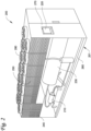
- FIG. 3A is a perspective view of an array 300 of packaged units 200, according to an embodiment.
- the array 300 can include one or more packaged units 200 arranged in a pattern. As illustrated, the array 300 can include twenty packaged units 200 arranged in a pattern of a 4 by 5 rectangular grid. It is appreciated that the packaged units 200 can be arranged in any suitable pattern as, for example, but not limited to, a grid, a circle, irregular, or a combination thereof. It is appreciated that the size of the array 300 can include any number of the same or different packaged units 200. For example, all the packaged units 200 of the array 300 can each have a full operating load of a first heating or cooling capacity. A full operating load can be the maximum output of the packaged unit 200 as designed by the manufacture of the packaged unit 200.
- some of the packaged units 200 of the array 300 can have a full operating load larger, equal to, or smaller than the first heating or cooling capacity.
- one or more of the packaged units 200 can operate in full or partial load of the full operating load. Operating under a partial load can be caused by a controller (e.g., controller 220) or inefficiencies due to, for example, ambient temperature being outside a temperature range most efficient for the packaged unit.
- the array 300 of packaged units 200 can provide a conditioning load larger than a single packaged unit 200, for example, for a conditioned space requires a larger conditioning load.
- the exhaust of some of the packaged units 200 in the array 300 can affect the operating condition of some other of the packaged units 200 in the array 300.
- the ambient fluid can flow in a direction W.
- the ambient fluid can be outdoor air flowed by the wind. Affecting the operating condition can include, for example, increasing or reducing an ambient temperature above or below a temperature range efficient for the packaged units 200.
- Upstream units 200A and downstream units 200B can include one or more packaged units 200 disposed relative to the wind direction W.
- Upstream units 200A can create an exhaust that affect the ambient fluid.
- the exhaust can affect the ambient fluid, for example, by changing the ambient temperature of the ambient fluid at some locations (e.g., locations 510, 610, and 710 of FIGS. 5-7 ) over the array 300.
- the upstream units 200A can create an exhaust that heats the ambient fluid at a location over the downstream units 200B.
- the downstream units 200B can receive the ambient fluid heated by the upstream units 200A.
- the downstream units 200B can operating at a lowered efficiency because of the ambient temperature of the ambient fluid provided to the downstream units 200B are outside the temperature range of which the packaged units 200 can operate most efficiently.
- One or more of the packaged units 200 can optionally include a separator 350.
- the separator 350 can be a baffle, a plate, or the like.
- the separator 350 can be configured to eliminate or reduce hot/cold air (e.g., hot/cold discharge air) recirculation of the packaged unit 200 (e.g., at the chiller condenser coil air inlet surfaces, into the chiller condenser coil inlets, or the like).
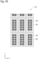
- FIG. 3B is a top view of a portion of the array 300 of FIG. 3A , according to an embodiment.
- each packaged unit 200 can include a separator 350.
- the separator 350 can have a rectangular shape or any other suitable shape(s) or geometry.
- the separator 350 includes an opening to accommodate the packaged unit 200 within the separator 350.
- the separator 350 can have flat surface(s) extending horizontally.
- the separator 350 can be disposed at the level of the fan (e.g., 280 of FIG. 2 ) deck on a top portion of the chiller. That is, a height of the separator 350 and a height of the fan deck of the chiller are the same or almost the same.
- the fans 280 are disposed above the separator 350 and the rest of the chiller is below the separator 350. It will be appreciated that the separator 350 can be disposed at any suitable location.
- the separator 350 can have through holes (not shown) and have a desired amount of porosity to e.g., prevent rain, snow, or the like from accumulating on the separator 350.
- the separator 350 do not have through holes.
- open space(s) can be provided between the separators 350 (see FIGS. 3A and 3B ) to e.g., prevent rain, snow, or the like from accumulating on the separator 350.
- a distance between the openings of adjacent separators 350 or a distance between adjacent packaged units 200 in the Y direction can be at or about 12 feet.
- a distance between the openings of adjacent separators 350 or a distance between adjacent packaged units 200 in the X direction can be at or about 12 feet.
- the Z direction is the height direction of the array 300.
- a distance between the opening of the separator 350 and an edge of the separator 350 or a distance between the packaged unit 200 and an edge of the separator 350 in the Y direction can be at or about 4 feet.
- a distance between the opening of the separator 350 and an edge of the separator 350 or a distance between the packaged unit 200 and an edge of the separator 350 in the X direction can be at or about 4 feet. It will be appreciated that the distance described herein can be any suitable distance.
- ducts can be placed on the outlets of each fan to mitigate air recirculation instead of using the separator 350. Such an embodiment might create excess pressure drop compared with the horizontal separator 350.
- the space(s) between the packaged units 200 can be increased to a maximum allowable spacing to mitigate air recirculation instead of using the separator 350.
- FIG. 4 is a method (or an operational flow chart) 400 to control an array, such as for example the array 300 of FIG. 3A , according to an embodiment.
- the operational flow chart may include one or more operations, actions, or functions depicted by one or more blocks 410, 440, 460, and 480. Although illustrated as discrete blocks, various blocks may be divided into additional blocks, combined into fewer blocks, or eliminated, depending on the desired implementation.
- the description of the method 400 corresponding to the depiction thereof in FIGS. 1-3 and 5-7 performed by the controller(s) described herein (e.g., 220 of FIG. 1 ) or any other suitable controller(s), according to one or more example embodiments described herein, pertains to operating a heating, ventilation, air conditioning, and refrigeration (HVACR) system.
- HVAC heating, ventilation, air conditioning, and refrigeration
- Method 400 includes obtaining an operating condition of the array 300 of packaged units 200 at 410, deriving the operating condition to construct an operating pattern at 440, selecting one or more packaged units 200 in the array 300 to be adjusted to increase efficiency based on the operating pattern at 460; and adjusting the operation of the one or more packaged units selected by the controller at 480.
- a controller e.g., 220 of Fig. 2
- a controller is (or includes, or can be connected to) a specialized computer specifically configured to perform the methods disclosed herein.
- a controller obtains an operating condition of the array 300 of packaged units 200.
- the operating condition can include an ambient temperature of one, more than one, or all of the packaged units 200 in the array 300.
- the controller can obtain the ambient temperature(s) with the corresponding location of the packaged unit 200 within the array 300.
- an entering temperature e.g., entering water temperature or the like
- a coil temperature can be used to derive the ambient temperature or used as a proxy of the ambient temperature.
- the entering temperature can be obtained/determined in real-time (e.g., via a temperature sensor or the like) and can be the temperature of a fluid entering a heat exchanger (e.g., condenser 240 to condense the working fluid, a chiller, or the like) of a packaged unit 200 to exchange thermal energy with the working fluid.
- a heat exchanger e.g., condenser 240 to condense the working fluid, a chiller, or the like
- sensors such as temperature sensors (for ambient temperature), wind speed sensors (e.g., airometer, anemometer, wind-gauge, or the like), wind direction sensors (e.g., wind vanes or the like) can be used to determine the ambient temperature, wind speed/velocity, and wind direction.
- dedicated operating condition sensor(s) can be installed in the packaged units array (e.g., on one or more or all packaged units) to capture the operating condition (e.g., temperature, temperature distribution, wind speed/velocity, wind direction or the like) of the array.
- the operating condition sensor(s) can be one or more temperature sensors, wind speed sensors, wind direction sensors, flow sensor(s), or the like.
- the flow sensor(s) can measure the speed, the direction, or both of an ambient fluid flowing over the flow sensor(s).
- the operating condition sensor(s) can be installed on one or more or all of the packaged units in the array or near the packaged units in the array (e.g., at a location between the packaged units, on the flooring of the rooftop, or the like).
- each packaged unit of the packaged units array can include a temperature sensor (e.g., to determine the ambient temperature), the temperature sensors form an array, and the ambient temperatures determined for the packaged units array can be used to estimate or model the wind speed/velocity and/or wind direction.
- some packaged units of the packaged units array can include temperature sensors forming a temperature sensor grid, and the ambient temperatures determined for the packaged units can be used to estimate or model the wind speed/velocity and/or wind direction.
- one or more wind speed sensors and/or one or more wind direction sensors can be deployed to determine the wind speed/velocity and/or wind direction.
- one temperature sensor, one wind speed sensor, and one wind direction sensor can be deployed to help determining the heat/cool map.
- the packaged unit can run on full load, partial load, variable speed, staging, on, or off, to meet the leaving temperature setpoint (e.g., leaving water temperature or the like) or requirement.
- the fluid can be an ambient fluid, such as the air flowed by the wind through the array 300.
- the entering temperature can be the temperature of a heat transfer fluid (e.g., water or water solution in a water chilling system).
- the heat transfer fluid can be used as a medium for the working fluid indirectly exchange thermal energy with the ambient fluid.
- the entering temperature can correlate with the ambient temperature of the ambient fluid.
- the coil temperature can be the temperature of the coil (e.g., coil 250 of FIG. 2 ) that correlates with the ambient temperature of the ambient fluid (e.g., outdoor air).
- the operating condition can include the shape of the array 300, the size of the array 300, the orientation of the array 300, and/or the spacing between the packaged units 200.
- the shape of the array 300 can be pattern such as a grid, a staggered arrangement, an irregular arraignment, or a combination thereof.
- the orientation of the array 300 can be a direction of the packaged unit relative the array 300.
- the packaged unit can have a rectangular housing.
- the long direction of the rectangular housing can be a first direction of the packaged unit.
- the array 300 can have a rectangular pattern.
- the longer direction of the rectangular pattern can be a second direction.
- the orientation of the array 300 can be the relative direction between the first direction and the second direction.
- the orientation of the packaged unit is the same with the orientation of the array when the first and the second directions are the same direction.
- the orientation of the array is relative to and can be determined based on e.g., the building and/or the prevailing or actual wind.
- the size of the array 300 can be the number of the packaged units 200 in the array 300.
- the spacing can be a distance between adjacent packaged units 200, e.g., between separators 350.
- the controller 220 can include a power meter to obtain energy consumption of one or more of the packaged units 200 in the array 300. In some embodiments, the controller 220 can obtain the energy consumption (e.g., in kilowatts per hour) of a packaged unit 200 with its corresponding location within the array 300.
- the energy consumption e.g., in kilowatts per hour
- the controller 220 can include an output monitor to obtain an operation or operating load (e.g., in tons, percentage of the maximum operating load, being on, being off, being partially off, or the like) of a packaged unit 200.
- the controller 220 can obtain the operating load of a packaged unit 200 with its location within the array 300.
- the controller 220 can determine energy consumption (in the unit of Kw/ton) for chilling, via e.g., power monitors (e.g., to determine energy from the power grid or from diesel gensets).
- the controller 220 can also estimate or determine the power consumed by the packaged unit and/or how many tons of cooling capacities are generated at any given time.
- the controller 220 can obtain an operating mode of a packaged unit 200.
- An operating mode can include a heating mode, a cooling mode, a dehumidification mode, or the like.
- the heating mode can include the array 300 providing thermal energy into the conditioned space by absorbing thermal energy from the ambient fluid.
- the cooling mode can include the array 300 releasing thermal energy to the ambient fluid.
- the dehumidification mode can include the array 300 removing moisture in conditioned space by condensing water vapor from the conditioned space.
- the controller 220 can obtain the operating mode of a packaged unit 200 with its location within the array 300.
- the controller 220 can obtain a load requirement (e.g., in tons) from the conditioned space.
- a load requirement e.g., in tons
- the load requirement can be provided by temperature controller (e.g., a thermostat) in the conditioned space.
- Block 410 may be followed by block 440.
- the controller 220 can derive the operating condition of the array 300 to construct an operating pattern.
- the operating pattern can include a heat map, a wind direction, and/or a wind speed, and/or the like.
- the controller 220 can construct a heat map by arranging the ambient temperature obtained from the packaged units 200 according to their locations within the array 300.
- the heat map can show the ambient temperatures local to the packaged units 200 in the array 300, providing the temperature distribution of the ambient temperature over the array 300.
- the controller 220 can derive a wind direction according to the operating condition. For example, in a cooling operation, the packaged units 200 heats the ambient fluid. The ambient temperature or the entering temperature increases in the direction of the airflow or the wind direction. The controller 220 can derive the wind direction from the direction of temperature increase.
- the controller 220 can derive a wind speed according to the operating condition. For example, in a cooling operation, the packaged units 200 heats the ambient fluid. The ambient temperature or the entering temperature increases more rapidly when the wind speed is slower and less rapidly when the wind speed is faster. Accordingly, the controller 220 can derive a wind speed from the rate of temperature increase. It is appreciated that one or more ambient fluid sensor(s) can measure ambient fluid (e.g., wind, air, or the like) velocity, speed, and/or direction, and allow the controller to capture the wind speed and/or direction directly from the ambient fluid sensor(s). Block 440 may be followed by block 460.
- ambient fluid e.g., wind, air, or the like
- the controller 220 can determine or select one or more packaged units to be adjusted.
- the controller 220 can adjust the operation of the packaged units to turn on, off, or partially on or partially off one or more of the packaged units.
- packaged units 200 can release heat into the ambient fluid.
- a first packaged unit can heat the ambient fluid provide to a second packaged unit, increasing the ambient temperature and/or the entering temperature of the second packaged unit.
- Packaged units are generally optimized to operate most efficiently at a temperature within a temperature range. When the ambient fluid is heated by the first packaged unit above the temperature range, the second packaged unit can be operating less efficiently, consuming more energy.
- the ambient temperature of the second packaged unit can be lowered into the range where the second packaged unit can operate more efficiently.
- the efficiency regained by the second packaged unit can be compensated for reducing of output from the first packaged unit.
- a third packaged unit for example, being away from the first and/or the second packaged unit can be adjusted to provide more operating load to compensate for the reduced output from the first packaged unit.
- the third packaged unit can be a redundant packaged unit. It is appreciated that the array 300 can be configured to include one or more redundant packaged units.
- the controller can determine or select one or more packaged units to be adjusted according to the operating pattern obtained or determined at 440.
- a selection algorithm can, for example, be preprogramed into the controller 220 according to the heat map, the wind direction, and/or the wind speed.
- the algorithm can be determined, for example, by computational fluid dynamics analysis of varies patterns, sizes, and/or orientation of the array, wind direction and/or speed, ambient temperature, or the like. Simulations can, given an operating condition and/or an operating pattern, determine one or more packaged units to be turned on, turned off, or turned partially on or off.
- the simulation can determine the packaged units by optimizing for minimum energy consumption, for example, by lessening ambient temperature hot spot or cold spot in the heat map.
- a hot spot can be the operating condition (e.g., ambient temperature) over a packaged unit being above a threshold level.
- the threshold level can be a threshold temperature above which the packaged units will become less efficient.
- a cold spot can be operating condition (e.g., ambient temperature) over a packaged unit being below a threshold level.
- the threshold level can be a threshold temperature below which the packaged units (e.g., heat pump) will become less efficient.
- the threshold can a predetermined value provided, for example, by the known design and manufacture of the packaged unit.
- the threshold can be a variable correlated with the operating condition of the packaged unit(s) in the array.
- the selection rules can be saved in the controller such that, when the same operating condition and/or operating pattern is detected in operating, the controller can select the one or more packaged unit to be adjusted. Then, the controller can adjust the one or more packaged unit selected based on the operating condition and/or the operating pattern.
- the algorithm can be predetermined according to the simulations.
- An algorithm being predetermined can select and adjust the packaged units to conserve energy without requiring computational fluid dynamics analysis onsite and/or in real-time.
- the algorithm can be determined, for example, by computational fluid dynamics analysis, onsite and/or in real-time to optimize energy consumption.
- FIGS. 5-7 show computational fluid dynamics diagrams (CFDs) of the array 300 of FIG.3A with prevailing or actual winds, according to some embodiments.
- CFD simulation can be used to provide guidance on array 300 installations with a large number of packaged units.
- the installation can be at a data center, on the roof of or around a building, and near heat sources (e.g., genset or the like).
- the large number of packaged units can be, for example, over one hundred packaged units, over one hundred and eighty packaged units, over three hundred packaged units, or the like.
- the packaged units can be included in one or more clusters.
- Each of the clusters can have different operating condition and/or operating patterns from one another, for example, due to obstruction (e.g., a wall, a building, or the like) altering flow of the ambient fluid.
- obstruction e.g., a wall, a building, or the like
- multiple heat/cool maps and/or hot/cold spots can be determined for the clusters, respectively, and embodiments disclosed herein can be applicable to each cluster.
- the CFD simulation can provide guidelines on unit spacing in response to e.g., wind direction, velocity/speed, or the like.
- the array 300 is in a cooling mode releasing thermal energy into the environment, heating the ambient fluid flowing over the array 300.
- a wind can blow from south (i.e., bottom of the page) to north (i.e., top of the page) moving outdoor air flowing over the array 300 and removing thermal energy from the array 300.
- the temperature distribution of the ambient fluid over the array 300 can change. For example, in a cooling mode, removing extreme hot spots in the ambient fluid over the array 300 can increase efficiency of the array 300. As shown in the CFDs of FIGS. 5-7 , darker gray indicates a higher temperature, and lighter gray indicates a lower temperature.
- the packaged units at 500 can be turned off.
- the extreme hot spot 510 can be a result of larger clusters of upstream packaged units releasing heat into the ambient fluid.
- the packaged units at 600 are turned off, lowering the temperature at location 610 slightly.
- raising the temperature at location 620 can still maintain the efficiency at location 620 but cannot improve the efficiency of the packaged units at 610.
- FIG.7 instead of leaving off the packaged units at 500 in FIG. 5 or 600 in FIG.
- the packaged units at 700 are turned off.
- the packaged units 700 can be a center column of the packaged units within in array 300.
- the direction of columns can be the same direction of flow of the ambient fluid (e.g., wind direction).
- the temperature at or around 710 are further lowered, for example, compared to the location 610 in FIG. 6 and location 610 in FIG. 5 . Accordingly, turning off the packaged units 200 at location 710 can be more effective compared to turning off the packaged units at locations of 510 and/or 610, increasing the efficiency of the array 300.
- the operating condition used for deriving an operating map as disclosed herein may comprise one or more operating conditions. Accordingly, when the operating condition comprises one or more operating conditions, an alternative definition would be that an operating map is derived based on one or more operating conditions.
- an operating pattern spatially relates a thermal or flow parameter (such as a temperature or velocity) associated with the packaged units to provide a pattern such as a heat map, wind speed, a wind direction and the like).
- the operating pattern may therefore be considered to define a thermal or flow parameter in spatial relation to the array of packaged units.
- Embodiments disclosed herein can determine distribution of the wind and/or temperature around the packaged units, to actively, intelligently, and/or selectively shut down a preferred or selected bank of packaged units that are not needed and/or redundant and that get more hot (or cold) air than others, depending on wind conditions such as how the wind is blowing (direction and velocity) and/or weather conditions such as ambient temperature, to provide an overall higher efficiency for the site. It will be appreciated that shutting down packaged units can alter or change the temperature distribution around the packaged units.
- Embodiments disclosed herein can optimize the packaged units array for a given weather conditions, strategically control large array of packaged units, and use the lowest or least amount of energy (for a given condition) possible to run the appropriate packaged units in the array.
- Embodiments disclosed herein can determine the size, number, and/or location of subarray of packaged units to be shut down based on the condition of the wind, the condition of the temperature (e.g., local entering temperature of each packaged unit), and the condition of the array (shape, size, and/or orientation), to provide overall higher efficiency for the site and to improve energy efficiency.
- Embodiments disclosed herein can increase efficiency of the array under moderate ambient fluid condition, such as, intermediate wind speed over the array. Such efficiency gain is a result from unexpected results obtained during the experiments for chillers array. Typically, worst cases of efficiency of the packaged units array may be in conditions such as lowest wind speed (e.g., for heat pumps or the like) or highest wind speed. However, experiments show unexpected results for chillers arrays, where intermediate wind speed actually causes hot/cold spot issues. For example, at a wind speed lower than a first threshold level, heat released from the array rises with the heated air, leaving the array.
- an intermediate wind speed can be a wind speed between the first and second threshold levels.
- a heating, ventilation, air conditioning, and refrigeration (HVACR) system comprising:
- Aspect 2 The HVACR system of aspect 1, wherein the operating condition comprises an entering temperature of at least one packaged units of the array of packaged units.
- Aspect 3 The HVACR system of any one of aspect 1 or aspect 2, wherein the operating condition comprises a coil temperature of at least one packaged units of the array of packaged units.
- Aspect 4 The HVACR system of any one of aspects 1-3, wherein the array of packaged units comprises:
- Aspect 5 The HVACR system of any one of aspects 1-4, wherein the operating condition comprises:
- Aspect 6 The HVACR system of any one of aspects 1-5, wherein the operating pattern comprises:
- Aspect 7 The HVACR system of any one of aspects 1-6, wherein the controller is configured to adjust by turning off the one or more packaged units of the array of packaged units.
- Aspect 8 The HVACR system of any one of aspects 1-7, wherein
- Aspect 9 The HVACR system of any one of aspects 1-8, wherein the array of packaged units is an array of air-cooled chillers.
- a method of operating a heating, ventilation, air conditioning, and refrigeration (HVACR) system comprising:
- Aspect 11 The method of operating the HVACR system of aspect 10, wherein the operating condition comprises an entering temperature of at least one packaged unit of the array of packaged units.
- Aspect 12 The method of operating the HVACR system of any one of aspect 10 or aspect 11, wherein the operating condition comprises a coil temperature of at least one packaged unit of the array of packaged units.
- Aspect 13 The method of operating the HVACR system of any one of aspect 10-12, wherein the operating condition comprises a conditioning load required by a conditioned space conditioned by the array of packaged units.
- Aspect 14 The method of operating the HVACR system of any one of aspect 10-13, wherein the operating condition comprises:
- Aspect 15 The method of operating the HVACR system of any one of aspect 10-14, wherein the operating pattern comprises:
- Aspect 17 The method of operating the HVACR system of any one of aspect 10-15, wherein adjusting the one or more of the array of packaged units comprises turning off the one or more of the array of packaged units.
- Aspect 18 The method of operating the HVACR system of any one of aspect 10-16, wherein
- Aspect 19 The method of operating the HVACR system of any one of aspect 10-17, wherein the array of packaged units includes one or more redundant packaged units, and adjusting the one or more of the array of packaged units further comprises turning on at least one of the one or more redundant unit.
- Aspect 20 The method of operating the HVACR system of aspect 15, wherein the heat map is constructed from an entering temperature of one or more packaged units of the array of packaged units.
Landscapes
- Engineering & Computer Science (AREA)
- Signal Processing (AREA)
- Mechanical Engineering (AREA)
- General Engineering & Computer Science (AREA)
- Chemical & Material Sciences (AREA)
- Combustion & Propulsion (AREA)
- Physics & Mathematics (AREA)
- Fuzzy Systems (AREA)
- Mathematical Physics (AREA)
- Fluid Mechanics (AREA)
- Life Sciences & Earth Sciences (AREA)
- Sustainable Development (AREA)
- Air Conditioning Control Device (AREA)
Abstract
Description
- This disclosure relates generally to a heating, ventilation, air conditioning, and refrigeration (HVACR) system having an array of packaged units to condition a space. More specifically, the disclosure relates to controls and methods for adjusting the operation of one or more packaged units of the array of the packaged units to improve performance and efficiency and to reduce energy consumption of the array in conditioning the space.
- A heating, ventilation, air conditioning, and refrigeration (HVACR) system may include a group of rooftop units installed on the rooftop of a building. The rooftop units can include one or more heat exchangers to facilitate thermal energy exchange between a heat transfer fluid and the outdoor air. The heat transfer fluid can be part of a fluid circuit to condition indoor air. A fan can move the conditioned indoor air in an air distribution system to condition the entire building. The group of rooftop units can change the temperature profile of the outdoor air over the group. For example, in a cooling operating where the rooftop units release heat into outdoor air, the upstream rooftop units in the group can exhaust heat into the outdoor air, heating up the intake temperature of a downstream rooftop unit in the same group and decreasing the efficiency of the downstream rooftop unit.
- This disclosure relates generally to a heating, ventilation, air conditioning, and refrigeration (HVACR) system having an array of packaged units (e.g., air cooled chillers, direct free cooling chillers, air handling units, air conditioning outdoor units, heat pumps, air-cooled condensers or condenser coils, or the like) to condition a space. More specifically, the disclosure relates to controls and methods for adjusting the operation of one or more packaged units of the array of the packaged units to improve performance and efficiency and to reduce energy consumption of the array in conditioning the space.
- The array of packaged units exchanges thermal energy with an ambient fluid in the environment. For example, when providing cooling to the conditioned space, the array of packaged units can exhaust heat to the ambient fluid, such as air flowed by the wind in the environment. Upstream units can be some packaged units of the array disposed upstream from some other packaged units of the array relative to a flow direction of the ambient fluid (e.g., wind direction). Downstream units can be some packaged units of the array disposed downstream from some other packaged units of the array relative to the flow direction of the ambient fluid.
- The ambient fluid flows through the upstream units and can remove heat from the upstream units. The heat can increase the temperature of the ambient fluid exhausted from the upstream units, heating the ambient fluid flows to some of the downstream units.
- Generally, packaged units can operate most efficiently when receiving ambient fluid at a temperature within a desired temperature range. When the downstream units receive ambient fluid above this temperature range (e.g., heated by the upstream units), the downstream units are susceptible to operating less efficiently, consuming more energy, and lowering the overall efficiency of the array. Accordingly, by adjusting the operation (e.g., turning off, shutting down, or the like) of some of the packaged units such that the temperature of the ambient fluid received by the downstream units is lowered, the overall efficiency of the array can be improved. For example, adjusting the operation of the packaged units can include increasing the operating load, decreasing the operating load, turning on, turning off, turning partially off, or the like.
- It is appreciated that an array of packaged units providing heating, cooling, dehumidification, or the like, or a combination thereof, can benefit from adjusting the operation of one or more packaged units within the array to regulate the ambient fluid received by the downstream units. For example, when providing heating to the conditioned space, the array of packaged units can absorb heat from the ambient fluid. Upstream units absorbing heat can cool the ambient fluid received by downstream units to a temperature lower than the temperature range efficient for the packaged units. Accordingly, by adjusting or turning off some packaged units such that the temperature of the ambient fluid received by the downstream units is increased into the temperature range, the overall efficiency of the array can be improved.
- In some embodiments, a heating, ventilation, air conditioning, and refrigeration (HVACR) system, includes an array of packaged units; and a controller configured to obtain an operating condition of the array of packaged units, derive the operating condition to construct an operating pattern, select one or more packaged units to be adjusted to increase efficiency of the array of packaged units based on the operating pattern, and to adjust operation of the one or more packaged units selected by the controller.
- In some embodiments, a method of operating a HVACR system includes obtaining an operating condition of an array of packaged units; deriving the operating condition to construct an operating pattern; selecting one or more packaged units in the array of packaged units to be adjusted to increase efficiency based on the operating pattern; and adjusting operation of the one or more packaged units selected by the controller.
- References are made to the accompanying drawings that form a part of this disclosure and which illustrate the embodiments in which systems and methods described in this specification can be practiced.
-
FIG. 1 illustrates a schematic diagram of a refrigeration circuit, which may be implemented in an HVACR system, according to an embodiment. -
FIG. 2 is a schematic view of a packaged unit, according to an embodiment. -
FIG. 3A is a perspective view of an array of packaged units, according to an embodiment. -
FIG. 3B is a top view of a portion of the array ofFIG. 3A , according to an embodiment. -
FIG. 4 shows a control method of the array ofFIG. 3A , according to an embodiment. -
FIG. 5 shows a computational fluid dynamics diagram of the array ofFIG.3A , according to an embodiment. -
FIG. 6 shows a computational fluid dynamics diagram of the array ofFIG.3A , according to another embodiment. -
FIG. 7 shows a computational fluid dynamics diagram of the array ofFIG.3A , according to yet another embodiment. - Like reference numbers represent like parts throughout.
- In the following detailed description, reference is made to the accompanying drawings, which form a part of the description. In the drawings, similar symbols typically identify similar components, unless context dictates otherwise. Furthermore, unless otherwise noted, the description of each successive drawing may reference features from one or more of the previous drawings to provide clearer context and a more substantive explanation of the current example embodiment. Still, the example embodiments described in the detailed description, drawings, and claims are not intended to be limiting. Other embodiments may be utilized, and other changes may be made, without departing from the spirit or scope of the subject matter presented herein. It will be readily understood that the aspects of the present disclosure, as generally described herein and illustrated in the drawings, may be arranged, substituted, combined, separated, and designed in a wide variety of different configurations, all of which are explicitly contemplated herein.
- Particular embodiments of the present disclosure are described herein with reference to the accompanying drawings; however, it is to be understood that the disclosed embodiments are merely examples of the disclosure, which may be embodied in various forms. Well-known functions or constructions are not described in detail to avoid obscuring the present disclosure in unnecessary detail. Therefore, specific structural and functional details disclosed herein are not to be interpreted as limiting, but merely as a basis for the claims and as a representative basis for teaching one skilled in the art to variously employ the present disclosure in virtually any appropriately detailed structure. In this description, as well as in the drawings, like-referenced numbers represent elements that may perform the same, similar, or equivalent functions.
- Additionally, the present disclosure may be described herein in terms of functional block components and various processing steps. It should be appreciated that such functional blocks may be realized by any number of hardware and/or software components configured to perform the specified functions.
- The scope of the disclosure should be determined by the appended claims and their legal equivalents, rather than by the examples given herein. For example, the steps recited in any method claims may be executed in any order and are not limited to the order presented in the claims. Moreover, no element is essential to the practice of the disclosure unless specifically described herein as "critical" or "essential."
- In some embodiments, hot (or cold) air exhaust from operating packaged units (e.g., air cooled chillers) can recirculate and result in higher (or lower) than ambient temperatures at coil entering air surfaces, causing a decrease in capacity and efficiency, which may result in packaged units going off line due to high (or low) entering air temperatures. Such issues can correlate with the number of packaged units, packaged unit layout, customer features such as walls or separators, generators, prevailing (or actual) wind speed/velocity and/or direction, or the like. Embodiments disclosed herein can provide tuning of the packaged units staging (e.g., turning on or off selected packaged units) based on the above factors to optimize overall site packaged units performance. In particular, the tuning is beneficial if there is packaged units redundancy and/or the site load is not at maximum.
-
FIG. 1 is a schematic diagram of arefrigerant circuit 100, according to an embodiment. Therefrigerant circuit 100 can include acompressor 120, acondenser 140, anexpander 160, and anevaporator 180. Therefrigerant circuit 100 may also include a controller (e.g., thecontroller 220 ofFIG. 2 ) configured to control the operations of thecompressor 120, thecondenser 140, theexpander 160, and/or theevaporator 180. - The
refrigerant circuit 100 can generally be applied in a variety of systems used to control an environmental condition (e.g., temperature, humidity, air quality, or the like) in a conditioned space. The conditioned space can be a space within an office building, a commercial building, a factory, a laboratory, a data center, a residential building, or the like. In an embodiment, therefrigerant circuit 100 can be configured to be a cooling system (e.g., an air conditioning system) capable of operating in a cooling mode. In an embodiment, therefrigerant circuit 100 can be configured to be a heat pump that can operate in a heating/defrost mode. It is appreciated that therefrigerant circuit 100 can configured to operate in a cooling mode and a heating/defrosting mode, - The
compressor 120, thecondenser 140, theexpander 160, and theevaporator 180 can be fluidly connected. An "expander" as described herein may also be referred to as an expansion device. In an embodiment, theexpander 160 can be an expansion valve, expansion plate, expansion vessel, orifice, or the like, or other such types of expansion mechanisms. It should be appreciated that theexpander 160 may be any suitable type of expander used in the field for expanding a working fluid to cause the working fluid to decrease in pressure and temperature. - The
refrigerant circuit 100 is an example and can be configured to include more or less components. For example, in an embodiment, therefrigerant circuit 100 can include other components such as, but not limited to, an economizer heat exchanger, one or more flow control devices (e.g., a valve, a pump, etc.), a receiver tank, a dryer, a suction-liquid heat exchanger, or the like. - The
refrigerant circuit 100 can operate according to generally known principles. Therefrigerant circuit 100 can be configured to heat and/or cool a liquid process fluid. The liquid process fluid can be a heat transfer fluid or medium (e.g., a liquid such as, but not limited to, water or the like). Therefrigerant circuit 100 may be generally representative of a liquid chiller system. Therefrigerant circuit 100 can alternatively be configured to heat and/or cool a gaseous process fluid (e.g., a heat transfer medium or fluid (e.g., a gas such as, but not limited to, air or the like), in which case therefrigerant circuit 100 may be generally representative of an air conditioner and/or heat pump. - In some embodiments, the
refrigerant circuit 100 can operate as a vapor-compression circuit such that thecompressor 120 compresses a working fluid (e.g., a heat transfer fluid such as, but not limited to, refrigerant or the like) from a relatively lower pressure gas to a relatively higher-pressure gas. The relatively higher-pressure gas is at a relatively higher temperature, being discharged from thecompressor 120 and flowing through thecondenser 140. In accordance with generally known principles, the working fluid flows through thecondenser 140 and rejects heat to the process fluid (e.g., water, air, etc.), thereby cooling the working fluid. The cooled working fluid, which is now in a liquid form, flows to theexpander 160 that can reduce the pressure of the working fluid. As a result, a portion of the working fluid is converted to a gaseous form. The working fluid, which is now in a mixed liquid and gaseous form flows to theevaporator 180. The working fluid flows through theevaporator 180 and absorbs heat from the process fluid (e.g., a heat transfer medium such as, but not limited to, water, a solution, air, etc.), heating the working fluid, and converting it to a gaseous form. The gaseous working fluid then returns to thecompressor 120. The above-described process continues while the heat transfer circuit is operating, for example, in a cooling mode (e.g., while thecompressor 120 is enabled). - In some embodiments, the
refrigerant circuit 100 can be configured to operate as a free cooling/heating circuit to control one or more environmental conditions of the conditioned space. A free cooling/heating circuit can include a first heat exchanger and a second heat exchanger fluidly connected by a working fluid. The first and second heat exchangers of the free cooling/heating circuit can be dedicated heat exchangers in addition to therefrigeration circuit 100 having thecompressor 120, thecondenser 140, theexpander 160, and theevaporator 180. In some embodiments, the first and second heat exchangers can share, for example, thecondenser 140 and theevaporator 180 such that therefrigeration circuit 100 can operate as a free cooling/heating circuit or a vapor compression circuit. - In some embodiments, the first heat exchanger can exchange thermal energy between a working fluid and an ambient fluid (e.g., outdoor air). The first exchanger can be disposed in a location suitable to exchange thermal energy with the ambient fluid. The location can include a rooftop of the conditioned space. The second heat exchanger can be the evaporator 180 to exchange thermal energy between the working fluid and fluid in the conditioned space. Fluid in the conditioned space can, for example, be indoor air. In some embodiments, the first heat exchanger can be the
condenser 140. - In a cooling operation, the first heat exchanger can release thermal energy to the ambient fluid and cool the working fluid. A pump can move the cooled working fluid to the second heat exchanger to exchange thermal energy with the fluid in the conditioned space, heating the working fluid to be cooled by the ambient fluid again. In some embodiments, in a cooling operation, the ambient fluid can have a temperature lower than the temperature of the fluid in the conditioned space. In a heating operating, the pump can circulate the working fluid between the first and the second heat exchangers to move thermal energy from the ambient fluid to the fluid in the conditioned space. In some embodiments, in a heating operation, the ambient fluid can have a temperature higher than the temperature of the fluid in the conditioned space. The working fluid can be any heat transfer fluid such as a refrigerant, water, a water solution, glycol fluid, or the like.
-
FIG. 2 is a schematic view of a packagedunit 200, according to an embodiment. The packagedunit 200 can be any piece of HVACR equipment that exchanges thermal energy with the environment, for example, by absorbing or releasing thermal energy with an ambient fluid (e.g., outdoor air). The packagedunit 200 can include at least a portion of a fluid circuit to transfer thermal energy from the packagedunit 200 to the conditioned space. In some embodiments, the fluid circuit can be a heat transfer circuit (such as, for example, as shown inFIG. 1 ) that is configured to be a free cooling/heating circuit, a vapor-compression circuit, or the like, or a combination thereof. In an embodiment, the packagedunit 200 ofFIG. 2 can be an air cooled chiller, a free cooling chiller (e.g., a direct free cooling chiller), an air handling unit, an air conditioning outdoor unit, a heat pump, an air-cooled condenser or condenser coil, or the like. - The air cooled chiller can include at least one heat exchanger disposed therein. The heat exchanger facilitates heat exchanging between air and a fluid circuit. The circuit can be a free heating/cooling circuit or a vapor-compression circuit to provide environmental control to a controlled space. In some embodiments, the air cooled chiller can include a free cooling circuit configured to cool the condenser in a vapor-compression circuit. The free cooling circuit can include a liquid-air heat exchanger to cool the condenser.
- The air handling unit can include a fan or blower to move conditioned air through an air distribution system to condition the conditioned space. The air handling unit can include an air outlet that can release air into the environment. For example, the air outlet can be an outlet of a heat exchanger configured to condense a working fluid, releasing an exhaust that is heated above the ambient temperature.
- The air conditioning outdoor unit can include a condenser configured to condense a refrigerant in a fluid circuit. A fan of the air conditioning outdoor unit can force the ambient fluid, such as outdoor air, through the condenser to remove thermal energy from the condenser. The air conditioning outdoor unit can be fluidly connected with an evaporator, an expander, and a compressor to form the fluid circuit. The fluid circuit can include a vapor-compression circuit. It is appreciated that the evaporator, the expander, and/or the compressor may or may not be contained within the same housing of the air conditioning outdoor unit. In some embodiments, the heat pump can include an evaporator configured to evaporate a refrigerant fluidly connecting a condenser, a compressor, and an expander with the evaporator in a refrigeration circuit.
- The heat pump can include an evaporator configured to evaporate a refrigerant in a fluid circuit. A fan of the heat pump can force the ambient fluid, such as outdoor air, through the evaporator to provide thermal energy to evaporate the refrigerant. The heat pump can be fluidly connected with a condenser, an expander, and a compressor to form the fluid circuit. The fluid circuit can include a vapor-compression circuit. It is appreciated that the condenser, the expander, and/or the compressor may or may not be contained within the same housing of the heat pump.
- The packaged
unit 200 can include a housing (or enclosure) 201 configured to contain one or more HVACR system equipment, such as thecompressor 120, thecondenser 140, theexpander 160, and theevaporator 180 of therefrigeration circuit 100 ofFIG. 1 . - As shown in
FIG. 2 , thehousing 201 of the packagedunit 200 can contain acompressor 210, anevaporator 230, acondenser 240, acontroller 220, and one ormore panels 270. Thecondenser 240 is connected to anair coil 250 and one ormore fans 280. In an embodiment, thecompressor 210 can be a fixed speed or variable speed compressor to compress a working fluid. Thefans 280 can be single speed or variable speed and/or fans with a multiple number of fan stages or discrete steps to move air, for example, through theair coil 250. Thepanels 270 can be configured to be removable to provide access to thehousing 201. - The
condenser 240 and itsair coil 250 in the embodiment shown are one example of an air cooled condenser, however, it will be appreciated that thespecific condenser 240/coil 250 combination shown is merely exemplary. - The packaged
unit 200 can be considered as a single unit within the HVAC system and be supported by aframe 260. It will be appreciated that the specific configuration shown inFIG. 2 is merely exemplary, as other packaged designs, layouts, and specific configurations may be employed. - It will be appreciated that the
controller 220 can include a processor (not shown), a memory (not shown), and optionally a clock (not shown) and an input/output (I/O) interface (not shown). Thecontroller 220 can be configured to receive data as input from various components within the HVACR system, such as the components shown inFIG. 1 andFIG. 2 , and can also send command or control signals as output to various components within of the HVACR system. For example,controller 220 can be a central controller in communication with one or more of the packagedunits 200 in thearray 300, and can be configured to control the operation of one or more of the packagedunits 200. Thecontroller 220 can be configured to communicate with or control the packagedunits 200 or other components in the system utilizing any suitable communications including power line communications, Pulse Width Modulation (PWM) communications, Local Interconnect Network (LIN) communications, Controller Area Network (CAN) communications, or the like. The communications can include wired and/or wireless, analog and/or digital communications. In one embodiment, the communication can include communications over telematics. -
FIG. 3A is a perspective view of anarray 300 of packagedunits 200, according to an embodiment. Thearray 300 can include one or more packagedunits 200 arranged in a pattern. As illustrated, thearray 300 can include twenty packagedunits 200 arranged in a pattern of a 4 by 5 rectangular grid. It is appreciated that the packagedunits 200 can be arranged in any suitable pattern as, for example, but not limited to, a grid, a circle, irregular, or a combination thereof. It is appreciated that the size of thearray 300 can include any number of the same or different packagedunits 200. For example, all the packagedunits 200 of thearray 300 can each have a full operating load of a first heating or cooling capacity. A full operating load can be the maximum output of the packagedunit 200 as designed by the manufacture of the packagedunit 200. In some embodiments, some of the packagedunits 200 of thearray 300 can have a full operating load larger, equal to, or smaller than the first heating or cooling capacity. In some embodiments, one or more of the packagedunits 200 can operate in full or partial load of the full operating load. Operating under a partial load can be caused by a controller (e.g., controller 220) or inefficiencies due to, for example, ambient temperature being outside a temperature range most efficient for the packaged unit. - The
array 300 of packagedunits 200 can provide a conditioning load larger than a single packagedunit 200, for example, for a conditioned space requires a larger conditioning load. - It is appreciated that the exhaust of some of the packaged
units 200 in thearray 300 can affect the operating condition of some other of the packagedunits 200 in thearray 300. In some embodiments, the ambient fluid can flow in a direction W. The ambient fluid can be outdoor air flowed by the wind. Affecting the operating condition can include, for example, increasing or reducing an ambient temperature above or below a temperature range efficient for the packagedunits 200. -
Upstream units 200A anddownstream units 200B can include one or more packagedunits 200 disposed relative to the wind directionW. Upstream units 200A can create an exhaust that affect the ambient fluid. The exhaust can affect the ambient fluid, for example, by changing the ambient temperature of the ambient fluid at some locations (e.g.,locations FIGS. 5-7 ) over thearray 300. For example, in a cooling mode, theupstream units 200A can create an exhaust that heats the ambient fluid at a location over thedownstream units 200B. Thedownstream units 200B can receive the ambient fluid heated by theupstream units 200A. As a result, thedownstream units 200B can operating at a lowered efficiency because of the ambient temperature of the ambient fluid provided to thedownstream units 200B are outside the temperature range of which the packagedunits 200 can operate most efficiently. - One or more of the packaged
units 200 can optionally include aseparator 350. In an embodiment, theseparator 350 can be a baffle, a plate, or the like. Theseparator 350 can be configured to eliminate or reduce hot/cold air (e.g., hot/cold discharge air) recirculation of the packaged unit 200 (e.g., at the chiller condenser coil air inlet surfaces, into the chiller condenser coil inlets, or the like). -
FIG. 3B is a top view of a portion of thearray 300 ofFIG. 3A , according to an embodiment. As shown inFIGS 3A and3B , each packagedunit 200 can include aseparator 350. In an embodiment, theseparator 350 can have a rectangular shape or any other suitable shape(s) or geometry. Theseparator 350 includes an opening to accommodate the packagedunit 200 within theseparator 350. - In an embodiment, the
separator 350 can have flat surface(s) extending horizontally. In the application where the packagedunit 200 is a chiller (e.g., an air-cooled chiller or the like), theseparator 350 can be disposed at the level of the fan (e.g., 280 ofFIG. 2 ) deck on a top portion of the chiller. That is, a height of theseparator 350 and a height of the fan deck of the chiller are the same or almost the same. In such an embodiment, thefans 280 are disposed above theseparator 350 and the rest of the chiller is below theseparator 350. It will be appreciated that theseparator 350 can be disposed at any suitable location. - In an embodiment, the
separator 350 can have through holes (not shown) and have a desired amount of porosity to e.g., prevent rain, snow, or the like from accumulating on theseparator 350. In another embodiment, theseparator 350 do not have through holes. In such an embodiment, open space(s) can be provided between the separators 350 (seeFIGS. 3A and3B ) to e.g., prevent rain, snow, or the like from accumulating on theseparator 350. - As shown in
FIGS. 3A and3B , a distance between the openings ofadjacent separators 350 or a distance between adjacent packagedunits 200 in the Y direction (e.g., a width direction "W" of the array 300) can be at or about 12 feet. A distance between the openings ofadjacent separators 350 or a distance between adjacent packagedunits 200 in the X direction (e.g., a length direction of the array 300) can be at or about 12 feet. It will be appreciated that the Z direction is the height direction of thearray 300. A distance between the opening of theseparator 350 and an edge of theseparator 350 or a distance between the packagedunit 200 and an edge of theseparator 350 in the Y direction can be at or about 4 feet. A distance between the opening of theseparator 350 and an edge of theseparator 350 or a distance between the packagedunit 200 and an edge of theseparator 350 in the X direction can be at or about 4 feet. It will be appreciated that the distance described herein can be any suitable distance. - In another embodiment, ducts can be placed on the outlets of each fan to mitigate air recirculation instead of using the
separator 350. Such an embodiment might create excess pressure drop compared with thehorizontal separator 350. In yet another embodiment, the space(s) between the packagedunits 200 can be increased to a maximum allowable spacing to mitigate air recirculation instead of using theseparator 350. -
FIG. 4 is a method (or an operational flow chart) 400 to control an array, such as for example thearray 300 ofFIG. 3A , according to an embodiment. The operational flow chart may include one or more operations, actions, or functions depicted by one ormore blocks method 400, corresponding to the depiction thereof inFIGS. 1-3 and5-7 performed by the controller(s) described herein (e.g., 220 ofFIG. 1 ) or any other suitable controller(s), according to one or more example embodiments described herein, pertains to operating a heating, ventilation, air conditioning, and refrigeration (HVACR) system. The method may begin atblock 410. -
Method 400 includes obtaining an operating condition of thearray 300 of packagedunits 200 at 410, deriving the operating condition to construct an operating pattern at 440, selecting one or more packagedunits 200 in thearray 300 to be adjusted to increase efficiency based on the operating pattern at 460; and adjusting the operation of the one or more packaged units selected by the controller at 480. In an embodiment, a controller (e.g., 220 ofFig. 2 ) is (or includes, or can be connected to) a specialized computer specifically configured to perform the methods disclosed herein. - At 410, a controller obtains an operating condition of the
array 300 of packagedunits 200. The operating condition can include an ambient temperature of one, more than one, or all of the packagedunits 200 in thearray 300. The controller can obtain the ambient temperature(s) with the corresponding location of the packagedunit 200 within thearray 300. - In some embodiments, an entering temperature (e.g., entering water temperature or the like) and/or a coil temperature can be used to derive the ambient temperature or used as a proxy of the ambient temperature. The entering temperature can be obtained/determined in real-time (e.g., via a temperature sensor or the like) and can be the temperature of a fluid entering a heat exchanger (e.g.,
condenser 240 to condense the working fluid, a chiller, or the like) of a packagedunit 200 to exchange thermal energy with the working fluid. - In an embodiment, when a proxy of the ambient temperature is not available, sensors such as temperature sensors (for ambient temperature), wind speed sensors (e.g., airometer, anemometer, wind-gauge, or the like), wind direction sensors (e.g., wind vanes or the like) can be used to determine the ambient temperature, wind speed/velocity, and wind direction. It is appreciated that dedicated operating condition sensor(s) can be installed in the packaged units array (e.g., on one or more or all packaged units) to capture the operating condition (e.g., temperature, temperature distribution, wind speed/velocity, wind direction or the like) of the array. The operating condition sensor(s) can be one or more temperature sensors, wind speed sensors, wind direction sensors, flow sensor(s), or the like. The flow sensor(s) can measure the speed, the direction, or both of an ambient fluid flowing over the flow sensor(s). In some embodiments, the operating condition sensor(s) can be installed on one or more or all of the packaged units in the array or near the packaged units in the array (e.g., at a location between the packaged units, on the flooring of the rooftop, or the like).
- In an embodiment, each packaged unit of the packaged units array can include a temperature sensor (e.g., to determine the ambient temperature), the temperature sensors form an array, and the ambient temperatures determined for the packaged units array can be used to estimate or model the wind speed/velocity and/or wind direction. In another embodiment, some packaged units of the packaged units array can include temperature sensors forming a temperature sensor grid, and the ambient temperatures determined for the packaged units can be used to estimate or model the wind speed/velocity and/or wind direction.
- In yet another embodiment, in addition to one or more temperature sensors, one or more wind speed sensors and/or one or more wind direction sensors can be deployed to determine the wind speed/velocity and/or wind direction. For example, one temperature sensor, one wind speed sensor, and one wind direction sensor can be deployed to help determining the heat/cool map.
- Depending on the entering temperatures on each packaged unit, the packaged unit can run on full load, partial load, variable speed, staging, on, or off, to meet the leaving temperature setpoint (e.g., leaving water temperature or the like) or requirement. In some embodiments, the fluid can be an ambient fluid, such as the air flowed by the wind through the
array 300. In some embodiments, the entering temperature can be the temperature of a heat transfer fluid (e.g., water or water solution in a water chilling system). The heat transfer fluid can be used as a medium for the working fluid indirectly exchange thermal energy with the ambient fluid. Accordingly, the entering temperature can correlate with the ambient temperature of the ambient fluid. In some embodiments, the coil temperature can be the temperature of the coil (e.g.,coil 250 ofFIG. 2 ) that correlates with the ambient temperature of the ambient fluid (e.g., outdoor air). - In some embodiments, the operating condition can include the shape of the
array 300, the size of thearray 300, the orientation of thearray 300, and/or the spacing between the packagedunits 200. For example, the shape of thearray 300 can be pattern such as a grid, a staggered arrangement, an irregular arraignment, or a combination thereof. The orientation of thearray 300 can be a direction of the packaged unit relative thearray 300. For examples, the packaged unit can have a rectangular housing. The long direction of the rectangular housing can be a first direction of the packaged unit. Thearray 300 can have a rectangular pattern. The longer direction of the rectangular pattern can be a second direction. The orientation of thearray 300 can be the relative direction between the first direction and the second direction. For example, the orientation of the packaged unit is the same with the orientation of the array when the first and the second directions are the same direction. In an embodiment, the orientation of the array is relative to and can be determined based on e.g., the building and/or the prevailing or actual wind. - The size of the
array 300 can be the number of the packagedunits 200 in thearray 300. The spacing can be a distance between adjacent packagedunits 200, e.g., betweenseparators 350. - In some embodiments, the
controller 220 can include a power meter to obtain energy consumption of one or more of the packagedunits 200 in thearray 300. In some embodiments, thecontroller 220 can obtain the energy consumption (e.g., in kilowatts per hour) of a packagedunit 200 with its corresponding location within thearray 300. - In some embodiments, the
controller 220 can include an output monitor to obtain an operation or operating load (e.g., in tons, percentage of the maximum operating load, being on, being off, being partially off, or the like) of a packagedunit 200. In some embodiments, thecontroller 220 can obtain the operating load of a packagedunit 200 with its location within thearray 300. Thecontroller 220 can determine energy consumption (in the unit of Kw/ton) for chilling, via e.g., power monitors (e.g., to determine energy from the power grid or from diesel gensets). Thecontroller 220 can also estimate or determine the power consumed by the packaged unit and/or how many tons of cooling capacities are generated at any given time. - In some embodiments, the
controller 220 can obtain an operating mode of a packagedunit 200. An operating mode can include a heating mode, a cooling mode, a dehumidification mode, or the like. The heating mode can include thearray 300 providing thermal energy into the conditioned space by absorbing thermal energy from the ambient fluid. The cooling mode can include thearray 300 releasing thermal energy to the ambient fluid. The dehumidification mode can include thearray 300 removing moisture in conditioned space by condensing water vapor from the conditioned space. In some embodiments, thecontroller 220 can obtain the operating mode of a packagedunit 200 with its location within thearray 300. - In some embodiments, the
controller 220 can obtain a load requirement (e.g., in tons) from the conditioned space. For example, the load requirement can be provided by temperature controller (e.g., a thermostat) in the conditioned space.Block 410 may be followed byblock 440. - At 440, the
controller 220 can derive the operating condition of thearray 300 to construct an operating pattern. The operating pattern can include a heat map, a wind direction, and/or a wind speed, and/or the like. - For example, the
controller 220 can construct a heat map by arranging the ambient temperature obtained from the packagedunits 200 according to their locations within thearray 300. The heat map can show the ambient temperatures local to the packagedunits 200 in thearray 300, providing the temperature distribution of the ambient temperature over thearray 300. - In some embodiments, the
controller 220 can derive a wind direction according to the operating condition. For example, in a cooling operation, the packagedunits 200 heats the ambient fluid. The ambient temperature or the entering temperature increases in the direction of the airflow or the wind direction. Thecontroller 220 can derive the wind direction from the direction of temperature increase. - In some embodiments, the
controller 220 can derive a wind speed according to the operating condition. For example, in a cooling operation, the packagedunits 200 heats the ambient fluid. The ambient temperature or the entering temperature increases more rapidly when the wind speed is slower and less rapidly when the wind speed is faster. Accordingly, thecontroller 220 can derive a wind speed from the rate of temperature increase. It is appreciated that one or more ambient fluid sensor(s) can measure ambient fluid (e.g., wind, air, or the like) velocity, speed, and/or direction, and allow the controller to capture the wind speed and/or direction directly from the ambient fluid sensor(s).Block 440 may be followed byblock 460. - At 460, the
controller 220 can determine or select one or more packaged units to be adjusted. Thecontroller 220 can adjust the operation of the packaged units to turn on, off, or partially on or partially off one or more of the packaged units. For example, in a cooling operation, packagedunits 200 can release heat into the ambient fluid. As the packagedunits 200 being disposed in anarray 300, a first packaged unit can heat the ambient fluid provide to a second packaged unit, increasing the ambient temperature and/or the entering temperature of the second packaged unit. Packaged units are generally optimized to operate most efficiently at a temperature within a temperature range. When the ambient fluid is heated by the first packaged unit above the temperature range, the second packaged unit can be operating less efficiently, consuming more energy. By adjusting the operation of the first packaged unit to lessen the heating of the ambient fluid provided to the second packaged unit, the ambient temperature of the second packaged unit can be lowered into the range where the second packaged unit can operate more efficiently. In some embodiment, when the first packaged unit is adjusted, for example, to lower the operating load, the efficiency regained by the second packaged unit can be compensated for reducing of output from the first packaged unit. In some embodiments, a third packaged unit, for example, being away from the first and/or the second packaged unit can be adjusted to provide more operating load to compensate for the reduced output from the first packaged unit. The third packaged unit can be a redundant packaged unit. It is appreciated that thearray 300 can be configured to include one or more redundant packaged units. - The controller (e.g., 220 of
FIG. 2 ) can determine or select one or more packaged units to be adjusted according to the operating pattern obtained or determined at 440. For example, a selection algorithm can, for example, be preprogramed into thecontroller 220 according to the heat map, the wind direction, and/or the wind speed. The algorithm can be determined, for example, by computational fluid dynamics analysis of varies patterns, sizes, and/or orientation of the array, wind direction and/or speed, ambient temperature, or the like. Simulations can, given an operating condition and/or an operating pattern, determine one or more packaged units to be turned on, turned off, or turned partially on or off. The simulation can determine the packaged units by optimizing for minimum energy consumption, for example, by lessening ambient temperature hot spot or cold spot in the heat map. In some embodiments, a hot spot can be the operating condition (e.g., ambient temperature) over a packaged unit being above a threshold level. For example, the threshold level can be a threshold temperature above which the packaged units will become less efficient. In some embodiments, a cold spot can be operating condition (e.g., ambient temperature) over a packaged unit being below a threshold level. For example, the threshold level can be a threshold temperature below which the packaged units (e.g., heat pump) will become less efficient. In some embodiments, the threshold can a predetermined value provided, for example, by the known design and manufacture of the packaged unit. In some embodiments, the threshold can be a variable correlated with the operating condition of the packaged unit(s) in the array. The selection rules can be saved in the controller such that, when the same operating condition and/or operating pattern is detected in operating, the controller can select the one or more packaged unit to be adjusted. Then, the controller can adjust the one or more packaged unit selected based on the operating condition and/or the operating pattern. - It is appreciated that the algorithm can be predetermined according to the simulations. An algorithm being predetermined can select and adjust the packaged units to conserve energy without requiring computational fluid dynamics analysis onsite and/or in real-time. In some embodiments, the algorithm can be determined, for example, by computational fluid dynamics analysis, onsite and/or in real-time to optimize energy consumption.
-
FIGS. 5-7 show computational fluid dynamics diagrams (CFDs) of thearray 300 ofFIG.3A with prevailing or actual winds, according to some embodiments. It will be appreciated that CFD simulation can be used to provide guidance onarray 300 installations with a large number of packaged units. For example, the installation can be at a data center, on the roof of or around a building, and near heat sources (e.g., genset or the like). In some embodiments, the large number of packaged units can be, for example, over one hundred packaged units, over one hundred and eighty packaged units, over three hundred packaged units, or the like. In some embodiments, the packaged units can be included in one or more clusters. Each of the clusters can have different operating condition and/or operating patterns from one another, for example, due to obstruction (e.g., a wall, a building, or the like) altering flow of the ambient fluid. As such, multiple heat/cool maps and/or hot/cold spots can be determined for the clusters, respectively, and embodiments disclosed herein can be applicable to each cluster. It is further appreciated that the CFD simulation can provide guidelines on unit spacing in response to e.g., wind direction, velocity/speed, or the like. - In the illustrated examples of
FIGS. 5-7 , thearray 300 is in a cooling mode releasing thermal energy into the environment, heating the ambient fluid flowing over thearray 300. A wind can blow from south (i.e., bottom of the page) to north (i.e., top of the page) moving outdoor air flowing over thearray 300 and removing thermal energy from thearray 300. Depending on the locations of the packaged units in the array that are adjusted, the temperature distribution of the ambient fluid over thearray 300 can change. For example, in a cooling mode, removing extreme hot spots in the ambient fluid over thearray 300 can increase efficiency of thearray 300. As shown in the CFDs ofFIGS. 5-7 , darker gray indicates a higher temperature, and lighter gray indicates a lower temperature. - As shown in
FIG. 5 , when thelocations 510 have an extreme hot spot over the array inFIG. 5 , the packaged units at 500 can be turned off. The extremehot spot 510 can be a result of larger clusters of upstream packaged units releasing heat into the ambient fluid. As shown inFIG. 6 , instead of having the packaged units at 500 off as inFIG. 5 , the packaged units at 600 are turned off, lowering the temperature atlocation 610 slightly. As packaged units are generally configured to operate more or most efficiency within a temperature range, raising the temperature atlocation 620 can still maintain the efficiency atlocation 620 but cannot improve the efficiency of the packaged units at 610. As shown inFIG.7 , instead of leaving off the packaged units at 500 inFIG. 5 or 600 inFIG. 6 , the packaged units at 700 are turned off. The packagedunits 700 can be a center column of the packaged units within inarray 300. In some embodiments, the direction of columns can be the same direction of flow of the ambient fluid (e.g., wind direction). As shown inFIG. 7 , by turning off the packaged units at 700, the temperature at or around 710 are further lowered, for example, compared to thelocation 610 inFIG. 6 andlocation 610 inFIG. 5 . Accordingly, turning off the packagedunits 200 at location 710 can be more effective compared to turning off the packaged units at locations of 510 and/or 610, increasing the efficiency of thearray 300. - The operating condition used for deriving an operating map as disclosed herein may comprise one or more operating conditions. Accordingly, when the operating condition comprises one or more operating conditions, an alternative definition would be that an operating map is derived based on one or more operating conditions.
- As will be appreciated from the disclosure herein, an operating pattern spatially relates a thermal or flow parameter (such as a temperature or velocity) associated with the packaged units to provide a pattern such as a heat map, wind speed, a wind direction and the like). The operating pattern may therefore be considered to define a thermal or flow parameter in spatial relation to the array of packaged units.
- Embodiments disclosed herein can determine distribution of the wind and/or temperature around the packaged units, to actively, intelligently, and/or selectively shut down a preferred or selected bank of packaged units that are not needed and/or redundant and that get more hot (or cold) air than others, depending on wind conditions such as how the wind is blowing (direction and velocity) and/or weather conditions such as ambient temperature, to provide an overall higher efficiency for the site. It will be appreciated that shutting down packaged units can alter or change the temperature distribution around the packaged units.
- Embodiments disclosed herein can optimize the packaged units array for a given weather conditions, strategically control large array of packaged units, and use the lowest or least amount of energy (for a given condition) possible to run the appropriate packaged units in the array. Embodiments disclosed herein can determine the size, number, and/or location of subarray of packaged units to be shut down based on the condition of the wind, the condition of the temperature (e.g., local entering temperature of each packaged unit), and the condition of the array (shape, size, and/or orientation), to provide overall higher efficiency for the site and to improve energy efficiency.
- Embodiments disclosed herein can increase efficiency of the array under moderate ambient fluid condition, such as, intermediate wind speed over the array. Such efficiency gain is a result from unexpected results obtained during the experiments for chillers array. Typically, worst cases of efficiency of the packaged units array may be in conditions such as lowest wind speed (e.g., for heat pumps or the like) or highest wind speed. However, experiments show unexpected results for chillers arrays, where intermediate wind speed actually causes hot/cold spot issues. For example, at a wind speed lower than a first threshold level, heat released from the array rises with the heated air, leaving the array. At a wind speed higher than a second threshold level (that is higher than the first threshold level), heated or cooled (e.g., by heat pumps) air is quickly dissipated by the wind, avoiding the creation of hot spots over some downstream units. However, at an intermediate wind speed (higher than the first threshold level but lower than the second threshold level), heat transfer from upstream units can be dissipated at relatively slower rate (e.g., than the wind speed that is higher than a second threshold level). The heating or cooling effect to the ambient fluid accumulate along the direction of the wind and creates hot or cool spots. By eliminating or reducing hot or cool spots in the array, the overall efficiency of the array can be improved. For example, an intermediate wind speed can be a wind speed between the first and second threshold levels.
- It is appreciated that any one of aspects 1-9 and any one of aspects 10-20 can be combined with each other.
- Aspect 1. A heating, ventilation, air conditioning, and refrigeration (HVACR) system, comprising:
- an array of packaged units; and
- a controller configured to:
- obtain an operating condition of the array of packaged units,
- derive the operating condition to construct an operating pattern,
- select one or more packaged units to be adjusted to increase efficiency of the array of packaged units based on the operating pattern, and
- adjust operation of the one or more packaged units selected by the controller.
- Aspect 2. The HVACR system of aspect 1, wherein
the operating condition comprises an entering temperature of at least one packaged units of the array of packaged units. - Aspect 3. The HVACR system of any one of aspect 1 or aspect 2, wherein
the operating condition comprises a coil temperature of at least one packaged units of the array of packaged units. - Aspect 4. The HVACR system of any one of aspects 1-3, wherein the array of packaged units comprises:
- one or more upstream units creating an exhaust to affect a temperature of the ambient fluid, and
- one or more downstream units receiving the ambient fluid that decreases an efficiency of the one or more downstream units.
- Aspect 5. The HVACR system of any one of aspects 1-4, wherein the operating condition comprises:
- a shape of the array,
- a size of the array,
- a spacing between the packaged units, or
- an orientation of the array.
- Aspect 6. The HVACR system of any one of aspects 1-5, wherein the operating pattern comprises:
- a heat map,
- a wind speed,
- an ambient temperature, or
- a wind direction.
- Aspect 7. The HVACR system of any one of aspects 1-6, wherein
the controller is configured to adjust by turning off the one or more packaged units of the array of packaged units. - Aspect 8. The HVACR system of any one of aspects 1-7, wherein
- the array of packaged units includes one or more redundant packaged units, and
- adjusting the one or more of the array of packaged units further comprises turning on at least one of the one or more redundant unit.
- Aspect 9. The HVACR system of any one of aspects 1-8, wherein
the array of packaged units is an array of air-cooled chillers. - Aspect 10. A method of operating a heating, ventilation, air conditioning, and refrigeration (HVACR) system, comprising:
- obtaining an operating condition of an array of packaged units;
- deriving the operating condition to construct an operating pattern;
- selecting one or more packaged units in the array of packaged units to be adjusted to increase efficiency based on the operating pattern; and
- adjusting operation of the one or more packaged units selected by the controller.
- Aspect 11. The method of operating the HVACR system of aspect 10, wherein
the operating condition comprises an entering temperature of at least one packaged unit of the array of packaged units. - Aspect 12. The method of operating the HVACR system of any one of aspect 10 or aspect 11, wherein
the operating condition comprises a coil temperature of at least one packaged unit of the array of packaged units. - Aspect 13. The method of operating the HVACR system of any one of aspect 10-12, wherein
the operating condition comprises a conditioning load required by a conditioned space conditioned by the array of packaged units. - Aspect 14. The method of operating the HVACR system of any one of aspect 10-13, wherein the operating condition comprises:
- a shape of the array,
- a size of the array,
- a spacing between the packaged units, or
- an orientation of the array.
- Aspect 15. The method of operating the HVACR system of any one of aspect 10-14, wherein the operating pattern comprises:
- a heat map,
- a wind speed,
- a wind direction, or
- an ambient temperature.
- Aspect 17. The method of operating the HVACR system of any one of aspect 10-15, wherein
adjusting the one or more of the array of packaged units comprises turning off the one or more of the array of packaged units. - Aspect 18. The method of operating the HVACR system of any one of aspect 10-16, wherein
- determining the one or more packaged units of the array of packaged units comprises selecting a pattern of one or more packaged units from a set of predetermined patterns of packaged units to be adjusted, wherein
- the pattern is selected based on the operating condition or the operating pattern.
- Aspect 19. The method of operating the HVACR system of any one of aspect 10-17, wherein the array of packaged units includes one or more redundant packaged units, and
adjusting the one or more of the array of packaged units further comprises turning on at least one of the one or more redundant unit. - Aspect 20. The method of operating the HVACR system of aspect 15, wherein the heat map is constructed from an entering temperature of one or more packaged units of the array of packaged units.
- The terminology used in this specification is intended to describe particular embodiments and is not intended to be limiting. The terms "a," "an," and "the" include the plural forms as well, unless clearly indicated otherwise. The terms "comprises" and/or "comprising," when used in this specification, specify the presence of the stated features, integers, steps, operations, elements, and/or components, but do not preclude the presence or addition of one or more other features, integers, steps, operations, elements, and/or components.
- With regard to the preceding description, it is to be understood that changes may be made in detail, especially in matters of the construction materials employed and the shape, size, and arrangement of parts without departing from the scope of the present disclosure. This specification and the embodiments described are exemplary only, with the true scope and spirit of the disclosure being indicated by the claims that follow.
Claims (14)
- A heating, ventilation, air conditioning, and refrigeration (HVACR) system, comprising:an array of packaged units; anda controller configured to:obtain an operating condition of the array of packaged units,derive an operating pattern based on the operating condition,select one or more packaged units to be adjusted to increase efficiency of the array of packaged units based on the operating pattern, andadjust operation of the one or more packaged units selected by the controller.
- A method of operating a heating, ventilation, air conditioning, and refrigeration (HVACR) system, comprising:obtaining an operating condition of an array of packaged units;deriving an operating pattern based on the operating condition;determining one or more packaged units in the array of packaged units to be adjusted to increase efficiency based on the operating pattern; andadjusting operation of the one or more packaged units selected by the controller.
- The HVACR system of claim 1 or the method of claim 2, wherein the operating pattern defines a thermal or flow parameter in spatial relation to the array of packaged units.
- The HVACR system of claim 1 or 3, or the method of claim 2 or 3,, wherein the array of packaged units comprises:one or more upstream units creating an exhaust to affect a temperature of the ambient fluid, andone or more downstream units receiving the ambient fluid that decreases an efficiency of the one or more downstream units.
- The HVACR system of any one of claims 1 and 3-4, or the method of any one of claims 2 and 3-4,, wherein
the array of packaged units is an array of air-cooled chillers. - The HVACR system of any one of claims 1 and 3-5, or the method of any one of claims 2 and 3-5,, wherein
the operating condition comprises an entering temperature of at least one packaged unit of the array of packaged units. - The HVACR system of any one of claims 1 and 3-6, or the method of any one of claims 2 and 3-6, wherein
the operating condition comprises a coil temperature of at least one packaged unit of the array of packaged units. - The HVACR system of any one of claims 1 and 3-7, or the method of any one of claims 2 and 3-7, wherein
the operating condition comprises a conditioning load required by a conditioned space conditioned by the array of packaged units. - The HVACR system of any one of claims 1 and 3-8, or the method of any one of claims 2 and 3-8, wherein
the operating condition comprises:a shape of the array,a size of the array,a spacing between the packaged units, oran orientation of the array. - The HVACR system of any one of claims 1 and 3-9, or the method of any one of claims 2 and 3-9, wherein the operating pattern comprises:a heat map,a wind speed,a wind direction, oran ambient temperature.
- The HVACR system of any one of claims 1 and 3-10, or the method of any one of claims 2 and 3-10, wherein
adjusting the one or more of the array of packaged units comprises turning off the one or more of the array of packaged units. - The HVACR system of any one of claims 1 and 3-11, or the method of any one of claims 2 and 3-11, whereindetermining the one or more packaged units of the array of packaged units comprises selecting a pattern of one or more packaged units from a set of predetermined patterns of packaged units to be adjusted, whereinthe pattern is selected based on the operating condition or the operating pattern.
- The HVACR system of any one of claims 1 and 3-12, or the method of any one of claims 2 and 3-12, whereinthe array of packaged units includes one or more redundant packaged units, andadjusting the one or more of the array of packaged units further comprises turning on at least one of the one or more redundant unit.
- The HVACR system of any one of claims 1 and 3-13, or the method of any one of claims 2 and 3-13, wherein
the heat map is constructed from an entering temperature of one or more packaged units of the array of packaged units.
Applications Claiming Priority (1)
| Application Number | Priority Date | Filing Date | Title |
|---|---|---|---|
| CN202210345256.0A CN116928817A (en) | 2022-03-31 | 2022-03-31 | Methods to improve the performance of air-cooled packaging units in multi-packaging unit installations |
Publications (1)
| Publication Number | Publication Date |
|---|---|
| EP4253856A1 true EP4253856A1 (en) | 2023-10-04 |
Family
ID=85800405
Family Applications (1)
| Application Number | Title | Priority Date | Filing Date |
|---|---|---|---|
| EP23165942.6A Pending EP4253856A1 (en) | 2022-03-31 | 2023-03-31 | Method of improving air cooled packaged units performance for multi-packaged-units installations |
Country Status (3)
| Country | Link |
|---|---|
| US (1) | US12345425B2 (en) |
| EP (1) | EP4253856A1 (en) |
| CN (1) | CN116928817A (en) |
Families Citing this family (1)
| Publication number | Priority date | Publication date | Assignee | Title |
|---|---|---|---|---|
| CN118532742B (en) * | 2024-05-17 | 2024-11-05 | 青岛理工大学 | Design operation control method and system for air source heat pump array floor pressure equalizing pipe system |
Citations (3)
| Publication number | Priority date | Publication date | Assignee | Title |
|---|---|---|---|---|
| WO2012062442A2 (en) * | 2010-11-08 | 2012-05-18 | Alphaeos Gmbh & Co. Kg | Building automation system |
| WO2019043834A1 (en) * | 2017-08-30 | 2019-03-07 | 三菱電機株式会社 | Air conditioning system control device |
| US20210034024A1 (en) * | 2016-06-30 | 2021-02-04 | Johnson Controls Technology Company | Building hvac system with multi-level model predictive control |
Family Cites Families (2)
| Publication number | Priority date | Publication date | Assignee | Title |
|---|---|---|---|---|
| US8234881B2 (en) * | 2008-08-28 | 2012-08-07 | Johnson Controls Technology Company | Multichannel heat exchanger with dissimilar flow |
| JP2021067429A (en) * | 2019-10-25 | 2021-04-30 | 東京ガスエンジニアリングソリューションズ株式会社 | Control device of heat source machine |
-
2022
- 2022-03-31 CN CN202210345256.0A patent/CN116928817A/en active Pending
- 2022-08-09 US US17/818,552 patent/US12345425B2/en active Active
-
2023
- 2023-03-31 EP EP23165942.6A patent/EP4253856A1/en active Pending
Patent Citations (3)
| Publication number | Priority date | Publication date | Assignee | Title |
|---|---|---|---|---|
| WO2012062442A2 (en) * | 2010-11-08 | 2012-05-18 | Alphaeos Gmbh & Co. Kg | Building automation system |
| US20210034024A1 (en) * | 2016-06-30 | 2021-02-04 | Johnson Controls Technology Company | Building hvac system with multi-level model predictive control |
| WO2019043834A1 (en) * | 2017-08-30 | 2019-03-07 | 三菱電機株式会社 | Air conditioning system control device |
Also Published As
| Publication number | Publication date |
|---|---|
| US12345425B2 (en) | 2025-07-01 |
| CN116928817A (en) | 2023-10-24 |
| US20230314021A1 (en) | 2023-10-05 |
Similar Documents
| Publication | Publication Date | Title |
|---|---|---|
| EP1387988B1 (en) | Air-conditioning system | |
| US7185513B2 (en) | Low profile evaporator coil | |
| US7567888B2 (en) | Method for evaluating and optimizing performance of chiller system | |
| AU2002310859A1 (en) | Air-conditioning system | |
| US20110185750A1 (en) | Air conditioning system | |
| EP3607252B1 (en) | Chiller system with an economizer module and method of operating such a system | |
| US20250098125A1 (en) | Date center local cooling system with pre-cooling chiller | |
| JP2013221623A (en) | Air conditioning device | |
| US12345425B2 (en) | Method of improving air cooled packaged units performance for multi-packaged-units installations | |
| JP5424706B2 (en) | Refrigeration cycle equipment | |
| JP2019184519A (en) | Air conditioning system of environmental test room for vehicle | |
| Abdullah et al. | CFD simulation of thermal plume of VRF air conditioners for cooling season in Semi-Closed spaces for Erbil climate conditions | |
| JP2014163530A (en) | Air conditioning apparatus | |
| CN113133289A (en) | Terminal and computer lab air conditioner of indoor air conditioner | |
| CN119492098A (en) | Radiant air conditioning system | |
| CN109373529B (en) | Air conditioner and control method thereof | |
| JP6019491B2 (en) | Refrigeration system, controller, and cooling tower | |
| CN118780019A (en) | A control system and method for a dual refrigeration circuit series reverse flow large temperature difference cold and hot air unit | |
| JP2001090990A (en) | Dehumidifier | |
| US12613040B2 (en) | Multiple fan HVAC system with optimized fan location | |
| US12247751B2 (en) | Multiple fan HVAC system with optimized fan location | |
| CN119492097B (en) | Radiant air conditioning system | |
| CN222438059U (en) | Air conditioner indoor unit | |
| CN220567355U (en) | Split type heat pump air conditioning unit | |
| CN219248391U (en) | Cooling system for data center machine room |
Legal Events
| Date | Code | Title | Description |
|---|---|---|---|
| PUAI | Public reference made under article 153(3) epc to a published international application that has entered the european phase |
Free format text: ORIGINAL CODE: 0009012 |
|
| STAA | Information on the status of an ep patent application or granted ep patent |
Free format text: STATUS: THE APPLICATION HAS BEEN PUBLISHED |
|
| AK | Designated contracting states |
Kind code of ref document: A1 Designated state(s): AL AT BE BG CH CY CZ DE DK EE ES FI FR GB GR HR HU IE IS IT LI LT LU LV MC ME MK MT NL NO PL PT RO RS SE SI SK SM TR |
|
| P01 | Opt-out of the competence of the unified patent court (upc) registered |
Effective date: 20240112 |
|
| STAA | Information on the status of an ep patent application or granted ep patent |
Free format text: STATUS: REQUEST FOR EXAMINATION WAS MADE |
|
| 17P | Request for examination filed |
Effective date: 20240404 |
|
| RBV | Designated contracting states (corrected) |
Designated state(s): AL AT BE BG CH CY CZ DE DK EE ES FI FR GB GR HR HU IE IS IT LI LT LU LV MC ME MK MT NL NO PL PT RO RS SE SI SK SM TR |