EP4253853A1 - Ventilation device - Google Patents
Ventilation device Download PDFInfo
- Publication number
- EP4253853A1 EP4253853A1 EP21897973.0A EP21897973A EP4253853A1 EP 4253853 A1 EP4253853 A1 EP 4253853A1 EP 21897973 A EP21897973 A EP 21897973A EP 4253853 A1 EP4253853 A1 EP 4253853A1
- Authority
- EP
- European Patent Office
- Prior art keywords
- casing
- exhaust
- air intake
- partition
- outside air
- Prior art date
- Legal status (The legal status is an assumption and is not a legal conclusion. Google has not performed a legal analysis and makes no representation as to the accuracy of the status listed.)
- Granted
Links
Images





Classifications
-
- F—MECHANICAL ENGINEERING; LIGHTING; HEATING; WEAPONS; BLASTING
- F24—HEATING; RANGES; VENTILATING
- F24F—AIR-CONDITIONING; AIR-HUMIDIFICATION; VENTILATION; USE OF AIR CURRENTS FOR SCREENING
- F24F12/00—Use of energy recovery systems in air conditioning, ventilation or screening
- F24F12/001—Use of energy recovery systems in air conditioning, ventilation or screening with heat-exchange between supplied and exhausted air
- F24F12/006—Use of energy recovery systems in air conditioning, ventilation or screening with heat-exchange between supplied and exhausted air using an air-to-air heat exchanger
-
- F—MECHANICAL ENGINEERING; LIGHTING; HEATING; WEAPONS; BLASTING
- F24—HEATING; RANGES; VENTILATING
- F24F—AIR-CONDITIONING; AIR-HUMIDIFICATION; VENTILATION; USE OF AIR CURRENTS FOR SCREENING
- F24F7/00—Ventilation
- F24F7/007—Ventilation with forced flow
- F24F7/013—Ventilation with forced flow using wall or window fans, displacing air through the wall or window
-
- F—MECHANICAL ENGINEERING; LIGHTING; HEATING; WEAPONS; BLASTING
- F24—HEATING; RANGES; VENTILATING
- F24F—AIR-CONDITIONING; AIR-HUMIDIFICATION; VENTILATION; USE OF AIR CURRENTS FOR SCREENING
- F24F1/00—Room units for air-conditioning, e.g. separate or self-contained units or units receiving primary air from a central station
- F24F1/02—Self-contained room units for air-conditioning, i.e. with all apparatus for treatment installed in a common casing
- F24F1/032—Self-contained room units for air-conditioning, i.e. with all apparatus for treatment installed in a common casing characterised by heat exchangers
- F24F1/0323—Self-contained room units for air-conditioning, i.e. with all apparatus for treatment installed in a common casing characterised by heat exchangers by the mounting or arrangement of the heat exchangers
-
- F—MECHANICAL ENGINEERING; LIGHTING; HEATING; WEAPONS; BLASTING
- F24—HEATING; RANGES; VENTILATING
- F24F—AIR-CONDITIONING; AIR-HUMIDIFICATION; VENTILATION; USE OF AIR CURRENTS FOR SCREENING
- F24F13/00—Details common to, or for air-conditioning, air-humidification, ventilation or use of air currents for screening
- F24F13/20—Casings or covers
-
- F—MECHANICAL ENGINEERING; LIGHTING; HEATING; WEAPONS; BLASTING
- F24—HEATING; RANGES; VENTILATING
- F24F—AIR-CONDITIONING; AIR-HUMIDIFICATION; VENTILATION; USE OF AIR CURRENTS FOR SCREENING
- F24F13/00—Details common to, or for air-conditioning, air-humidification, ventilation or use of air currents for screening
- F24F13/22—Means for preventing condensation or evacuating condensate
- F24F13/222—Means for preventing condensation or evacuating condensate for evacuating condensate
-
- F—MECHANICAL ENGINEERING; LIGHTING; HEATING; WEAPONS; BLASTING
- F24—HEATING; RANGES; VENTILATING
- F24F—AIR-CONDITIONING; AIR-HUMIDIFICATION; VENTILATION; USE OF AIR CURRENTS FOR SCREENING
- F24F7/00—Ventilation
- F24F7/04—Ventilation with ducting systems, e.g. by double walls; with natural circulation
- F24F7/06—Ventilation with ducting systems, e.g. by double walls; with natural circulation with forced air circulation, e.g. by fan positioning of a ventilator in or against a conduit
-
- F—MECHANICAL ENGINEERING; LIGHTING; HEATING; WEAPONS; BLASTING
- F24—HEATING; RANGES; VENTILATING
- F24F—AIR-CONDITIONING; AIR-HUMIDIFICATION; VENTILATION; USE OF AIR CURRENTS FOR SCREENING
- F24F2221/00—Details or features not otherwise provided for
- F24F2221/52—Weather protecting means, e.g. against wind, rain or snow
-
- Y—GENERAL TAGGING OF NEW TECHNOLOGICAL DEVELOPMENTS; GENERAL TAGGING OF CROSS-SECTIONAL TECHNOLOGIES SPANNING OVER SEVERAL SECTIONS OF THE IPC; TECHNICAL SUBJECTS COVERED BY FORMER USPC CROSS-REFERENCE ART COLLECTIONS [XRACs] AND DIGESTS
- Y02—TECHNOLOGIES OR APPLICATIONS FOR MITIGATION OR ADAPTATION AGAINST CLIMATE CHANGE
- Y02B—CLIMATE CHANGE MITIGATION TECHNOLOGIES RELATED TO BUILDINGS, e.g. HOUSING, HOUSE APPLIANCES OR RELATED END-USER APPLICATIONS
- Y02B30/00—Energy efficient heating, ventilation or air conditioning [HVAC]
- Y02B30/56—Heat recovery units
Definitions
- the present disclosure relates to a ventilation device.
- Patent Literature 1 discloses a ventilation device to be installed outdoors.
- This ventilation device includes an exhaust fan, an air supply fan, a heat exchanger, and a casing accommodating these components.
- the casing has a lower stage portion where the exhaust fan is placed, an upper stage portion where the air supply fan is placed, and a middle stage portion where the heat exchanger is placed.
- the casing has an exhaust air port bored in its front surface and located at the lower stage portion, a return air opening and a supply air opening each bored in its rear surface and located at the upper stage portion, and outside air ports respectively bored in its left and right side surfaces and located at the middle stage portion.
- PATENT LITERATURE 1 Japanese Laid-Open Patent Publication No. 2014-20768
- the exhaust air port is bored in the front surface of the casing and is located at the lower stage portion in the casing.
- the exhaust air port is therefore located near the ground. Consequently, rainwater and the like possibly intrude into the casing through the exhaust air port.
- the exhaust fan, an electric wire connected to the exhaust fan, and the like are possibly affected by water intruding into the casing.
- An object of the present disclosure is to suppress intrusion of water into a space where a fan is accommodated, in a ventilation device to be installed outdoors.
- the outside air intake chamber and the exhaust chamber are defined between the bottom plate of the casing and the partition above the bottom plate. Therefore, even when water intrudes into the casing through the second outside air intake port and second exhaust port each bored in the casing, the water can be retained in the outside air intake chamber and exhaust chamber.
- the ventilation device is thus capable of suppressing intrusion of the water into the accommodation space above the partition.
- the bottom plate of the casing has a drain port located in the exhaust chamber.
- the ventilation device is therefore capable of suppressing freezing of water intruding into the exhaust chamber to suppress clogging of the drain port with ice.
- the bottom plate of the casing is tilted such that the drain port is lower in position.
- the ventilation device is therefore capable of draining the water without a disadvantageous situation in which the water is frozen.
- the partition has a lower surface to which waterproofness is imparted.
- the partition is less susceptible to deterioration (e.g., rusting) owing to water intruding into the outside air intake chamber and exhaust chamber.
- the ventilation device further includes a waterproof panel having waterproofness, the waterproof panel disposed on the lower surface of the partition.
- the second outside air intake port or the second exhaust port extends upward beyond the partition, from a range below the partition in the corresponding one of the side plates.
- the second outside air intake port or the second exhaust port extends within the range below the partition in the corresponding one of the side plates, and further extends upward beyond the partition.
- the ventilation device is therefore capable of easily increasing an amount of supply air through the second outside air intake port extended in the up-and-down direction or an amount of exhaust air through the second exhaust port extended in the up-and-down direction.
- the casing includes a first side plate having the second outside air intake port or the second exhaust port, the first side plate spaced horizontally away from the partition,
- the outside air intake chamber or the exhaust chamber can be defined between the partition and the first side plate, with the waterproof panel.
- the casing includes: a second casing in which the air supply fan and the exhaust fan are accommodated; and a first casing in which the second casing is accommodated,
- FIG. 1 is a perspective view of a ventilation device according to an embodiment of the present disclosure.
- a first direction indicated by an arrow X is defined as a left-and-right direction
- a second direction indicated by an arrow Y is defined as a front-and-rear direction
- a third direction indicated by an arrow Z is defined as an up-and-down direction.
- these definitions are merely exemplary.
- the first direction X may be regarded as the front-and-rear direction and the second direction Y may be regarded as the left-and-right direction.
- the ventilation device 1 is configured to exchange air in a building (i.e., air in a room) with air outside the building (i.e., air outside the room), thereby providing ventilation of air in the building.
- the ventilation device 1 is installed outside the building.
- the ventilation device 1 is connected to the inside of the building with two ducts D.
- the ventilation device 1 includes a main casing (a first casing) 2 having a rectangular parallelepiped box shape.
- the ventilation device 1 according to this embodiment includes an auxiliary casing 13 (to be described later) in addition to the main casing 2.
- the main casing 2 includes a bottom plate 2e, a top plate 2f, a right side plate 2a, a left side plate 2b, a front side plate 2c, and a rear side plate 2d.
- the bottom plate 2e and the top plate 2f each have a rectangular shape in plan view and are opposite to each other with a spacing in between in the up-and-down direction.
- the right side plate 2a, the left side plate 2b, the front side plate 2c, and the rear side plate 2d connect the four sides of the bottom plate 2e and the four sides of the top plate 2f, respectively.
- the top plate 2f of the main casing 2 has a main return air intake port (a second return air intake port) 3 and a main air supply port (a second air supply port) 4.
- a tubular body 3a and a tubular body 4a are respectively mounted to the main return air intake port 3 and the main air supply port 4.
- the tubular bodies 3a and 4a are respectively connected to one ends of the ducts D.
- the other ends of the ducts D are connected to the inside of the building. That is, the main return air intake port 3 and the main air supply port 4 communicate with the inside of the building via the ducts D.
- the bottom plate 2e of the main casing 2 is provided with a pair of legs 7.
- the ventilation device 1 is installed outside the building in such a manner that the ventilation device 1 is fastened using bolts or the like with the legs 7 mounted on the ground.
- the ventilation device 1 is not necessarily placed on the ground.
- the ventilation device 1 may be placed on a pedestal mounted to, for example, an outer wall of the building or the roof of the building.
- the right side plate 2a of the main casing 2 has a main outside air intake port (a second outside air intake port) 5.
- the left side plate 2b of the main casing 2 has a main exhaust port (a second exhaust port) 6.
- the main casing 2 accommodates a ventilation device main body 10.
- the ventilation device main body 10 is a known ventilation device designed to be installed in an attic or hung on a wall surface in a building.
- the ventilation device 1 according to the present disclosure is designed to be installed outdoors in such a manner that a ventilation device designed to be installed indoors is accommodated in the main casing 2. Ventilation devices designed to be installed indoors are not exposed to rain unlike ventilation devices designed to be installed outdoors; therefore, due consideration concerning waterproofness is not given to the ventilation devices designed to be installed indoors.
- the ventilation device 1 according to the present disclosure is installable outdoors in such a manner that a ventilation device designed to be installed indoors is accommodated in the main casing 2 excellent in waterproofness.
- the ventilation device 1 according to the present disclosure may employ a ventilation device designed to be installed only outdoors, rather than the ventilation device designed to be installed indoors.
- FIG. 2 is a perspective view of the ventilation device main body.
- the ventilation device main body 10 includes an auxiliary casing (a second casing) 13 having a rectangular parallelepiped box shape.
- the auxiliary casing 13 substantially has an accommodation space S for accommodating an air supply fan 42, an exhaust fan 43, and a total heat exchanger 41, which will be described later (see FIG. 3 ).
- the auxiliary casing 13 includes a bottom plate 13e, a top plate 13f, a right side plate 13a, a left side plate 13b, a front side plate 13c, and a rear side plate 13d.
- the bottom plate 13e and the top plate 13f each have a rectangular shape in plan view and are opposite to each other with a spacing in between in the up-and-down direction.
- the right side plate 13a, the left side plate 13b, the front side plate 13c, and the rear side plate 13d connect the four sides of the bottom plate 13e and the four sides of the top plate 13f, respectively.
- An electric component unit 27 is mounted to an upper portion of the right side plate 13a.
- the electric component unit 27 includes a box 27a and electric components, such as a control board and a terminal block, accommodated in the box 27a.
- the electric component unit 27 may alternatively be mounted to one of the other side plates 13b, 13c, and 13d.
- the top plate 13f of the auxiliary casing 13 has an auxiliary return air intake port (a first return air intake port) 14 and an auxiliary air supply port (a first air supply port) 17.
- a tubular body 14a and a tubular body 17a are respectively mounted to the auxiliary return air intake port 14 and the auxiliary air supply port 17.
- the bottom plate 13e of the auxiliary casing 13 serves as a partition defining a lower end of the accommodation space S for accommodating the air supply fan 42, the exhaust fan 43, and the total heat exchanger 41.
- the bottom plate 13e of the auxiliary casing 13 has an auxiliary outside air intake port (a first outside air intake port) 16 and an auxiliary exhaust port (a first exhaust port) 15.
- a tubular body 15a is mounted to the auxiliary exhaust port 15. However, the tubular body 15a is not necessarily mounted to the auxiliary exhaust port 15.
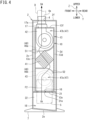
- FIG. 3 is a front view schematically illustrating the inside of the ventilation device.
- FIG. 4 is a sectional view taken along line A-A in FIG. 3 .
- FIG. 5 is a sectional view taken along line B-B in FIG. 3 .
- the tubular bodies 14a and 17a mounted to the top plate 13f of the auxiliary casing 13 have distal ends respectively communicating with the main return air intake port 3 and main air supply port 4 in the main casing 2. Since the electric component unit 27 is mounted to the right side plate 13a of the auxiliary casing 13, a spacing T between the right side plate 13a and the right side plate 2a of the main casing 2 is wider than spacings between the other side plates of the auxiliary casing 13 and the corresponding side plates of the main casing 2. This spacing T may alternatively be secured between one of the other side plates of the auxiliary casing 13 and the corresponding one of the other side plates of the main casing 2.
- a waterproof panel 21 is mounted to a lower surface of the bottom plate 13e of the auxiliary casing 13.
- the waterproof panel 21 is formed of, for example, a metal plate member covered with a waterproof coating or subjected to surface treatment for waterproofness, to impart waterproofness to the lower surface of the bottom plate 13e.
- the waterproof panel 21 covers the entire lower surface of the bottom plate 13e.
- the waterproof panel 21 has an opening 21a communicating with the auxiliary outside air intake port 16 and an opening 21b communicating with the auxiliary exhaust port 15.
- the waterproof panel 21 includes an extended portion 21c extending from the bottom plate 13e to the right side plate 2a of the main casing 2.
- the extended portion 21c is located in the spacing T.
- the extended portion 21c extends upward beyond the bottom plate 13e and reaches the right side plate 2a at a position higher than the bottom plate 13e.
- the waterproof panel 21 has a length in the front-and-rear direction substantially equal to a distance between the front side plate 2c and the rear side plate 2d of the main casing 2 in the front-and-rear direction.
- the waterproof panel 21 has a length in the left-and-right direction substantially equal to a distance between the right side plate 2a and the left side plate 2b of the main casing 2 in the left-and-right direction.
- the waterproof panel 21 separates the space defined by the right side plate 2a, the left side plate 2b, the front side plate 2c, and the rear side plate 2d into two in the up-and-down direction, and suppresses intrusion of water from the space below the waterproof panel 21 into the space above the waterproof panel 21.
- the waterproof panel 21 may be constituted of a single member or may be constituted of a combination of multiple members.
- the main casing 2 has an outside air intake chamber 18 and an exhaust chamber 19 each defined between the bottom plate (the partition) 13e of the auxiliary casing 13 and the bottom plate 2e of the main casing 2.
- the outside air intake chamber 18 communicates with the main outside air intake port 5 and the auxiliary outside air intake port 16.
- the exhaust chamber 19 communicates with the main exhaust port 6 and the auxiliary exhaust port 15.
- the waterproof panel 21 defines an upper end of the outside air intake chamber 18. Therefore, the waterproof panel 21 also serves as a partition in this respect.
- the outside air intake chamber 18 and the exhaust chamber 19 are defined by a divider 22 in the left-and-right direction.
- the divider 22 is placed with a slight clearance between the divider 22 and bottom plate 2e of the main casing 2. This clearance permits flow of water on the bottom plate 2e from the outside air intake chamber 18 to the exhaust chamber 19 and vice versa.
- the main return air intake port 3 in the main casing 2 is used for taking air in the building (i.e., return air RA from the building) in the main casing 2.
- the auxiliary return air intake port 14 in the auxiliary casing 13 is used for taking the return air RA from the building in the auxiliary casing 13.
- the main exhaust port 6, exhaust chamber 19, and auxiliary exhaust port 15 are used for discharging the return air RA in the main casing 2 and auxiliary casing 13 outdoors as exhaust air EA.
- the main outside air intake port 5, outside air intake chamber 18, and auxiliary outside air intake port 16 are used for taking air outside the building (i.e., outside air OA) in the main casing 2 and auxiliary casing 13.
- the main air supply port 4 and auxiliary air supply port 17 are used for supplying the outside air OA in the main casing 2 and auxiliary casing 13, indoors as supply air SA.
- the main outside air intake port 5 extends upward beyond the partition 13e, from a range below the partition 13e in the right side plate 2a.
- the waterproof panel 21 extends from the lower surface of the partition 13e to a position above an upper end of the main outside air intake port 5.
- the main exhaust port 6 is defined in a range below the partition 13e in the left side plate 2b. Therefore, the main exhaust port 6 is smaller in area than the main outside air intake port 5.
- the main exhaust port 6 may extend upward beyond the partition 13e, from the range below the partition 13e, as in the main outside air intake port 5.
- the main outside air intake port 5 may be defined only in the range below the partition 13e.
- the main outside air intake port 5 is covered with a protective net 24, and the main exhaust port 6 may be covered with a protective net 26.
- the main outside air intake port 5 is further covered with a filter 25.
- the bottom plate 2e of the main casing 2 has a drain port 2g.
- the drain port 2g is located in the exhaust chamber 19.
- the bottom plate 2e is tilted such that the drain port 2g becomes lowest in position. As a result, water on the bottom plate 2e flows toward the drain port 2g and then flows out of the main casing 2 through the drain port 2g.
- the total heat exchanger 41, the air supply fan 42, and the exhaust fan 43 are placed in the auxiliary casing 13.
- return air RA taken in the main casing 2 and auxiliary casing 13 through the main return air intake port 3 and auxiliary return air intake port 14 flows through the total heat exchanger 41 and then flows out of the auxiliary casing 13 through the auxiliary exhaust port 15, exhaust chamber 19, and main exhaust port 6, as exhaust air EA.
- this flow of air is also referred to as "a first air flow Fl".
- this flow of air is also referred to as "a second air flow F2".
- FIG. 7 is a perspective view of the total heat exchanger.
- the total heat exchanger 41 is an orthogonal total heat exchanger through which the first air flow F1 and the second air flow F2 pass substantially orthogonally.
- the total heat exchanger 41 includes dividers 41a and spacing plates 41b.
- the dividers 41a and the spacing plates 41b are stacked alternately and bonded together with an appropriate adhesive.
- the total heat exchanger 41 has a substantially quadrangular prism shape as a whole.
- the dividers 41a each possess heat conductivity and moisture permeability and have a flat plate shape.
- the dividers 41a each possess a property that allows transmission of a refrigerant.
- the spacing plates 41b each have a corrugated shape made up of consecutive substantially triangular sections. Each spacing plate 41b forms an air passage between adjacent two of the dividers 41a.
- the spacing plates 41b are stacked with their angles changed 90 degrees one by one in the direction along which the dividers 41a and spacing plates 41b are stacked.
- an exhaust air-side passage 41c through which the first air flow F 1 passes and a supply air-side passage 41d through which the second air flow F2 passes are defined orthogonally with one divider 41a sandwiched therebetween.
- Each divider 41a possessing heat conductivity and moisture permeability performs exchange between sensible heat and latent heat (i.e., total heat exchange) on air flowing through the exhaust air-side passage 41c and air flowing through the supply air-side passage 41d.
- the total heat exchanger 41 divides the inside of the auxiliary casing 13 into an indoor-side region (an upper side in the auxiliary casing 13) and an outdoor-side region (a lower side in the auxiliary casing 13).
- an upstream-side exhaust air path 46a is formed upstream of the total heat exchanger 41 in the first air flow F1
- a downstream-side exhaust air path 46b is formed downstream of the total heat exchanger 41 in the first air flow F1.
- the upstream-side exhaust air path 46a and the downstream-side exhaust air path 46b form an exhaust air path 46 that causes the inside of the building and the outside of the building to communicate with each other via the total heat exchanger 41.
- an upstream-side supply air path 47a is formed upstream of the total heat exchanger 41 in the second air flow F2 and a downstream-side supply air path 47b is formed downstream of the total heat exchanger 41 in the second air flow F2.
- the upstream-side supply air path 47a and the downstream-side supply air path 47b form a supply air path 47 that causes the inside of the building and the outside of the building to communicate with each other via the total heat exchanger 41.
- a partition wall 51 is disposed between the upstream-side exhaust air path 46a and the downstream-side supply air path 47b.
- a partition wall 52 is disposed between the downstream-side exhaust air path 46b and the upstream-side supply air path 47a.
- the exhaust fan 43 is placed near the auxiliary exhaust port 15 on the downstream-side exhaust air path 46b.
- the exhaust fan 43 when being driven, generates the first air flow F1, so that return air RA from the building flows through the exhaust air path 46 and then flows outdoors as exhaust air EA.
- the air supply fan 42 is placed near the auxiliary air supply port 17 on the downstream-side supply air path 47b.
- the air supply fan 42 when being driven, generates the second air flow F2, so that outside air OA outside the building flows through the supply air path 47 and then flows indoors as supply air SA.
- a ventilating operation is carried out when the exhaust fan 43 and the air supply fan 42 are driven. Ventilation of air in the building is thus provided in such a manner that return air RA from the building is discharged from the building while outside air OA outside the building is supplied into the building. In addition, variations in temperature and humidity in the building are suppressed in such a manner that the total heat exchanger 41 performs exchange between sensible heat and latent heat on the return air RA from the building and the outside air OA outside the building.
- the total heat exchanger 41 is extractable sideward (i.e., in a direction indicated by a white arrow) from the auxiliary casing 13.
- the total heat exchanger 41 according to this embodiment includes a portion 41e protruding from the right side plate 13a, and this portion 41e is provided with a handle 41f. A worker grips the handle 41f and pulls the total heat exchanger 41 in the direction indicated by the white arrow, thereby extracting the total heat exchanger 41 from the auxiliary casing 13.
- reference sign K denotes a projection region of the total heat exchanger 41 extracted sideward, that is, a spatial region where the total heat exchanger 41 passes when the total heat exchanger 41 is extracted from the auxiliary casing 13.
- FIG. 8 is a perspective view illustrating the ventilation device from which a side plate is detached.
- the right side surface of the main casing 2 is opened when the right side plate 2a is detached from the main casing 2. Therefore, the total heat exchanger 41 can be extracted sideward from the auxiliary casing 13 and main casing 2 through this opening. Since the total heat exchanger 41 is extractable from the auxiliary casing 13 and the main casing 2, the total heat exchanger 41 can be maintained or replaced with a new one with ease.
- the electric component unit 27 is exposed to the outside. Therefore, the electric component unit 27 can be operated or maintained with ease.
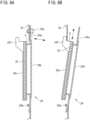
- FIGs. 6A and 6B are sectional views of the main outside air intake port and its surroundings.
- the protective net 24 includes a frame member 24a having a quadrilateral shape and a net member 24b attached to the frame member 24a.
- the protective net 24 is provided with the filter 25.
- the frame member 24a of the protective net 24 has guide grooves 24c into which front and rear end edges of the filter 25 can be inserted in the up-and-down direction.
- the frame member 24a has a lower end mounted to the main casing 2 so as to be swingable on a pivot 24d in the left-and-right direction.
- the frame member 24a has an upper end fixed to the right side plate 2a with a fixing member 24e.
- the fixing of the frame member 24a with the fixing member 24e is released, and the frame member 24a is swung rightward, so that upper ends of the guide grooves 24c are exposed to the outside of the main casing 2.
- the swinging motion of the frame member 24a is restricted with a stopper 24f of the frame member 24a abutting against the right side plate 2a.
- the filter 25 can be attached to and detached from the guide grooves 24c in this state.
- the ventilation device 1 may include, instead of the total heat exchanger 41, another heat exchanger such as a heat exchanger through which a heat exchange medium (e.g., a refrigerant) flows.
- a heat exchange medium e.g., a refrigerant
- the ventilation device 1 does not necessarily include a heat exchanger.
- the ventilation device 1 may include a filter rather than a heat exchanger.
- the main outside air intake port 5 may be bored in one of the left side plate 2b, front side plate 2c, and rear side plate 2d of the main casing 2.
- the main exhaust port 6 may be bored in one of the right side plate 2a, front side plate 2c, and rear side plate 2d of the main casing 2.
- the positional relationship between the main outside air intake port 5 and the main exhaust port 6 is not limited unless outside air and exhaust air are mixed together.
- the ventilation device 1 does not necessarily include the auxiliary casing 13.
- the accommodation space S, the outside air intake chamber 18, the exhaust chamber 19, and the like may be defined in such a manner that the inside of the main casing 2 is divided by a partition.
- the outside air intake chamber 18 and the exhaust chamber 19 are defined between the bottom plate 2e of the casing 2 and the partition 13e above the bottom plate 2e. Therefore, even when water intrudes into the casing 2 through the main outside air intake port 5 and main exhaust port 6 each bored in the casing 2, the water can be retained in the outside air intake chamber 18 and exhaust chamber 19.
- the ventilation device 1 is thus capable of suppressing intrusion of the water into the accommodation space S above the partition 13e.
- the ventilation device 1 is therefore capable of suppressing adverse influence to be exerted on electric components (e.g., the air supply fan 42, the exhaust fan 43) and electric wires in the accommodation space S.
- the bottom plate 2e of the casing 2 has the drain port 2g located in the exhaust chamber 19.
- the ventilation device 1 is therefore capable of suppressing freezing of water intruding into the exhaust chamber 19 to suppress clogging of the drain port 2g with ice.
- the bottom plate 2e of the casing 2 is tilted such that the drain port 2g is lower in position. According to this configuration, water, when intruding into the outside air intake chamber 18 and exhaust chamber 19, flows toward the drain port 2g in the exhaust chamber 19.
- the ventilation device 1 is therefore capable of draining the water through the drain port 2g without a disadvantageous situation in which the water is frozen.
- the partition 13e has the lower surface to which waterproofness is imparted. Therefore, the partition 13e is less susceptible to deterioration (e.g., rusting) owing to water intruding into the outside air intake chamber 18 and exhaust chamber 19.
- deterioration e.g., rusting
- the ventilation device 1 further includes the waterproof panel 21 having waterproofness, the waterproof panel 21 disposed on the lower surface of the partition 13e. Therefore, waterproofness can be imparted to the lower surface of the partition 13e with ease.
- a ventilation device designed to be installed indoors is used as the ventilation device main body 10.
- the auxiliary casing 13 does not possess such waterproofness as to withstand outdoor installation.
- the waterproof panel 21 is mounted to the lower surface of the bottom plate 13e (serving as the partition 13e) of the auxiliary casing 13, so that waterproofness can be imparted to the bottom plate 13e with ease.
- the main outside air intake port 5 or the main exhaust port 6 extends upward beyond the partition 13e, from the range below the partition 13e in the corresponding one of the side plates 2a, 2b, 2c, 2d.
- the ventilation device 1 is therefore capable of increasing an amount of supply air through the main outside air intake port 5 extended in the up-and-down direction or an amount of exhaust air through the main exhaust port 6 extended in the up-and-down direction.
- the casing 2 includes the first side plate 2a, 2b, 2c, 2d having the main outside air intake port 5 or the main exhaust port 6, the first side plate 2a, 2b, 2c, 2d spaced horizontally away from the partition 13e (the right side plate 2a having the main outside air intake port 5 in the example illustrated in FIG. 3 ).
- the main outside air intake port 5 or main exhaust port 6 in the first side plate 2a, 2b, 2c, 2d extends upward beyond the partition 13e, from the range below the partition 13e in the first side plate 2a, 2b, 2c, 2d.
- the waterproof panel 21 extends from the lower surface of the partition 13e to the position above the main outside air intake port 5 in the first side plate 2a, 2b, 2c, 2d. Therefore, the outside air intake chamber 18 can be defined between the partition 13e and the first side plate 2a, 2b, 2c, 2d, with the waterproof panel 21.
- the waterproof panel 21 is capable of suppressing adhesion, to the auxiliary casing 13, water intruding into the outside air intake chamber 18 through the outside air intake port 5.
- the casing 2, 13 includes the auxiliary casing 13 in which the air supply fan 42 and the exhaust fan 43 are accommodated, and the main casing 2 in which the auxiliary casing 13 is accommodated.
- the partition 13e serves as the bottom plate of the auxiliary casing 13.
- the outside air intake chamber 18 and the exhaust chamber 19 are defined between the bottom plate 13e of the auxiliary casing 13 and the bottom plate 2e of the main casing 2. Therefore, in a case where a known ventilation device designed to be installed indoors is used as the ventilation device main body 10, the outside air intake chamber 18 and the exhaust chamber 19 can be defined in the main casing 2.
Landscapes
- Engineering & Computer Science (AREA)
- Chemical & Material Sciences (AREA)
- Combustion & Propulsion (AREA)
- Mechanical Engineering (AREA)
- General Engineering & Computer Science (AREA)
- Physics & Mathematics (AREA)
- Thermal Sciences (AREA)
- Cooling Or The Like Of Electrical Apparatus (AREA)
- Ventilation (AREA)
- Seal Device For Vehicle (AREA)
- Liquid Crystal (AREA)
Abstract
Description
- The present disclosure relates to a ventilation device.
-
Patent Literature 1 discloses a ventilation device to be installed outdoors. This ventilation device includes an exhaust fan, an air supply fan, a heat exchanger, and a casing accommodating these components. The casing has a lower stage portion where the exhaust fan is placed, an upper stage portion where the air supply fan is placed, and a middle stage portion where the heat exchanger is placed. The casing has an exhaust air port bored in its front surface and located at the lower stage portion, a return air opening and a supply air opening each bored in its rear surface and located at the upper stage portion, and outside air ports respectively bored in its left and right side surfaces and located at the middle stage portion. - According to the ventilation device disclosed in
Patent Literature 1, when the air supply fan operates, outdoor air flows into the casing through the outside air port, and then flows through the heat exchanger. The air is then guided indoors through the supply air opening. When the exhaust fan operates, indoor air flows into the casing through the return air opening, and then flows through the heat exchanger. The air is then discharged outdoors through the exhaust air port. - PATENT LITERATURE 1:
Japanese Laid-Open Patent Publication No. 2014-20768 - In the ventilation device disclosed in
Patent Literature 1, the exhaust air port is bored in the front surface of the casing and is located at the lower stage portion in the casing. The exhaust air port is therefore located near the ground. Consequently, rainwater and the like possibly intrude into the casing through the exhaust air port. At the lower stage portion in the casing, the exhaust fan, an electric wire connected to the exhaust fan, and the like are possibly affected by water intruding into the casing. - An object of the present disclosure is to suppress intrusion of water into a space where a fan is accommodated, in a ventilation device to be installed outdoors.
-
- (1) The present disclosure provides a ventilation device to be installed outdoors,
the ventilation device including:- an air supply fan;
- an exhaust fan; and
- a casing having an accommodation space in which the air supply fan and the exhaust fan are accommodated,
- wherein
- the casing includes a partition defining a lower end of the accommodation space,
- the partition has a first outside air intake port and a first exhaust port each passing through the partition in an up-and-down direction,
- the casing includes a bottom plate and has an outside air intake chamber defined between the bottom plate and the partition located above the bottom plate, the outside air intake chamber communicating with the first outside air intake port, and an exhaust chamber defined between the bottom plate and the partition located above the bottom plate, the exhaust chamber communicating with the first exhaust port, and
- the casing includes side plates respectively having a second outside air intake port through which the outside air intake chamber communicates with an outside of the casing and a second exhaust port through which the exhaust chamber communicates with the outside of the casing.
- In the ventilation device having this configuration, the outside air intake chamber and the exhaust chamber are defined between the bottom plate of the casing and the partition above the bottom plate. Therefore, even when water intrudes into the casing through the second outside air intake port and second exhaust port each bored in the casing, the water can be retained in the outside air intake chamber and exhaust chamber. The ventilation device is thus capable of suppressing intrusion of the water into the accommodation space above the partition.
- (2) Preferably, the bottom plate of the casing has a drain port located in the exhaust chamber.
- According to this configuration, during use of the ventilation device in the wintertime, relatively warm air in a building flows into the exhaust chamber through the first exhaust port. The ventilation device is therefore capable of suppressing freezing of water intruding into the exhaust chamber to suppress clogging of the drain port with ice.
- (3) Preferably, the bottom plate of the casing is tilted such that the drain port is lower in position.
- According to this configuration, water, when intruding into the outside air intake chamber and exhaust chamber, flows toward the drain port in the exhaust chamber. The ventilation device is therefore capable of draining the water without a disadvantageous situation in which the water is frozen.
- (4) Preferably, the partition has a lower surface to which waterproofness is imparted.
- According to this configuration, the partition is less susceptible to deterioration (e.g., rusting) owing to water intruding into the outside air intake chamber and exhaust chamber.
- (5) Preferably, the ventilation device further includes a waterproof panel having waterproofness, the waterproof panel disposed on the lower surface of the partition.
- According to this configuration, waterproofness can be imparted to the lower surface of the partition with ease.
- (6) Preferably, the second outside air intake port or the second exhaust port extends upward beyond the partition, from a range below the partition in the corresponding one of the side plates.
- According to this configuration, the second outside air intake port or the second exhaust port extends within the range below the partition in the corresponding one of the side plates, and further extends upward beyond the partition. The ventilation device is therefore capable of easily increasing an amount of supply air through the second outside air intake port extended in the up-and-down direction or an amount of exhaust air through the second exhaust port extended in the up-and-down direction.
- (7) Preferably, the casing includes a first side plate having the second outside air intake port or the second exhaust port, the first side plate spaced horizontally away from the partition,
- the second outside air intake port or second exhaust port in the first side plate extends upward beyond the partition, from a range below the partition in the first side plate, and
- the waterproof panel extends from the lower surface of the partition to a position above the second outside air intake port or second exhaust port in the first side plate.
- According to this configuration, the outside air intake chamber or the exhaust chamber can be defined between the partition and the first side plate, with the waterproof panel.
- (8) Preferably, the casing includes: a second casing in which the air supply fan and the exhaust fan are accommodated; and a first casing in which the second casing is accommodated,
- the partition serves as a bottom plate of the second casing, and
- the outside air intake chamber and the exhaust chamber are defined between the bottom plate of the second casing and a bottom plate of the first casing.
-
-
FIG. 1 is a perspective view of a ventilation device according to an embodiment of the present disclosure. -
FIG. 2 is a perspective view of a ventilation device main body. -
FIG. 3 is a front view schematically illustrating the inside of the ventilation device. -
FIG. 4 is a sectional view taken along line A-A inFIG. 3 . -
FIG. 5 is a sectional view taken along line B-B inFIG. 3 . -
FIGs. 6A and 6B are sectional views of a main outside air intake port and its surroundings. -
FIG. 7 is a perspective view of a total heat exchanger. -
FIG. 8 is a perspective view illustrating the ventilation device from which a side plate is detached. - Hereinafter, embodiments of the present disclosure will be described in detail with reference to the accompanying drawings.
-
FIG. 1 is a perspective view of a ventilation device according to an embodiment of the present disclosure. - In the following description, the terms "upper", "lower", "front", "rear", "left", and "right" are indicated by arrows illustrated in
FIGs. 1 to 3 in conjunction with these terms. Particularly inFIG. 1 , a first direction indicated by an arrow X is defined as a left-and-right direction, a second direction indicated by an arrow Y is defined as a front-and-rear direction, and a third direction indicated by an arrow Z is defined as an up-and-down direction. However, these definitions are merely exemplary. For example, the first direction X may be regarded as the front-and-rear direction and the second direction Y may be regarded as the left-and-right direction. - The
ventilation device 1 is configured to exchange air in a building (i.e., air in a room) with air outside the building (i.e., air outside the room), thereby providing ventilation of air in the building. Theventilation device 1 is installed outside the building. Theventilation device 1 is connected to the inside of the building with two ducts D. Theventilation device 1 includes a main casing (a first casing) 2 having a rectangular parallelepiped box shape. Theventilation device 1 according to this embodiment includes an auxiliary casing 13 (to be described later) in addition to themain casing 2. - The
main casing 2 includes abottom plate 2e, atop plate 2f, aright side plate 2a, aleft side plate 2b, afront side plate 2c, and arear side plate 2d. Thebottom plate 2e and thetop plate 2f each have a rectangular shape in plan view and are opposite to each other with a spacing in between in the up-and-down direction. Theright side plate 2a, theleft side plate 2b, thefront side plate 2c, and therear side plate 2d connect the four sides of thebottom plate 2e and the four sides of thetop plate 2f, respectively. - The
top plate 2f of themain casing 2 has a main return air intake port (a second return air intake port) 3 and a main air supply port (a second air supply port) 4. Atubular body 3a and atubular body 4a are respectively mounted to the main returnair intake port 3 and the mainair supply port 4. Thetubular bodies air intake port 3 and the mainair supply port 4 communicate with the inside of the building via the ducts D. - The
bottom plate 2e of themain casing 2 is provided with a pair oflegs 7. Theventilation device 1 is installed outside the building in such a manner that theventilation device 1 is fastened using bolts or the like with thelegs 7 mounted on the ground. Theventilation device 1 is not necessarily placed on the ground. For example, theventilation device 1 may be placed on a pedestal mounted to, for example, an outer wall of the building or the roof of the building. - The
right side plate 2a of themain casing 2 has a main outside air intake port (a second outside air intake port) 5. Theleft side plate 2b of themain casing 2 has a main exhaust port (a second exhaust port) 6. - The
main casing 2 accommodates a ventilation devicemain body 10. The ventilation devicemain body 10 according to this embodiment is a known ventilation device designed to be installed in an attic or hung on a wall surface in a building. Theventilation device 1 according to the present disclosure is designed to be installed outdoors in such a manner that a ventilation device designed to be installed indoors is accommodated in themain casing 2. Ventilation devices designed to be installed indoors are not exposed to rain unlike ventilation devices designed to be installed outdoors; therefore, due consideration concerning waterproofness is not given to the ventilation devices designed to be installed indoors. In view of this, theventilation device 1 according to the present disclosure is installable outdoors in such a manner that a ventilation device designed to be installed indoors is accommodated in themain casing 2 excellent in waterproofness. As a matter of course, theventilation device 1 according to the present disclosure may employ a ventilation device designed to be installed only outdoors, rather than the ventilation device designed to be installed indoors. -
FIG. 2 is a perspective view of the ventilation device main body. - The ventilation device
main body 10 includes an auxiliary casing (a second casing) 13 having a rectangular parallelepiped box shape. Theauxiliary casing 13 substantially has an accommodation space S for accommodating anair supply fan 42, anexhaust fan 43, and atotal heat exchanger 41, which will be described later (seeFIG. 3 ). Theauxiliary casing 13 includes abottom plate 13e, atop plate 13f, aright side plate 13a, aleft side plate 13b, afront side plate 13c, and arear side plate 13d. Thebottom plate 13e and thetop plate 13f each have a rectangular shape in plan view and are opposite to each other with a spacing in between in the up-and-down direction. Theright side plate 13a, theleft side plate 13b, thefront side plate 13c, and therear side plate 13d connect the four sides of thebottom plate 13e and the four sides of thetop plate 13f, respectively. - An
electric component unit 27 is mounted to an upper portion of theright side plate 13a. Theelectric component unit 27 includes abox 27a and electric components, such as a control board and a terminal block, accommodated in thebox 27a. Theelectric component unit 27 may alternatively be mounted to one of theother side plates - The
top plate 13f of theauxiliary casing 13 has an auxiliary return air intake port (a first return air intake port) 14 and an auxiliary air supply port (a first air supply port) 17. Atubular body 14a and atubular body 17a are respectively mounted to the auxiliary returnair intake port 14 and the auxiliaryair supply port 17. - The
bottom plate 13e of theauxiliary casing 13 serves as a partition defining a lower end of the accommodation space S for accommodating theair supply fan 42, theexhaust fan 43, and thetotal heat exchanger 41. Thebottom plate 13e of theauxiliary casing 13 has an auxiliary outside air intake port (a first outside air intake port) 16 and an auxiliary exhaust port (a first exhaust port) 15. Atubular body 15a is mounted to theauxiliary exhaust port 15. However, thetubular body 15a is not necessarily mounted to theauxiliary exhaust port 15. -
FIG. 3 is a front view schematically illustrating the inside of the ventilation device.FIG. 4 is a sectional view taken along line A-A inFIG. 3 .FIG. 5 is a sectional view taken along line B-B inFIG. 3 . - The
tubular bodies top plate 13f of theauxiliary casing 13 have distal ends respectively communicating with the main returnair intake port 3 and mainair supply port 4 in themain casing 2. Since theelectric component unit 27 is mounted to theright side plate 13a of theauxiliary casing 13, a spacing T between theright side plate 13a and theright side plate 2a of themain casing 2 is wider than spacings between the other side plates of theauxiliary casing 13 and the corresponding side plates of themain casing 2. This spacing T may alternatively be secured between one of the other side plates of theauxiliary casing 13 and the corresponding one of the other side plates of themain casing 2. - A
waterproof panel 21 is mounted to a lower surface of thebottom plate 13e of theauxiliary casing 13. Thewaterproof panel 21 is formed of, for example, a metal plate member covered with a waterproof coating or subjected to surface treatment for waterproofness, to impart waterproofness to the lower surface of thebottom plate 13e. Thewaterproof panel 21 covers the entire lower surface of thebottom plate 13e. Thewaterproof panel 21 has anopening 21a communicating with the auxiliary outsideair intake port 16 and anopening 21b communicating with theauxiliary exhaust port 15. Thewaterproof panel 21 includes anextended portion 21c extending from thebottom plate 13e to theright side plate 2a of themain casing 2. Theextended portion 21c is located in the spacing T. Theextended portion 21c extends upward beyond thebottom plate 13e and reaches theright side plate 2a at a position higher than thebottom plate 13e. - The
waterproof panel 21 has a length in the front-and-rear direction substantially equal to a distance between thefront side plate 2c and therear side plate 2d of themain casing 2 in the front-and-rear direction. Thewaterproof panel 21 has a length in the left-and-right direction substantially equal to a distance between theright side plate 2a and theleft side plate 2b of themain casing 2 in the left-and-right direction. Thewaterproof panel 21 separates the space defined by theright side plate 2a, theleft side plate 2b, thefront side plate 2c, and therear side plate 2d into two in the up-and-down direction, and suppresses intrusion of water from the space below thewaterproof panel 21 into the space above thewaterproof panel 21. Thewaterproof panel 21 may be constituted of a single member or may be constituted of a combination of multiple members. - The
main casing 2 has an outsideair intake chamber 18 and anexhaust chamber 19 each defined between the bottom plate (the partition) 13e of theauxiliary casing 13 and thebottom plate 2e of themain casing 2. The outsideair intake chamber 18 communicates with the main outsideair intake port 5 and the auxiliary outsideair intake port 16. Theexhaust chamber 19 communicates with themain exhaust port 6 and theauxiliary exhaust port 15. Thewaterproof panel 21 defines an upper end of the outsideair intake chamber 18. Therefore, thewaterproof panel 21 also serves as a partition in this respect. - The outside
air intake chamber 18 and theexhaust chamber 19 are defined by adivider 22 in the left-and-right direction. Thedivider 22 is placed with a slight clearance between thedivider 22 andbottom plate 2e of themain casing 2. This clearance permits flow of water on thebottom plate 2e from the outsideair intake chamber 18 to theexhaust chamber 19 and vice versa. - The main return
air intake port 3 in themain casing 2 is used for taking air in the building (i.e., return air RA from the building) in themain casing 2. The auxiliary returnair intake port 14 in theauxiliary casing 13 is used for taking the return air RA from the building in theauxiliary casing 13. Themain exhaust port 6,exhaust chamber 19, andauxiliary exhaust port 15 are used for discharging the return air RA in themain casing 2 andauxiliary casing 13 outdoors as exhaust air EA. The main outsideair intake port 5, outsideair intake chamber 18, and auxiliary outsideair intake port 16 are used for taking air outside the building (i.e., outside air OA) in themain casing 2 andauxiliary casing 13. The mainair supply port 4 and auxiliaryair supply port 17 are used for supplying the outside air OA in themain casing 2 andauxiliary casing 13, indoors as supply air SA. - The main outside
air intake port 5 extends upward beyond thepartition 13e, from a range below thepartition 13e in theright side plate 2a. Thewaterproof panel 21 extends from the lower surface of thepartition 13e to a position above an upper end of the main outsideair intake port 5. On the other hand, themain exhaust port 6 is defined in a range below thepartition 13e in theleft side plate 2b. Therefore, themain exhaust port 6 is smaller in area than the main outsideair intake port 5. It should be noted that themain exhaust port 6 may extend upward beyond thepartition 13e, from the range below thepartition 13e, as in the main outsideair intake port 5. Conversely, the main outsideair intake port 5 may be defined only in the range below thepartition 13e. As illustrated inFIGs. 1 and3 , the main outsideair intake port 5 is covered with aprotective net 24, and themain exhaust port 6 may be covered with aprotective net 26. The main outsideair intake port 5 is further covered with afilter 25. - The
bottom plate 2e of themain casing 2 has adrain port 2g. Thedrain port 2g is located in theexhaust chamber 19. Thebottom plate 2e is tilted such that thedrain port 2g becomes lowest in position. As a result, water on thebottom plate 2e flows toward thedrain port 2g and then flows out of themain casing 2 through thedrain port 2g. - The
total heat exchanger 41, theair supply fan 42, and theexhaust fan 43 are placed in theauxiliary casing 13. In themain casing 2 andauxiliary casing 13, return air RA taken in themain casing 2 andauxiliary casing 13 through the main returnair intake port 3 and auxiliary returnair intake port 14 flows through thetotal heat exchanger 41 and then flows out of theauxiliary casing 13 through theauxiliary exhaust port 15,exhaust chamber 19, andmain exhaust port 6, as exhaust air EA. Hereinafter, this flow of air is also referred to as "a first air flow Fl". Outside air OA taken in themain casing 2 andauxiliary casing 13 through the main outsideair intake port 5, outsideair intake chamber 18, and auxiliary outsideair intake port 16 flows through thetotal heat exchanger 41 and then flows into the building through the auxiliaryair supply port 17 and mainair supply port 4, as supply air SA. Hereinafter, this flow of air is also referred to as "a second air flow F2". -
FIG. 7 is a perspective view of the total heat exchanger. - The
total heat exchanger 41 according to this embodiment is an orthogonal total heat exchanger through which the first air flow F1 and the second air flow F2 pass substantially orthogonally. Thetotal heat exchanger 41 includesdividers 41a andspacing plates 41b. Thedividers 41a and thespacing plates 41b are stacked alternately and bonded together with an appropriate adhesive. Thetotal heat exchanger 41 has a substantially quadrangular prism shape as a whole. - The
dividers 41a each possess heat conductivity and moisture permeability and have a flat plate shape. Thedividers 41a each possess a property that allows transmission of a refrigerant. - The
spacing plates 41b each have a corrugated shape made up of consecutive substantially triangular sections. Eachspacing plate 41b forms an air passage between adjacent two of thedividers 41a. Thespacing plates 41b are stacked with their angles changed 90 degrees one by one in the direction along which thedividers 41a andspacing plates 41b are stacked. As a result, an exhaust air-side passage 41c through which the firstair flow F 1 passes and a supply air-side passage 41d through which the second air flow F2 passes are defined orthogonally with onedivider 41a sandwiched therebetween. Eachdivider 41a possessing heat conductivity and moisture permeability performs exchange between sensible heat and latent heat (i.e., total heat exchange) on air flowing through the exhaust air-side passage 41c and air flowing through the supply air-side passage 41d. - As illustrated in
FIGs. 3 to 5 , thetotal heat exchanger 41 divides the inside of theauxiliary casing 13 into an indoor-side region (an upper side in the auxiliary casing 13) and an outdoor-side region (a lower side in the auxiliary casing 13). As illustrated inFIGs. 3 and5 , in theauxiliary casing 13, an upstream-sideexhaust air path 46a is formed upstream of thetotal heat exchanger 41 in the first air flow F1, and a downstream-sideexhaust air path 46b is formed downstream of thetotal heat exchanger 41 in the first air flow F1. The upstream-sideexhaust air path 46a and the downstream-sideexhaust air path 46b form anexhaust air path 46 that causes the inside of the building and the outside of the building to communicate with each other via thetotal heat exchanger 41. - As illustrated in
FIGs. 3 and4 , in theauxiliary casing 13, an upstream-sidesupply air path 47a is formed upstream of thetotal heat exchanger 41 in the second air flow F2, and a downstream-sidesupply air path 47b is formed downstream of thetotal heat exchanger 41 in the second air flow F2. The upstream-sidesupply air path 47a and the downstream-sidesupply air path 47b form asupply air path 47 that causes the inside of the building and the outside of the building to communicate with each other via thetotal heat exchanger 41. - As illustrated in
FIG. 3 , apartition wall 51 is disposed between the upstream-sideexhaust air path 46a and the downstream-sidesupply air path 47b. Apartition wall 52 is disposed between the downstream-sideexhaust air path 46b and the upstream-sidesupply air path 47a. - As illustrated in
FIGs. 3 and5 , theexhaust fan 43 is placed near theauxiliary exhaust port 15 on the downstream-sideexhaust air path 46b. Theexhaust fan 43, when being driven, generates the first air flow F1, so that return air RA from the building flows through theexhaust air path 46 and then flows outdoors as exhaust air EA. - As illustrated in
FIGs. 3 and4 , theair supply fan 42 is placed near the auxiliaryair supply port 17 on the downstream-sidesupply air path 47b. Theair supply fan 42, when being driven, generates the second air flow F2, so that outside air OA outside the building flows through thesupply air path 47 and then flows indoors as supply air SA. - A ventilating operation is carried out when the
exhaust fan 43 and theair supply fan 42 are driven. Ventilation of air in the building is thus provided in such a manner that return air RA from the building is discharged from the building while outside air OA outside the building is supplied into the building. In addition, variations in temperature and humidity in the building are suppressed in such a manner that thetotal heat exchanger 41 performs exchange between sensible heat and latent heat on the return air RA from the building and the outside air OA outside the building. - As illustrated in
FIG. 2 , thetotal heat exchanger 41 is extractable sideward (i.e., in a direction indicated by a white arrow) from theauxiliary casing 13. Thetotal heat exchanger 41 according to this embodiment includes aportion 41e protruding from theright side plate 13a, and thisportion 41e is provided with ahandle 41f. A worker grips thehandle 41f and pulls thetotal heat exchanger 41 in the direction indicated by the white arrow, thereby extracting thetotal heat exchanger 41 from theauxiliary casing 13. InFIG. 2 , reference sign K denotes a projection region of thetotal heat exchanger 41 extracted sideward, that is, a spatial region where thetotal heat exchanger 41 passes when thetotal heat exchanger 41 is extracted from theauxiliary casing 13. -
FIG. 8 is a perspective view illustrating the ventilation device from which a side plate is detached. - In the
ventilation device 1 according to this embodiment, as illustrated inFIG. 8 , the right side surface of themain casing 2 is opened when theright side plate 2a is detached from themain casing 2. Therefore, thetotal heat exchanger 41 can be extracted sideward from theauxiliary casing 13 andmain casing 2 through this opening. Since thetotal heat exchanger 41 is extractable from theauxiliary casing 13 and themain casing 2, thetotal heat exchanger 41 can be maintained or replaced with a new one with ease. When theright side plate 2a of themain casing 2 is detached, theelectric component unit 27 is exposed to the outside. Therefore, theelectric component unit 27 can be operated or maintained with ease. -
FIGs. 6A and 6B are sectional views of the main outside air intake port and its surroundings. - As illustrated in
FIGs. 1 and6A , the main outsideair intake port 5 is covered with theprotective net 24. Theprotective net 24 includes aframe member 24a having a quadrilateral shape and anet member 24b attached to theframe member 24a. Theprotective net 24 is provided with thefilter 25. Theframe member 24a of theprotective net 24 hasguide grooves 24c into which front and rear end edges of thefilter 25 can be inserted in the up-and-down direction. - The
frame member 24a has a lower end mounted to themain casing 2 so as to be swingable on apivot 24d in the left-and-right direction. Theframe member 24a has an upper end fixed to theright side plate 2a with a fixingmember 24e. As illustrated inFIG. 6B , the fixing of theframe member 24a with the fixingmember 24e is released, and theframe member 24a is swung rightward, so that upper ends of theguide grooves 24c are exposed to the outside of themain casing 2. The swinging motion of theframe member 24a is restricted with astopper 24f of theframe member 24a abutting against theright side plate 2a. Thefilter 25 can be attached to and detached from theguide grooves 24c in this state. - The
ventilation device 1 may include, instead of thetotal heat exchanger 41, another heat exchanger such as a heat exchanger through which a heat exchange medium (e.g., a refrigerant) flows. - The
ventilation device 1 does not necessarily include a heat exchanger. For example, theventilation device 1 may include a filter rather than a heat exchanger. - The main outside
air intake port 5 may be bored in one of theleft side plate 2b,front side plate 2c, andrear side plate 2d of themain casing 2. Themain exhaust port 6 may be bored in one of theright side plate 2a,front side plate 2c, andrear side plate 2d of themain casing 2. The positional relationship between the main outsideair intake port 5 and themain exhaust port 6 is not limited unless outside air and exhaust air are mixed together. - The
ventilation device 1 does not necessarily include theauxiliary casing 13. For example, the accommodation space S, the outsideair intake chamber 18, theexhaust chamber 19, and the like may be defined in such a manner that the inside of themain casing 2 is divided by a partition. -
- (1) The
ventilation device 1 according to the foregoing embodiment is designed to be installed outdoors. Theventilation device 1 includes theair supply fan 42, theexhaust fan 43, and the casing (including themain casing 2 and the auxiliary casing 13) having the accommodation space S in which theair supply fan 42 and theexhaust fan 43 are accommodated. Thecasing 13 includes thepartition 13e defining the lower end of the accommodation space S. Thepartition 13e has the auxiliary outsideair intake port 16 and theauxiliary exhaust port 15 each passing through thepartition 13e in the up-and-down direction. Thecasing 2 includes thebottom plate 2e and has the outsideair intake chamber 18 defined between thebottom plate 2e and thepartition 13e located above thebottom plate 2e, the outsideair intake chamber 18 communicating with the auxiliary outsideair intake port 16, and theexhaust chamber 19 defined between thebottom plate 2e and thepartition 13e located above thebottom plate 2e, theexhaust chamber 19 communicating with theauxiliary exhaust port 15. Thecasing 2 includes theside plates air intake port 5 through which the outsideair intake chamber 18 communicates with the outside of thecasing 2 and themain exhaust port 6 through which theexhaust chamber 19 communicates with the outside of thecasing 2. - In the
ventilation device 1 designed to be installed outdoors and configured as described above, the outsideair intake chamber 18 and theexhaust chamber 19 are defined between thebottom plate 2e of thecasing 2 and thepartition 13e above thebottom plate 2e. Therefore, even when water intrudes into thecasing 2 through the main outsideair intake port 5 andmain exhaust port 6 each bored in thecasing 2, the water can be retained in the outsideair intake chamber 18 andexhaust chamber 19. Theventilation device 1 is thus capable of suppressing intrusion of the water into the accommodation space S above thepartition 13e. Theventilation device 1 is therefore capable of suppressing adverse influence to be exerted on electric components (e.g., theair supply fan 42, the exhaust fan 43) and electric wires in the accommodation space S. - (2) In the foregoing embodiment, the
bottom plate 2e of thecasing 2 has thedrain port 2g located in theexhaust chamber 19. During use of theventilation device 1 in the wintertime, relatively warm air in the building flows into theexhaust chamber 19 through theauxiliary exhaust port 15. Theventilation device 1 is therefore capable of suppressing freezing of water intruding into theexhaust chamber 19 to suppress clogging of thedrain port 2g with ice. - (3) In the foregoing embodiment, the
bottom plate 2e of thecasing 2 is tilted such that thedrain port 2g is lower in position. According to this configuration, water, when intruding into the outsideair intake chamber 18 andexhaust chamber 19, flows toward thedrain port 2g in theexhaust chamber 19. Theventilation device 1 is therefore capable of draining the water through thedrain port 2g without a disadvantageous situation in which the water is frozen. - (4) In the foregoing embodiment, the
partition 13e has the lower surface to which waterproofness is imparted. Therefore, thepartition 13e is less susceptible to deterioration (e.g., rusting) owing to water intruding into the outsideair intake chamber 18 andexhaust chamber 19. - (5) In the foregoing embodiment, the
ventilation device 1 further includes thewaterproof panel 21 having waterproofness, thewaterproof panel 21 disposed on the lower surface of thepartition 13e. Therefore, waterproofness can be imparted to the lower surface of thepartition 13e with ease. Particularly in the ventilation device according to the foregoing embodiment, a ventilation device designed to be installed indoors is used as the ventilation devicemain body 10. As a result, theauxiliary casing 13 does not possess such waterproofness as to withstand outdoor installation. In view of this, thewaterproof panel 21 is mounted to the lower surface of thebottom plate 13e (serving as thepartition 13e) of theauxiliary casing 13, so that waterproofness can be imparted to thebottom plate 13e with ease. - (6) In the foregoing embodiment, the main outside
air intake port 5 or themain exhaust port 6 extends upward beyond thepartition 13e, from the range below thepartition 13e in the corresponding one of theside plates ventilation device 1 is therefore capable of increasing an amount of supply air through the main outsideair intake port 5 extended in the up-and-down direction or an amount of exhaust air through themain exhaust port 6 extended in the up-and-down direction. - (7) In the foregoing embodiment, the
casing 2 includes thefirst side plate air intake port 5 or themain exhaust port 6, thefirst side plate partition 13e (theright side plate 2a having the main outsideair intake port 5 in the example illustrated inFIG. 3 ). The main outsideair intake port 5 ormain exhaust port 6 in thefirst side plate partition 13e, from the range below thepartition 13e in thefirst side plate waterproof panel 21 extends from the lower surface of thepartition 13e to the position above the main outsideair intake port 5 in thefirst side plate air intake chamber 18 can be defined between thepartition 13e and thefirst side plate waterproof panel 21. Thewaterproof panel 21 is capable of suppressing adhesion, to theauxiliary casing 13, water intruding into the outsideair intake chamber 18 through the outsideair intake port 5. - (8) In the foregoing embodiment, the
casing auxiliary casing 13 in which theair supply fan 42 and theexhaust fan 43 are accommodated, and themain casing 2 in which theauxiliary casing 13 is accommodated. Thepartition 13e serves as the bottom plate of theauxiliary casing 13. The outsideair intake chamber 18 and theexhaust chamber 19 are defined between thebottom plate 13e of theauxiliary casing 13 and thebottom plate 2e of themain casing 2. Therefore, in a case where a known ventilation device designed to be installed indoors is used as the ventilation devicemain body 10, the outsideair intake chamber 18 and theexhaust chamber 19 can be defined in themain casing 2. - The present disclosure is not limited to the foregoing exemplary description, and all changes that fall within metes and bounds of the claims, or equivalence such metes and bounds thereof are therefore intended to be embraced by the claims.
-
- 1
- ventilation device
- 2
- main casing (first casing)
- 2a
- right side plate
- 2b
- left side plate
- 2c
- front side plate
- 2d
- rear side plate
- 2e
- bottom plate
- 2g
- drain port
- 5
- main outside air intake port (second outside air intake port)
- 6
- main exhaust port (second exhaust port)
- 13
- auxiliary casing (second casing)
- 13e
- bottom plate (partition)
- 15
- auxiliary exhaust port (first exhaust port)
- 16
- auxiliary outside air intake port (first outside air intake port)
- 18
- outside air intake chamber
- 19
- exhaust chamber
- 21
- waterproof panel
- 42
- air supply fan
- 43
- exhaust fan
- S
- accommodation space
Claims (8)
- A ventilation device to be installed outdoors,
the ventilation device comprising:an air supply fan (42);an exhaust fan (43); anda casing (2, 13) having an accommodation space (S) in which the air supply fan (42) and the exhaust fan (43) are accommodated,whereinthe casing (13) includes a partition (13e) defining a lower end of the accommodation space (S),the partition (13e) has a first outside air intake port (16) and a first exhaust port (15) each passing through the partition (13e) in an up-and-down direction,the casing (2, 13) includes a bottom plate (2e) and has an outside air intake chamber (18) defined between the bottom plate (2e) and the partition (13e) located above the bottom plate (2e), the outside air intake chamber (18) communicating with the first outside air intake port (16), and an exhaust chamber (19) defined between the bottom plate (2e) and the partition (13e) located above the bottom plate (2e), the exhaust chamber (19) communicating with the first exhaust port (15), andthe casing (2) includes side plates (2a, 2b, 2c, 2d) respectively having a second outside air intake port (5) through which the outside air intake chamber (18) communicates with an outside of the casing (2) and a second exhaust port (6) through which the exhaust chamber (19) communicates with the outside of the casing (2). - The ventilation device according to claim 1, wherein
the bottom plate (2e) of the casing (2) has a drain port (2g) located in the exhaust chamber (19). - The ventilation device according to claim 2, wherein
the bottom plate (2e) of the casing (2) is tilted such that the drain port (2g) is lower in position. - The ventilation device according to any one of claims 1 to 3, wherein
the partition (13e) has a lower surface to which waterproofness is imparted. - The ventilation device according to claim 4, further comprising
a waterproof panel (21) having waterproofness, the waterproof panel (21) disposed on the lower surface of the partition (13e). - The ventilation device according to any one of claims 1 to 5, wherein
the second outside air intake port (5) or the second exhaust port (6) extends upward beyond the partition (13e), from a range below the partition (13e) in the corresponding one of the side plates (2a, 2b, 2c, 2d). - The ventilation device according to any one of claims 1 to 6, whereinthe casing (2, 13) includes a first side plate (2a, 2b, 2c, 2d) having the second outside air intake port (5) or the second exhaust port (6), the first side plate (2a, 2b, 2c, 2d) spaced horizontally away from the partition (13e),the second outside air intake port (5) or second exhaust port (6) in the first side plate (2a, 2b, 2c, 2d) extends upward beyond the partition (13e), from a range below the partition (13e) in the first side plate (2a, 2b, 2c, 2d), andthe waterproof panel (21) extends from the lower surface of the partition (13e) to a position above the second outside air intake port (5) or second exhaust port (6) in the first side plate (2a, 2b, 2c, 2d).
- The ventilation device according to any one of claims 1 to 7, whereinthe casing (2, 13) includes:a second casing (13) in which the air supply fan (42) and the exhaust fan (43) are accommodated; anda first casing (2) in which the second casing (13) is accommodated,the partition (13e) serves as a bottom plate of the second casing (13), andthe outside air intake chamber (18) and the exhaust chamber (19) are defined between the bottom plate (13e) of the second casing (13) and a bottom plate (2e) of the first casing (2).
Applications Claiming Priority (2)
| Application Number | Priority Date | Filing Date | Title |
|---|---|---|---|
| JP2020198228A JP7148818B2 (en) | 2020-11-30 | 2020-11-30 | ventilator |
| PCT/JP2021/042988 WO2022114001A1 (en) | 2020-11-30 | 2021-11-24 | Ventilation device |
Publications (3)
| Publication Number | Publication Date |
|---|---|
| EP4253853A1 true EP4253853A1 (en) | 2023-10-04 |
| EP4253853A4 EP4253853A4 (en) | 2024-03-27 |
| EP4253853B1 EP4253853B1 (en) | 2025-05-14 |
Family
ID=81755585
Family Applications (1)
| Application Number | Title | Priority Date | Filing Date |
|---|---|---|---|
| EP21897973.0A Active EP4253853B1 (en) | 2020-11-30 | 2021-11-24 | Ventilation device |
Country Status (8)
| Country | Link |
|---|---|
| US (1) | US12025342B2 (en) |
| EP (1) | EP4253853B1 (en) |
| JP (1) | JP7148818B2 (en) |
| CN (1) | CN116583697B (en) |
| AU (1) | AU2021388402B2 (en) |
| BR (1) | BR112023008976B1 (en) |
| ES (1) | ES3032771T3 (en) |
| WO (1) | WO2022114001A1 (en) |
Family Cites Families (17)
| Publication number | Priority date | Publication date | Assignee | Title |
|---|---|---|---|---|
| US3722838A (en) * | 1969-12-22 | 1973-03-27 | J Swimmer | Humidifier |
| US3908752A (en) * | 1973-08-16 | 1975-09-30 | William R Padden | Vertical blower coil unit for heating and cooling |
| US3958628A (en) * | 1973-08-16 | 1976-05-25 | Padden William R | Vertical blower coil unit for heating and cooling |
| JPS5574233U (en) * | 1978-11-10 | 1980-05-22 | ||
| JPS5674233U (en) * | 1979-11-12 | 1981-06-17 | ||
| JPH0261446A (en) * | 1988-08-26 | 1990-03-01 | Mitsubishi Electric Corp | Ventilator with heat exchanger |
| KR100966881B1 (en) * | 2003-07-19 | 2010-06-30 | 삼성전자주식회사 | air cleaner |
| EP2053317B1 (en) * | 2006-08-11 | 2016-03-30 | Daikin Industries, Ltd. | Ventilating device |
| AU2008299568A1 (en) * | 2007-09-14 | 2009-03-19 | John Francis Urch | An air conditioning apparatus |
| US8939826B2 (en) * | 2011-07-15 | 2015-01-27 | Unilux V.F.C. Corp. | HVAC apparatus with HRV/ERV unit and vertical fan coil unit |
| JP2014020768A (en) | 2012-07-23 | 2014-02-03 | E's Inc | Dehumidification and ventilation device for house |
| KR101434191B1 (en) * | 2013-10-08 | 2014-08-27 | (주)센도리 | a air circulators |
| JP2015129621A (en) * | 2014-01-08 | 2015-07-16 | 三菱電機株式会社 | Heat exchange ventilation system |
| CN205014541U (en) * | 2015-09-06 | 2016-02-03 | 广东迈弛环境科技有限公司 | Outdoor new trend clarifier |
| JP6848956B2 (en) * | 2018-11-30 | 2021-03-24 | ダイキン工業株式会社 | Indoor unit of air conditioner |
| KR102081237B1 (en) * | 2019-07-10 | 2020-02-25 | (주)문명에이스 | Ventilation and Energy Saving Air Purifier |
| CN211233247U (en) * | 2019-12-23 | 2020-08-11 | 昆山亚冠过滤技术研究院有限公司 | Outdoor fresh air machine |
-
2020
- 2020-11-30 JP JP2020198228A patent/JP7148818B2/en active Active
-
2021
- 2021-11-24 AU AU2021388402A patent/AU2021388402B2/en active Active
- 2021-11-24 EP EP21897973.0A patent/EP4253853B1/en active Active
- 2021-11-24 ES ES21897973T patent/ES3032771T3/en active Active
- 2021-11-24 BR BR112023008976-0A patent/BR112023008976B1/en active IP Right Grant
- 2021-11-24 WO PCT/JP2021/042988 patent/WO2022114001A1/en not_active Ceased
- 2021-11-24 CN CN202180080273.XA patent/CN116583697B/en active Active
-
2023
- 2023-05-30 US US18/325,993 patent/US12025342B2/en active Active
Also Published As
| Publication number | Publication date |
|---|---|
| US12025342B2 (en) | 2024-07-02 |
| JP2022086295A (en) | 2022-06-09 |
| JP7148818B2 (en) | 2022-10-06 |
| CN116583697A (en) | 2023-08-11 |
| EP4253853A4 (en) | 2024-03-27 |
| BR112023008976A2 (en) | 2023-06-27 |
| EP4253853B1 (en) | 2025-05-14 |
| AU2021388402A1 (en) | 2023-06-15 |
| AU2021388402B2 (en) | 2023-07-06 |
| WO2022114001A1 (en) | 2022-06-02 |
| AU2021388402A9 (en) | 2025-03-20 |
| BR112023008976B1 (en) | 2024-02-27 |
| CN116583697B (en) | 2024-09-10 |
| ES3032771T3 (en) | 2025-07-24 |
| US20230304682A1 (en) | 2023-09-28 |
Similar Documents
| Publication | Publication Date | Title |
|---|---|---|
| US11859856B1 (en) | HVAC system with single piece body | |
| CN206191781U (en) | Outdoor unit of air conditioner | |
| KR20090039797A (en) | Ventilation | |
| JP3304485B2 (en) | Indoor unit of air conditioner | |
| US11009241B2 (en) | Heat source unit for refrigeration apparatus | |
| EP4253853B1 (en) | Ventilation device | |
| EP4350231B1 (en) | Ventilation device and method for assembling ventilation device | |
| CA2492294A1 (en) | Ventilation assembly configurable for top openings and/or side openings | |
| EP4253857B1 (en) | Ventilation device | |
| KR102550793B1 (en) | an outdoor unit of an air conditioner | |
| CN101283228B (en) | Condensed water drain pan for evaporator unit | |
| JPH10339488A (en) | Ventilation equipment | |
| EP1910760A1 (en) | Side panel arrangement for an evaporator unit | |
| KR100525396B1 (en) | air conditioner ventilating room | |
| JP3900004B2 (en) | Air conditioner | |
| JP2004347232A (en) | Air conditioner | |
| JPS60175941A (en) | Integral type air conditioner | |
| EP4336111A1 (en) | Ventilation device | |
| JP2014238227A (en) | Opening position changeable handling unit | |
| CN112539548B (en) | Air heat exchange device and air conditioning unit | |
| JPH02580Y2 (en) | ||
| KR20230099757A (en) | Heat recovery ventilator fixed to wall | |
| JP2005127677A (en) | Air conditioner | |
| JP2023001542A (en) | Ventilation device | |
| KR20060133231A (en) | Mounting Plate of Air Conditioner |
Legal Events
| Date | Code | Title | Description |
|---|---|---|---|
| STAA | Information on the status of an ep patent application or granted ep patent |
Free format text: STATUS: THE INTERNATIONAL PUBLICATION HAS BEEN MADE |
|
| PUAI | Public reference made under article 153(3) epc to a published international application that has entered the european phase |
Free format text: ORIGINAL CODE: 0009012 |
|
| STAA | Information on the status of an ep patent application or granted ep patent |
Free format text: STATUS: REQUEST FOR EXAMINATION WAS MADE |
|
| 17P | Request for examination filed |
Effective date: 20230524 |
|
| AK | Designated contracting states |
Kind code of ref document: A1 Designated state(s): AL AT BE BG CH CY CZ DE DK EE ES FI FR GB GR HR HU IE IS IT LI LT LU LV MC MK MT NL NO PL PT RO RS SE SI SK SM TR |
|
| P01 | Opt-out of the competence of the unified patent court (upc) registered |
Effective date: 20231201 |
|
| DAV | Request for validation of the european patent (deleted) | ||
| DAX | Request for extension of the european patent (deleted) | ||
| A4 | Supplementary search report drawn up and despatched |
Effective date: 20240226 |
|
| RIC1 | Information provided on ipc code assigned before grant |
Ipc: F24F 13/20 20060101ALI20240220BHEP Ipc: F24F 7/08 20060101AFI20240220BHEP |
|
| STAA | Information on the status of an ep patent application or granted ep patent |
Free format text: STATUS: EXAMINATION IS IN PROGRESS |
|
| 17Q | First examination report despatched |
Effective date: 20240916 |
|
| GRAP | Despatch of communication of intention to grant a patent |
Free format text: ORIGINAL CODE: EPIDOSNIGR1 |
|
| STAA | Information on the status of an ep patent application or granted ep patent |
Free format text: STATUS: GRANT OF PATENT IS INTENDED |
|
| INTG | Intention to grant announced |
Effective date: 20250129 |
|
| GRAS | Grant fee paid |
Free format text: ORIGINAL CODE: EPIDOSNIGR3 |
|
| GRAA | (expected) grant |
Free format text: ORIGINAL CODE: 0009210 |
|
| STAA | Information on the status of an ep patent application or granted ep patent |
Free format text: STATUS: THE PATENT HAS BEEN GRANTED |
|
| AK | Designated contracting states |
Kind code of ref document: B1 Designated state(s): AL AT BE BG CH CY CZ DE DK EE ES FI FR GB GR HR HU IE IS IT LI LT LU LV MC MK MT NL NO PL PT RO RS SE SI SK SM TR |
|
| REG | Reference to a national code |
Ref country code: GB Ref legal event code: FG4D |
|
| REG | Reference to a national code |
Ref country code: CH Ref legal event code: EP |
|
| REG | Reference to a national code |
Ref country code: DE Ref legal event code: R096 Ref document number: 602021030942 Country of ref document: DE |
|
| REG | Reference to a national code |
Ref country code: IE Ref legal event code: FG4D |
|
| REG | Reference to a national code |
Ref country code: ES Ref legal event code: FG2A Ref document number: 3032771 Country of ref document: ES Kind code of ref document: T3 Effective date: 20250724 |
|
| REG | Reference to a national code |
Ref country code: NL Ref legal event code: MP Effective date: 20250514 |
|
| PG25 | Lapsed in a contracting state [announced via postgrant information from national office to epo] |
Ref country code: PT Free format text: LAPSE BECAUSE OF FAILURE TO SUBMIT A TRANSLATION OF THE DESCRIPTION OR TO PAY THE FEE WITHIN THE PRESCRIBED TIME-LIMIT Effective date: 20250915 Ref country code: FI Free format text: LAPSE BECAUSE OF FAILURE TO SUBMIT A TRANSLATION OF THE DESCRIPTION OR TO PAY THE FEE WITHIN THE PRESCRIBED TIME-LIMIT Effective date: 20250514 |
|
| REG | Reference to a national code |
Ref country code: LT Ref legal event code: MG9D |
|
| PG25 | Lapsed in a contracting state [announced via postgrant information from national office to epo] |
Ref country code: NO Free format text: LAPSE BECAUSE OF FAILURE TO SUBMIT A TRANSLATION OF THE DESCRIPTION OR TO PAY THE FEE WITHIN THE PRESCRIBED TIME-LIMIT Effective date: 20250814 Ref country code: GR Free format text: LAPSE BECAUSE OF FAILURE TO SUBMIT A TRANSLATION OF THE DESCRIPTION OR TO PAY THE FEE WITHIN THE PRESCRIBED TIME-LIMIT Effective date: 20250815 |
|
| PG25 | Lapsed in a contracting state [announced via postgrant information from national office to epo] |
Ref country code: NL Free format text: LAPSE BECAUSE OF FAILURE TO SUBMIT A TRANSLATION OF THE DESCRIPTION OR TO PAY THE FEE WITHIN THE PRESCRIBED TIME-LIMIT Effective date: 20250514 Ref country code: PL Free format text: LAPSE BECAUSE OF FAILURE TO SUBMIT A TRANSLATION OF THE DESCRIPTION OR TO PAY THE FEE WITHIN THE PRESCRIBED TIME-LIMIT Effective date: 20250514 |
|
| REG | Reference to a national code |
Ref country code: AT Ref legal event code: MK05 Ref document number: 1795052 Country of ref document: AT Kind code of ref document: T Effective date: 20250514 |
|
| PG25 | Lapsed in a contracting state [announced via postgrant information from national office to epo] |
Ref country code: BG Free format text: LAPSE BECAUSE OF FAILURE TO SUBMIT A TRANSLATION OF THE DESCRIPTION OR TO PAY THE FEE WITHIN THE PRESCRIBED TIME-LIMIT Effective date: 20250514 |
|
| PG25 | Lapsed in a contracting state [announced via postgrant information from national office to epo] |
Ref country code: HR Free format text: LAPSE BECAUSE OF FAILURE TO SUBMIT A TRANSLATION OF THE DESCRIPTION OR TO PAY THE FEE WITHIN THE PRESCRIBED TIME-LIMIT Effective date: 20250514 |
|
| PG25 | Lapsed in a contracting state [announced via postgrant information from national office to epo] |
Ref country code: AT Free format text: LAPSE BECAUSE OF FAILURE TO SUBMIT A TRANSLATION OF THE DESCRIPTION OR TO PAY THE FEE WITHIN THE PRESCRIBED TIME-LIMIT Effective date: 20250514 |
|
| PG25 | Lapsed in a contracting state [announced via postgrant information from national office to epo] |
Ref country code: RS Free format text: LAPSE BECAUSE OF FAILURE TO SUBMIT A TRANSLATION OF THE DESCRIPTION OR TO PAY THE FEE WITHIN THE PRESCRIBED TIME-LIMIT Effective date: 20250814 |
|
| PG25 | Lapsed in a contracting state [announced via postgrant information from national office to epo] |
Ref country code: IS Free format text: LAPSE BECAUSE OF FAILURE TO SUBMIT A TRANSLATION OF THE DESCRIPTION OR TO PAY THE FEE WITHIN THE PRESCRIBED TIME-LIMIT Effective date: 20250914 |
|
| PG25 | Lapsed in a contracting state [announced via postgrant information from national office to epo] |
Ref country code: LV Free format text: LAPSE BECAUSE OF FAILURE TO SUBMIT A TRANSLATION OF THE DESCRIPTION OR TO PAY THE FEE WITHIN THE PRESCRIBED TIME-LIMIT Effective date: 20250514 |
|
| PGFP | Annual fee paid to national office [announced via postgrant information from national office to epo] |
Ref country code: DE Payment date: 20251119 Year of fee payment: 5 |
|
| PGFP | Annual fee paid to national office [announced via postgrant information from national office to epo] |
Ref country code: GB Payment date: 20251121 Year of fee payment: 5 |
|
| PG25 | Lapsed in a contracting state [announced via postgrant information from national office to epo] |
Ref country code: DK Free format text: LAPSE BECAUSE OF FAILURE TO SUBMIT A TRANSLATION OF THE DESCRIPTION OR TO PAY THE FEE WITHIN THE PRESCRIBED TIME-LIMIT Effective date: 20250514 Ref country code: SM Free format text: LAPSE BECAUSE OF FAILURE TO SUBMIT A TRANSLATION OF THE DESCRIPTION OR TO PAY THE FEE WITHIN THE PRESCRIBED TIME-LIMIT Effective date: 20250514 |
|
| PGFP | Annual fee paid to national office [announced via postgrant information from national office to epo] |
Ref country code: IT Payment date: 20251125 Year of fee payment: 5 |
|
| PGFP | Annual fee paid to national office [announced via postgrant information from national office to epo] |
Ref country code: FR Payment date: 20251126 Year of fee payment: 5 |
|
| PG25 | Lapsed in a contracting state [announced via postgrant information from national office to epo] |
Ref country code: CZ Free format text: LAPSE BECAUSE OF FAILURE TO SUBMIT A TRANSLATION OF THE DESCRIPTION OR TO PAY THE FEE WITHIN THE PRESCRIBED TIME-LIMIT Effective date: 20250514 |
|
| PG25 | Lapsed in a contracting state [announced via postgrant information from national office to epo] |
Ref country code: EE Free format text: LAPSE BECAUSE OF FAILURE TO SUBMIT A TRANSLATION OF THE DESCRIPTION OR TO PAY THE FEE WITHIN THE PRESCRIBED TIME-LIMIT Effective date: 20250514 |
|
| PG25 | Lapsed in a contracting state [announced via postgrant information from national office to epo] |
Ref country code: SK Free format text: LAPSE BECAUSE OF FAILURE TO SUBMIT A TRANSLATION OF THE DESCRIPTION OR TO PAY THE FEE WITHIN THE PRESCRIBED TIME-LIMIT Effective date: 20250514 |
|
| PGFP | Annual fee paid to national office [announced via postgrant information from national office to epo] |
Ref country code: ES Payment date: 20251229 Year of fee payment: 5 |
|
| REG | Reference to a national code |
Ref country code: DE Ref legal event code: R097 Ref document number: 602021030942 Country of ref document: DE |
|
| PG25 | Lapsed in a contracting state [announced via postgrant information from national office to epo] |
Ref country code: RO Free format text: LAPSE BECAUSE OF FAILURE TO SUBMIT A TRANSLATION OF THE DESCRIPTION OR TO PAY THE FEE WITHIN THE PRESCRIBED TIME-LIMIT Effective date: 20250514 |
|
| PLBE | No opposition filed within time limit |
Free format text: ORIGINAL CODE: 0009261 |
|
| STAA | Information on the status of an ep patent application or granted ep patent |
Free format text: STATUS: NO OPPOSITION FILED WITHIN TIME LIMIT |
|
| REG | Reference to a national code |
Ref country code: CH Ref legal event code: L10 Free format text: ST27 STATUS EVENT CODE: U-0-0-L10-L00 (AS PROVIDED BY THE NATIONAL OFFICE) Effective date: 20260325 |
|
| 26N | No opposition filed |
Effective date: 20260217 |
|
| APAW | Appeal reference deleted |
Free format text: ORIGINAL CODE: EPIDOSDREFNO |
|
| REG | Reference to a national code |
Ref country code: CH Ref legal event code: H13 Free format text: ST27 STATUS EVENT CODE: U-0-0-H10-H13 (AS PROVIDED BY THE NATIONAL OFFICE) Effective date: 20260623 |
|
| PG25 | Lapsed in a contracting state [announced via postgrant information from national office to epo] |
Ref country code: LT Free format text: LAPSE BECAUSE OF FAILURE TO SUBMIT A TRANSLATION OF THE DESCRIPTION OR TO PAY THE FEE WITHIN THE PRESCRIBED TIME-LIMIT Effective date: 20250514 |
|
| PG25 | Lapsed in a contracting state [announced via postgrant information from national office to epo] |
Ref country code: MC Free format text: LAPSE BECAUSE OF FAILURE TO SUBMIT A TRANSLATION OF THE DESCRIPTION OR TO PAY THE FEE WITHIN THE PRESCRIBED TIME-LIMIT Effective date: 20250514 |
|
| APAH | Appeal reference modified |
Free format text: ORIGINAL CODE: EPIDOSCREFNO |
|
| APAW | Appeal reference deleted |
Free format text: ORIGINAL CODE: EPIDOSDREFNO |
|
| PG25 | Lapsed in a contracting state [announced via postgrant information from national office to epo] |
Ref country code: CH Free format text: LAPSE BECAUSE OF NON-PAYMENT OF DUE FEES Effective date: 20251130 Ref country code: LU Free format text: LAPSE BECAUSE OF NON-PAYMENT OF DUE FEES Effective date: 20251124 |
|
| PG25 | Lapsed in a contracting state [announced via postgrant information from national office to epo] |
Ref country code: SE Free format text: LAPSE BECAUSE OF FAILURE TO SUBMIT A TRANSLATION OF THE DESCRIPTION OR TO PAY THE FEE WITHIN THE PRESCRIBED TIME-LIMIT Effective date: 20250514 |