EP4253851A1 - Humidifier - Google Patents
Humidifier Download PDFInfo
- Publication number
- EP4253851A1 EP4253851A1 EP22187589.1A EP22187589A EP4253851A1 EP 4253851 A1 EP4253851 A1 EP 4253851A1 EP 22187589 A EP22187589 A EP 22187589A EP 4253851 A1 EP4253851 A1 EP 4253851A1
- Authority
- EP
- European Patent Office
- Prior art keywords
- float
- water tank
- atomization chamber
- humidifier
- sensor
- Prior art date
- Legal status (The legal status is an assumption and is not a legal conclusion. Google has not performed a legal analysis and makes no representation as to the accuracy of the status listed.)
- Granted
Links
Images



Classifications
-
- F—MECHANICAL ENGINEERING; LIGHTING; HEATING; WEAPONS; BLASTING
- F24—HEATING; RANGES; VENTILATING
- F24F—AIR-CONDITIONING; AIR-HUMIDIFICATION; VENTILATION; USE OF AIR CURRENTS FOR SCREENING
- F24F11/00—Control or safety arrangements
- F24F11/0008—Control or safety arrangements for air-humidification
-
- F—MECHANICAL ENGINEERING; LIGHTING; HEATING; WEAPONS; BLASTING
- F24—HEATING; RANGES; VENTILATING
- F24F—AIR-CONDITIONING; AIR-HUMIDIFICATION; VENTILATION; USE OF AIR CURRENTS FOR SCREENING
- F24F6/00—Air-humidification, e.g. cooling by humidification
- F24F6/02—Air-humidification, e.g. cooling by humidification by evaporation of water in the air
-
- F—MECHANICAL ENGINEERING; LIGHTING; HEATING; WEAPONS; BLASTING
- F24—HEATING; RANGES; VENTILATING
- F24F—AIR-CONDITIONING; AIR-HUMIDIFICATION; VENTILATION; USE OF AIR CURRENTS FOR SCREENING
- F24F6/00—Air-humidification, e.g. cooling by humidification
- F24F6/12—Air-humidification, e.g. cooling by humidification by forming water dispersions in the air
-
- F—MECHANICAL ENGINEERING; LIGHTING; HEATING; WEAPONS; BLASTING
- F24—HEATING; RANGES; VENTILATING
- F24F—AIR-CONDITIONING; AIR-HUMIDIFICATION; VENTILATION; USE OF AIR CURRENTS FOR SCREENING
- F24F11/00—Control or safety arrangements
- F24F11/89—Arrangement or mounting of control or safety devices
-
- F—MECHANICAL ENGINEERING; LIGHTING; HEATING; WEAPONS; BLASTING
- F24—HEATING; RANGES; VENTILATING
- F24F—AIR-CONDITIONING; AIR-HUMIDIFICATION; VENTILATION; USE OF AIR CURRENTS FOR SCREENING
- F24F13/00—Details common to, or for air-conditioning, air-humidification, ventilation or use of air currents for screening
-
- F—MECHANICAL ENGINEERING; LIGHTING; HEATING; WEAPONS; BLASTING
- F24—HEATING; RANGES; VENTILATING
- F24F—AIR-CONDITIONING; AIR-HUMIDIFICATION; VENTILATION; USE OF AIR CURRENTS FOR SCREENING
- F24F13/00—Details common to, or for air-conditioning, air-humidification, ventilation or use of air currents for screening
- F24F13/20—Casings or covers
-
- F—MECHANICAL ENGINEERING; LIGHTING; HEATING; WEAPONS; BLASTING
- F24—HEATING; RANGES; VENTILATING
- F24F—AIR-CONDITIONING; AIR-HUMIDIFICATION; VENTILATION; USE OF AIR CURRENTS FOR SCREENING
- F24F6/00—Air-humidification, e.g. cooling by humidification
-
- G—PHYSICS
- G01—MEASURING; TESTING
- G01F—MEASURING VOLUME, VOLUME FLOW, MASS FLOW OR LIQUID LEVEL; METERING BY VOLUME
- G01F23/00—Indicating or measuring liquid level or level of fluent solid material, e.g. indicating in terms of volume or indicating by means of an alarm
- G01F23/30—Indicating or measuring liquid level or level of fluent solid material, e.g. indicating in terms of volume or indicating by means of an alarm by floats
- G01F23/64—Indicating or measuring liquid level or level of fluent solid material, e.g. indicating in terms of volume or indicating by means of an alarm by floats of the free float type without mechanical transmission elements
- G01F23/72—Indicating or measuring liquid level or level of fluent solid material, e.g. indicating in terms of volume or indicating by means of an alarm by floats of the free float type without mechanical transmission elements using magnetically actuated indicating means
-
- F—MECHANICAL ENGINEERING; LIGHTING; HEATING; WEAPONS; BLASTING
- F24—HEATING; RANGES; VENTILATING
- F24F—AIR-CONDITIONING; AIR-HUMIDIFICATION; VENTILATION; USE OF AIR CURRENTS FOR SCREENING
- F24F6/00—Air-humidification, e.g. cooling by humidification
- F24F2006/008—Air-humidifier with water reservoir
-
- G—PHYSICS
- G01—MEASURING; TESTING
- G01F—MEASURING VOLUME, VOLUME FLOW, MASS FLOW OR LIQUID LEVEL; METERING BY VOLUME
- G01F23/00—Indicating or measuring liquid level or level of fluent solid material, e.g. indicating in terms of volume or indicating by means of an alarm
- G01F23/30—Indicating or measuring liquid level or level of fluent solid material, e.g. indicating in terms of volume or indicating by means of an alarm by floats
- G01F23/56—Indicating or measuring liquid level or level of fluent solid material, e.g. indicating in terms of volume or indicating by means of an alarm by floats using elements rigidly fixed to, and rectilinearly moving with, the floats as transmission elements
- G01F23/60—Indicating or measuring liquid level or level of fluent solid material, e.g. indicating in terms of volume or indicating by means of an alarm by floats using elements rigidly fixed to, and rectilinearly moving with, the floats as transmission elements using electrically actuated indicating means
- G01F23/606—Indicating or measuring liquid level or level of fluent solid material, e.g. indicating in terms of volume or indicating by means of an alarm by floats using elements rigidly fixed to, and rectilinearly moving with, the floats as transmission elements using electrically actuated indicating means using opto-electrically actuated indicating means
-
- G—PHYSICS
- G01—MEASURING; TESTING
- G01F—MEASURING VOLUME, VOLUME FLOW, MASS FLOW OR LIQUID LEVEL; METERING BY VOLUME
- G01F23/00—Indicating or measuring liquid level or level of fluent solid material, e.g. indicating in terms of volume or indicating by means of an alarm
- G01F23/30—Indicating or measuring liquid level or level of fluent solid material, e.g. indicating in terms of volume or indicating by means of an alarm by floats
- G01F23/56—Indicating or measuring liquid level or level of fluent solid material, e.g. indicating in terms of volume or indicating by means of an alarm by floats using elements rigidly fixed to, and rectilinearly moving with, the floats as transmission elements
- G01F23/62—Indicating or measuring liquid level or level of fluent solid material, e.g. indicating in terms of volume or indicating by means of an alarm by floats using elements rigidly fixed to, and rectilinearly moving with, the floats as transmission elements using magnetically actuated indicating means
-
- Y—GENERAL TAGGING OF NEW TECHNOLOGICAL DEVELOPMENTS; GENERAL TAGGING OF CROSS-SECTIONAL TECHNOLOGIES SPANNING OVER SEVERAL SECTIONS OF THE IPC; TECHNICAL SUBJECTS COVERED BY FORMER USPC CROSS-REFERENCE ART COLLECTIONS [XRACs] AND DIGESTS
- Y02—TECHNOLOGIES OR APPLICATIONS FOR MITIGATION OR ADAPTATION AGAINST CLIMATE CHANGE
- Y02B—CLIMATE CHANGE MITIGATION TECHNOLOGIES RELATED TO BUILDINGS, e.g. HOUSING, HOUSE APPLIANCES OR RELATED END-USER APPLICATIONS
- Y02B30/00—Energy efficient heating, ventilation or air conditioning [HVAC]
- Y02B30/70—Efficient control or regulation technologies, e.g. for control of refrigerant flow, motor or heating
Definitions
- the present invention relates to a field of humidifiers, and more particularly, to a humidifier.
- a humidifier is a household appliance that increases the humidity in the room.
- the detection device for detecting the water level of the humidifier and the device for detecting the separation of the water tank are two separate devices, which are relatively expensive and complicated in structure.
- the present invention aims to solve at least one of the technical problems in the related art to a certain extent. Accordingly, embodiments of the present invention propose a humidifier.
- the humidifier includes: a pedestal; a water tank detachably mounted on a top of the pedestal; a float on the water tank and movable relative to the water tank; and a detection device on the pedestal and configured to detect a position of the float in a preset space of the humidifier, in which the position of the float indicates whether at least one of: (i) the water tank is separated from the pedestal and (ii) the water tank is short of water.
- the humidifier according to the embodiment of the present invention has advantages of high production efficiency, low production cost and low energy consumption.
- the pedestal has an atomization chamber, and the float is movable into the atomization chamber, the preset space of the humidifier being the atomization chamber.
- the water tank is determined to be separated from the pedestal in response to detecting, by the detection device, that a position of the float in the atomization chamber is higher than a first preset position in the atomization chamber; the water tank is determined to be short of water in response to detecting, by the detection device, that the position of the float in the atomization chamber is lower than a second preset position in the atomization chamber; and the first preset position is higher than the second preset position.
- the detection device includes a first sensor and a second sensor, the first sensor being above the second sensor; and the second sensor is configured to detect whether the position of the float in the atomization chamber is lower than the second preset position, and the first sensor is configured to detect whether the position of the float in the atomization chamber is higher than the first preset position.
- the detection device includes a third sensor configured to detect whether the position of the float in the atomization chamber is lower than the second preset position and whether the position of the float in the atomization chamber is higher than the first preset position.
- the humidifier according to an embodiment of the present invention includes: a float limiter on the water tank and fitted over the detection device, wherein the float is within the float limiter and is movable relative to the float limiter.
- the float limiter includes a float cover detachably mounted to a bottom of the water tank and fitted over the detection device; and the float cover has a floating chamber, and the float is movable along an up-down direction in the floating chamber.
- the float cover has a first through hole in a bottom of the float cover, and the detection device is insertable into the first through hole; and the float cover has a plurality of second through holes, and the floating chamber is in communication with the atomization chamber by the plurality of second through holes.
- the plurality of second through holes are along a peripheral direction of the float cover. More optionally, each of the plurality of second through holes penetrates a bottom surface of the float cover in the up-down direction and penetrates a side wall of the float cover in an inner-outer direction of the float cover, the inner-outer direction of the float cover being perpendicular to the up-down direction.
- the pedestal includes a first bottom wall, and the first bottom wall at least partially protrudes upwards and forms a positioning groove with a downward opening; and the detection device is in the positioning groove, and the float limiter is fitted over the positioning groove.
- the float limiter includes a stopper at the bottom of the water tank and extending downwards by a predetermined amount, and the stopper is within the floating chamber and above the float.
- one of a top of the float cover and the bottom of the water tank includes a snap, and the other of the top of the float cover and the bottom of the water tank includes a slot fitted with the snap.
- the float limiter includes a limiting tube extending in an up-down direction, and a top of the limiting tube is coupled to a bottom of the water tank; and an outer surface of a middle portion of the limiting tube is recessed inwards and forms a chute, and the float is annular and is fitted in the chute and movable along the up-down direction.
- the limiting tube includes a first tube segment, a second tube segment, and a third tube segment connected in sequence; a top of the first tube segment is coupled to the bottom of the water tank; a diameter of the second tube segment is smaller than a diameter of the first tube segment and a diameter of the third tube segment, and the first tube segment, the second tube segment and the third tube segment define the chute; and the float is fitted over the second tube segment and movable along the up-down direction.
- the humidifier according to an embodiment of the present invention further includes: a positioning member.
- An inner wall surface of the positioning member and a side wall of the atomization chamber of the pedestal define a guide groove with an upward opening; and the guide groove constitutes a part of the atomization chamber and guides the float limiter.
- the positioning member includes a first positioning plate and a second positioning plate at a bottom of the atomization chamber, and the first positioning plate is spaced apart from the second positioning plate; an inner wall surface of the first positioning plate and an inner wall surface of the second positioning plate are both arc-shaped surfaces; and the inner wall surface of the first positioning plate, the inner wall surface of the second positioning plate, and the side wall of the atomization chamber define the guide groove.
- the float includes a base body and a magnetic portion, and the magnetic portion is on the base body; and the detection device is a Hall sensor or a magnetic reed switch.
- the humidifier 100 includes a pedestal 1, a water tank 2, a float 5 and a detection device.
- the water tank 2 is detachably mounted on a top of the pedestal 1.
- the float 5 is on the water tank 2 and is movable relative to the water tank 2.
- the detection device is on the pedestal 1 and configured to detect a position of the float 5 in a preset space of the humidifier 100, in which the position of the float 5 is used to indicate whether the water tank 2 is separated from the pedestal 1 and whether the water tank 2 is short of water.
- the float 5 is also separated from the pedestal 1 along with the water tank 2. That is, the separation of the float 5 from the pedestal 1 represents the separation of the water tank 2 from the pedestal 1.
- the float 5 floats up and down within the preset space of the humidifier 100, and a floating position of the float 5 can indicate a water level in the preset space.
- the float 5 floats up and down along with the water level in the humidifier 100 (the water tank 2 or the pedestal 1).
- the floating position of the float 5 in the preset space is higher; when the water tank 2 is short of water, the floating position of the float 5 in the preset space is lower.
- the position of the float 5 is used to indicate whether the water tank 2 is separated from the pedestal 1 and whether the water tank 2 is short of water.
- the detection device is used to detect the position of the float 5 in the preset space of the humidifier 100. Specifically, the detection device is used to detect a position, in an up-down direction, of the float 5 in the preset space of the humidifier 100. When the detection device detects that the float 5 is below a lower water level in the preset space of the humidifier 100, such information can be sent to a central control system to determine that the water tank 2 is short of water.
- the detection device detects that the float 5 is above the lower water level in the preset space of the humidifier 100, such information can be sent to the central control system to determine that the water tank 2 is not short of water.
- the detection device detects that the float 5 is above a certain preset position in the preset space of the humidifier 100 or that the float 5 is not in the preset space, it means that the float 5 is leaving the preset space of the humidifier 100 or has already left the preset space of the humidifier 100, and such information is sent to the central control system to determine that the water tank 2 is separated from the pedestal 1.
- the present application only needs a single detection device to determine whether the water tank 2 is separated from the pedestal 1 and whether the water tank 2 is short of water by detecting the position of the float 5, decreasing the number of devices in the humidifier 100 to improve production efficiency and reduce production costs.
- the humidifier 100 according to the embodiments of the present invention has the advantages of high production efficiency, low production cost and low energy consumption.
- the humidifier 100 includes the pedestal 1, the water tank 2, a float limiter 30, the float 5 and the detection device.
- the pedestal 1 has an atomization chamber 11, and liquid is atomized in the atomization chamber 11. Specifically, an opening of the atomization chamber 11 faces upwards; a housing of the pedestal 1 includes a first bottom wall 12 and a first side wall 13 that define the atomization chamber 11; and an outer edge of the first bottom wall 12 is coupled to a lower edge of the first side wall 13.
- the up-down direction is indicated by arrows in FIGS. 1 and 2 .
- the water tank 2 is detachably mounted on the top of the pedestal 1, and the water tank 2 is used to deliver liquid to the atomization chamber 11.
- a bottom plate of the water tank 2 has a water delivery port in communication with the atomization chamber 11, and a valve body is provided at the water delivery port.
- the float limiter 30 is on the water tank 2 and can (extend into the atomization chamber 11) be fitted over the detection device, and the float 5 can be in the float limiter 30 and move (up and down) relative to the float limiter 30.
- the float 5 is separated from the atomization chamber 11 along with the float limiter 30. That is, the separation of the float 5 from the pedestal 1 represents the separation of the water tank 2 from the pedestal 1.
- the float 5 can float in the atomization chamber 11.
- the preset space of the humidifier 100 is the atomization chamber 11, and the detection device can detect the position of the float 5 in the atomization chamber.
- the float 5 has a first preset position and a second preset position in the atomization chamber 11, and the first preset position is higher than the second preset position.
- the detection device is on the pedestal 1, and the detection device is used to detect the position of the float 5 to determine whether the water tank 2 is separated from the pedestal 1 and whether the atomization chamber 11 (the water tank 2) is short of water.
- the detection device detects that the position of the float 5 in the atomization chamber 11 is higher than the first preset position in the atomization chamber 11, it is determined that the water tank 2 is separated from the pedestal 1; when the detection device detects that the position of the float 5 in the atomization chamber 11 is lower than the second preset position in the atomization chamber 11, it is determined that the water tank 2 is short of water.
- the first preset position is above the floating position of the float 5 in the atomization chamber 11, that is, when the float 5 is floating in the atomization chamber 11 that is not short of water, the float 5 is also always below the first preset position.
- the detection device can be used to detect the position of the float 5 in the atomization chamber 11.
- the detection device detects that the float 5 is above the first preset position or when the detection device cannot detect the presence of the float 5 in the atomization chamber 11, it means that the float 5 is separating or has been separated from the atomization chamber 11, and such information can be sent to the central control system to determine that the water tank 2 is separated from the pedestal 1, in which case the humidifier 100 can turn off the atomizer and the fan, reducing the energy consumption of the humidifier 100.
- the floating position of the float 5 in the up-down direction in the atomization chamber 11 can represent the water level in the atomization chamber 11.
- the second preset position is close to a bottom wall of the atomization chamber 11, and the float 5 being below the second preset position means that the water level in the atomization chamber 11 is close to the bottom wall of the atomization chamber 11, indicating that the atomization chamber 11 is short of water, i.e., the water tank 2 is short of water.
- the detection device detects that the float 5 is below the second preset position, it means that the water level in the atomization chamber 11 is close to the bottom wall of the atomization chamber 11, and such information can be sent to the central control system, determining that the atomization chamber 11 (the water tank 2) is short of water, in order to turn off the atomizer and the fan (after a preset time), reducing the energy consumption of the humidifier 100.
- the detection device extends upward from the bottom wall of the atomization chamber 11, and the float 5 can surround (or be fitted over) the detection device.
- the float 5 is annular, and the float 5 is around the detection device, so that the detection device is used to detect the position of the float 5.
- the float 5 includes a base body and a magnetic portion, and the magnetic portion is on the base body.
- the float 5 is magnetic and has a density smaller than that of water, so that the float 5 can float in the atomization chamber 11.
- the detection device may be a Hall sensor or a magnetic reed switch.
- the Hall sensor or the magnetic reed switch can cooperate with the magnetic portion of the float 5 in order to detect the position of the float 5.
- the detection device is a Hall sensor.
- the detection device includes a first sensor 61 and a second sensor 62, and the first sensor 61 is above the second sensor 62.
- the first sensor 61 and the second sensor 62 are both Hall sensors, and each of the first sensor 61 and the second sensor 62 can realize magnetic induction with the float 5 around the sensors, so that the corresponding one of the first sensor 61 and the second sensor 62 can turn on or turn off a certain circuit, and the central control system can determine the position of the float 5.
- the second sensor 62 is used to detect whether the position of the float 5 in the atomization chamber 11 is lower than the second preset position, to determine whether the water tank 2 (the atomization chamber 11) is short of water. Specifically, when the second sensor 62 detects that the position of the float 5 in the atomization chamber 11 is lower than the second preset position, it is determined that the water tank 2 (the atomization chamber 11) is short of water.
- the second sensor 62 may be at a predetermined position in the atomization chamber 11, so that when the atomization chamber 11 is short of water and the float 5 is below the second preset position, the second sensor 62 can detect the magnetism of the float 5 and determine the position of the float 5.
- the second sensor 62 is below the second preset position, so that the second sensor 62 can detect the presence of the float 5 below the second preset position and send this information to the central control system to determine the shortage of water in the atomization chamber 11 (the water tank 2).
- the first sensor 61 is used to detect whether the position of the float 5 in the atomization chamber 11 is higher than the first preset position, to determine whether the water tank 2 is separated from the pedestal 1.
- the first sensor 61 may detect that the position of the float 5 in the atomization chamber 11 is higher than the first preset position.
- the first sensor 61 is at a predetermined position in the atomization chamber 11.
- the first sensor 61 can detect the magnetism of the float 5 and determine the position of the float 5. That is, the first sensor 61 may detect that the float 5 is above the first preset position, which means that the float 5 in the atomization chamber 11 is separating from the atomization chamber 11 and the water tank 2 is separating from the pedestal 1.
- the first sensor 61 is above the first preset position and hence may detect that the float 5 in the atomization chamber 11 is above the first preset position and send this information to the central control system to determine the separation of the water tank 2 from the pedestal 1.
- the first sensor 61 detects that the position of the float 5 in the atomization chamber 11 is lower than the first preset position.
- the first sensor 61 may detect that the float 5 is between the first preset position and the second preset position. Specifically, the first sensor 61 is at a predetermined position of the atomization chamber 11, so that when the float 5 is between the first preset position and the second preset position, the first sensor 61 can detect the magnetism of the float 5 and determine the position of the float 5. That is, when the first sensor 61 detects the float 5, it means that the float 5 floats in the atomization chamber 11 and the atomization chamber 11 is not short of water.
- the first sensor 61 may detect that the float 5 is not between the first preset position and the second preset position, and the second sensor 62 may detect that the float 5 is not below the second preset position. In such a way, it is determined that the float 5 is separated from the atomization chamber 11 and the water tank 2 is separated from the pedestal 1. That is, when the first sensor 61 does not detect the presence of the float 5 between the first preset position and the second preset position and the second sensor 62 does not detect the presence of the float 5 below the second preset position, it means that the float 5 is not within detection ranges of the first sensor 61 and the second sensor 62, and the first sensor 61 and the second sensor 62 cannot detect whether the atomization chamber 11 is short of water. That is, the float 5 is taken away by the water tank 2, and it is determined that the water tank 2 is separated from the pedestal 1.
- the detection device includes a third sensor at a predetermined position in the atomization chamber 11.
- the third sensor may be at a bottom of the atomization chamber 11.
- the third sensor may be a Hall sensor, and the third sensor can realize magnetic induction with the magnetic portion of the float 5 and change a current level of a certain circuit within the third sensor according to the magnitude of the magnetism. The closer the float 5 is to the third sensor, the greater the magnetism sensed by the third sensor is. That is, the position of the float 5 can be determined by the current level of the circuit, and the position of the float 5 in the up-down direction can be determined.
- the third sensor is used to detect whether the position of the float 5 in the atomization chamber 11 is lower than the second preset position and whether the position of the float 5 in the atomization chamber 11 is higher than the first preset position, to determine whether the water tank 2 is short of water and whether the water tank 2 is separated from the pedestal 1.
- the third sensor may detect that the position of the float 5 in the atomization chamber 11 is below the second preset position and determine that the atomization chamber 11 is short of water. Specifically, when the atomization chamber 11 is short of water and the float 5 is below the second preset position, the float 5 is relatively close to the third sensor, and the magnetism of the float 5 detected by the third sensor is relatively great. Therefore, when the third sensor detects that the magnetism of the float 5 is greater than a preset value, it means that the third sensor detects that the float 5 is below the second preset position and sends this information to the central control system to determine the shortage of water in the atomization chamber 11 (the water tank 2).
- the third sensor may detect that the position of the float 5 in the atomization chamber 11 is above the first preset position and determine that the water tank 2 is separated from the pedestal 1. Specifically, when the float 5 is above the first preset position, the float 5 is relatively far away from the third sensor and the magnetism of the float 5 detected by the third sensor is relatively small. Therefore, when the third sensor detects that the magnetism of the float 5 is smaller than a preset value, it means that the third sensor detects that the float 5 is above the first preset position and sends this information to the central control system to determine that the float 5 is separating from the atomization chamber 11 and the water tank 2 is separating from the pedestal 1.
- the third sensor may detect that the float 5 is not between the first preset position and the second preset position, and the third sensor may detect that the float 5 is not below the second preset position. As a result, it is determined that the water tank 2 is separated from the pedestal 1. Specifically, when the float 5 is above the first preset position, the float 5 is far away from the third sensor, and the third sensor can hardly sense the magnetism of the float 5. When the float 5 is between the first preset position and the second preset position or when the float 5 is below the second preset position, the third sensor can sense the magnetism of the float 5 and determine the position of the float 5 according to the magnetism of the float 5.
- the third sensor cannot detect the magnetism of the float 5, the float 5 is not within a detection range of the third sensor, and the third sensor cannot determine whether the atomization chamber 11 is short of water, that is, the float 5 is taken away by the water tank 2, and can send this information to the central control system to determine that the water tank 2 is separated from the pedestal 1.
- the first bottom wall 12 of the pedestal 1 at least partially protrudes upwards and forms a positioning groove 14 with a downward opening.
- the positioning groove 14 is spaced apart from the atomization chamber 11.
- the detection device is in the positioning groove 14.
- the float limiter 30 may surround the positioning groove 14, so that the float limiter 30 may be fitted over the detection device. Since the positioning groove 14 is spaced apart from the atomization chamber 11, the positioning groove 14 is not in communication with the atomization chamber 11, so that the detection device is not in contact with the water in the atomization chamber 11 and can be protected.
- the first sensor 61 and the second sensor 62 are both in the positioning groove 14.
- a protruding portion 15 of the first bottom wall 12 defines the positioning groove 14.
- the first sensor 61 and the second sensor 62 can be prevented from directly contacting the liquid in the atomization chamber 11, and it is convenient to detect the float 5.
- the first sensor 61 is in the positioning groove 14 and away from the opening of the positioning groove 14, and the second sensor 62 is in the positioning groove 14 and adjacent to the downward opening of the positioning groove 14.
- the third sensor is in the positioning groove 14, that is, the protruding portion 15 of the first bottom wall 12 defines the positioning groove 14. In this way, the third sensor can be prevented from directly contacting the liquid in the atomization chamber 11, and it is convenient to detect the float 5.
- the third sensor is adjacent to the downward opening of the positioning groove 14.
- the float limiter 30 includes a float cover 3, and the float cover 3 is detachably mounted to a bottom of the water tank 2.
- the float cover 3 may be fitted over the detection device.
- the float cover 3 has a floating chamber 31 in communication with the atomization chamber 11, and the float 5 can move along the up-down direction in the floating chamber 31.
- a bottom 38 of the float cover 3 has a first through hole 32, and the detection device may be inserted into the first through hole 32, so that the float cover 3 can be fitted over the protruding portion 15, that is, the protruding portion 15 can enter the floating chamber 31 of the float cover 3 through the first through hole 32, and the float can move up and down around the protruding portion 15 conveniently. Therefore, a distance between the float and the detection device (the first sensor 61 and the second sensor 62) can become small, and the detection device can detect the position of the float 5 conveniently.
- the float cover 3 has a plurality of second through holes 33, and the floating chamber 31 is in communication with the atomization chamber 11 through the second through holes 33.
- the plurality of second through holes 33 are along a peripheral direction of the float cover 3, and each second through hole 33 is in the bottom 38 of the float cover 3 and in the side wall 37 of the float cover 3.
- each second through hole 33 extends upwards from a bottom surface of the float cover 3 and penetrates the side wall 37 of the float cover 3 in an inner-outer direction of the float cover 3, in which the inner-outer direction is perpendicular to the up-down direction.
- the floating chamber 31 is inside the float cover 3.
- Each second through hole 33 penetrates the bottom surface of the float cover 3 in the up-down direction and penetrates the side wall 37 of the float cover 3 in the inner-outer direction of the float cover 3, so that the floating chamber 31 is in communication with the atomization chamber 11 through the second through holes 33.
- the float limiter 30 further includes a stopper 36; the stopper 36 is at the bottom of the water tank 2 and extends downwards by a predetermined amount; and the stopper 36 is within the floating chamber 31 and above the float 5.
- the stopper 36 can cooperate with the bottom of the float cover 3 to limit the position of the float 5 in the up-down direction, to limit the position of the float 5 floating in the atomization chamber 11, and facilitate the arrangement of the detection device (the first sensor 61 and the second sensor 62).
- one of a top of the float cover 3 and the bottom of the water tank 2 includes a snap 34
- the other of the top of the float cover 3 and the bottom of the water tank 2 includes a slot 35 fitted with the snap 34.
- the snap 34 may be snapped in the slot 35, so that the float cover 3 may be coupled to the water tank 2.
- an inner wall surface of the top of the float cover 3 includes the snap 34
- a lower surface of the bottom of the water tank 2 includes the slot 35.
- the float limiter 30 includes a limiting tube (not shown) extending in the up-down direction, and a top of the limiting tube is coupled to the bottom of the water tank 2.
- An outer surface of a middle portion of the limiting tube is recessed inwards to form a chute, and the float 5 is annular and is movably fitted in the chute along the up-down direction.
- the chute can limit the position of the float 5 in the up-down direction, the position of the float 5 floating in the atomization chamber 11 can be limited conveniently, and the arrangement of the detection device (the first sensor 61 and the second sensor 62) can be facilitated.
- the protruding portion 15 extends into the limiting tube, so that it is convenient for the float to move up and down around the protruding portion 15.
- the distance between the float and the detection device can become small, and the detection device can detect the position of the float 5 conveniently.
- the limiting tube includes a first tube segment, a second tube segment, and a third tube segment connected in sequence, and each of the first tube segment, the second tube segment, and the third tube segment extends in the up-down direction.
- a top of the first tube segment is coupled to the bottom of the water tank 2.
- a diameter of the second tube segment is smaller than a diameter of the first tube segment and a diameter of the third tube segment, so that the first tube segment, the second tube segment and the third tube segment define the chute, and the float 5 is fitted over the second tube segment and movable in the up-down direction.
- the detection device includes a camera.
- the camera can capture an image of the float 5 in the atomization chamber 11 and transmit it to the central control system, to detect the position of the float 5. It is convenient for the detection device to detect the position of the float 5 and determine whether the water tank 2 is separated from the pedestal 1 and whether the water tank 2 (the atomization chamber 11) is short of water.
- the humidifier 100 further includes a positioning member 4.
- An inner wall surface of the positioning member 4 and a side wall of the atomization chamber 11 define a guide groove with an upward opening.
- the guide groove constitutes a part of the atomization chamber 11 and is used to guide the float limiter 30.
- the positioning member 4 includes a first positioning plate 41 and a second positioning plate 42 at the bottom of the atomization chamber 11.
- the first positioning plate 41 is spaced apart from the second positioning plate 42.
- the first positioning plate 41 and the second positioning plate 42 are spaced apart so that the water can enter the guide groove from a passage between the first positioning plate 41 and the second positioning plate 42.
- the water can easily enter the guide groove and a water level in the guide groove is consistent with the water level of the atomization chamber 11.
- An inner wall surface 411 of the first positioning plate 41 and an inner wall surface 421 of the second positioning plate 42 are both arc-shaped surfaces, and the arc-shaped surfaces extend in the up-down direction.
- the inner wall surface 411 of the first positioning plate 41, the inner wall surface 421 of the second positioning plate 42, and the side wall of the atomization chamber 11 (a part of the first side wall 13) define the guide groove, which makes it convenient for the float limiter 30 (the float cover 3) to reach a correct position.
- first and second are merely used for descriptive purposes and cannot be understood as indicating or implying relative importance or the number of technical features indicated.
- the features associated with “first” and “second” may explicitly or implicitly include at least one of the features.
- a plurality of' means at least two, such as two, three, etc.
- the terms “mounted,” “coupled,” “connected,” “fixed” and the like are used broadly, and may be, for example, fixed connections, detachable connections, or integral connections; may also be mechanical or electrical connections or intercommunication; may also be direct connections or indirect connections via intermediate media; may also be inner communications or interactions of two elements.
- the specific meaning of the above terms in the present invention can be understood according to the specific circumstances.
- a structure in which a first feature is "on" or “below” a second feature may include an embodiment in which the first feature is in direct contact with the second feature, and may also include an embodiment in which the first feature and the second feature are not in direct contact with each other, but are contacted via an intermediate medium formed therebetween.
- a first feature "on,” “above,” or “on top of' a second feature may include an embodiment in which the first feature is right or obliquely “on,” “above,” or “on top of' the second feature, or just means that the first feature is at a height higher than that of the second feature; while a first feature "below,” “under,” or “on bottom of' a second feature may include an embodiment in which the first feature is right or obliquely “below,” “under,” or “on bottom of' the second feature, or just means that the first feature is at a height lower than that of the second feature.
Landscapes
- Engineering & Computer Science (AREA)
- Chemical & Material Sciences (AREA)
- Combustion & Propulsion (AREA)
- Mechanical Engineering (AREA)
- General Engineering & Computer Science (AREA)
- Dispersion Chemistry (AREA)
- Physics & Mathematics (AREA)
- Fluid Mechanics (AREA)
- General Physics & Mathematics (AREA)
- Air Humidification (AREA)
- Level Indicators Using A Float (AREA)
Abstract
Description
- The present invention relates to a field of humidifiers, and more particularly, to a humidifier.
- A humidifier is a household appliance that increases the humidity in the room. In the related art, the detection device for detecting the water level of the humidifier and the device for detecting the separation of the water tank are two separate devices, which are relatively expensive and complicated in structure.
- The present invention aims to solve at least one of the technical problems in the related art to a certain extent. Accordingly, embodiments of the present invention propose a humidifier.
- The humidifier according to embodiments of the present invention includes: a pedestal; a water tank detachably mounted on a top of the pedestal; a float on the water tank and movable relative to the water tank; and a detection device on the pedestal and configured to detect a position of the float in a preset space of the humidifier, in which the position of the float indicates whether at least one of: (i) the water tank is separated from the pedestal and (ii) the water tank is short of water.
- Therefore, the humidifier according to the embodiment of the present invention has advantages of high production efficiency, low production cost and low energy consumption.
- In some embodiments, the pedestal has an atomization chamber, and the float is movable into the atomization chamber, the preset space of the humidifier being the atomization chamber. The water tank is determined to be separated from the pedestal in response to detecting, by the detection device, that a position of the float in the atomization chamber is higher than a first preset position in the atomization chamber; the water tank is determined to be short of water in response to detecting, by the detection device, that the position of the float in the atomization chamber is lower than a second preset position in the atomization chamber; and the first preset position is higher than the second preset position.
- In some embodiments, the detection device includes a first sensor and a second sensor, the first sensor being above the second sensor; and the second sensor is configured to detect whether the position of the float in the atomization chamber is lower than the second preset position, and the first sensor is configured to detect whether the position of the float in the atomization chamber is higher than the first preset position.
- In some embodiments, the detection device includes a third sensor configured to detect whether the position of the float in the atomization chamber is lower than the second preset position and whether the position of the float in the atomization chamber is higher than the first preset position.
- The humidifier according to an embodiment of the present invention includes: a float limiter on the water tank and fitted over the detection device, wherein the float is within the float limiter and is movable relative to the float limiter.
- In some embodiments, the float limiter includes a float cover detachably mounted to a bottom of the water tank and fitted over the detection device; and the float cover has a floating chamber, and the float is movable along an up-down direction in the floating chamber.
- In some embodiments, the float cover has a first through hole in a bottom of the float cover, and the detection device is insertable into the first through hole; and the float cover has a plurality of second through holes, and the floating chamber is in communication with the atomization chamber by the plurality of second through holes. Optionally, the plurality of second through holes are along a peripheral direction of the float cover. More optionally, each of the plurality of second through holes penetrates a bottom surface of the float cover in the up-down direction and penetrates a side wall of the float cover in an inner-outer direction of the float cover, the inner-outer direction of the float cover being perpendicular to the up-down direction.
- In some embodiments, the pedestal includes a first bottom wall, and the first bottom wall at least partially protrudes upwards and forms a positioning groove with a downward opening; and the detection device is in the positioning groove, and the float limiter is fitted over the positioning groove.
- In some embodiments, the float limiter includes a stopper at the bottom of the water tank and extending downwards by a predetermined amount, and the stopper is within the floating chamber and above the float.
- In some embodiments, one of a top of the float cover and the bottom of the water tank includes a snap, and the other of the top of the float cover and the bottom of the water tank includes a slot fitted with the snap.
- In some embodiments, the float limiter includes a limiting tube extending in an up-down direction, and a top of the limiting tube is coupled to a bottom of the water tank; and an outer surface of a middle portion of the limiting tube is recessed inwards and forms a chute, and the float is annular and is fitted in the chute and movable along the up-down direction.
- In some embodiments, the limiting tube includes a first tube segment, a second tube segment, and a third tube segment connected in sequence; a top of the first tube segment is coupled to the bottom of the water tank; a diameter of the second tube segment is smaller than a diameter of the first tube segment and a diameter of the third tube segment, and the first tube segment, the second tube segment and the third tube segment define the chute; and the float is fitted over the second tube segment and movable along the up-down direction.
- The humidifier according to an embodiment of the present invention further includes: a positioning member. An inner wall surface of the positioning member and a side wall of the atomization chamber of the pedestal define a guide groove with an upward opening; and the guide groove constitutes a part of the atomization chamber and guides the float limiter.
- In some embodiments, the positioning member includes a first positioning plate and a second positioning plate at a bottom of the atomization chamber, and the first positioning plate is spaced apart from the second positioning plate; an inner wall surface of the first positioning plate and an inner wall surface of the second positioning plate are both arc-shaped surfaces; and the inner wall surface of the first positioning plate, the inner wall surface of the second positioning plate, and the side wall of the atomization chamber define the guide groove.
- In some embodiments, the float includes a base body and a magnetic portion, and the magnetic portion is on the base body; and the detection device is a Hall sensor or a magnetic reed switch.
-
-
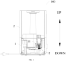
FIG. 1 is a schematic diagram showing a humidifier in accordance with an embodiment of the present invention. -
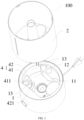
FIG. 2 is a schematic diagram showing a humidifier with a water tank separated in accordance with an embodiment of the present invention. -
FIG. 3 is a perspective view showing a humidifier in accordance with an embodiment of the present invention. -
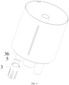
FIG. 4 is a schematic diagram showing a water tank in accordance with an embodiment of the present invention. -
FIG. 5 is a schematic diagram showing a bottom of a water tank in accordance with an embodiment of the present invention. -
FIG. 6 is a schematic diagram showing a float cover in accordance with an embodiment of the present invention. -
FIG. 7 is a schematic diagram showing a float cover in accordance with an embodiment of the present invention. - Reference numerals:
-
humidifier 100; -
pedestal 1,atomization chamber 11,first bottom wall 12,first side wall 13,positioning groove 14; -
water tank 2; - float limiter 30,
float cover 3,floating chamber 31, first throughhole 32, second throughhole 33,snap 34,slot 35,stopper 36,bottom 38 offloat cover 3,side wall 37 offloat cover 3; -
positioning member 4,first positioning plate 41,inner wall surface 411 offirst positioning plate 41,second positioning plate 42,inner wall surface 421 ofsecond positioning plate 42; -
float 5; -
sensor 6,first sensor 61,second sensor 62. - Embodiments of the present invention are described in detail below, and examples of the described embodiments are shown in accompanying drawings. The following embodiments described with reference to the accompanying drawings are exemplary and are intended to explain the present invention rather than limit the present invention.
- A
humidifier 100 according to embodiments of the present invention will be described below with reference to the accompanying drawings. As shown inFIGS. 1 to 7 , thehumidifier 100 according to embodiments of the present invention includes apedestal 1, awater tank 2, afloat 5 and a detection device. - The
water tank 2 is detachably mounted on a top of thepedestal 1. Thefloat 5 is on thewater tank 2 and is movable relative to thewater tank 2. The detection device is on thepedestal 1 and configured to detect a position of thefloat 5 in a preset space of thehumidifier 100, in which the position of thefloat 5 is used to indicate whether thewater tank 2 is separated from thepedestal 1 and whether thewater tank 2 is short of water. - For the
humidifier 100 according to the embodiments of the present invention, by arranging thefloat 5 on thewater tank 2 and making thefloat 5 movable relative to thewater tank 2, when thewater tank 2 is separated from thepedestal 1, thefloat 5 is also separated from thepedestal 1 along with thewater tank 2. That is, the separation of thefloat 5 from thepedestal 1 represents the separation of thewater tank 2 from thepedestal 1. When thewater tank 2 is mounted on the top of thepedestal 1, thefloat 5 floats up and down within the preset space of thehumidifier 100, and a floating position of thefloat 5 can indicate a water level in the preset space. Thefloat 5 floats up and down along with the water level in the humidifier 100 (thewater tank 2 or the pedestal 1). When thewater tank 2 is not short of water, the floating position of thefloat 5 in the preset space is higher; when thewater tank 2 is short of water, the floating position of thefloat 5 in the preset space is lower. - The position of the
float 5 is used to indicate whether thewater tank 2 is separated from thepedestal 1 and whether thewater tank 2 is short of water. The detection device is used to detect the position of thefloat 5 in the preset space of thehumidifier 100. Specifically, the detection device is used to detect a position, in an up-down direction, of thefloat 5 in the preset space of thehumidifier 100. When the detection device detects that thefloat 5 is below a lower water level in the preset space of thehumidifier 100, such information can be sent to a central control system to determine that thewater tank 2 is short of water. When the detection device detects that thefloat 5 is above the lower water level in the preset space of thehumidifier 100, such information can be sent to the central control system to determine that thewater tank 2 is not short of water. When the detection device detects that thefloat 5 is above a certain preset position in the preset space of thehumidifier 100 or that thefloat 5 is not in the preset space, it means that thefloat 5 is leaving the preset space of thehumidifier 100 or has already left the preset space of thehumidifier 100, and such information is sent to the central control system to determine that thewater tank 2 is separated from thepedestal 1. - When it is determined that the
water tank 2 is short of water or thewater tank 2 is separated from thepedestal 1, an atomizer and a fan can be turned off (after a preset time), reducing energy consumption of thehumidifier 100. Compared with the need for two sets of detection apparatuses in the related art, the present application only needs a single detection device to determine whether thewater tank 2 is separated from thepedestal 1 and whether thewater tank 2 is short of water by detecting the position of thefloat 5, decreasing the number of devices in thehumidifier 100 to improve production efficiency and reduce production costs. - Therefore, the
humidifier 100 according to the embodiments of the present invention has the advantages of high production efficiency, low production cost and low energy consumption. - As shown in
FIGS. 1 to 7 , thehumidifier 100 according to embodiments of the present invention includes thepedestal 1, thewater tank 2, a float limiter 30, thefloat 5 and the detection device. - As shown in
FIG. 1 ,FIG. 2 andFIG. 3 , thepedestal 1 has anatomization chamber 11, and liquid is atomized in theatomization chamber 11. Specifically, an opening of theatomization chamber 11 faces upwards; a housing of thepedestal 1 includes afirst bottom wall 12 and afirst side wall 13 that define theatomization chamber 11; and an outer edge of thefirst bottom wall 12 is coupled to a lower edge of thefirst side wall 13. The up-down direction is indicated by arrows inFIGS. 1 and2 . - As shown in
FIG. 1 andFIG. 2 , thewater tank 2 is detachably mounted on the top of thepedestal 1, and thewater tank 2 is used to deliver liquid to theatomization chamber 11. Specifically, a bottom plate of thewater tank 2 has a water delivery port in communication with theatomization chamber 11, and a valve body is provided at the water delivery port. - The float limiter 30 is on the
water tank 2 and can (extend into the atomization chamber 11) be fitted over the detection device, and thefloat 5 can be in the float limiter 30 and move (up and down) relative to the float limiter 30. As a result, when thewater tank 2 is separated from thepedestal 1, thefloat 5 is separated from theatomization chamber 11 along with the float limiter 30. That is, the separation of thefloat 5 from thepedestal 1 represents the separation of thewater tank 2 from thepedestal 1. When thewater tank 2 is mounted on the top of thepedestal 1, thefloat 5 can float in theatomization chamber 11. - The preset space of the
humidifier 100 is theatomization chamber 11, and the detection device can detect the position of thefloat 5 in the atomization chamber. Thefloat 5 has a first preset position and a second preset position in theatomization chamber 11, and the first preset position is higher than the second preset position. The detection device is on thepedestal 1, and the detection device is used to detect the position of thefloat 5 to determine whether thewater tank 2 is separated from thepedestal 1 and whether the atomization chamber 11 (the water tank 2) is short of water. When the detection device detects that the position of thefloat 5 in theatomization chamber 11 is higher than the first preset position in theatomization chamber 11, it is determined that thewater tank 2 is separated from thepedestal 1; when the detection device detects that the position of thefloat 5 in theatomization chamber 11 is lower than the second preset position in theatomization chamber 11, it is determined that thewater tank 2 is short of water. - Specifically, the first preset position is above the floating position of the
float 5 in theatomization chamber 11, that is, when thefloat 5 is floating in theatomization chamber 11 that is not short of water, thefloat 5 is also always below the first preset position. The detection device can be used to detect the position of thefloat 5 in theatomization chamber 11. As a result, when the detection device detects that thefloat 5 is above the first preset position or when the detection device cannot detect the presence of thefloat 5 in theatomization chamber 11, it means that thefloat 5 is separating or has been separated from theatomization chamber 11, and such information can be sent to the central control system to determine that thewater tank 2 is separated from thepedestal 1, in which case thehumidifier 100 can turn off the atomizer and the fan, reducing the energy consumption of thehumidifier 100. - When the
water tank 2 is mounted on the top of thepedestal 1, the floating position of thefloat 5 in the up-down direction in theatomization chamber 11 can represent the water level in theatomization chamber 11. Specifically, the second preset position is close to a bottom wall of theatomization chamber 11, and thefloat 5 being below the second preset position means that the water level in theatomization chamber 11 is close to the bottom wall of theatomization chamber 11, indicating that theatomization chamber 11 is short of water, i.e., thewater tank 2 is short of water. Therefore, when the detection device detects that thefloat 5 is below the second preset position, it means that the water level in theatomization chamber 11 is close to the bottom wall of theatomization chamber 11, and such information can be sent to the central control system, determining that the atomization chamber 11 (the water tank 2) is short of water, in order to turn off the atomizer and the fan (after a preset time), reducing the energy consumption of thehumidifier 100. - As shown in
FIG. 1 andFIG. 2 , in some embodiments, the detection device extends upward from the bottom wall of theatomization chamber 11, and thefloat 5 can surround (or be fitted over) the detection device. Specifically, thefloat 5 is annular, and thefloat 5 is around the detection device, so that the detection device is used to detect the position of thefloat 5. - In some embodiments, the
float 5 includes a base body and a magnetic portion, and the magnetic portion is on the base body. As a result, thefloat 5 is magnetic and has a density smaller than that of water, so that thefloat 5 can float in theatomization chamber 11. The detection device may be a Hall sensor or a magnetic reed switch. Thus, the Hall sensor or the magnetic reed switch can cooperate with the magnetic portion of thefloat 5 in order to detect the position of thefloat 5. For example, the detection device is a Hall sensor. - As shown in
FIG. 1 andFIG. 2 , the detection device includes afirst sensor 61 and asecond sensor 62, and thefirst sensor 61 is above thesecond sensor 62. For example, thefirst sensor 61 and thesecond sensor 62 are both Hall sensors, and each of thefirst sensor 61 and thesecond sensor 62 can realize magnetic induction with thefloat 5 around the sensors, so that the corresponding one of thefirst sensor 61 and thesecond sensor 62 can turn on or turn off a certain circuit, and the central control system can determine the position of thefloat 5. - The
second sensor 62 is used to detect whether the position of thefloat 5 in theatomization chamber 11 is lower than the second preset position, to determine whether the water tank 2 (the atomization chamber 11) is short of water. Specifically, when thesecond sensor 62 detects that the position of thefloat 5 in theatomization chamber 11 is lower than the second preset position, it is determined that the water tank 2 (the atomization chamber 11) is short of water. Thesecond sensor 62 may be at a predetermined position in theatomization chamber 11, so that when theatomization chamber 11 is short of water and thefloat 5 is below the second preset position, thesecond sensor 62 can detect the magnetism of thefloat 5 and determine the position of thefloat 5. For example, thesecond sensor 62 is below the second preset position, so that thesecond sensor 62 can detect the presence of thefloat 5 below the second preset position and send this information to the central control system to determine the shortage of water in the atomization chamber 11 (the water tank 2). - The
first sensor 61 is used to detect whether the position of thefloat 5 in theatomization chamber 11 is higher than the first preset position, to determine whether thewater tank 2 is separated from thepedestal 1. - In some embodiments, the
first sensor 61 may detect that the position of thefloat 5 in theatomization chamber 11 is higher than the first preset position. Thefirst sensor 61 is at a predetermined position in theatomization chamber 11. When thefloat 5 in theatomization chamber 11 is separated from theatomization chamber 11 and reaches above the first preset position, thefirst sensor 61 can detect the magnetism of thefloat 5 and determine the position of thefloat 5. That is, thefirst sensor 61 may detect that thefloat 5 is above the first preset position, which means that thefloat 5 in theatomization chamber 11 is separating from theatomization chamber 11 and thewater tank 2 is separating from thepedestal 1. For example, thefirst sensor 61 is above the first preset position and hence may detect that thefloat 5 in theatomization chamber 11 is above the first preset position and send this information to the central control system to determine the separation of thewater tank 2 from thepedestal 1. - As shown in
FIG. 1 andFIG. 2 , in some embodiments, thefirst sensor 61 detects that the position of thefloat 5 in theatomization chamber 11 is lower than the first preset position. Thefirst sensor 61 may detect that thefloat 5 is between the first preset position and the second preset position. Specifically, thefirst sensor 61 is at a predetermined position of theatomization chamber 11, so that when thefloat 5 is between the first preset position and the second preset position, thefirst sensor 61 can detect the magnetism of thefloat 5 and determine the position of thefloat 5. That is, when thefirst sensor 61 detects thefloat 5, it means that thefloat 5 floats in theatomization chamber 11 and theatomization chamber 11 is not short of water. - The
first sensor 61 may detect that thefloat 5 is not between the first preset position and the second preset position, and thesecond sensor 62 may detect that thefloat 5 is not below the second preset position. In such a way, it is determined that thefloat 5 is separated from theatomization chamber 11 and thewater tank 2 is separated from thepedestal 1. That is, when thefirst sensor 61 does not detect the presence of thefloat 5 between the first preset position and the second preset position and thesecond sensor 62 does not detect the presence of thefloat 5 below the second preset position, it means that thefloat 5 is not within detection ranges of thefirst sensor 61 and thesecond sensor 62, and thefirst sensor 61 and thesecond sensor 62 cannot detect whether theatomization chamber 11 is short of water. That is, thefloat 5 is taken away by thewater tank 2, and it is determined that thewater tank 2 is separated from thepedestal 1. - In some embodiments, the detection device includes a third sensor at a predetermined position in the
atomization chamber 11. For example, the third sensor may be at a bottom of theatomization chamber 11. The third sensor may be a Hall sensor, and the third sensor can realize magnetic induction with the magnetic portion of thefloat 5 and change a current level of a certain circuit within the third sensor according to the magnitude of the magnetism. The closer thefloat 5 is to the third sensor, the greater the magnetism sensed by the third sensor is. That is, the position of thefloat 5 can be determined by the current level of the circuit, and the position of thefloat 5 in the up-down direction can be determined. - The third sensor is used to detect whether the position of the
float 5 in theatomization chamber 11 is lower than the second preset position and whether the position of thefloat 5 in theatomization chamber 11 is higher than the first preset position, to determine whether thewater tank 2 is short of water and whether thewater tank 2 is separated from thepedestal 1. - The third sensor may detect that the position of the
float 5 in theatomization chamber 11 is below the second preset position and determine that theatomization chamber 11 is short of water. Specifically, when theatomization chamber 11 is short of water and thefloat 5 is below the second preset position, thefloat 5 is relatively close to the third sensor, and the magnetism of thefloat 5 detected by the third sensor is relatively great. Therefore, when the third sensor detects that the magnetism of thefloat 5 is greater than a preset value, it means that the third sensor detects that thefloat 5 is below the second preset position and sends this information to the central control system to determine the shortage of water in the atomization chamber 11 (the water tank 2). - The third sensor may detect that the position of the
float 5 in theatomization chamber 11 is above the first preset position and determine that thewater tank 2 is separated from thepedestal 1. Specifically, when thefloat 5 is above the first preset position, thefloat 5 is relatively far away from the third sensor and the magnetism of thefloat 5 detected by the third sensor is relatively small. Therefore, when the third sensor detects that the magnetism of thefloat 5 is smaller than a preset value, it means that the third sensor detects that thefloat 5 is above the first preset position and sends this information to the central control system to determine that thefloat 5 is separating from theatomization chamber 11 and thewater tank 2 is separating from thepedestal 1. - In some embodiments, the third sensor may detect that the
float 5 is not between the first preset position and the second preset position, and the third sensor may detect that thefloat 5 is not below the second preset position. As a result, it is determined that thewater tank 2 is separated from thepedestal 1. Specifically, when thefloat 5 is above the first preset position, thefloat 5 is far away from the third sensor, and the third sensor can hardly sense the magnetism of thefloat 5. When thefloat 5 is between the first preset position and the second preset position or when thefloat 5 is below the second preset position, the third sensor can sense the magnetism of thefloat 5 and determine the position of thefloat 5 according to the magnetism of thefloat 5. Therefore, when the third sensor cannot detect the magnetism of thefloat 5, thefloat 5 is not within a detection range of the third sensor, and the third sensor cannot determine whether theatomization chamber 11 is short of water, that is, thefloat 5 is taken away by thewater tank 2, and can send this information to the central control system to determine that thewater tank 2 is separated from thepedestal 1. - As shown in
FIG. 1 andFIG. 2 , in some embodiments, thefirst bottom wall 12 of thepedestal 1 at least partially protrudes upwards and forms apositioning groove 14 with a downward opening. Thepositioning groove 14 is spaced apart from theatomization chamber 11. The detection device is in thepositioning groove 14. The float limiter 30 may surround thepositioning groove 14, so that the float limiter 30 may be fitted over the detection device. Since thepositioning groove 14 is spaced apart from theatomization chamber 11, thepositioning groove 14 is not in communication with theatomization chamber 11, so that the detection device is not in contact with the water in theatomization chamber 11 and can be protected. In some embodiments, thefirst sensor 61 and thesecond sensor 62 are both in thepositioning groove 14. That is, a protrudingportion 15 of thefirst bottom wall 12 defines thepositioning groove 14. In this way, thefirst sensor 61 and thesecond sensor 62 can be prevented from directly contacting the liquid in theatomization chamber 11, and it is convenient to detect thefloat 5. For example, thefirst sensor 61 is in thepositioning groove 14 and away from the opening of thepositioning groove 14, and thesecond sensor 62 is in thepositioning groove 14 and adjacent to the downward opening of thepositioning groove 14. - In some embodiments, the third sensor is in the
positioning groove 14, that is, the protrudingportion 15 of thefirst bottom wall 12 defines thepositioning groove 14. In this way, the third sensor can be prevented from directly contacting the liquid in theatomization chamber 11, and it is convenient to detect thefloat 5. For example, the third sensor is adjacent to the downward opening of thepositioning groove 14. - As shown in
FIG. 1 to FIG. 7 , in some embodiments, the float limiter 30 includes afloat cover 3, and thefloat cover 3 is detachably mounted to a bottom of thewater tank 2. - The
float cover 3 may be fitted over the detection device. Thefloat cover 3 has a floatingchamber 31 in communication with theatomization chamber 11, and thefloat 5 can move along the up-down direction in the floatingchamber 31. Specifically, a bottom 38 of thefloat cover 3 has a first throughhole 32, and the detection device may be inserted into the first throughhole 32, so that thefloat cover 3 can be fitted over the protrudingportion 15, that is, the protrudingportion 15 can enter the floatingchamber 31 of thefloat cover 3 through the first throughhole 32, and the float can move up and down around the protrudingportion 15 conveniently. Therefore, a distance between the float and the detection device (thefirst sensor 61 and the second sensor 62) can become small, and the detection device can detect the position of thefloat 5 conveniently. - As shown in
FIG. 6 andFIG. 7 , thefloat cover 3 has a plurality of second throughholes 33, and the floatingchamber 31 is in communication with theatomization chamber 11 through the second through holes 33. The plurality of second throughholes 33 are along a peripheral direction of thefloat cover 3, and each second throughhole 33 is in the bottom 38 of thefloat cover 3 and in theside wall 37 of thefloat cover 3. Specifically, each second throughhole 33 extends upwards from a bottom surface of thefloat cover 3 and penetrates theside wall 37 of thefloat cover 3 in an inner-outer direction of thefloat cover 3, in which the inner-outer direction is perpendicular to the up-down direction. The floatingchamber 31 is inside thefloat cover 3. Each second throughhole 33 penetrates the bottom surface of thefloat cover 3 in the up-down direction and penetrates theside wall 37 of thefloat cover 3 in the inner-outer direction of thefloat cover 3, so that the floatingchamber 31 is in communication with theatomization chamber 11 through the second through holes 33. As a result, it is convenient for the liquid in theatomization chamber 11 to enter the floatingchamber 31, and a water level in the floatingchamber 31 is consistent with the water level in theatomization chamber 11. - As shown in
FIG. 4 andFIG. 5 , in some embodiments, the float limiter 30 further includes astopper 36; thestopper 36 is at the bottom of thewater tank 2 and extends downwards by a predetermined amount; and thestopper 36 is within the floatingchamber 31 and above thefloat 5. In such way, thestopper 36 can cooperate with the bottom of thefloat cover 3 to limit the position of thefloat 5 in the up-down direction, to limit the position of thefloat 5 floating in theatomization chamber 11, and facilitate the arrangement of the detection device (thefirst sensor 61 and the second sensor 62). - As shown in
FIGS. 5 and7 , in some embodiments, one of a top of thefloat cover 3 and the bottom of thewater tank 2 includes asnap 34, and the other of the top of thefloat cover 3 and the bottom of thewater tank 2 includes aslot 35 fitted with thesnap 34. Specifically, thesnap 34 may be snapped in theslot 35, so that thefloat cover 3 may be coupled to thewater tank 2. For example, an inner wall surface of the top of thefloat cover 3 includes thesnap 34, and a lower surface of the bottom of thewater tank 2 includes theslot 35. - In some embodiments, the float limiter 30 includes a limiting tube (not shown) extending in the up-down direction, and a top of the limiting tube is coupled to the bottom of the
water tank 2. An outer surface of a middle portion of the limiting tube is recessed inwards to form a chute, and thefloat 5 is annular and is movably fitted in the chute along the up-down direction. In this way, the chute can limit the position of thefloat 5 in the up-down direction, the position of thefloat 5 floating in theatomization chamber 11 can be limited conveniently, and the arrangement of the detection device (thefirst sensor 61 and the second sensor 62) can be facilitated. Moreover, the protrudingportion 15 extends into the limiting tube, so that it is convenient for the float to move up and down around the protrudingportion 15. The distance between the float and the detection device (thefirst sensor 61 and the second sensor 62) can become small, and the detection device can detect the position of thefloat 5 conveniently. - In some embodiments, the limiting tube includes a first tube segment, a second tube segment, and a third tube segment connected in sequence, and each of the first tube segment, the second tube segment, and the third tube segment extends in the up-down direction. A top of the first tube segment is coupled to the bottom of the
water tank 2. A diameter of the second tube segment is smaller than a diameter of the first tube segment and a diameter of the third tube segment, so that the first tube segment, the second tube segment and the third tube segment define the chute, and thefloat 5 is fitted over the second tube segment and movable in the up-down direction. - In some embodiments, the detection device includes a camera. The camera can capture an image of the
float 5 in theatomization chamber 11 and transmit it to the central control system, to detect the position of thefloat 5. It is convenient for the detection device to detect the position of thefloat 5 and determine whether thewater tank 2 is separated from thepedestal 1 and whether the water tank 2 (the atomization chamber 11) is short of water. - As shown in
FIGS. 1 to 3 , in some embodiments, thehumidifier 100 according to the embodiments of the present invention further includes apositioning member 4. An inner wall surface of thepositioning member 4 and a side wall of theatomization chamber 11 define a guide groove with an upward opening. The guide groove constitutes a part of theatomization chamber 11 and is used to guide the float limiter 30. Specifically, the positioningmember 4 includes afirst positioning plate 41 and asecond positioning plate 42 at the bottom of theatomization chamber 11. Thefirst positioning plate 41 is spaced apart from thesecond positioning plate 42. Thefirst positioning plate 41 and thesecond positioning plate 42 are spaced apart so that the water can enter the guide groove from a passage between thefirst positioning plate 41 and thesecond positioning plate 42. The water can easily enter the guide groove and a water level in the guide groove is consistent with the water level of theatomization chamber 11. Aninner wall surface 411 of thefirst positioning plate 41 and aninner wall surface 421 of thesecond positioning plate 42 are both arc-shaped surfaces, and the arc-shaped surfaces extend in the up-down direction. Theinner wall surface 411 of thefirst positioning plate 41, theinner wall surface 421 of thesecond positioning plate 42, and the side wall of the atomization chamber 11 (a part of the first side wall 13) define the guide groove, which makes it convenient for the float limiter 30 (the float cover 3) to reach a correct position. - In the description of the present invention, it shall be understood that terms such as "central," "longitudinal," "transverse," "length," "width," "thickness," "upper," "lower," "front," "rear," "left," "right," "vertical," "horizontal," "top," "bottom," "inner," "outer," "clockwise," "counterclockwise," "axial," "radial" and "circumferential" should be construed to refer to the orientation as then described or as shown in the drawings under discussion. These relative terms are for convenience of description and do not indicate or imply that the device or element referred to must have a particular orientation, or be constructed and operated in a particular orientation. Thus, these terms shall not be construed as limitation on the present invention.
- In addition, terms such as "first" and "second" are merely used for descriptive purposes and cannot be understood as indicating or implying relative importance or the number of technical features indicated. Thus, the features associated with "first" and "second" may explicitly or implicitly include at least one of the features. In the description of the present invention, unless otherwise specifically defined, "a plurality of' means at least two, such as two, three, etc.
- In the present invention, unless otherwise explicitly specified and defined, the terms "mounted," "coupled," "connected," "fixed" and the like are used broadly, and may be, for example, fixed connections, detachable connections, or integral connections; may also be mechanical or electrical connections or intercommunication; may also be direct connections or indirect connections via intermediate media; may also be inner communications or interactions of two elements. For those skilled in the art, the specific meaning of the above terms in the present invention can be understood according to the specific circumstances.
- In the present invention, unless otherwise explicitly specified and defined, a structure in which a first feature is "on" or "below" a second feature may include an embodiment in which the first feature is in direct contact with the second feature, and may also include an embodiment in which the first feature and the second feature are not in direct contact with each other, but are contacted via an intermediate medium formed therebetween. Furthermore, a first feature "on," "above," or "on top of' a second feature may include an embodiment in which the first feature is right or obliquely "on," "above," or "on top of' the second feature, or just means that the first feature is at a height higher than that of the second feature; while a first feature "below," "under," or "on bottom of' a second feature may include an embodiment in which the first feature is right or obliquely "below," "under," or "on bottom of' the second feature, or just means that the first feature is at a height lower than that of the second feature.
- In the present invention, terms such as "an embodiment," "some embodiments," "an example," "a specific example," or "some examples," means that a particular feature, structure, material, or characteristic described in connection with the embodiment or example is included in at least one embodiment or example of the present invention. Thus, the appearances of these terms in various places throughout this specification are not necessarily referring to the same embodiment or example of the present invention. Furthermore, the particular features, structures, materials, or characteristics may be combined in any suitable manner in one or more embodiments or examples. In addition, without contradiction, those skilled in the art may combine and unite different embodiments or examples or features of the different embodiments or examples described in this specification.
- Although the above embodiments have been shown and described, it can be
understood that the above embodiments are exemplary and shall not be understood as limitation to the present invention, and changes, modifications, alternatives and variations can
be made in the above embodiments within the scope of the appended claims.
Claims (15)
- A humidifier (100), comprising:a pedestal (1);a water tank (2) detachably mounted on a top of the pedestal (1);a float (5) on the water tank (2) and movable relative to the water tank (2); anda detection device on the pedestal (1) and configured to detect a position of the float (5) in a preset space of the humidifier (100), wherein the position of the float (5) indicates whether at least one of: (i) the water tank (2) is separated from the pedestal (1) and (ii) the water tank (2) is short of water.
- The humidifier (100) according to claim 1, wherein:the pedestal (1) has an atomization chamber (11), and the float (5) is movable into the atomization chamber (11), the preset space of the humidifier (100) being the atomization chamber (11);the water tank (2) is determined to be separated from the pedestal (1) in response to detecting, by the detection device, that a position of the float (5) in the atomization chamber (11) is higher than a first preset position in the atomization chamber (11); the water tank (2) is determined to be short of water in response to detecting, by the detection device, that the position of the float (5) in the atomization chamber (11) is lower than a second preset position in the atomization chamber (11); and the first preset position is higher than the second preset position.
- The humidifier (100) according to claim 2, wherein:the detection device comprises a first sensor (61) and a second sensor (62), the first sensor (61) being above the second sensor (62); andthe second sensor (62) is configured to detect whether the position of the float (5) in the atomization chamber (11) is lower than the second preset position, and the first sensor (61) is configured to detect whether the position of the float (5) in the atomization chamber (11) is higher than the first preset position.
- The humidifier (100) according to claim 2 or 3, wherein the detection device comprises a third sensor configured to detect whether the position of the float (5) in the atomization chamber (11) is lower than the second preset position and whether the position of the float (5) in the atomization chamber (11) is higher than the first preset position.
- The humidifier (100) according to any one of claims 1 to 4, further comprising a float limiter (30) on the water tank (2) and fitted over the detection device, wherein the float (5) is within the float limiter (30) and is movable relative to the float limiter (30).
- The humidifier (100) according to claim 5, wherein:the float limiter (30) comprises a float cover (3) detachably mounted to a bottom of the water tank (2) and fitted over the detection device; andthe float cover (3) has a floating chamber (31), and the float (5) is movable along an up-down direction in the floating chamber (31).
- The humidifier (100) according to claim 6, wherein:the float cover (3) has a first through hole (32) in a bottom (38) of the float cover (3), and the detection device is insertable into the first through hole (32); andthe float cover (3) has a plurality of second through holes (33), and the floating chamber (31) is in communication with an atomization chamber (11) of the pedestal (1) by the plurality of second through holes (33),optionally, the plurality of second through holes (33) are along a peripheral direction of the float cover (3),more optionally, each of the plurality of second through holes (33) penetrates a bottom surface of the float cover (3) in the up-down direction and penetrates a side wall (37) of the float cover (3) in an inner-outer direction of the float cover (3), the inner-outer direction of the float cover (3) being perpendicular to the up-down direction.
- The humidifier (100) according to any one of claims 5 to 7, wherein:the pedestal (1) comprises a first bottom wall (12), and the first bottom wall (12) at least partially protrudes upwards and forms a positioning groove (14) with a downward opening; andthe detection device is in the positioning groove (14), and the float limiter (30) surrounds the positioning groove (14).
- The humidifier (100) according to any one of claims 6 to 8, wherein the float limiter (30) comprises a stopper (36) at the bottom of the water tank (2) and extending downwards by a predetermined amount, and the stopper (36) is within the floating chamber (31) and above the float (5).
- The humidifier (100) according to any one of claims 6 to 9, wherein one of a top of the float cover (3) and the bottom of the water tank (2) comprises a snap (34), and the other of the top of the float cover (3) and the bottom of the water tank (2) comprises a slot (35) fitted with the snap (34).
- The humidifier (100) according to any one of claim 5 to 10, wherein:the float limiter (30) comprises a limiting tube extending in an up-down direction, and a top of the limiting tube is coupled to a bottom of the water tank (2); andan outer surface of a middle portion of the limiting tube is recessed inwards and forms a chute, and the float (5) is annular and is fitted in the chute and movable along the up-down direction.
- The humidifier (100) according to claim 11, wherein:the limiting tube comprises a first tube segment, a second tube segment, and a third tube segment connected in sequence;a top of the first tube segment is coupled to the bottom of the water tank (2);a diameter of the second tube segment is smaller than a diameter of the first tube segment and a diameter of the third tube segment, and the first tube segment, the second tube segment and the third tube segment define the chute; andthe float (5) is fitted over the second tube segment and movable along the up-down direction.
- The humidifier (100) according to any one of claims 5 to 12, further comprising a positioning member (4),
wherein an inner wall surface of the positioning member and a side wall of an atomization chamber (11) of the pedestal (1) define a guide groove with an upward opening; and the guide groove constitutes a part of the atomization chamber (11) and guides the float limiter (30). - The humidifier (100) according to claim 13, wherein:the positioning member comprises a first positioning plate (41) and a second positioning plate (42) at a bottom of the atomization chamber (11), and the first positioning plate is spaced apart from the second positioning plate;an inner wall surface (411) of the first positioning plate and an inner wall surface (421) of the second positioning plate are both arc-shaped surfaces; andthe inner wall surface of the first positioning plate, the inner wall surface of the second positioning plate, and the side wall of the atomization chamber (11) define the guide groove.
- The humidifier (100) according to any one of claims 1 to 14, wherein:the float (5) comprises a base body and a magnetic portion, and the magnetic portion is on the base body; andthe detection device is a Hall sensor or a magnetic reed switch.
Applications Claiming Priority (1)
| Application Number | Priority Date | Filing Date | Title |
|---|---|---|---|
| CN202210344787.8A CN114719364A (en) | 2022-03-31 | 2022-03-31 | Humidifier |
Publications (2)
| Publication Number | Publication Date |
|---|---|
| EP4253851A1 true EP4253851A1 (en) | 2023-10-04 |
| EP4253851B1 EP4253851B1 (en) | 2025-09-24 |
Family
ID=82241047
Family Applications (1)
| Application Number | Title | Priority Date | Filing Date |
|---|---|---|---|
| EP22187589.1A Active EP4253851B1 (en) | 2022-03-31 | 2022-07-28 | Humidifier |
Country Status (5)
| Country | Link |
|---|---|
| US (1) | US12422153B2 (en) |
| EP (1) | EP4253851B1 (en) |
| JP (1) | JP7460702B2 (en) |
| KR (1) | KR102658109B1 (en) |
| CN (1) | CN114719364A (en) |
Families Citing this family (4)
| Publication number | Priority date | Publication date | Assignee | Title |
|---|---|---|---|---|
| CN114719364A (en) * | 2022-03-31 | 2022-07-08 | 北京小米移动软件有限公司 | Humidifier |
| CN115899906A (en) * | 2022-11-15 | 2023-04-04 | 中山市宏冠西联电气科技有限公司 | A humidifier and floor fan with improved control |
| CN221057220U (en) * | 2023-10-30 | 2024-05-31 | 深圳市晨北科技有限公司 | Magnetic ring assembly, water tank assembly and humidifier |
| CN118052820B (en) * | 2024-04-16 | 2024-07-02 | 沈阳迈思医疗科技有限公司 | Water level detection method, device, equipment, storage medium and system |
Citations (3)
| Publication number | Priority date | Publication date | Assignee | Title |
|---|---|---|---|---|
| EP1260772A1 (en) * | 2001-05-15 | 2002-11-27 | Chen Pan Huang | Humidifier |
| KR200438801Y1 (en) * | 2006-12-28 | 2008-03-06 | 주식회사 노비타 | Water level sensor with safety switch |
| WO2008060089A1 (en) * | 2006-11-13 | 2008-05-22 | Daekyu Bak | Easy-cleaning ultrasonic humidifier |
Family Cites Families (53)
| Publication number | Priority date | Publication date | Assignee | Title |
|---|---|---|---|---|
| JPS59119126A (en) * | 1982-12-24 | 1984-07-10 | Toshiba Corp | Humidifier |
| JPH05296505A (en) * | 1992-04-24 | 1993-11-09 | Sanyo Electric Co Ltd | Humidifier |
| JP2000266370A (en) * | 1999-03-15 | 2000-09-29 | Aiwa Co Ltd | Humidifier |
| US20040108604A1 (en) * | 2000-06-21 | 2004-06-10 | Pan Huang Chuan | Water level control device for a humidifier |
| US7182321B2 (en) * | 2004-12-02 | 2007-02-27 | Chuan-Pan Huang | Safety device for a humidifier |
| US20070152356A1 (en) * | 2005-12-30 | 2007-07-05 | Ping Huang | Humidifier structure |
| CN201853651U (en) * | 2010-08-26 | 2011-06-01 | 珠海格力电器股份有限公司 | Power-off protection device for humidifier |
| WO2012091369A2 (en) * | 2010-12-29 | 2012-07-05 | Woongjin Coway Co., Ltd | Humidification apparatus |
| US8844908B2 (en) * | 2011-03-01 | 2014-09-30 | Fka Distributing Co. | Humidifier |
| KR20130059164A (en) * | 2011-11-28 | 2013-06-05 | 주식회사 위닉스 | Water level sensing apparatus of dehumidifier |
| JP6352240B2 (en) | 2012-03-30 | 2018-07-04 | フィッシャー アンド ペイケル ヘルスケア リミテッド | Humidification system |
| CN203083660U (en) * | 2013-01-28 | 2013-07-24 | 卢生成 | Water level induction structure of humidifier |
| CH708642A1 (en) * | 2013-09-23 | 2015-03-31 | Plaston Ag | Luftwasch- or air lighting device with a silencer module. |
| CN103604187B (en) * | 2013-11-14 | 2016-02-17 | 上海奔腾电工有限公司 | One adds water ultrasonic humidifier |
| US20150153058A1 (en) * | 2013-11-29 | 2015-06-04 | Roolen Co., Ltd. | Humidifier with Automatic Humidification Control |
| EP3213787B1 (en) * | 2014-06-10 | 2019-01-09 | Stamford Devices Limited | An aerosol delivery system with humidification |
| CN204285709U (en) | 2014-10-30 | 2015-04-22 | 厦门蒙发利健康科技有限公司 | A kind of safety-type air humidifier |
| US10578325B2 (en) * | 2014-11-25 | 2020-03-03 | Great Innovations, LLC | Humidifier with water flow control between an upper tank and a lower reservoir |
| CN204853787U (en) * | 2015-06-05 | 2015-12-09 | 佛山市金星徽电器有限公司 | Go up and add ability of swimming humidifier |
| US10113759B2 (en) * | 2015-10-30 | 2018-10-30 | Lg Electronics Inc. | Air conditioner and control method thereof |
| KR101949354B1 (en) * | 2015-10-30 | 2019-05-10 | 엘지전자 주식회사 | apparatus for both humidification and air cleaning |
| KR101769817B1 (en) * | 2015-10-30 | 2017-08-30 | 엘지전자 주식회사 | apparatus for both humidification and air cleaning |
| CN205579831U (en) * | 2016-04-08 | 2016-09-14 | 广东美的制冷设备有限公司 | Air humidifier |
| CN205536331U (en) * | 2016-04-12 | 2016-08-31 | 珠海格力电器股份有限公司 | Humidifier and water tank assembly thereof |
| KR20170139283A (en) * | 2016-06-09 | 2017-12-19 | 부산대학교 산학협력단 | The method and measuring instrumentation of water level for liquid storage tank |
| CN206073341U (en) * | 2016-08-30 | 2017-04-05 | 上海奔腾电工有限公司 | Add water in one kind humidifier |
| CN106642518B (en) * | 2016-09-14 | 2020-06-19 | 北京小米移动软件有限公司 | Water shortage detection method and device of humidifier |
| CN206478796U (en) * | 2016-12-23 | 2017-09-08 | 珠海格力电器股份有限公司 | Go out fog subassembly and refrigerating plant |
| CA2990498A1 (en) * | 2016-12-28 | 2018-06-28 | Pure Humidifier Company | Modulating makeup fluid control systems and methods for same |
| CN107062496B (en) * | 2017-01-15 | 2022-01-28 | 广东德尔玛科技股份有限公司 | Humidifier with purifier |
| CN206786957U (en) * | 2017-05-02 | 2017-12-22 | 小熊电器股份有限公司 | Add water ultrasonic humidifier in one kind |
| US20190041084A1 (en) * | 2017-08-01 | 2019-02-07 | D-M-S Holdings, Inc. | Humidifier reservoir fluid control |
| US20190041086A1 (en) * | 2017-08-01 | 2019-02-07 | D-M-S Holdings, Inc. | Humidifier liquid tank |
| CN207094926U (en) | 2017-08-21 | 2018-03-13 | 深圳前海帕拓逊网络技术有限公司 | A kind of humidifier with power-off protection function |
| CN107525194A (en) * | 2017-08-23 | 2017-12-29 | 陈甘霖 | It is a kind of to carry the upper plus water humidifier for leading mist purifier |
| CN107655131A (en) * | 2017-10-25 | 2018-02-02 | 佛山市腾联电器有限公司 | A kind of new type ultrasonic air humidifier |
| JP7265265B2 (en) * | 2017-12-04 | 2023-04-26 | 株式会社カンキョー | ultrasonic humidifier |
| KR102186444B1 (en) * | 2018-01-19 | 2020-12-04 | 엘지전자 주식회사 | Apparatus for both humidification and air cleaning |
| US20200096213A1 (en) * | 2018-09-20 | 2020-03-26 | Jingqing Liang | Humidifier with a top water-feeding structure |
| US20200103140A1 (en) * | 2018-09-27 | 2020-04-02 | Guardian Technologies Llc | Humidifier water filter |
| CN109405110B (en) * | 2018-10-11 | 2020-09-29 | 珠海格力电器股份有限公司 | Air treatment device and control method |
| GB201900018D0 (en) * | 2019-01-02 | 2019-02-13 | Dyson Technology Ltd | Air treatment apparatus |
| CN109869858A (en) * | 2019-01-30 | 2019-06-11 | 深圳市晨北科技有限公司 | humidifier |
| CN211233278U (en) * | 2019-12-14 | 2020-08-11 | 珠海格力电器股份有限公司 | Humidifier |
| DE102020112573A1 (en) * | 2020-05-08 | 2021-11-11 | Woco Gmbh & Co. Kg | Air treatment device with electrodeposition function |
| WO2022039485A1 (en) * | 2020-08-20 | 2022-02-24 | 애터미주식회사 | Smart humidifier |
| US12270567B2 (en) * | 2020-08-31 | 2025-04-08 | Dirk Niedermann | Portable air treatment apparatus |
| CN113154574A (en) * | 2021-03-26 | 2021-07-23 | 深圳市晨北科技有限公司 | Humidifying equipment |
| US20230149659A1 (en) * | 2021-11-14 | 2023-05-18 | Shanghai Sunpai Trading Limited | Multifunctional aromatherapy machine |
| CN116234124A (en) * | 2021-12-06 | 2023-06-06 | 开利公司 | Interactive night lamp with air cleaning function |
| EP4365500A4 (en) * | 2021-12-29 | 2024-11-20 | Samsung Electronics Co., Ltd. | HUMIDIFIER AND HOUSEHOLD APPLIANCE |
| CN114719364A (en) * | 2022-03-31 | 2022-07-08 | 北京小米移动软件有限公司 | Humidifier |
| CN114608190B (en) * | 2022-04-08 | 2023-06-06 | 佛山市南海科日超声电子有限公司 | A water supply device for a humidifier |
-
2022
- 2022-03-31 CN CN202210344787.8A patent/CN114719364A/en active Pending
- 2022-07-26 KR KR1020220092392A patent/KR102658109B1/en active Active
- 2022-07-27 US US17/875,165 patent/US12422153B2/en active Active
- 2022-07-28 EP EP22187589.1A patent/EP4253851B1/en active Active
- 2022-07-29 JP JP2022121667A patent/JP7460702B2/en active Active
Patent Citations (3)
| Publication number | Priority date | Publication date | Assignee | Title |
|---|---|---|---|---|
| EP1260772A1 (en) * | 2001-05-15 | 2002-11-27 | Chen Pan Huang | Humidifier |
| WO2008060089A1 (en) * | 2006-11-13 | 2008-05-22 | Daekyu Bak | Easy-cleaning ultrasonic humidifier |
| KR200438801Y1 (en) * | 2006-12-28 | 2008-03-06 | 주식회사 노비타 | Water level sensor with safety switch |
Also Published As
| Publication number | Publication date |
|---|---|
| CN114719364A (en) | 2022-07-08 |
| US12422153B2 (en) | 2025-09-23 |
| US20230314017A1 (en) | 2023-10-05 |
| JP2023152263A (en) | 2023-10-16 |
| KR102658109B1 (en) | 2024-04-17 |
| KR20230141393A (en) | 2023-10-10 |
| EP4253851B1 (en) | 2025-09-24 |
| JP7460702B2 (en) | 2024-04-02 |
Similar Documents
| Publication | Publication Date | Title |
|---|---|---|
| EP4253851A1 (en) | Humidifier | |
| CN216846411U (en) | Liquid tank and apparatus including the same | |
| US10739026B2 (en) | Ventilating fan | |
| US20220205672A1 (en) | Humidifier | |
| JP2017147159A (en) | Gas-liquid separator | |
| KR102312878B1 (en) | Cooking Container Detecting Apparatus | |
| CN219572215U (en) | Wire controller and air conditioner | |
| CN108775686B (en) | Display box, panel assembly having the same, and air conditioner indoor unit | |
| CN218121096U (en) | Water level detection device and electric appliance with water generation function | |
| CN220937927U (en) | A cleaning robot | |
| US12465080B2 (en) | Electronic vaporization device and power supply assembly thereof | |
| CN205579831U (en) | Air humidifier | |
| CN203447145U (en) | Water dispenser | |
| CN115824351B (en) | Liquid level probe assembly, liquid tank and equipment including liquid tank | |
| KR102749226B1 (en) | Device for generating aerosol | |
| CN219455261U (en) | Electrical equipment with liquid level sensor | |
| CN204718624U (en) | Sensor mounting box | |
| CN203100834U (en) | Water level detection floater for kitchen appliance and kitchen appliance | |
| CN223153689U (en) | Fresh air module and air conditioner | |
| CN218097863U (en) | Air detection assembly for air conditioning system and air conditioning system having same | |
| US20160238431A1 (en) | Liquid surface sensor | |
| CN223024713U (en) | Wire controller | |
| CN215724018U (en) | A multifunctional sensor device | |
| KR102865525B1 (en) | Device for generating aerosol | |
| KR102857537B1 (en) | Device for generating aerosol |
Legal Events
| Date | Code | Title | Description |
|---|---|---|---|
| PUAI | Public reference made under article 153(3) epc to a published international application that has entered the european phase |
Free format text: ORIGINAL CODE: 0009012 |
|
| STAA | Information on the status of an ep patent application or granted ep patent |
Free format text: STATUS: REQUEST FOR EXAMINATION WAS MADE |
|
| 17P | Request for examination filed |
Effective date: 20220728 |
|
| AK | Designated contracting states |
Kind code of ref document: A1 Designated state(s): AL AT BE BG CH CY CZ DE DK EE ES FI FR GB GR HR HU IE IS IT LI LT LU LV MC MK MT NL NO PL PT RO RS SE SI SK SM TR |
|
| GRAP | Despatch of communication of intention to grant a patent |
Free format text: ORIGINAL CODE: EPIDOSNIGR1 |
|
| STAA | Information on the status of an ep patent application or granted ep patent |
Free format text: STATUS: GRANT OF PATENT IS INTENDED |
|
| INTG | Intention to grant announced |
Effective date: 20250508 |
|
| GRAS | Grant fee paid |
Free format text: ORIGINAL CODE: EPIDOSNIGR3 |
|
| GRAA | (expected) grant |
Free format text: ORIGINAL CODE: 0009210 |
|
| STAA | Information on the status of an ep patent application or granted ep patent |
Free format text: STATUS: THE PATENT HAS BEEN GRANTED |
|
| AK | Designated contracting states |
Kind code of ref document: B1 Designated state(s): AL AT BE BG CH CY CZ DE DK EE ES FI FR GB GR HR HU IE IS IT LI LT LU LV MC MK MT NL NO PL PT RO RS SE SI SK SM TR |
|
| REG | Reference to a national code |
Ref country code: GB Ref legal event code: FG4D |
|
| REG | Reference to a national code |
Ref country code: CH Ref legal event code: EP |
|
| REG | Reference to a national code |
Ref country code: DE Ref legal event code: R096 Ref document number: 602022021859 Country of ref document: DE |
|
| REG | Reference to a national code |
Ref country code: IE Ref legal event code: FG4D |
|
| PG25 | Lapsed in a contracting state [announced via postgrant information from national office to epo] |
Ref country code: NO Free format text: LAPSE BECAUSE OF FAILURE TO SUBMIT A TRANSLATION OF THE DESCRIPTION OR TO PAY THE FEE WITHIN THE PRESCRIBED TIME-LIMIT Effective date: 20251224 |
|
| REG | Reference to a national code |
Ref country code: LT Ref legal event code: MG9D |
|
| PG25 | Lapsed in a contracting state [announced via postgrant information from national office to epo] |
Ref country code: FI Free format text: LAPSE BECAUSE OF FAILURE TO SUBMIT A TRANSLATION OF THE DESCRIPTION OR TO PAY THE FEE WITHIN THE PRESCRIBED TIME-LIMIT Effective date: 20250924 |
|
| PG25 | Lapsed in a contracting state [announced via postgrant information from national office to epo] |
Ref country code: HR Free format text: LAPSE BECAUSE OF FAILURE TO SUBMIT A TRANSLATION OF THE DESCRIPTION OR TO PAY THE FEE WITHIN THE PRESCRIBED TIME-LIMIT Effective date: 20250924 |
|
| PG25 | Lapsed in a contracting state [announced via postgrant information from national office to epo] |
Ref country code: GR Free format text: LAPSE BECAUSE OF FAILURE TO SUBMIT A TRANSLATION OF THE DESCRIPTION OR TO PAY THE FEE WITHIN THE PRESCRIBED TIME-LIMIT Effective date: 20251225 |
|
| PG25 | Lapsed in a contracting state [announced via postgrant information from national office to epo] |
Ref country code: SE Free format text: LAPSE BECAUSE OF FAILURE TO SUBMIT A TRANSLATION OF THE DESCRIPTION OR TO PAY THE FEE WITHIN THE PRESCRIBED TIME-LIMIT Effective date: 20250924 |
|
| PG25 | Lapsed in a contracting state [announced via postgrant information from national office to epo] |
Ref country code: LV Free format text: LAPSE BECAUSE OF FAILURE TO SUBMIT A TRANSLATION OF THE DESCRIPTION OR TO PAY THE FEE WITHIN THE PRESCRIBED TIME-LIMIT Effective date: 20250924 |
|
| PG25 | Lapsed in a contracting state [announced via postgrant information from national office to epo] |
Ref country code: BG Free format text: LAPSE BECAUSE OF FAILURE TO SUBMIT A TRANSLATION OF THE DESCRIPTION OR TO PAY THE FEE WITHIN THE PRESCRIBED TIME-LIMIT Effective date: 20250924 |
|
| PG25 | Lapsed in a contracting state [announced via postgrant information from national office to epo] |
Ref country code: RS Free format text: LAPSE BECAUSE OF FAILURE TO SUBMIT A TRANSLATION OF THE DESCRIPTION OR TO PAY THE FEE WITHIN THE PRESCRIBED TIME-LIMIT Effective date: 20251224 |
|
| REG | Reference to a national code |
Ref country code: NL Ref legal event code: MP Effective date: 20250924 |
|
| PG25 | Lapsed in a contracting state [announced via postgrant information from national office to epo] |
Ref country code: NL Free format text: LAPSE BECAUSE OF FAILURE TO SUBMIT A TRANSLATION OF THE DESCRIPTION OR TO PAY THE FEE WITHIN THE PRESCRIBED TIME-LIMIT Effective date: 20250924 |
|
| REG | Reference to a national code |
Ref country code: AT Ref legal event code: MK05 Ref document number: 1840595 Country of ref document: AT Kind code of ref document: T Effective date: 20250924 |
|
| PG25 | Lapsed in a contracting state [announced via postgrant information from national office to epo] |
Ref country code: SM Free format text: LAPSE BECAUSE OF FAILURE TO SUBMIT A TRANSLATION OF THE DESCRIPTION OR TO PAY THE FEE WITHIN THE PRESCRIBED TIME-LIMIT Effective date: 20250924 |
|
| PG25 | Lapsed in a contracting state [announced via postgrant information from national office to epo] |
Ref country code: ES Free format text: LAPSE BECAUSE OF FAILURE TO SUBMIT A TRANSLATION OF THE DESCRIPTION OR TO PAY THE FEE WITHIN THE PRESCRIBED TIME-LIMIT Effective date: 20250924 |
|
| PG25 | Lapsed in a contracting state [announced via postgrant information from national office to epo] |
Ref country code: AT Free format text: LAPSE BECAUSE OF FAILURE TO SUBMIT A TRANSLATION OF THE DESCRIPTION OR TO PAY THE FEE WITHIN THE PRESCRIBED TIME-LIMIT Effective date: 20250924 |
|
| PG25 | Lapsed in a contracting state [announced via postgrant information from national office to epo] |
Ref country code: IT Free format text: LAPSE BECAUSE OF FAILURE TO SUBMIT A TRANSLATION OF THE DESCRIPTION OR TO PAY THE FEE WITHIN THE PRESCRIBED TIME-LIMIT Effective date: 20250924 |
|
| PG25 | Lapsed in a contracting state [announced via postgrant information from national office to epo] |
Ref country code: IS Free format text: LAPSE BECAUSE OF FAILURE TO SUBMIT A TRANSLATION OF THE DESCRIPTION OR TO PAY THE FEE WITHIN THE PRESCRIBED TIME-LIMIT Effective date: 20260124 |
|
| PG25 | Lapsed in a contracting state [announced via postgrant information from national office to epo] |
Ref country code: PT Free format text: LAPSE BECAUSE OF FAILURE TO SUBMIT A TRANSLATION OF THE DESCRIPTION OR TO PAY THE FEE WITHIN THE PRESCRIBED TIME-LIMIT Effective date: 20260126 Ref country code: CZ Free format text: LAPSE BECAUSE OF FAILURE TO SUBMIT A TRANSLATION OF THE DESCRIPTION OR TO PAY THE FEE WITHIN THE PRESCRIBED TIME-LIMIT Effective date: 20250924 |
|
| PG25 | Lapsed in a contracting state [announced via postgrant information from national office to epo] |
Ref country code: PL Free format text: LAPSE BECAUSE OF FAILURE TO SUBMIT A TRANSLATION OF THE DESCRIPTION OR TO PAY THE FEE WITHIN THE PRESCRIBED TIME-LIMIT Effective date: 20250924 |
|
| PG25 | Lapsed in a contracting state [announced via postgrant information from national office to epo] |
Ref country code: SK Free format text: LAPSE BECAUSE OF FAILURE TO SUBMIT A TRANSLATION OF THE DESCRIPTION OR TO PAY THE FEE WITHIN THE PRESCRIBED TIME-LIMIT Effective date: 20250924 Ref country code: EE Free format text: LAPSE BECAUSE OF FAILURE TO SUBMIT A TRANSLATION OF THE DESCRIPTION OR TO PAY THE FEE WITHIN THE PRESCRIBED TIME-LIMIT Effective date: 20250924 |