EP4253741A1 - Variable geometry turbine and method for calibrating a variable geometry turbine - Google Patents
Variable geometry turbine and method for calibrating a variable geometry turbine Download PDFInfo
- Publication number
- EP4253741A1 EP4253741A1 EP23165861.8A EP23165861A EP4253741A1 EP 4253741 A1 EP4253741 A1 EP 4253741A1 EP 23165861 A EP23165861 A EP 23165861A EP 4253741 A1 EP4253741 A1 EP 4253741A1
- Authority
- EP
- European Patent Office
- Prior art keywords
- nozzle
- vgt
- adjustable
- rotor
- sectional area
- Prior art date
- Legal status (The legal status is an assumption and is not a legal conclusion. Google has not performed a legal analysis and makes no representation as to the accuracy of the status listed.)
- Granted
Links
Images
Classifications
-
- F—MECHANICAL ENGINEERING; LIGHTING; HEATING; WEAPONS; BLASTING
- F02—COMBUSTION ENGINES; HOT-GAS OR COMBUSTION-PRODUCT ENGINE PLANTS
- F02C—GAS-TURBINE PLANTS; AIR INTAKES FOR JET-PROPULSION PLANTS; CONTROLLING FUEL SUPPLY IN AIR-BREATHING JET-PROPULSION PLANTS
- F02C6/00—Plural gas-turbine plants; Combinations of gas-turbine plants with other apparatus; Adaptations of gas-turbine plants for special use
- F02C6/04—Gas-turbine plants providing heated or pressurised working fluid for other apparatus, e.g. without mechanical power output
- F02C6/10—Gas-turbine plants providing heated or pressurised working fluid for other apparatus, e.g. without mechanical power output supplying working fluid to a user, e.g. a chemical process, which returns working fluid to a turbine of the plant
- F02C6/12—Turbochargers, i.e. plants for augmenting mechanical power output of internal-combustion piston engines by increase of charge pressure
-
- F—MECHANICAL ENGINEERING; LIGHTING; HEATING; WEAPONS; BLASTING
- F04—POSITIVE - DISPLACEMENT MACHINES FOR LIQUIDS; PUMPS FOR LIQUIDS OR ELASTIC FLUIDS
- F04D—NON-POSITIVE-DISPLACEMENT PUMPS
- F04D27/00—Control, e.g. regulation, of pumps, pumping installations or pumping systems specially adapted for elastic fluids
- F04D27/002—Control, e.g. regulation, of pumps, pumping installations or pumping systems specially adapted for elastic fluids by varying geometry within the pumps, e.g. by adjusting vanes
-
- F—MECHANICAL ENGINEERING; LIGHTING; HEATING; WEAPONS; BLASTING
- F02—COMBUSTION ENGINES; HOT-GAS OR COMBUSTION-PRODUCT ENGINE PLANTS
- F02B—INTERNAL-COMBUSTION PISTON ENGINES; COMBUSTION ENGINES IN GENERAL
- F02B37/00—Engines characterised by provision of pumps driven at least for part of the time by exhaust
- F02B37/12—Control of the pumps
- F02B37/22—Control of the pumps by varying cross-section of exhaust passages or air passages, e.g. by throttling turbine inlets or outlets or by varying effective number of guide conduits
-
- F—MECHANICAL ENGINEERING; LIGHTING; HEATING; WEAPONS; BLASTING
- F02—COMBUSTION ENGINES; HOT-GAS OR COMBUSTION-PRODUCT ENGINE PLANTS
- F02B—INTERNAL-COMBUSTION PISTON ENGINES; COMBUSTION ENGINES IN GENERAL
- F02B37/00—Engines characterised by provision of pumps driven at least for part of the time by exhaust
- F02B37/12—Control of the pumps
- F02B37/24—Control of the pumps by using pumps or turbines with adjustable guide vanes
-
- F—MECHANICAL ENGINEERING; LIGHTING; HEATING; WEAPONS; BLASTING
- F02—COMBUSTION ENGINES; HOT-GAS OR COMBUSTION-PRODUCT ENGINE PLANTS
- F02C—GAS-TURBINE PLANTS; AIR INTAKES FOR JET-PROPULSION PLANTS; CONTROLLING FUEL SUPPLY IN AIR-BREATHING JET-PROPULSION PLANTS
- F02C9/00—Controlling gas-turbine plants; Controlling fuel supply in air- breathing jet-propulsion plants
- F02C9/16—Control of working fluid flow
- F02C9/20—Control of working fluid flow by throttling; by adjusting vanes
- F02C9/22—Control of working fluid flow by throttling; by adjusting vanes by adjusting turbine vanes
-
- F—MECHANICAL ENGINEERING; LIGHTING; HEATING; WEAPONS; BLASTING
- F02—COMBUSTION ENGINES; HOT-GAS OR COMBUSTION-PRODUCT ENGINE PLANTS
- F02D—CONTROLLING COMBUSTION ENGINES
- F02D41/00—Electrical control of supply of combustible mixture or its constituents
- F02D41/0002—Controlling intake air
- F02D41/0007—Controlling intake air for control of turbo-charged or super-charged engines
-
- F—MECHANICAL ENGINEERING; LIGHTING; HEATING; WEAPONS; BLASTING
- F02—COMBUSTION ENGINES; HOT-GAS OR COMBUSTION-PRODUCT ENGINE PLANTS
- F02D—CONTROLLING COMBUSTION ENGINES
- F02D41/00—Electrical control of supply of combustible mixture or its constituents
- F02D41/24—Electrical control of supply of combustible mixture or its constituents characterised by the use of digital means
- F02D41/2406—Electrical control of supply of combustible mixture or its constituents characterised by the use of digital means using essentially read only memories
- F02D41/2425—Particular ways of programming the data
- F02D41/2429—Methods of calibrating or learning
- F02D41/2438—Active learning methods
-
- F—MECHANICAL ENGINEERING; LIGHTING; HEATING; WEAPONS; BLASTING
- F02—COMBUSTION ENGINES; HOT-GAS OR COMBUSTION-PRODUCT ENGINE PLANTS
- F02D—CONTROLLING COMBUSTION ENGINES
- F02D41/00—Electrical control of supply of combustible mixture or its constituents
- F02D41/24—Electrical control of supply of combustible mixture or its constituents characterised by the use of digital means
- F02D41/2406—Electrical control of supply of combustible mixture or its constituents characterised by the use of digital means using essentially read only memories
- F02D41/2425—Particular ways of programming the data
- F02D41/2429—Methods of calibrating or learning
- F02D41/2451—Methods of calibrating or learning characterised by what is learned or calibrated
- F02D41/2464—Characteristics of actuators
-
- F—MECHANICAL ENGINEERING; LIGHTING; HEATING; WEAPONS; BLASTING
- F04—POSITIVE - DISPLACEMENT MACHINES FOR LIQUIDS; PUMPS FOR LIQUIDS OR ELASTIC FLUIDS
- F04D—NON-POSITIVE-DISPLACEMENT PUMPS
- F04D17/00—Radial-flow pumps, e.g. centrifugal pumps; Helico-centrifugal pumps
- F04D17/08—Centrifugal pumps
- F04D17/10—Centrifugal pumps for compressing or evacuating
-
- F—MECHANICAL ENGINEERING; LIGHTING; HEATING; WEAPONS; BLASTING
- F02—COMBUSTION ENGINES; HOT-GAS OR COMBUSTION-PRODUCT ENGINE PLANTS
- F02D—CONTROLLING COMBUSTION ENGINES
- F02D2200/00—Input parameters for engine control
- F02D2200/02—Input parameters for engine control the parameters being related to the engine
- F02D2200/04—Engine intake system parameters
- F02D2200/0406—Intake manifold pressure
-
- F—MECHANICAL ENGINEERING; LIGHTING; HEATING; WEAPONS; BLASTING
- F05—INDEXING SCHEMES RELATING TO ENGINES OR PUMPS IN VARIOUS SUBCLASSES OF CLASSES F01-F04
- F05D—INDEXING SCHEME FOR ASPECTS RELATING TO NON-POSITIVE-DISPLACEMENT MACHINES OR ENGINES, GAS-TURBINES OR JET-PROPULSION PLANTS
- F05D2220/00—Application
- F05D2220/40—Application in turbochargers
-
- F—MECHANICAL ENGINEERING; LIGHTING; HEATING; WEAPONS; BLASTING
- F05—INDEXING SCHEMES RELATING TO ENGINES OR PUMPS IN VARIOUS SUBCLASSES OF CLASSES F01-F04
- F05D—INDEXING SCHEME FOR ASPECTS RELATING TO NON-POSITIVE-DISPLACEMENT MACHINES OR ENGINES, GAS-TURBINES OR JET-PROPULSION PLANTS
- F05D2260/00—Function
- F05D2260/80—Diagnostics
-
- F—MECHANICAL ENGINEERING; LIGHTING; HEATING; WEAPONS; BLASTING
- F05—INDEXING SCHEMES RELATING TO ENGINES OR PUMPS IN VARIOUS SUBCLASSES OF CLASSES F01-F04
- F05D—INDEXING SCHEME FOR ASPECTS RELATING TO NON-POSITIVE-DISPLACEMENT MACHINES OR ENGINES, GAS-TURBINES OR JET-PROPULSION PLANTS
- F05D2260/00—Function
- F05D2260/82—Forecasts
- F05D2260/821—Parameter estimation or prediction
-
- F—MECHANICAL ENGINEERING; LIGHTING; HEATING; WEAPONS; BLASTING
- F05—INDEXING SCHEMES RELATING TO ENGINES OR PUMPS IN VARIOUS SUBCLASSES OF CLASSES F01-F04
- F05D—INDEXING SCHEME FOR ASPECTS RELATING TO NON-POSITIVE-DISPLACEMENT MACHINES OR ENGINES, GAS-TURBINES OR JET-PROPULSION PLANTS
- F05D2270/00—Control
- F05D2270/30—Control parameters, e.g. input parameters
- F05D2270/301—Pressure
- F05D2270/3011—Inlet pressure
-
- F—MECHANICAL ENGINEERING; LIGHTING; HEATING; WEAPONS; BLASTING
- F05—INDEXING SCHEMES RELATING TO ENGINES OR PUMPS IN VARIOUS SUBCLASSES OF CLASSES F01-F04
- F05D—INDEXING SCHEME FOR ASPECTS RELATING TO NON-POSITIVE-DISPLACEMENT MACHINES OR ENGINES, GAS-TURBINES OR JET-PROPULSION PLANTS
- F05D2270/00—Control
- F05D2270/40—Type of control system
- F05D2270/44—Type of control system active, predictive, or anticipative
-
- Y—GENERAL TAGGING OF NEW TECHNOLOGICAL DEVELOPMENTS; GENERAL TAGGING OF CROSS-SECTIONAL TECHNOLOGIES SPANNING OVER SEVERAL SECTIONS OF THE IPC; TECHNICAL SUBJECTS COVERED BY FORMER USPC CROSS-REFERENCE ART COLLECTIONS [XRACs] AND DIGESTS
- Y02—TECHNOLOGIES OR APPLICATIONS FOR MITIGATION OR ADAPTATION AGAINST CLIMATE CHANGE
- Y02T—CLIMATE CHANGE MITIGATION TECHNOLOGIES RELATED TO TRANSPORTATION
- Y02T10/00—Road transport of goods or passengers
- Y02T10/10—Internal combustion engine [ICE] based vehicles
- Y02T10/12—Improving ICE efficiencies
Definitions
- the invention relates to a variable geometry turbine and to a method for calibrating a variable geometry turbine.
- VGT Variable geometry turbines
- the VGT can be employed in various applications, such as in commercial vehicles, e.g. to improve the energy efficiency of an internal combustion engine driving such a vehicle.
- the VGT can extract residual energy from the exhaust gas produced by the engine, which can in turn e.g. be used for powering other components in the vehicle, such as a compressor
- the internal combustion engine and corresponding power train can be downsized without a net reduction in output power.
- proper implementation of a variable geometry turbine can also lead to improved fuel efficiency and reduced emission of harmful exhaust gases, such as NOx and CO 2 .
- VGTs typically comprise an adjustable nozzle to regulate the mass flow of exhaust gas to the rotor.
- the adjustable nozzle may for example be narrowed, to adjust the aspect ratio of the turbine by accelerating the mass flow to the rotor.
- narrowing the adjustable nozzle it forms a venturi, reducing the pressure in the exhaust gas as it passes through the adjustable nozzle.
- a suction force is applied between the walls of the thus formed venturi, which may cause the adjustable nozzle to narrow further, thereby effectively closing the VGT and restricting the mass flow significantly. This would, in turn, result in a sharp increase in pre-turbine pressure, which can significantly affect the pumping losses of the engine.
- the configuration of a VGT can be adjusted to the properties of the internal combustion engine and exhaust system. Due to part-to-part variations between individual VGTs, however, this means that a significant margin may be used to reduce the sensitivity of VGTs to these pressure effects during use, e.g. due to changing operating conditions or wear of the VGT, engine, or exhaust system. As a consequence of the margin, it may not be possible to utilize the full working range of the VGT, and as such the internal combustion engine may not achieve optimal performance and emissions.
- An object of the present invention is to improve the effectiveness of variable geometry turbines, by adjusting their working range based on operating conditions.
- the invention provides a variable geometry turbine (VGT), comprising an intake channel, a rotor, an adjustable nozzle, a nozzle actuator and a controller.
- the intake channel is arranged for receiving a mass flow of exhaust gas from an internal combustion engine.
- the rotor is arranged downstream the intake channel for extracting energy from the mass flow of exhaust gas.
- the adjustable nozzle comprises a nozzle orifice having an adjustable cross sectional area and arranged for adjusting the mass flow of exhaust gas from the intake channel to the rotor.
- the adjustable nozzle is adjustable between an open position, in which the nozzle orifice has a maximum cross sectional area, and a closed position, in which the nozzle orifice has a minimum cross sectional area.
- the nozzle actuator is arranged for actuating the adjustable nozzle between the open position and the closed position, and the controller is arranged for controlling the nozzle actuator based on a nozzle position demand.
- the controller comprises a calibration routine, arranged for calibrating the VGT during normal operation thereof. In the calibration routine, the controller is arranged for performing the steps of: adjusting the adjustable nozzle from an initial position towards the closed position, while monitoring a pre-turbine pressure measured in the mass flow of exhaust gas upstream the VGT; detecting a deflection point position of the adjustable nozzle at which a sharp difference in the pre-turbine pressure occurs; and adjusting a working range of the nozzle actuator , wherein the minimum cross sectional area in the closed position excludes the detected deflection point position.
- the working range of the VGT can be maximized during use, regardless of varying operating conditions, to utilize low exhaust mass flow regions while being less sensitive to the influence of pressure effects in these regions, thereby creating a more predictable exhaust mass flow.
- any margin between the deflection point position and the working range of the VGT can be minimized. In this way, performance of the engine can be increased and the emission of harmful exhaust gases, such as NOx, can be reduced.
- the controller is arranged for comparing the detected deflection point position to a stored deflection point position of a pre-calibrated VGT, to determine a deflection point position offset, as a difference between the detected deflection point position and the stored deflection point position.
- the controller can be arranged for applying the deflection point position offset to the nozzle position demand, so that the difference is applied as a trim to the VGT position demand.
- the working range of an individual VGT can be adjusted with respect to its own respective deflection point position, to avoid the occurrence of the sharp difference in the pre-turbine pressure, without having to implement an average safety margin.
- the controller can be arranged for detecting the deflection point position by monitoring a second derivative of a filtered pre-turbine pressure sensor signal.
- the second derivative reaches its maximum precisely when there is a strong deviation from a smooth characteristic, which can be used to detect the deflection point position.
- the present invention is applicable to various types of actuators, such as hydraulic, pneumatic or electric actuators.
- the VGT is compatible with the most common designs of actuators.
- the controller is arranged for controlling the nozzle actuator to adjust the adjustable nozzle based on the measured pre-turbine pressure, to counteract external forces on the VGT.
- the intake channel is arranged for providing the mass flow of exhaust gas to the rotor in a direction substantially perpendicular to an axis of rotation of the rotor.
- a radial variant of the rotor is provided, which receives the mass flow of exhaust gas from a radial direction and discharges the mass flow of exhaust gas in an axial direction.
- the present invention may however also be suitable for other variants of rotor designs, such as axial variants, in which the intake channel is arranged for providing the flow of exhaust gas to the rotor along the axis of rotation of the rotor.
- the intake channel can be formed as a volute that is coaxially aligned with the rotor.
- the adjustable nozzle comprises a slidable element.
- the element is slidable by the nozzle actuator to close the intake channel.
- the VGT may also be compatible with adjustable nozzle designs that comprise rotatable or pivotable vanes.
- Another aspect of the invention relates to a commercial vehicle, comprising a variable geometry turbine as described herein.
- the VGT comprises an intake channel, a rotor, and an adjustable nozzle.
- the intake channel is arranged for receiving a mass flow of exhaust gas from an internal combustion engine.
- the rotor is arranged downstream the intake channel for extracting energy from the mass flow of exhaust gas.
- the adjustable nozzle comprises a nozzle throat having an adjustable cross sectional area arranged for adjusting the mass flow of exhaust gas from the intake channel to the rotor, wherein the adjustable nozzle is adjustable between an open position, in which the nozzle throat has a maximum cross sectional area, and a closed position, in which the nozzle throat has a minimum cross sectional area.
- the method comprises the steps of: (i) adjusting the adjustable nozzle from an initial position towards the closed position, while monitoring a pre-turbine pressure measured upstream the VGT; (ii) detecting a deflection point position of the adjustable nozzle at which a sharp difference in the pre-turbine pressure occurs; and (iii) adjusting a working range of the nozzle actuator, having an adjusted minimum cross sectional area in the closed position that excludes the detected deflection point position .
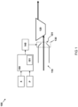
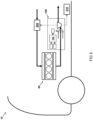
- FIG 1 illustrates an embodiment of a variable geometry turbine, VGT 100, e.g. suitable for automotive applications wherein the VGT is arranged in the exhaust system of an internal combustion engine, such as a diesel or spark ignition engine.
- the VGT 100 can for example be part of a mechanical turbocharger, to convert energy recovered from exhaust gases into boost pressure.
- the VGT 100 can for example be used for driving an electric compressor or for driving an electric generator, to convert energy recovered from exhaust gases into electric power, which can e.g. be stored in an electric power source or can be applied directly, to power other components.
- the VGT 100 comprises an intake channel 110, arranged for receiving a mass flow of exhaust gas from an internal combustion engine.
- the VGT 100 may comprise multiple intake channels 110, each arranged for receiving a mass flow of exhaust gas from the internal combustion engine.
- the intake channel 110 can comprise one or more exhaust gas entry ports, each of which is fluidly connected to one or more exhaust manifolds, which, in turn, are arranged for collecting exhaust gas discharged through exhaust ports on the cylinders of the internal combustion engine.
- the VGT 100 further comprises a rotor 120, arranged downstream the intake channel 110 for extracting energy from the mass flow of exhaust gas received from the intake channel 110.
- the rotor for example comprises blades for converting kinetic and potential energy in the mass flow of exhaust gas into torque to propel a rotor shaft of the VGT, e.g. to power a compressor or an electric generator.
- the rotor 120 can e.g. be a radial variant, arranged for receiving a mass flow of exhaust gas from a radial direction and discharging the mass flow in an axial direction.
- the rotor 120 can e.g. be an axial variant, arranged for receiving a mass flow of exhaust gas from an axial direction and discharging the mass flow in a radial direction.
- the VGT 100 comprises an adjustable nozzle 130, comprising a nozzle orifice 131 having an adjustable cross sectional area.
- the adjustable nozzle 130 is arranged for adjusting the mass flow of exhaust gas from the intake channel 110 to the rotor 120.
- the adjustable nozzle 130 can e.g. comprise sliding or pivoting vane elements, arranged for narrowing or widening the cross sectional area, in dependence of operating conditions of the VGT.
- the adjustable nozzle 130 is adjustable between an open position, in which the nozzle orifice 131 has a maximum cross sectional area, and a closed position, in which the nozzle orifice 131 has a minimum cross sectional area.
- the VGT 100 further comprises a nozzle actuator 140, arranged for actuating the adjustable nozzle 130 between the open position and the closed position.
- the VGT 100 may additionally comprise a transmission mechanism arranged for providing a mechanical transmission, e.g. comprising a linkage or a drive train, between the nozzle actuator 140 and the adjustable nozzle 130.
- the nozzle actuator 140 can be coupled directly to the adjustable nozzle 130.
- the nozzle actuator 140 can e.g. be a pneumatic actuator, arranged for using a gas, such as air, to actuate the adjustable nozzle 130, e.g. via a transmission mechanism.
- the nozzle actuator 140 can e.g.
- the nozzle actuator 140 can e.g. be an electric actuator. Any combinations of the above described types of nozzle actuator 140 may also be suitable for actuating the adjustable nozzle 130, e.g. by using a transmission mechanism.
- the VGT 100 further comprises a controller 150.
- the controller 150 can for example be a processor on board of the VGT.
- the controller 150 can e.g. be part of a central processing unit or an engine control unit, and communicatively coupled with elements of the VGT.
- the controller 150 is arranged for controlling the nozzle actuator 140 based on a nozzle position demand, e.g. a nozzle position between the open and closed position, for example based on operating conditions of the VGT such as the pressure upstream and/or downstream the turbine, rotor speed, or power output.
- the position of the adjustable nozzle 130 at which a VGT is most sensitive to pressure effects in the exhaust system e.g. a deflection point position of the adjustable nozzle at which a sharp difference in pre-turbine pressure upstream the VGT occurs, may vary between individual VGTs.
- a mean deflection point position can be considered, and a safety margin can be implemented to account for variations between VGTs.
- VGTs may be unnecessarily limited, thereby reducing the effectiveness of these VGTs, especially in the low exhaust mass flow region, where the benefits of improved fuel efficiency and reduced emission of harmful exhaust gases are most likely to be obtained.
- the controller 150 is provided with a calibration routine 151, arranged for calibrating the VGT 100 during normal operation thereof, e.g. during an on-line calibration procedure.
- the controller 150 runs the calibration routine 151 to calibrate the VGT 100, e.g. in dependence of operating conditions of an internal combustion engine powering the commercial vehicle. Because of varying operating conditions the mass flow of exhaust gas supplied to the intake channel 110 of the VGT 100 may change, e.g. in quantity or in pressure.
- the VGT 100 may need to be calibrated accordingly, by the calibration routine 151, to keep the VGT 100 in an optimal working range.
- the calibration routine 151 can e.g. be run during stationary operating condition, e.g. when the commercial vehicle is in idle condition. In this case, an internal combustion engine powering the vehicle may be run at a constant speed and/or load to calibrate the VGT across a broad spectrum of operating conditions.
- the calibration routine 151 can e.g. be arranged to determine the deflection point position during idle condition comprising specific engine modes and/or sensor values, such as a condition in which an exhaust gas recirculation (EGR) valve is closed and a brake pressure valve is opened.
- EGR exhaust gas recirculation
- the pre-turbine pressure P upstream the turbine can be maximized while the pressure downstream the turbine is minimalized. Accordingly, the force reversal effect, which causes the sharp difference in the pre-turbine pressure P, can be induced by adjusting the adjustable nozzle 130 towards the deflection point position 155.
- the controller 150 is arranged for controlling the nozzle actuator 140 to adjust the adjustable nozzle 130 from an initial position towards the closed position.
- the initial position can be set to preference, e.g. to detect a deflection point position 155 over a larger range or to speed up the calibration routine 151.
- the cross sectional area can be between 20% and 50% of the maximum cross sectional area in the open position, e.g. 30% of the maximum cross sectional area.
- the adjustment speed at which the adjustable nozzle is adjusted from the initial position towards the closed position can be set to preference. In this way, the sensitivity of the calibration routine 151 can e.g. be increased or the time to perform the calibration routine 151 can be decreased.
- the adjustment speed can be between 1% and 10% of the maximum cross sectional area per second, e.g. 2% of the maximum cross sectional area per second.
- the initial position and the adjustment speed can be set, such that the expected time to perform the calibration routine 151, e.g. from the start of the calibration routine 151 until the detection of the deflection point position 155, is approximately 10 seconds.
- the calibration routine 151 can for example be performed after (re)assembling or replacing a turbine, or after a predefined time period since completing a previous calibration routine 151.
- the controller 150 monitors a pre-turbine pressure measured in the mass flow of exhaust gas upstream the VGT 100, e.g. in an exhaust manifold of an internal combustion engine supplying exhaust gas to the intake channel 110 of the VGT 100.
- the controller 150 can for example be arranged for logging the position X of the adjustable nozzle 130, e.g. by receiving position data from a sensor or encoder that measures the nozzle position X, such as a capacitive sensor, a hall sensor, an LVDT, an optical encoder, etc.
- the position X of the adjustable nozzle 130 can be derived from a status of the nozzle actuator 140.
- the position data obtained can for example be used for determining a zero reference value, e.g. a zero-position, to define the closed position of the adjustable nozzle 130.
- a change in position of the adjustable nozzle 130 from the zero reference value toward the open position can for example be logged in absolute distance units, such as in millimetres, measured from the closed position.
- the position of the adjustable nozzle 130 can for example be logged in relative units, such as a percentage between the closed and open position, e.g. measured from the closed position, with 0% being fully closed and 100% being fully opened.
- the controller 150 may e.g. be arranged for logging the position X of the adjustable nozzle 130 as a function of a first time t1.
- the controller 150 may e.g. further be arranged for logging the pre-turbine pressure P as a function of a second time t2, wherein the second time t2 is synchronized with the first time t1.
- the controller 150 can e.g. be arranged for logging the pre-turbine pressure P as a function of the position X of the adjustable nozzle 130.
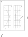
- the controller 150 is further arranged, in the calibration routine 151, for performing a step of detecting a deflection point position 155 of the adjustable nozzle at which a sharp difference in the pre-turbine pressure P occurs, as can be seen in FIG 2 .
- the controller 150 may detect a sharp, sudden difference in pre-turbine pressure P.
- the deflection point position 155 can for example be defined as the position of the adjustable nozzle 130 at which the sharp difference in pre-turbine pressure P starts, when moving the adjustable nozzle 130 from the open position to the closed position.
- the controller 150 is further arranged for adjusting the minimum cross sectional area in the closed position.
- the controller 150 can adjust a working range of the VGT 100, e.g. a range between the open position and the closed position, in dependence of varying operating conditions, such as pre-turbine pressure, rotor speed, power output, etc.
- the working range excludes the above described detected deflection point position 155, e.g.
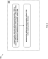
- FIG 3 illustrates another or further embodiment of the VGT 100.
- the controller 150 is arranged for comparing the detected deflection point position 155 to a stored deflection point position 157 of a pre-calibrated VGT, to determine a deflection point position offset 159.
- the deflection point position offset can e.g. be determined by performing the calibration routine 151 during idle conditions of the vehicle.
- the stored deflection point position 157 comprises one entry, associated with a position of the adjustable nozzle at which a sharp difference in the pre-turbine pressure P occurs.
- the stored deflection point can comprise more than one entry, wherein each entry is associated with a specific operating condition of the VGT and/or of the internal combustion engine, e.g. to represent different nozzle positions at which a sharp difference in pre-turbine pressure P can occur, depending on the respective operating condition.
- the entries can for example be stored in a memory accessible by the controller 150, such as from a lookup table.
- the controller 150 can be arranged for applying the deflection point position offset 159 to the nozzle position demand. In this way the working range of the VGT 100 can virtually be shifted away from the detected deflection point position 155. This can be used to effectively align the deflection points of individual VGTs, reducing the need for a safety margin in the calibration process.
- the controller 150 is arranged for detecting the deflection point position 155 by monitoring a second derivative of a filtered pre-turbine pressure sensor signal.
- Filtering and/or determining the second derivative of the sensor signal can e.g. be performed by the controller 150, or can be performed by another processing unit, such as an engine control unit or sensor processor.
- the calibration routine 151 can be made less sensitive to high frequency effects e.g. caused by dynamic behaviour of components and/or measurement errors.
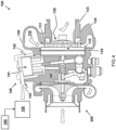
- FIG 4 illustrates another or further embodiment of the VGT 100, e.g. as part of a turbocharger, wherein the VGT 100 is arranged for driving a compressor 200.
- the adjustable nozzle 130 comprises vanes 134 disposed around a circumference of the rotor 120.
- the vanes may have a flow guiding surface that is arranged for guiding the mass flow of exhaust gas from the intake channel 110 to the rotor 120, e.g. in a tangential direction.
- the vanes 134 can e.g.
- a slidable tube 133 may be coaxially aligned with the rotor 120.
- the slidable tube 133 may be slidable around the vanes 134, e.g. along a direction parallel to the axis of rotation of the rotor 120, to adjust the flow guiding surface of the vanes 134.
- the slidable tube 133 may comprise an edge 135 which is slidable towards an opposing wall of the intake channel 120, thereby adjusting the cross sectional area of the nozzle orifice 131, e.g. to open or close the intake channel 120.
- the nozzle orifice 131 for example is formed by a gap between the slidable tube 133 and an opposing wall of the intake channel 110.
- the nozzle actuator 140 can for example be arranged for actuating the slidable tube 133, e.g. by translating the slidable element 133 against the opposing wall.
- the slidable tube 133 can for example be a cylindrical tube that is coaxially aligned with the rotor 120, with a tube wall that is arranged perpendicular to a direction of the mass flow of exhaust gas from the intake channel. Accordingly, when the nozzle actuator 140 e.g. translates the cylindrical tube to close the intake channel 110, the tube wall reduces the cross sectional area of the nozzle orifice 131.
- the edge 135 is near the opposing wall of the intake channel 120. Accordingly, a venturi is formed and the pressure in the mass flow of exhaust gas flowing through the adjustable nozzle is decreased. As a result, the slidable tube 133 is sucked towards the opposing wall of the intake channel and the cross sectional area of the nozzle orifice is further reduced, which may cause a significant decrease in mass flow and a build up of pressure in the exhaust line upstream the VGT 100.
- the calibration routine as described herein to detect the deflection point position, the working range of the VGT 100 can be adjusted to avoid the above described situation.
- the adjustable nozzle may comprise pivotable vanes, that are pivotable around an axis which is parallel to the axis of rotation of the rotor.
- the nozzle actuator can be arranged for actuating, e.g. rotating, the vanes.
- the nozzle actuator 140 shown here is a pneumatic actuator, comprising a piston 141, movable inside a piston chamber 142 and arranged for actuating the adjustable nozzle 130, via an actuation mechanism 148 comprising linkages.
- the piston chamber 142 can e.g. comprise a pressure inlet 143, e.g. arranged for receiving gas, such as air at a controlled pressure.
- the pneumatic actuator may further comprise a biasing element 144, such as a spring or diaphragm, mounted between the piston 141 and the piston chamber 142 and arranged for biasing the adjustable nozzle 130, e.g. towards the open or closed position.
- the actuator may further comprise a pressure generator 145, fluidly connected to the pressure inlet 143 and arranged for generating a pressure inside the piston chamber 142 to move the piston 141 by counteracting against the biasing element 144.
- the pressure generator can e.g. be a vacuum pump controlled by the controller 150 to generate a vacuum inside the piston chamber 142.
- the nozzle actuator 140 can be an hydraulic actuator, arranged for actuating the adjustable nozzle 130 using a pressurized fluid, such as water or oil.
- the nozzle actuator 140 can be an electric actuator, e.g. comprising an electric motor, e.g. a DC motor or a solenoid, optionally coupled to a transmission, to actuate the adjustable nozzle 130.
- the controller 150 is arranged for controlling the pneumatic actuator to adjust an actuation pressure based on the measured pre-turbine pressure P.
- the controller 150 may be arranged for controlling the pressure generator 145, such as a vacuum pump, to provide a stronger vacuum to actuate the adjustable nozzle 130.
- the intake channel 110 is arranged for providing the mass flow of exhaust gas to the rotor 120 in a direction substantially perpendicular to an axis of rotation of the rotor 120.
- the rotor 120 can be used as a radial variant.
- the intake channel 110 may be arranged for providing the mass flow of exhaust gas in a direction substantially parallel to the axis of rotation of the rotor 120.
- the intake channel 110 may be formed as a volute that is coaxially aligned with the rotor 120.
- the rotor 120 can be a radial variant and the intake channel can be formed as a volute, e.g. a curved funnel, with a center of curvature that is coaxially aligned with the axis of rotation of the rotor 120.
- the radius of curvature of the volute may e.g. decrease tangentially towards the rotor 120 to narrow the cross sectional area of the intake channel 110 along the direction of the flow, thereby accelerating the mass flow of exhaust gas fed to the rotor 120.
- a commercial vehicle 10 e.g. a truck or a bus, comprising a VGT 100 as described herein.
- the VGT 100 can for example be arranged in the exhaust system of the internal combustion engine 80 powering the commercial vehicle, such as a diesel or spark ignition engine.
- the VGT 100 can for example be part of a turbocharger, wherein the VGT 100 e.g. mechanically powers a compressor 200, to convert energy recovered from exhaust gases into boost pressure.
- FIG 6 provides a schematic representation of a method 1000 for calibrating a VGT 100, e.g. arranged in an exhaust system of an internal combustion engine.
- the VGT 100 comprises an intake channel 110, a rotor 120, and an adjustable nozzle 130.
- the intake channel 110 is arranged for receiving a mass flow of exhaust gas from the internal combustion engine.
- the rotor 120 is arranged downstream the intake channel 110 for extracting energy from the mass flow of exhaust gas.
- the adjustable nozzle 130 comprises a nozzle throat 131 having an adjustable cross sectional area 132 arranged for adjusting the mass flow of exhaust gas from the intake channel 110 to the rotor 120, wherein the adjustable nozzle 130 is adjustable between an open position, in which the nozzle throat 131 has a maximum cross sectional area 132-1, and a closed position, in which the nozzle throat 131 has a minimum cross sectional area 132-2.
- the method 1000 comprises step 1001 of adjusting the adjustable nozzle 130 from an initial position towards the closed position, while monitoring a pre-turbine pressure P measured upstream the VGT 100.
- the adjustable nozzle 130 can for example be adjusted manually or by an actuator, while the position of the adjustable nozzle is logged, e.g. as a function of time.
- the pre-turbine pressure P can for example be measured by a pressure sensor, e.g. arranged in an exhaust manifold or in an exhaust line between the internal combustion engine and the VGT 100.
- the measured pre-turbine pressure P can e.g. be logged as a function of time.
- the method 1000 further comprises step 1002 of detecting a deflection point position 155 of the adjustable nozzle 130 at which a sharp difference in the pre-turbine pressure P occurs.
- the deflection point position 155 can for example be detected visually, by comparing the time-logged nozzle position and pre-turbine pressure, or can be detected computationally, e.g. by comparing a derivative of the pre-turbine pressure against a threshold value.
- the deflection point position 155 can be defined when a first or second derivative of the pre-turbine pressure exceeds a threshold value.
- Step 1003 of the method 1000 comprises adjusting the minimum cross sectional area 132-2 in the closed position, to adjust a working range of the VGT 100 in dependence of varying operating conditions, wherein the working range excludes the detected deflection point position 155.
- variable geometry turbine is used for improved energy efficiency
- other technical, agricultural or industrial applications where a variable geometry turbine is used.
- the invention is not limited to any embodiment herein described and that modifications are possible which may be considered within the scope of the appended claims. Also kinematic inversions are considered inherently disclosed and can be within the scope of the invention. In the claims, any reference signs shall not be construed as limiting the claim.
Landscapes
- Engineering & Computer Science (AREA)
- Mechanical Engineering (AREA)
- General Engineering & Computer Science (AREA)
- Chemical & Material Sciences (AREA)
- Combustion & Propulsion (AREA)
- Physics & Mathematics (AREA)
- Geometry (AREA)
- Fluid Mechanics (AREA)
- Chemical Kinetics & Catalysis (AREA)
- General Chemical & Material Sciences (AREA)
- Supercharger (AREA)
- Control Of Turbines (AREA)
Abstract
- adjusting the adjustable nozzle from an initial position towards a closed position, while monitoring a pre-turbine pressure;
- detecting a deflection point position of the adjustable nozzle at which a sharp difference in the pre-turbine pressure occurs; and
- adjusting a minimum cross sectional area in the closed position, to adjust a working range of the VGT in dependence of varying operating conditions, wherein the working range excludes the detected deflection point position.
Description
- The invention relates to a variable geometry turbine and to a method for calibrating a variable geometry turbine.
- Variable geometry turbines (VGT) can be employed in various applications, such as in commercial vehicles, e.g. to improve the energy efficiency of an internal combustion engine driving such a vehicle. The VGT can extract residual energy from the exhaust gas produced by the engine, which can in turn e.g. be used for powering other components in the vehicle, such as a compressor By improving the energy efficiency, the internal combustion engine and corresponding power train can be downsized without a net reduction in output power. As such, proper implementation of a variable geometry turbine can also lead to improved fuel efficiency and reduced emission of harmful exhaust gases, such as NOx and CO2.
- VGTs typically comprise an adjustable nozzle to regulate the mass flow of exhaust gas to the rotor. At low exhaust mass flows, the adjustable nozzle may for example be narrowed, to adjust the aspect ratio of the turbine by accelerating the mass flow to the rotor. However, by narrowing the adjustable nozzle it forms a venturi, reducing the pressure in the exhaust gas as it passes through the adjustable nozzle. As a result, a suction force is applied between the walls of the thus formed venturi, which may cause the adjustable nozzle to narrow further, thereby effectively closing the VGT and restricting the mass flow significantly. This would, in turn, result in a sharp increase in pre-turbine pressure, which can significantly affect the pumping losses of the engine. To avoid the influence of pressure effects in the low mass flow region, the configuration of a VGT can be adjusted to the properties of the internal combustion engine and exhaust system. Due to part-to-part variations between individual VGTs, however, this means that a significant margin may be used to reduce the sensitivity of VGTs to these pressure effects during use, e.g. due to changing operating conditions or wear of the VGT, engine, or exhaust system. As a consequence of the margin, it may not be possible to utilize the full working range of the VGT, and as such the internal combustion engine may not achieve optimal performance and emissions.
- An object of the present invention is to improve the effectiveness of variable geometry turbines, by adjusting their working range based on operating conditions.
- In summary, the invention provides a variable geometry turbine (VGT), comprising an intake channel, a rotor, an adjustable nozzle, a nozzle actuator and a controller. The intake channel is arranged for receiving a mass flow of exhaust gas from an internal combustion engine. The rotor is arranged downstream the intake channel for extracting energy from the mass flow of exhaust gas. The adjustable nozzle comprises a nozzle orifice having an adjustable cross sectional area and arranged for adjusting the mass flow of exhaust gas from the intake channel to the rotor. The adjustable nozzle is adjustable between an open position, in which the nozzle orifice has a maximum cross sectional area, and a closed position, in which the nozzle orifice has a minimum cross sectional area. The nozzle actuator is arranged for actuating the adjustable nozzle between the open position and the closed position, and the controller is arranged for controlling the nozzle actuator based on a nozzle position demand. The controller comprises a calibration routine, arranged for calibrating the VGT during normal operation thereof. In the calibration routine, the controller is arranged for performing the steps of: adjusting the adjustable nozzle from an initial position towards the closed position, while monitoring a pre-turbine pressure measured in the mass flow of exhaust gas upstream the VGT; detecting a deflection point position of the adjustable nozzle at which a sharp difference in the pre-turbine pressure occurs; and adjusting a working range of the nozzle actuator , wherein the minimum cross sectional area in the closed position excludes the detected deflection point position.
- Accordingly, the working range of the VGT can be maximized during use, regardless of varying operating conditions, to utilize low exhaust mass flow regions while being less sensitive to the influence of pressure effects in these regions, thereby creating a more predictable exhaust mass flow. By detecting and excluding the deflection point position from the working range, any margin between the deflection point position and the working range of the VGT can be minimized. In this way, performance of the engine can be increased and the emission of harmful exhaust gases, such as NOx, can be reduced.
- In some embodiments, the controller is arranged for comparing the detected deflection point position to a stored deflection point position of a pre-calibrated VGT, to determine a deflection point position offset, as a difference between the detected deflection point position and the stored deflection point position. The controller can be arranged for applying the deflection point position offset to the nozzle position demand, so that the difference is applied as a trim to the VGT position demand. This distinguishes from a conventional generic, or average safety margin that can be implemented to cover a large distribution of errors and tolerances between individual VGTs, engines, exhaust systems, and other system components. In contrast, by the applied offset the working range of individual VGTs can be increased, because the safety margin accounting for these variations can be reduced. By determining a deflection point position offset, the working range of an individual VGT can be adjusted with respect to its own respective deflection point position, to avoid the occurrence of the sharp difference in the pre-turbine pressure, without having to implement an average safety margin. In statistical terms this means that the standard deviation between VGTs can be reduced, making it possible to calibrate the mean closer to the optimal deflection point position.
- To reduce the effect of measurement errors and dynamic behaviour of components on the detected deflection point position, the controller can be arranged for detecting the deflection point position by monitoring a second derivative of a filtered pre-turbine pressure sensor signal. The second derivative reaches its maximum precisely when there is a strong deviation from a smooth characteristic, which can be used to detect the deflection point position.
- The present invention is applicable to various types of actuators, such as hydraulic, pneumatic or electric actuators. As such the VGT is compatible with the most common designs of actuators. Preferably, the controller is arranged for controlling the nozzle actuator to adjust the adjustable nozzle based on the measured pre-turbine pressure, to counteract external forces on the VGT.
- In some embodiments, the intake channel is arranged for providing the mass flow of exhaust gas to the rotor in a direction substantially perpendicular to an axis of rotation of the rotor. As such, a radial variant of the rotor is provided, which receives the mass flow of exhaust gas from a radial direction and discharges the mass flow of exhaust gas in an axial direction. The present invention may however also be suitable for other variants of rotor designs, such as axial variants, in which the intake channel is arranged for providing the flow of exhaust gas to the rotor along the axis of rotation of the rotor.
- To increase the efficiency of the VGT and accelerate the mass flow of exhaust gas, the intake channel can be formed as a volute that is coaxially aligned with the rotor.
- In one embodiment, the adjustable nozzle comprises a slidable element. The element is slidable by the nozzle actuator to close the intake channel. Alternatively, the VGT may also be compatible with adjustable nozzle designs that comprise rotatable or pivotable vanes.
- Another aspect of the invention relates to a commercial vehicle, comprising a variable geometry turbine as described herein.
- Yet other aspects pertain to a method for calibrating a variable geometry turbine (VGT). The VGT comprises an intake channel, a rotor, and an adjustable nozzle. The intake channel is arranged for receiving a mass flow of exhaust gas from an internal combustion engine. The rotor is arranged downstream the intake channel for extracting energy from the mass flow of exhaust gas. The adjustable nozzle comprises a nozzle throat having an adjustable cross sectional area arranged for adjusting the mass flow of exhaust gas from the intake channel to the rotor, wherein the adjustable nozzle is adjustable between an open position, in which the nozzle throat has a maximum cross sectional area, and a closed position, in which the nozzle throat has a minimum cross sectional area. The method comprises the steps of: (i) adjusting the adjustable nozzle from an initial position towards the closed position, while monitoring a pre-turbine pressure measured upstream the VGT; (ii) detecting a deflection point position of the adjustable nozzle at which a sharp difference in the pre-turbine pressure occurs; and (iii) adjusting a working range of the nozzle actuator, having an adjusted minimum cross sectional area in the closed position that excludes the detected deflection point position .
- The invention will be further elucidated in the figures:
-
FIG 1 illustrates an embodiment of a VGT; -
FIG 2 provides an example of a deflection point position detected by the VGT; -
FIG 3 provides other or further embodiments of a controller of the VGT; -
FIG 4 illustrates another or further embodiment of the VGT; -
FIG 5 illustrates a commercial vehicle, comprising the VGT; -
FIG 6 represents a method for calibrating a VGT. - The invention is described more fully hereinafter with reference to the accompanying drawings, in which embodiments of the invention are shown. In the drawings, the absolute and relative sizes of systems, components, layers, and regions may be exaggerated for clarity. Embodiments may be described with reference to schematic and/or cross-section illustrations of possibly idealized embodiments and intermediate structures of the invention. In the description and drawings, like numbers refer to like elements throughout. Relative terms as well as derivatives thereof should be construed to refer to the orientation as then described or as shown in the drawing under discussion. These relative terms are for convenience of description and do not require that the system be constructed or operated in a particular orientation unless stated otherwise.
-
FIG 1 illustrates an embodiment of a variable geometry turbine,VGT 100, e.g. suitable for automotive applications wherein the VGT is arranged in the exhaust system of an internal combustion engine, such as a diesel or spark ignition engine. TheVGT 100 can for example be part of a mechanical turbocharger, to convert energy recovered from exhaust gases into boost pressure. Alternatively, theVGT 100 can for example be used for driving an electric compressor or for driving an electric generator, to convert energy recovered from exhaust gases into electric power, which can e.g. be stored in an electric power source or can be applied directly, to power other components. - The
VGT 100 comprises anintake channel 110, arranged for receiving a mass flow of exhaust gas from an internal combustion engine. TheVGT 100 may comprisemultiple intake channels 110, each arranged for receiving a mass flow of exhaust gas from the internal combustion engine. For example, theintake channel 110 can comprise one or more exhaust gas entry ports, each of which is fluidly connected to one or more exhaust manifolds, which, in turn, are arranged for collecting exhaust gas discharged through exhaust ports on the cylinders of the internal combustion engine. - The
VGT 100 further comprises arotor 120, arranged downstream theintake channel 110 for extracting energy from the mass flow of exhaust gas received from theintake channel 110. The rotor for example comprises blades for converting kinetic and potential energy in the mass flow of exhaust gas into torque to propel a rotor shaft of the VGT, e.g. to power a compressor or an electric generator. Therotor 120 can e.g. be a radial variant, arranged for receiving a mass flow of exhaust gas from a radial direction and discharging the mass flow in an axial direction. Alternatively, therotor 120 can e.g. be an axial variant, arranged for receiving a mass flow of exhaust gas from an axial direction and discharging the mass flow in a radial direction. - As illustrated in
FIG 1 , theVGT 100 comprises anadjustable nozzle 130, comprising anozzle orifice 131 having an adjustable cross sectional area. Theadjustable nozzle 130 is arranged for adjusting the mass flow of exhaust gas from theintake channel 110 to therotor 120. Theadjustable nozzle 130 can e.g. comprise sliding or pivoting vane elements, arranged for narrowing or widening the cross sectional area, in dependence of operating conditions of the VGT. Theadjustable nozzle 130 is adjustable between an open position, in which thenozzle orifice 131 has a maximum cross sectional area, and a closed position, in which thenozzle orifice 131 has a minimum cross sectional area. - The
VGT 100 further comprises anozzle actuator 140, arranged for actuating theadjustable nozzle 130 between the open position and the closed position. For example, theVGT 100 may additionally comprise a transmission mechanism arranged for providing a mechanical transmission, e.g. comprising a linkage or a drive train, between thenozzle actuator 140 and theadjustable nozzle 130. Alternatively, thenozzle actuator 140 can be coupled directly to theadjustable nozzle 130. Thenozzle actuator 140 can e.g. be a pneumatic actuator, arranged for using a gas, such as air, to actuate theadjustable nozzle 130, e.g. via a transmission mechanism. Alternatively, thenozzle actuator 140 can e.g. be an hydraulic actuator, arranged for using a fluid, such as water or an oil, for actuating theadjustable nozzle 130. Alternatively, thenozzle actuator 140 can e.g. be an electric actuator. Any combinations of the above described types ofnozzle actuator 140 may also be suitable for actuating theadjustable nozzle 130, e.g. by using a transmission mechanism. - The
VGT 100 further comprises acontroller 150. Thecontroller 150 can for example be a processor on board of the VGT. Alternatively, thecontroller 150 can e.g. be part of a central processing unit or an engine control unit, and communicatively coupled with elements of the VGT. Thecontroller 150 is arranged for controlling thenozzle actuator 140 based on a nozzle position demand, e.g. a nozzle position between the open and closed position, for example based on operating conditions of the VGT such as the pressure upstream and/or downstream the turbine, rotor speed, or power output. - There may be small variations in hardware between individual VGT's, e.g. due to manufacturing and assembly tolerances, deviations in mechanical parts and sensors, and/or wear and degradation of components. Accordingly, the position of the
adjustable nozzle 130 at which a VGT is most sensitive to pressure effects in the exhaust system, e.g. a deflection point position of the adjustable nozzle at which a sharp difference in pre-turbine pressure upstream the VGT occurs, may vary between individual VGTs. As a result, a mean deflection point position can be considered, and a safety margin can be implemented to account for variations between VGTs. However, this implies that the working range of some VGTs may be unnecessarily limited, thereby reducing the effectiveness of these VGTs, especially in the low exhaust mass flow region, where the benefits of improved fuel efficiency and reduced emission of harmful exhaust gases are most likely to be obtained. - Instead, according to the invention, to reduce the part-to-part spread between VGTs, and increase the working range of individual VGTs to improve their effectiveness, e.g. in the low exhaust mass flow region, the
controller 150 is provided with acalibration routine 151, arranged for calibrating theVGT 100 during normal operation thereof, e.g. during an on-line calibration procedure. For example, while theVGT 100 is in use, such as in a driven commercial vehicle, thecontroller 150 runs thecalibration routine 151 to calibrate theVGT 100, e.g. in dependence of operating conditions of an internal combustion engine powering the commercial vehicle. Because of varying operating conditions the mass flow of exhaust gas supplied to theintake channel 110 of theVGT 100 may change, e.g. in quantity or in pressure. As such, theVGT 100 may need to be calibrated accordingly, by thecalibration routine 151, to keep theVGT 100 in an optimal working range. Thecalibration routine 151 can e.g. be run during stationary operating condition, e.g. when the commercial vehicle is in idle condition. In this case, an internal combustion engine powering the vehicle may be run at a constant speed and/or load to calibrate the VGT across a broad spectrum of operating conditions. Thecalibration routine 151 can e.g. be arranged to determine the deflection point position during idle condition comprising specific engine modes and/or sensor values, such as a condition in which an exhaust gas recirculation (EGR) valve is closed and a brake pressure valve is opened. Under such conditions, the pre-turbine pressure P upstream the turbine can be maximized while the pressure downstream the turbine is minimalized. Accordingly, the force reversal effect, which causes the sharp difference in the pre-turbine pressure P, can be induced by adjusting theadjustable nozzle 130 towards thedeflection point position 155. - In the
calibration routine 151, thecontroller 150 is arranged for controlling thenozzle actuator 140 to adjust theadjustable nozzle 130 from an initial position towards the closed position. The initial position can be set to preference, e.g. to detect adeflection point position 155 over a larger range or to speed up thecalibration routine 151. For example, in the initial position the cross sectional area can be between 20% and 50% of the maximum cross sectional area in the open position, e.g. 30% of the maximum cross sectional area. Additionally, the adjustment speed at which the adjustable nozzle is adjusted from the initial position towards the closed position can be set to preference. In this way, the sensitivity of thecalibration routine 151 can e.g. be increased or the time to perform thecalibration routine 151 can be decreased. For example, the adjustment speed can be between 1% and 10% of the maximum cross sectional area per second, e.g. 2% of the maximum cross sectional area per second. For example, the initial position and the adjustment speed can be set, such that the expected time to perform thecalibration routine 151, e.g. from the start of thecalibration routine 151 until the detection of thedeflection point position 155, is approximately 10 seconds. Thecalibration routine 151 can for example be performed after (re)assembling or replacing a turbine, or after a predefined time period since completing aprevious calibration routine 151. - While adjusting the
adjustable nozzle 130, thecontroller 150 monitors a pre-turbine pressure measured in the mass flow of exhaust gas upstream theVGT 100, e.g. in an exhaust manifold of an internal combustion engine supplying exhaust gas to theintake channel 110 of theVGT 100. - As illustrated in
FIG 2 , thecontroller 150 can for example be arranged for logging the position X of theadjustable nozzle 130, e.g. by receiving position data from a sensor or encoder that measures the nozzle position X, such as a capacitive sensor, a hall sensor, an LVDT, an optical encoder, etc. Alternatively, the position X of theadjustable nozzle 130 can be derived from a status of thenozzle actuator 140. - The position data obtained can for example be used for determining a zero reference value, e.g. a zero-position, to define the closed position of the
adjustable nozzle 130. As such, a change in position of theadjustable nozzle 130 from the zero reference value toward the open position can for example be logged in absolute distance units, such as in millimetres, measured from the closed position. Alternatively, by additionally assigning a reference value to the open position, e.g. when the cross sectional area of the nozzle orifice is at a maximum, the position of theadjustable nozzle 130 can for example be logged in relative units, such as a percentage between the closed and open position, e.g. measured from the closed position, with 0% being fully closed and 100% being fully opened. - The
controller 150 may e.g. be arranged for logging the position X of theadjustable nozzle 130 as a function of a first time t1. Thecontroller 150 may e.g. further be arranged for logging the pre-turbine pressure P as a function of a second time t2, wherein the second time t2 is synchronized with the first time t1. Alternatively, or additionally, thecontroller 150 can e.g. be arranged for logging the pre-turbine pressure P as a function of the position X of theadjustable nozzle 130. - The
controller 150 is further arranged, in thecalibration routine 151, for performing a step of detecting adeflection point position 155 of the adjustable nozzle at which a sharp difference in the pre-turbine pressure P occurs, as can be seen inFIG 2 . For example, when monitoring the pre-turbine pressure P while adjusting theadjustable nozzle 130 between the open and closed position, thecontroller 150 may detect a sharp, sudden difference in pre-turbine pressure P. Thedeflection point position 155 can for example be defined as the position of theadjustable nozzle 130 at which the sharp difference in pre-turbine pressure P starts, when moving theadjustable nozzle 130 from the open position to the closed position. - In the
calibration routine 151, thecontroller 150 is further arranged for adjusting the minimum cross sectional area in the closed position. In this way thecontroller 150 can adjust a working range of theVGT 100, e.g. a range between the open position and the closed position, in dependence of varying operating conditions, such as pre-turbine pressure, rotor speed, power output, etc. The working range excludes the above described detecteddeflection point position 155, e.g. by (re)defining the closed position of theadjustable nozzle 130, such that the sharp difference in pre-turbine pressure does not occur when moving theadjustable nozzle 130 between the open position and the (re)defined closed position and yet the cross sectional area is minimized respective to the detected deflection point position, so that the minimal cross sectional area can be updated to a smaller value, which is yet sufficiently away from the deflection point position -
FIG 3 illustrates another or further embodiment of theVGT 100. Here, thecontroller 150 is arranged for comparing the detecteddeflection point position 155 to a storeddeflection point position 157 of a pre-calibrated VGT, to determine a deflection point position offset 159. The deflection point position offset can e.g. be determined by performing thecalibration routine 151 during idle conditions of the vehicle. In general, the storeddeflection point position 157 comprises one entry, associated with a position of the adjustable nozzle at which a sharp difference in the pre-turbine pressure P occurs. In some cases, however, the stored deflection point can comprise more than one entry, wherein each entry is associated with a specific operating condition of the VGT and/or of the internal combustion engine, e.g. to represent different nozzle positions at which a sharp difference in pre-turbine pressure P can occur, depending on the respective operating condition. The entries can for example be stored in a memory accessible by thecontroller 150, such as from a lookup table. - The
controller 150 can be arranged for applying the deflection point position offset 159 to the nozzle position demand. In this way the working range of theVGT 100 can virtually be shifted away from the detecteddeflection point position 155. This can be used to effectively align the deflection points of individual VGTs, reducing the need for a safety margin in the calibration process. - Preferably, the
controller 150 is arranged for detecting thedeflection point position 155 by monitoring a second derivative of a filtered pre-turbine pressure sensor signal. Filtering and/or determining the second derivative of the sensor signal can e.g. be performed by thecontroller 150, or can be performed by another processing unit, such as an engine control unit or sensor processor. By using the second derivative of a filtered signal, thecalibration routine 151 can be made less sensitive to high frequency effects e.g. caused by dynamic behaviour of components and/or measurement errors. -
FIG 4 illustrates another or further embodiment of theVGT 100, e.g. as part of a turbocharger, wherein theVGT 100 is arranged for driving acompressor 200. In some embodiments of theVGT 100, e.g. as can be seen inFIG 4 , theadjustable nozzle 130 comprisesvanes 134 disposed around a circumference of therotor 120. The vanes may have a flow guiding surface that is arranged for guiding the mass flow of exhaust gas from theintake channel 110 to therotor 120, e.g. in a tangential direction. Thevanes 134 can e.g. form a ring around therotor 120, and each vane can have a flow guiding surface that is oriented at an angle for guiding the mass flow of exhaust gas. Aslidable tube 133 may be coaxially aligned with therotor 120. Theslidable tube 133 may be slidable around thevanes 134, e.g. along a direction parallel to the axis of rotation of therotor 120, to adjust the flow guiding surface of thevanes 134. For example, theslidable tube 133 may comprise anedge 135 which is slidable towards an opposing wall of theintake channel 120, thereby adjusting the cross sectional area of thenozzle orifice 131, e.g. to open or close theintake channel 120. - The
nozzle orifice 131 for example is formed by a gap between theslidable tube 133 and an opposing wall of theintake channel 110. Thenozzle actuator 140 can for example be arranged for actuating theslidable tube 133, e.g. by translating theslidable element 133 against the opposing wall. Theslidable tube 133 can for example be a cylindrical tube that is coaxially aligned with therotor 120, with a tube wall that is arranged perpendicular to a direction of the mass flow of exhaust gas from the intake channel. Accordingly, when thenozzle actuator 140 e.g. translates the cylindrical tube to close theintake channel 110, the tube wall reduces the cross sectional area of thenozzle orifice 131. - Around the deflection point position described herein, the
edge 135 is near the opposing wall of theintake channel 120. Accordingly, a venturi is formed and the pressure in the mass flow of exhaust gas flowing through the adjustable nozzle is decreased. As a result, theslidable tube 133 is sucked towards the opposing wall of the intake channel and the cross sectional area of the nozzle orifice is further reduced, which may cause a significant decrease in mass flow and a build up of pressure in the exhaust line upstream theVGT 100. By performing the calibration routine as described herein to detect the deflection point position, the working range of theVGT 100 can be adjusted to avoid the above described situation. - Similar effects may occur in alternative embodiments, wherein the vanes are rotatable to adjust the cross sectional area of the nozzle orifice. For example, the adjustable nozzle may comprise pivotable vanes, that are pivotable around an axis which is parallel to the axis of rotation of the rotor. By pivoting, e.g. opening and closing, the vanes, the mass flow of exhaust gas to the rotor can be adjusted. The nozzle actuator can be arranged for actuating, e.g. rotating, the vanes. When the vanes are rotated such that the gaps between the vanes are relatively narrow, a venturi is formed and the pressure in the mass flow of exhaust gas flowing through the gaps is reduced. As a result, a suction-effect is created between the vanes, which may cause the vanes to rotate further towards a more closed position, thereby decreasing the mass flow and increasing the pre-turbine pressure. By performing the calibration routine, the deflection point position at which this phenomenon occurs can be detected, and the above described effect can be avoided.
- The
nozzle actuator 140 shown here is a pneumatic actuator, comprising apiston 141, movable inside apiston chamber 142 and arranged for actuating theadjustable nozzle 130, via anactuation mechanism 148 comprising linkages. Thepiston chamber 142 can e.g. comprise apressure inlet 143, e.g. arranged for receiving gas, such as air at a controlled pressure. The pneumatic actuator may further comprise abiasing element 144, such as a spring or diaphragm, mounted between thepiston 141 and thepiston chamber 142 and arranged for biasing theadjustable nozzle 130, e.g. towards the open or closed position. The actuator may further comprise apressure generator 145, fluidly connected to thepressure inlet 143 and arranged for generating a pressure inside thepiston chamber 142 to move thepiston 141 by counteracting against the biasingelement 144. The pressure generator can e.g. be a vacuum pump controlled by thecontroller 150 to generate a vacuum inside thepiston chamber 142. Alternatively, thenozzle actuator 140 can be an hydraulic actuator, arranged for actuating theadjustable nozzle 130 using a pressurized fluid, such as water or oil. Alternatively, thenozzle actuator 140 can be an electric actuator, e.g. comprising an electric motor, e.g. a DC motor or a solenoid, optionally coupled to a transmission, to actuate theadjustable nozzle 130. - Preferably, the
controller 150 is arranged for controlling the pneumatic actuator to adjust an actuation pressure based on the measured pre-turbine pressure P. For example, when the pre-turbine pressure is relatively high, thecontroller 150 may be arranged for controlling thepressure generator 145, such as a vacuum pump, to provide a stronger vacuum to actuate theadjustable nozzle 130. - In some embodiments of the
VGT 100, e.g. as shown inFIG 4 , theintake channel 110 is arranged for providing the mass flow of exhaust gas to therotor 120 in a direction substantially perpendicular to an axis of rotation of therotor 120. As such, therotor 120 can be used as a radial variant. Alternatively, when therotor 120 is an axial variant, theintake channel 110 may be arranged for providing the mass flow of exhaust gas in a direction substantially parallel to the axis of rotation of therotor 120. - The
intake channel 110 may be formed as a volute that is coaxially aligned with therotor 120. For example, therotor 120 can be a radial variant and the intake channel can be formed as a volute, e.g. a curved funnel, with a center of curvature that is coaxially aligned with the axis of rotation of therotor 120. The radius of curvature of the volute may e.g. decrease tangentially towards therotor 120 to narrow the cross sectional area of theintake channel 110 along the direction of the flow, thereby accelerating the mass flow of exhaust gas fed to therotor 120. - In
FIG 5 is illustrated acommercial vehicle 10, e.g. a truck or a bus, comprising aVGT 100 as described herein. TheVGT 100 can for example be arranged in the exhaust system of theinternal combustion engine 80 powering the commercial vehicle, such as a diesel or spark ignition engine. TheVGT 100 can for example be part of a turbocharger, wherein theVGT 100 e.g. mechanically powers acompressor 200, to convert energy recovered from exhaust gases into boost pressure. -
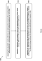
FIG 6 provides a schematic representation of amethod 1000 for calibrating aVGT 100, e.g. arranged in an exhaust system of an internal combustion engine. TheVGT 100 comprises anintake channel 110, arotor 120, and anadjustable nozzle 130. Theintake channel 110 is arranged for receiving a mass flow of exhaust gas from the internal combustion engine. Therotor 120 is arranged downstream theintake channel 110 for extracting energy from the mass flow of exhaust gas. Theadjustable nozzle 130 comprises anozzle throat 131 having an adjustable cross sectional area 132 arranged for adjusting the mass flow of exhaust gas from theintake channel 110 to therotor 120, wherein theadjustable nozzle 130 is adjustable between an open position, in which thenozzle throat 131 has a maximum cross sectional area 132-1, and a closed position, in which thenozzle throat 131 has a minimum cross sectional area 132-2. - As illustrated in
FIG 6 , themethod 1000 comprisesstep 1001 of adjusting theadjustable nozzle 130 from an initial position towards the closed position, while monitoring a pre-turbine pressure P measured upstream theVGT 100. Theadjustable nozzle 130 can for example be adjusted manually or by an actuator, while the position of the adjustable nozzle is logged, e.g. as a function of time. The pre-turbine pressure P can for example be measured by a pressure sensor, e.g. arranged in an exhaust manifold or in an exhaust line between the internal combustion engine and theVGT 100. The measured pre-turbine pressure P can e.g. be logged as a function of time. - The
method 1000 further comprisesstep 1002 of detecting adeflection point position 155 of theadjustable nozzle 130 at which a sharp difference in the pre-turbine pressure P occurs. Thedeflection point position 155 can for example be detected visually, by comparing the time-logged nozzle position and pre-turbine pressure, or can be detected computationally, e.g. by comparing a derivative of the pre-turbine pressure against a threshold value. For example, thedeflection point position 155 can be defined when a first or second derivative of the pre-turbine pressure exceeds a threshold value. -
Step 1003 of themethod 1000 comprises adjusting the minimum cross sectional area 132-2 in the closed position, to adjust a working range of theVGT 100 in dependence of varying operating conditions, wherein the working range excludes the detecteddeflection point position 155. - It is thus believed that the operation and construction of the present invention will be apparent from the foregoing description and drawings appended thereto. For the purpose of clarity and a concise description features are described herein as part of the same or separate embodiments, however, it will be appreciated that the scope of the invention may include embodiments having combinations of all or some of the features described.
- The invention applies not only to automotive applications where the variable geometry turbine is used for improved energy efficiency, but also to other technical, agricultural or industrial applications where a variable geometry turbine is used. It will be clear to the skilled person that the invention is not limited to any embodiment herein described and that modifications are possible which may be considered within the scope of the appended claims. Also kinematic inversions are considered inherently disclosed and can be within the scope of the invention. In the claims, any reference signs shall not be construed as limiting the claim.
- The terms 'comprising' and 'including' when used in this description or the appended claims should not be construed in an exclusive or exhaustive sense but rather in an inclusive sense. Thus expression as 'including' or 'comprising' as used herein does not exclude the presence of other elements, additional structure or additional acts or steps in addition to those listed. Furthermore, the words 'a' and 'an' shall not be construed as limited to 'only one', but instead are used to mean `at least one', and do not exclude a plurality. Features that are not specifically or explicitly described or claimed may additionally be included in the structure of the invention without departing from its scope.
- Expressions such as: "means for ..." should be read as: "component configured for ..." or "member constructed to ..." and should be construed to include equivalents for the structures disclosed. The use of expressions like: "critical", "preferred", "especially preferred" etc. is not intended to limit the invention. To the extent that structure, material, or acts are considered to be essential they are inexpressively indicated as such. Additions, deletions, and modifications within the purview of the skilled person may generally be made without departing from the scope of the invention, as determined by the claims.
Claims (11)
- A variable geometry turbine (VGT), comprising:- an intake channel, arranged for receiving a mass flow of exhaust gas from an internal combustion engine;- a rotor, arranged downstream the intake channel for extracting energy from the mass flow of exhaust gas;- an adjustable nozzle, comprising a nozzle orifice having an adjustable cross sectional area and arranged for adjusting the mass flow of exhaust gas from the intake channel to the rotor, wherein the adjustable nozzle is adjustable between an open position, in which the nozzle orifice has a maximum cross sectional area, and a closed position, in which the nozzle orifice has a minimum cross sectional area;- a nozzle actuator, arranged for actuating the adjustable nozzle between the open position and the closed position; and- a controller, arranged for controlling the nozzle actuator based on a nozzle position demand;wherein the controller comprises a calibration routine, arranged for calibrating the VGT during normal operation thereof;wherein, in the calibration routine, the controller is arranged for performing the steps of:- adjusting the adjustable nozzle from an initial position towards the closed position, while monitoring a pre-turbine pressure measured in the mass flow of exhaust gas upstream the VGT;- detecting a deflection point position of the adjustable nozzle at which a sharp difference in the pre-turbine pressure occurs; and- adjusting a working range of the nozzle actuator , having an adjusted minimum cross sectional area in the closed position that excludes the detected deflection point position.
- Variable geometry turbine according to claim 1, wherein the controller is arranged for comparing the detected deflection point position to a stored deflection point position of a pre-calibrated VGT, to determine a deflection point position offset, and wherein the controller is arranged for applying the deflection point position offset to the nozzle position demand.
- Variable geometry turbine according to any preceding claim, wherein the controller is arranged for detecting the deflection point position by monitoring a second derivative of a filtered pre-turbine pressure sensor signal.
- Variable geometry turbine according to any preceding claim, wherein the controller is arranged for controlling the nozzle actuator to adjust the adjustable nozzle based on the measured pre-turbine pressure.
- Variable geometry turbine according to any preceding claim, wherein the intake channel is arranged for providing the mass flow of exhaust gas to the rotor in a direction substantially perpendicular to an axis of rotation of the rotor.
- Variable geometry turbine according to any preceding claim, wherein the intake channel is formed as a volute that is coaxially aligned with the rotor.
- Variable geometry turbine according to any preceding claim, wherein the adjustable nozzle comprises vanes disposed around a circumference of the rotor.
- Variable geometry turbine according claim 7, wherein the vanes are rotatable to adjust the cross sectional area of the nozzle orifice, and wherein the nozzle actuator is arranged for actuating the vanes.
- Variable geometry turbine according to claim 7, further comprising a slidable cylinder which is slidable towards an opposing wall of the intake channel to adjust the cross sectional area of the nozzle orifice, and wherein the nozzle actuator is arranged for actuating the slidable cylinder.
- A commercial vehicle, comprising a variable geometry turbine according to any preceding claim.
- A method for calibrating a variable geometry turbine (VGT) comprising:- an intake channel, arranged for receiving a mass flow of exhaust gas from an internal combustion engine;- a rotor, arranged downstream the intake channel for extracting energy from the mass flow of exhaust gas;- an adjustable nozzle, comprising a nozzle throat having an adjustable cross sectional area arranged for adjusting the mass flow of exhaust gas from the intake channel to the rotor, wherein the adjustable nozzle is adjustable between an open position, in which the nozzle throat has a maximum cross sectional area, and a closed position, in which the nozzle throat has a minimum cross sectional area;wherein the method comprises the steps of:- adjusting the adjustable nozzle from an initial position towards the closed position, while monitoring a pre-turbine pressure measured upstream the VGT;- detecting a deflection point position of the adjustable nozzle at which a sharp difference in the pre-turbine pressure occurs; and- adjusting a working range of the nozzle actuator, having an adjusted minimum cross sectional area in the closed position that excludes the detected deflection point position .
Applications Claiming Priority (1)
| Application Number | Priority Date | Filing Date | Title |
|---|---|---|---|
| NL2031474A NL2031474B1 (en) | 2022-04-01 | 2022-04-01 | Variable geometry turbine and method for calibrating a variable geometry turbine |
Publications (3)
| Publication Number | Publication Date |
|---|---|
| EP4253741A1 true EP4253741A1 (en) | 2023-10-04 |
| EP4253741C0 EP4253741C0 (en) | 2024-11-20 |
| EP4253741B1 EP4253741B1 (en) | 2024-11-20 |
Family
ID=82594598
Family Applications (1)
| Application Number | Title | Priority Date | Filing Date |
|---|---|---|---|
| EP23165861.8A Active EP4253741B1 (en) | 2022-04-01 | 2023-03-31 | Variable geometry turbine and method for calibrating a variable geometry turbine |
Country Status (3)
| Country | Link |
|---|---|
| US (1) | US11898568B2 (en) |
| EP (1) | EP4253741B1 (en) |
| NL (1) | NL2031474B1 (en) |
Citations (4)
| Publication number | Priority date | Publication date | Assignee | Title |
|---|---|---|---|---|
| US20090123272A1 (en) * | 2007-11-13 | 2009-05-14 | Love Andrew C | Adaptive variable geometry turbocharger strategy |
| US20090299673A1 (en) * | 2008-05-29 | 2009-12-03 | Padhye Umesh V | Method of calibrating an actuator system for a variable nozzle of a turbocharger |
| US20140363278A1 (en) * | 2013-06-11 | 2014-12-11 | Deere & Company | Variable geometry turbocharger control system |
| US20160084155A1 (en) * | 2014-09-20 | 2016-03-24 | GM Global Technology Operations LLC | Turbocharger system |
Family Cites Families (4)
| Publication number | Priority date | Publication date | Assignee | Title |
|---|---|---|---|---|
| US8151567B2 (en) * | 2007-05-29 | 2012-04-10 | Ford Global Technologies, Llc | Adaptive learning system and method of vane position for a variable geometry turbocharger |
| US7593828B2 (en) * | 2007-08-16 | 2009-09-22 | Gm Global Technology Operations, Inc. | Method and apparatus for monitoring a variable geometry intake air compressor device |
| US9410475B2 (en) * | 2014-06-09 | 2016-08-09 | Ford Global Technologies, Llc | System and method for determining turbine degradation and mitigating turbine degradation in a variable geometry turbocharger |
| US10995684B1 (en) * | 2019-11-21 | 2021-05-04 | Internatinal Engine Intellectual Property Company, LLC. | Smart actuator learn command process |
-
2022
- 2022-04-01 NL NL2031474A patent/NL2031474B1/en active
-
2023
- 2023-03-13 US US18/120,668 patent/US11898568B2/en active Active
- 2023-03-31 EP EP23165861.8A patent/EP4253741B1/en active Active
Patent Citations (4)
| Publication number | Priority date | Publication date | Assignee | Title |
|---|---|---|---|---|
| US20090123272A1 (en) * | 2007-11-13 | 2009-05-14 | Love Andrew C | Adaptive variable geometry turbocharger strategy |
| US20090299673A1 (en) * | 2008-05-29 | 2009-12-03 | Padhye Umesh V | Method of calibrating an actuator system for a variable nozzle of a turbocharger |
| US20140363278A1 (en) * | 2013-06-11 | 2014-12-11 | Deere & Company | Variable geometry turbocharger control system |
| US20160084155A1 (en) * | 2014-09-20 | 2016-03-24 | GM Global Technology Operations LLC | Turbocharger system |
Also Published As
| Publication number | Publication date |
|---|---|
| NL2031474B1 (en) | 2023-10-24 |
| EP4253741C0 (en) | 2024-11-20 |
| US11898568B2 (en) | 2024-02-13 |
| EP4253741B1 (en) | 2024-11-20 |
| US20230313808A1 (en) | 2023-10-05 |
Similar Documents
| Publication | Publication Date | Title |
|---|---|---|
| US8210793B2 (en) | Radial flow compressor for a turbo-supercharger | |
| US8172516B2 (en) | Variable geometry turbine | |
| KR101619334B1 (en) | Vane travel adjustement screw | |
| US7628580B2 (en) | Variable geometry turbine | |
| CN1324222C (en) | Profile-changeable turbine | |
| CN1693679A (en) | A Method of Exhaust Gas Temperature Control for Diesel Engine Aftertreatment System Using Deformable Turbine | |
| US6739134B2 (en) | Exhaust gas turbocharger for an internal combustion engine | |
| CN109790758B (en) | Turbocharger for an internal combustion engine | |
| US8122716B2 (en) | VNT flow calibration adjustment | |
| US10036274B2 (en) | Variable pivot center VTG vanes and vane pack assembly | |
| US11898568B2 (en) | Variable geometry turbine and method for calibrating a variable geometry turbine | |
| US7305826B2 (en) | Axial loading management in turbomachinery | |
| CN113389650A (en) | Supercharging pressure control device for internal combustion engine | |
| WO2011108093A1 (en) | Control device for internal combustion engine having supercharger | |
| US20030115869A1 (en) | Variable geometry nozzle for radial turbines | |
| EP1876333B1 (en) | Variable vane type turbo charger control device | |
| JP3776707B2 (en) | Control device for variable capacity turbocharger | |
| US12163436B1 (en) | Guide blade for a guide device | |
| KR20010061233A (en) | Turbocharger engine | |
| CN110195618B (en) | Variable geometry turbine | |
| KR20200048889A (en) | Apparatus for controlling engine with variable geometry turbo-charger |
Legal Events
| Date | Code | Title | Description |
|---|---|---|---|
| PUAI | Public reference made under article 153(3) epc to a published international application that has entered the european phase |
Free format text: ORIGINAL CODE: 0009012 |
|
| STAA | Information on the status of an ep patent application or granted ep patent |
Free format text: STATUS: THE APPLICATION HAS BEEN PUBLISHED |
|
| AK | Designated contracting states |
Kind code of ref document: A1 Designated state(s): AL AT BE BG CH CY CZ DE DK EE ES FI FR GB GR HR HU IE IS IT LI LT LU LV MC ME MK MT NL NO PL PT RO RS SE SI SK SM TR |
|
| STAA | Information on the status of an ep patent application or granted ep patent |
Free format text: STATUS: REQUEST FOR EXAMINATION WAS MADE |
|
| 17P | Request for examination filed |
Effective date: 20240214 |
|
| RBV | Designated contracting states (corrected) |
Designated state(s): AL AT BE BG CH CY CZ DE DK EE ES FI FR GB GR HR HU IE IS IT LI LT LU LV MC ME MK MT NL NO PL PT RO RS SE SI SK SM TR |
|
| GRAP | Despatch of communication of intention to grant a patent |
Free format text: ORIGINAL CODE: EPIDOSNIGR1 |
|
| STAA | Information on the status of an ep patent application or granted ep patent |
Free format text: STATUS: GRANT OF PATENT IS INTENDED |
|
| RIC1 | Information provided on ipc code assigned before grant |
Ipc: F02B 37/24 20060101ALI20240529BHEP Ipc: F02C 9/22 20060101ALI20240529BHEP Ipc: F02C 6/12 20060101AFI20240529BHEP |
|
| INTG | Intention to grant announced |
Effective date: 20240618 |
|
| GRAS | Grant fee paid |
Free format text: ORIGINAL CODE: EPIDOSNIGR3 |
|
| GRAA | (expected) grant |
Free format text: ORIGINAL CODE: 0009210 |
|
| STAA | Information on the status of an ep patent application or granted ep patent |
Free format text: STATUS: THE PATENT HAS BEEN GRANTED |
|
| AK | Designated contracting states |
Kind code of ref document: B1 Designated state(s): AL AT BE BG CH CY CZ DE DK EE ES FI FR GB GR HR HU IE IS IT LI LT LU LV MC ME MK MT NL NO PL PT RO RS SE SI SK SM TR |
|
| REG | Reference to a national code |
Ref country code: GB Ref legal event code: FG4D |
|
| REG | Reference to a national code |
Ref country code: CH Ref legal event code: EP |
|
| REG | Reference to a national code |
Ref country code: DE Ref legal event code: R096 Ref document number: 602023001061 Country of ref document: DE |
|
| REG | Reference to a national code |
Ref country code: IE Ref legal event code: FG4D |
|
| U01 | Request for unitary effect filed |
Effective date: 20241203 |
|
| U07 | Unitary effect registered |
Designated state(s): AT BE BG DE DK EE FI FR IT LT LU LV MT NL PT RO SE SI Effective date: 20241212 |
|
| U20 | Renewal fee for the european patent with unitary effect paid |
Year of fee payment: 3 Effective date: 20250211 |
|
| PG25 | Lapsed in a contracting state [announced via postgrant information from national office to epo] |
Ref country code: IS Free format text: LAPSE BECAUSE OF FAILURE TO SUBMIT A TRANSLATION OF THE DESCRIPTION OR TO PAY THE FEE WITHIN THE PRESCRIBED TIME-LIMIT Effective date: 20250320 Ref country code: HR Free format text: LAPSE BECAUSE OF FAILURE TO SUBMIT A TRANSLATION OF THE DESCRIPTION OR TO PAY THE FEE WITHIN THE PRESCRIBED TIME-LIMIT Effective date: 20241120 |
|
| PG25 | Lapsed in a contracting state [announced via postgrant information from national office to epo] |
Ref country code: ES Free format text: LAPSE BECAUSE OF FAILURE TO SUBMIT A TRANSLATION OF THE DESCRIPTION OR TO PAY THE FEE WITHIN THE PRESCRIBED TIME-LIMIT Effective date: 20241120 |
|
| PG25 | Lapsed in a contracting state [announced via postgrant information from national office to epo] |
Ref country code: NO Free format text: LAPSE BECAUSE OF FAILURE TO SUBMIT A TRANSLATION OF THE DESCRIPTION OR TO PAY THE FEE WITHIN THE PRESCRIBED TIME-LIMIT Effective date: 20250220 |
|
| PG25 | Lapsed in a contracting state [announced via postgrant information from national office to epo] |
Ref country code: GR Free format text: LAPSE BECAUSE OF FAILURE TO SUBMIT A TRANSLATION OF THE DESCRIPTION OR TO PAY THE FEE WITHIN THE PRESCRIBED TIME-LIMIT Effective date: 20250221 |
|
| PG25 | Lapsed in a contracting state [announced via postgrant information from national office to epo] |
Ref country code: PL Free format text: LAPSE BECAUSE OF FAILURE TO SUBMIT A TRANSLATION OF THE DESCRIPTION OR TO PAY THE FEE WITHIN THE PRESCRIBED TIME-LIMIT Effective date: 20241120 |
|
| PG25 | Lapsed in a contracting state [announced via postgrant information from national office to epo] |
Ref country code: RS Free format text: LAPSE BECAUSE OF FAILURE TO SUBMIT A TRANSLATION OF THE DESCRIPTION OR TO PAY THE FEE WITHIN THE PRESCRIBED TIME-LIMIT Effective date: 20250220 |
|
| PG25 | Lapsed in a contracting state [announced via postgrant information from national office to epo] |
Ref country code: SM Free format text: LAPSE BECAUSE OF FAILURE TO SUBMIT A TRANSLATION OF THE DESCRIPTION OR TO PAY THE FEE WITHIN THE PRESCRIBED TIME-LIMIT Effective date: 20241120 |
|
| PG25 | Lapsed in a contracting state [announced via postgrant information from national office to epo] |
Ref country code: SK Free format text: LAPSE BECAUSE OF FAILURE TO SUBMIT A TRANSLATION OF THE DESCRIPTION OR TO PAY THE FEE WITHIN THE PRESCRIBED TIME-LIMIT Effective date: 20241120 |
|
| PG25 | Lapsed in a contracting state [announced via postgrant information from national office to epo] |
Ref country code: CZ Free format text: LAPSE BECAUSE OF FAILURE TO SUBMIT A TRANSLATION OF THE DESCRIPTION OR TO PAY THE FEE WITHIN THE PRESCRIBED TIME-LIMIT Effective date: 20241120 |
|
| PLBE | No opposition filed within time limit |
Free format text: ORIGINAL CODE: 0009261 |
|
| STAA | Information on the status of an ep patent application or granted ep patent |
Free format text: STATUS: NO OPPOSITION FILED WITHIN TIME LIMIT |
|
| PG25 | Lapsed in a contracting state [announced via postgrant information from national office to epo] |
Ref country code: MC Free format text: LAPSE BECAUSE OF FAILURE TO SUBMIT A TRANSLATION OF THE DESCRIPTION OR TO PAY THE FEE WITHIN THE PRESCRIBED TIME-LIMIT Effective date: 20241120 |
|
| 26N | No opposition filed |
Effective date: 20250821 |
|
| PG25 | Lapsed in a contracting state [announced via postgrant information from national office to epo] |
Ref country code: IE Free format text: LAPSE BECAUSE OF NON-PAYMENT OF DUE FEES Effective date: 20250331 |
|
| U20 | Renewal fee for the european patent with unitary effect paid |
Year of fee payment: 4 Effective date: 20260326 |
|
| PG25 | Lapsed in a contracting state [announced via postgrant information from national office to epo] |
Ref country code: CY Free format text: LAPSE BECAUSE OF FAILURE TO SUBMIT A TRANSLATION OF THE DESCRIPTION OR TO PAY THE FEE WITHIN THE PRESCRIBED TIME-LIMIT Effective date: 20241120 |