EP4253732A1 - System and method for aligning a casing wall of a turbomachine - Google Patents
System and method for aligning a casing wall of a turbomachine Download PDFInfo
- Publication number
- EP4253732A1 EP4253732A1 EP23161154.2A EP23161154A EP4253732A1 EP 4253732 A1 EP4253732 A1 EP 4253732A1 EP 23161154 A EP23161154 A EP 23161154A EP 4253732 A1 EP4253732 A1 EP 4253732A1
- Authority
- EP
- European Patent Office
- Prior art keywords
- wall
- alignment
- casing
- lip
- disposed
- Prior art date
- Legal status (The legal status is an assumption and is not a legal conclusion. Google has not performed a legal analysis and makes no representation as to the accuracy of the status listed.)
- Granted
Links
Images



Classifications
-
- F—MECHANICAL ENGINEERING; LIGHTING; HEATING; WEAPONS; BLASTING
- F01—MACHINES OR ENGINES IN GENERAL; ENGINE PLANTS IN GENERAL; STEAM ENGINES
- F01D—NON-POSITIVE DISPLACEMENT MACHINES OR ENGINES, e.g. STEAM TURBINES
- F01D25/00—Component parts, details, or accessories, not provided for in, or of interest apart from, other groups
- F01D25/24—Casings; Casing parts, e.g. diaphragms, casing fastenings
- F01D25/26—Double casings; Measures against temperature strain in casings
-
- F—MECHANICAL ENGINEERING; LIGHTING; HEATING; WEAPONS; BLASTING
- F01—MACHINES OR ENGINES IN GENERAL; ENGINE PLANTS IN GENERAL; STEAM ENGINES
- F01D—NON-POSITIVE DISPLACEMENT MACHINES OR ENGINES, e.g. STEAM TURBINES
- F01D25/00—Component parts, details, or accessories, not provided for in, or of interest apart from, other groups
- F01D25/24—Casings; Casing parts, e.g. diaphragms, casing fastenings
- F01D25/243—Flange connections; Bolting arrangements
-
- F—MECHANICAL ENGINEERING; LIGHTING; HEATING; WEAPONS; BLASTING
- F01—MACHINES OR ENGINES IN GENERAL; ENGINE PLANTS IN GENERAL; STEAM ENGINES
- F01D—NON-POSITIVE DISPLACEMENT MACHINES OR ENGINES, e.g. STEAM TURBINES
- F01D25/00—Component parts, details, or accessories, not provided for in, or of interest apart from, other groups
- F01D25/28—Supporting or mounting arrangements, e.g. for turbine casing
-
- F—MECHANICAL ENGINEERING; LIGHTING; HEATING; WEAPONS; BLASTING
- F05—INDEXING SCHEMES RELATING TO ENGINES OR PUMPS IN VARIOUS SUBCLASSES OF CLASSES F01-F04
- F05D—INDEXING SCHEME FOR ASPECTS RELATING TO NON-POSITIVE-DISPLACEMENT MACHINES OR ENGINES, GAS-TURBINES OR JET-PROPULSION PLANTS
- F05D2230/00—Manufacture
- F05D2230/60—Assembly methods
- F05D2230/64—Assembly methods using positioning or alignment devices for aligning or centring, e.g. pins
- F05D2230/642—Assembly methods using positioning or alignment devices for aligning or centring, e.g. pins using maintaining alignment while permitting differential dilatation
-
- F—MECHANICAL ENGINEERING; LIGHTING; HEATING; WEAPONS; BLASTING
- F05—INDEXING SCHEMES RELATING TO ENGINES OR PUMPS IN VARIOUS SUBCLASSES OF CLASSES F01-F04
- F05D—INDEXING SCHEME FOR ASPECTS RELATING TO NON-POSITIVE-DISPLACEMENT MACHINES OR ENGINES, GAS-TURBINES OR JET-PROPULSION PLANTS
- F05D2230/00—Manufacture
- F05D2230/60—Assembly methods
- F05D2230/64—Assembly methods using positioning or alignment devices for aligning or centring, e.g. pins
- F05D2230/644—Assembly methods using positioning or alignment devices for aligning or centring, e.g. pins for adjusting the position or the alignment, e.g. wedges or eccenters
-
- F—MECHANICAL ENGINEERING; LIGHTING; HEATING; WEAPONS; BLASTING
- F05—INDEXING SCHEMES RELATING TO ENGINES OR PUMPS IN VARIOUS SUBCLASSES OF CLASSES F01-F04
- F05D—INDEXING SCHEME FOR ASPECTS RELATING TO NON-POSITIVE-DISPLACEMENT MACHINES OR ENGINES, GAS-TURBINES OR JET-PROPULSION PLANTS
- F05D2260/00—Function
- F05D2260/30—Retaining components in desired mutual position
- F05D2260/31—Retaining bolts or nuts
-
- F—MECHANICAL ENGINEERING; LIGHTING; HEATING; WEAPONS; BLASTING
- F05—INDEXING SCHEMES RELATING TO ENGINES OR PUMPS IN VARIOUS SUBCLASSES OF CLASSES F01-F04
- F05D—INDEXING SCHEME FOR ASPECTS RELATING TO NON-POSITIVE-DISPLACEMENT MACHINES OR ENGINES, GAS-TURBINES OR JET-PROPULSION PLANTS
- F05D2260/00—Function
- F05D2260/30—Retaining components in desired mutual position
- F05D2260/38—Retaining components in desired mutual position by a spring, i.e. spring loaded or biased towards a certain position
Definitions
- the present application relates generally to a system and method for aligning inner and outer walls of a casing of a turbomachine during operation of the turbomachine.
- a turbomachine such as a compressor or turbine, may include a multi-wall casing disposed about a central rotor having a plurality of rotary blades.
- the multi-wall casing may include inner and outer walls, such as an outer annular wall disposed about an inner annular wall.
- the inner and outer walls of the multi-wall casing may move relative to one another, resulting in eccentricity or misalignment of axes between the inner and outer walls.
- flanges between segments of the outer wall may partially open, resulting in movement (e.g., downward movement) of the inner casing relative to the outer casing.
- the eccentricity may create problems with a clearance between the central rotor, particularly the rotary blades, and the inner wall.
- the turbomachine may experience greater variability in the clearance circumferentially about a rotational axis of the turbomachine.
- the greater variability in the clearance may reduce the efficiency of the turbomachine and increase risk of a rub condition between the rotary blades and the inner wall.
- a system in certain embodiments, includes a casing alignment system configured to align an inner wall with an outer wall of a multi-wall casing of a turbomachine having a rotor.
- the casing alignment system includes a first alignment positioner configured to bias a first lip of the inner wall in a direction of rotation of the rotor disposed within the multi-wall casing.
- a method includes aligning an inner wall with an outer wall of a multi-wall casing of a turbomachine via a casing alignment system, wherein the aligning includes biasing, via a first alignment positioner of the casing alignment system, a first lip of the inner wall in a direction of rotation of a rotor of the turbomachine disposed within the multi-wall casing.
- a system may include a turbomachine having a rotor disposed within a multi-wall casing with an outer wall disposed about an inner wall.
- the outer wall has first and second wall sections coupled together at a first flanged coupling.
- the inner wall has first and second lips extending radially outward from the inner wall on diametrically opposite sides of the inner wall relative to a first plane extending through a rotational axis of the rotor, wherein load faces of the first and second lips are disposed on opposite sides of the first plane.
- the first lip extends radially into a first recess in the outer wall adjacent the first flanged coupling.
- the casing alignment system includes a first alignment positioner configured to bias the first lip of the inner wall in a direction of rotation of the rotor disposed within the multi-wall casing.
- the disclosed embodiments provide various alignment positioners of a casing alignment system configured to align inner and outer walls of a multi-wall casing of a turbomachine, such as a compressor, a turbine, or a combination thereof.
- the alignment positioners which may include biasing adjusters such as springs, fluid-driven adjusters, and electric-driven adjusters, are configured to bias the inner wall to compensate for undesirable movement of the inner wall relative to the outer wall during operation of the turbomachine.
- the alignment adjusters may compensate for a downward vertical movement of the inner wall by causing an upward movement on one side of the inner wall, thereby causing rotation of the inner wall to help realign the central axis of the inner wall with the central axis of the outer wall. Details of the casing alignment system are discussed in detail below with reference to the drawings.
- FIG. 1 is a block diagram of an embodiment of a gas turbine system 10 having a gas turbine engine 12 coupled to a control system 14.
- the gas turbine system 10 may include a casing alignment system 16.
- the various features of the casing alignment system 16 are discussed below with reference to FIGS. 1-11 , and the various features may be used in any suitable combination with one another. However, before moving on to the casing alignment system 16, the gas turbine system 10 will be described as one possible turbomachine context for use of the casing alignment system 16.
- the gas turbine engine 12 includes an air intake section 18, a compressor section 20, a combustor section 22, a turbine section 24, a load 26, and an exhaust section 28.
- the air intake section 18 may include a duct having one or more silencer baffles, fluid injection systems (e.g., heated fluid injection for anti-icing), air filters, or any combination thereof.
- the compressor section 20 may include an upstream inlet duct 30 having a bell mouth 32, wherein the inlet duct 30 includes an inner hub 34, an outer wall 36 disposed circumferentially about the inner hub 34 to define an air intake flow path, a plurality of stationary vanes 38 extending radially between the inner hub 34 and the outer wall 36 within the air intake flow path, and a plurality of inlet guide vanes (IGVs) 40 arranged circumferentially about a central axis within the air intake flow path.
- the inlet guide vanes 40 also may be coupled to one or more actuators 42, which are communicatively coupled to and controlled by the control system 14.
- the control system 14 is configured to adjust the position (e.g., angular position) of the inlet guide vanes 40 to vary the flow of intake air into the compressor section 20 during operation of the gas turbine engine 12.
- the compressor section 20 includes one or more compressor stages 44, wherein each compressor stage 44 includes a plurality of compressor blades 46 coupled to a compressor shaft 48 within a compressor casing 50 (e.g., a multi-wall compressor casing having an outer wall 51 disposed about an inner wall 49), and a plurality of compressor vanes 52 coupled to the compressor casing 50 (e.g., inner wall 49).
- the compressor blades 46 and the compressor vanes 52 are arranged circumferentially about a central axis of the compressor shaft 48 within each compressor stage 44.
- the compressor stages 44 may include between 1 and 20 or more compressor stages. Additionally, the compressor stages 44 alternate between sets of the compressor blades 46 and sets of the compressor vanes 52 in the direction of flow through the compressor section 20. In operation, the compressor stages 44 progressively compress the intake air (represented by arrows 88) before delivery to the combustor section 22.
- the combustor section 22 includes one or more combustors 54 each having one or more fuel nozzles 56.
- the combustor section 22 may have a single annular combustor 54 extending around a central axis of the gas turbine engine 12.
- the combustor section 22 may include 2, 3, 4, 5, 6, or more combustors 54 spaced circumferentially about the central axis of the gas turbine engine 12.
- the fuel nozzles 56 receive compressed air 58 from the compressor section 20 and fuel 60 from a fuel supply system 62, mix the fuel and air, and ignite the mixture to create hot combustion gases 64, which then exit each combustor 54 and enter the turbine section 24.
- the turbine section 24 includes one or more turbine stages 66, wherein each turbine stage 66 includes a plurality of turbine blades 68 arranged circumferentially about and coupled to a turbine shaft 70 inside of a turbine casing 72 (e.g., a multi-wall turbine casing having an outer wall 73 disposed about an inner wall 71), and a plurality of turbine vanes 74 arranged circumferentially about the turbine shaft 70.
- the turbine stages 66 may include between 1 and 10 or more turbine stages. Additionally, the turbine stages 66 alternate between sets of the turbine blades 68 and sets of the turbine vanes 74 in the direction of flow through the turbine section 24. In operation, the hot combustion gases 64 progressively expand and drive rotation of the turbine blades 68 in the turbine stages 66.
- the load 26 may include an electrical generator, a machine, or some other driven load.
- the load 26 may be disposed at the hot end of the gas turbine engine 12 as illustrated in FIG. 1 , or the load 26 may be disposed at the cold end of the gas turbine engine 12 (e.g., adjacent the compressor section 20).
- the exhaust section 28 may include an exhaust duct, exhaust treatment equipment, silencers, or any combination thereof.
- the exhaust section 28 may include a heat exchanger, such as a heat recovery steam generator (HRSG) configured to generate steam to drive a steam turbine.
- HRSG heat recovery steam generator
- the control system 14 may include one or more controllers 76, each having a processor 78, memory 80, instructions 82 stored on the memory 80 and executable by the processor 78, and communications circuitry 84 configured to communicate with various sensors 86 (designated as "S") and actuators distributed throughout the gas turbine system 10.
- the sensors 86 may be coupled to and monitor conditions at the air intake section 18, the compressor section 20, the combustors 54 of the combustor section 22, the turbine section 24, the load 26, and the exhaust section 28.
- the control system 14 is configured to receive feedback from the sensors 86 to facilitate adjustments of various operating parameters of the gas turbine engine 12, such as the air intake flow, the fuel supply from the fuel supply system 62 to the combustors 54, operation of exhaust treatment equipment in the exhaust section 28, or any combination thereof.
- the control system 14 may be configured to control the actuators 42 to change an angular position of the inlet guide vanes 40, thereby controlling the intake flow from the air intake section 18 into the compressor section 20.
- the gas turbine system 10 receives air into the inlet duct 30 from the air intake section 18 as indicated by arrows 88, the inlet guide vanes 40 are controlled by the actuators 42 to adjust an angular position of the inlet guide vanes 40 for adjusting air flow into the compressor section 20, and the compressor section 20 is configured to compress the air flow being supplied into the combustor section 22.
- each stage 44 of the compressor section 20 compresses the air flow with a plurality of the blades 46.
- the compressed air flow 58 then enters each of the combustors 54, where the fuel nozzles 56 mix the compressed air flow 58 with fuel 60 from the fuel supply system 62.
- the mixture of fuel and air is then combusted in each combustor 54 to generate the hot combustion gases 64, which flow into the turbine section 24 to drive rotation of the turbine blades 68 in each of the stages 66.
- the rotation of the turbine blades 68 drives rotation of the turbine shaft 70, which in turn drives rotation of the load 26 and the compressor section 20 via a shaft 90 coupled to the load 26 and a shaft 92 coupled to the compressor shaft 48.
- the turbine section 24 then discharges an exhaust gas 94 into the exhaust section 28 for final treatment and/or discharge into the environment.
- the multi-wall compressor casing 50 and/or the multi-wall turbine casing 72 may experiences changes (e.g., increases) in eccentricity during operation of the gas turbine system 10.
- the changes in eccentricity may be caused by torque, thermal expansion or contraction, or any combination thereof, during operation of the gas turbine system 10, resulting in relative movement between the inner walls (e.g., 49 or 71) and the outer walls (e.g., 51 or 73).
- the outer walls (e.g., 51 or 73) may partially open at flanged connections between adjacent wall sections, thereby causing the inner walls (e.g., 49 or 71) to move relative to the outer walls (e.g., 51 or 73).
- the relative movement may include vertical movement (e.g., downward vertical movement) of the inner walls (e.g., 49 or 71) relative to the outer walls (e.g., 51 or 73), thereby causing misalignment between the central axes of the inner and outer walls (e.g., between 49 and 51 and between 71 and 73).
- vertical movement e.g., downward vertical movement
- the inner walls e.g., 49 or 71
- the outer walls e.g., 51 or 73
- the casing alignment system 16 includes one or more alignment positioners 100 (see FIGS. 2-11 ) configured to help align the central axes of the inner and outer walls (e.g., between 49 and 51 and between 71 and 73) in a manner opposing the foregoing relative movement of the inner walls (e.g., 49 or 71) relative to the outer walls (e.g., 51 or 73).
- alignment positioners 100 see FIGS. 2-11 ) configured to help align the central axes of the inner and outer walls (e.g., between 49 and 51 and between 71 and 73) in a manner opposing the foregoing relative movement of the inner walls (e.g., 49 or 71) relative to the outer walls (e.g., 51 or 73).
- the alignment positioners 100 include mechanical springs (e.g., leaf springs, coil springs, Belleville washers, etc.), fluid-driven positioners (e.g., liquid or gas driven piston-cylinder positioners), electric-driven positioners (e.g., electric motor driven positioners), manual positioners (e.g., handwheel operated screw assembly), or any combination thereof.
- the mechanical springs automatically provide a biasing force to oppose the foregoing relative movement of the inner walls (e.g., 49 or 71) relative to the outer walls (e.g., 51 or 73).
- the manual positioners may be operated by a technician in response to sensor feedback from the sensors 86 and/or other observations by the technician.
- the fluid-driven positioners and the electric-driven positioners may be operated by the control system 14 in response to sensor feedback from the sensors 86.
- the control system 14 and the sensors 86 may be part of the casing alignment system 16.
- the sensors 86 may monitor eccentricity, clearance between rotating and stationary components, vibration, strain, torque, position (e.g., angular position, vertical position, or horizontal position), or other parameters indicative of relative movement between inner and outer walls of a multi-wall casing of the compressor section 20 and/or the turbine section 24 (e.g., inner and outer walls 49 and 51 of the multi-wall compressor casing 50 and inner and outer walls 71 and 73 of the multi-wall turbine casing 72).
- the sensors 86 may be disposed at a plurality of axial positions along a rotational axis of the gas turbine system 10, and a plurality of circumferential positions about the rotational axis.
- the sensors 86 may be disposed at one or more locations corresponding to positions of the blades (e.g., 46 and 68) and/or vanes (e.g., 52 and 74).
- the sensors 86 may monitor relative movement between the inner and outer walls (e.g., 49, 51, 71, and 73) by monitoring a change in distance between the inner and outer walls at various circumferential positions about the axis, a change in distance between the inner and outer walls relative to a reference structure, or a combination thereof.
- the sensors 86 may monitor relative movement between the inner and outer walls (e.g., 49, 51, 71, and 73) by monitoring a change in clearance between the respective inner wall and the rotating blades (e.g., 46 and 68) at various circumferential positions about the axis. Additionally, the sensors 86 may monitor a torque and/or a rotational speed of the compressor section 20 and/or the turbine section 24 as an indication of a torque-induced movement and/or a speed-induced movement between the inner and outer walls (e.g., 49, 51, 71, and 73).
- the control system 14 is configured to analyze sensor data from the sensors 86, to determine relative movement between the inner and outer walls (e.g., 49, 51, 71, and 73), to output data indicative of the relative movement to an electronic display, and/or to trigger an alarm (e.g., an audio and/or visual alarm) if the relative movement exceeds one or more thresholds.
- an alarm e.g., an audio and/or visual alarm
- the control system 14 also may be configured to control one or more of the alignment positioners 100 of the casing alignment system 16 to adjust an alignment between the inner and outer walls (e.g., 49, 51, 71, and 73), such as by causing an opposite relative movement between the inner and outer walls (e.g., 49, 51, 71, and 73) to increase alignment between the inner and outer walls (e.g., 49, 51, 71, and 73).
- the inner and outer walls e.g., 49, 51, 71, and 73
- the opposite relative movement may correspond to a horizontal movement, a vertical movement, and/or a rotational movement of the inner wall (e.g., 49 or 71) relative to the outer wall (e.g., 51 or 73), wherein the opposite relative movement is generally opposite to the relative movement caused by operation of the gas turbine system 10 (e.g., torque-induced movement or speed-induced movement).
- the casing alignment system 16 automatically responds to changes in the relative position of the inner and outer walls (e.g., 49, 51, 71, and 74) without a control action by the control system 14, such as by using mechanical springs as the alignment positioners 100.
- the casing alignment system 16 may include alignment positioners 100 (e.g., fluid-driven positioners and electric-driven positioners) directly controlled by the control system 14 to improve alignment between the central axes of the inner and outer walls (e.g., 49, 51, 71, and 73).
- alignment positioners 100 e.g., fluid-driven positioners and electric-driven positioners
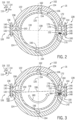
- FIG. 2 is a cross-sectional view of an embodiment of a multi-wall casing 102 having the alignment positioner 100 of the casing alignment 16 as discussed above with reference to FIG. 1 .
- the multi-wall casing 102 includes an outer wall 104 disposed about an inner wall 106.
- the multi-wall casing 102 having the outer and inner walls 104 and 106 may correspond to the multi-wall compressor casing 50 having the inner and outer walls 49 and 51 and/or the multi-wall turbine casing 72 having the inner and outer walls 71 and 73. Accordingly, the following discussion referring to the multi-wall casing 102 is applicable to the multi-wall compressor and turbine casings 50 and 72 of FIG. 1 .
- the outer and inner walls 104 and 106 may be annular walls disposed about a central axis 108, which may correspond to a rotational axis of a turbomachine such as the gas turbine system 10 of FIG. 1 .
- a turbomachine such as the gas turbine system 10 of FIG. 1 .
- the following discussion refers to various positions and orientations of the components. Accordingly, reference may be made to an axial direction or axis 110 along the central axis 108, a circumferential direction or axis 112 disposed circumferentially about the central axis 108, and one or more radial directions or axes relative to the central axis 108.
- the radial directions or axes may correspond to a horizontal direction or axis 114 and a vertical direction or axis 116.
- the components of the multi-wall casing 102 may correspond to a first plane 118 and a second plane 120, which are generally perpendicular to one another.
- the first plane 118 is a horizontal plane extending along the central axis 108 and the horizontal direction or axis 114
- the second plane 120 is a vertical plane extending along the central axis 108 and the vertical direction or axis 116.
- the outer wall 104 includes a plurality of wall sections coupled together at flange couplings, such as wall sections 122 and 124 coupled together at flanged couplings 126 and 128.
- each of the wall sections 122 and 124 may define a semicylindrical section of an annular shaped outer wall 104.
- the flanged coupling 126 includes flanges 130 and 132 extending radially outward from the respective wall sections 122 and 124, while the flanged coupling 128 includes flanges 134 and 136 extending radially outward from the respective wall sections 122 and 124.
- the flanged coupling 126 has a plurality of threaded fasteners coupling together the flanges 130 and 132, such as a male threaded fastener 138 extending through the flanges 130 and 132 and secured by female threaded fasteners 140 and 142 adjacent the respective flanges 130 and 132.
- the female threaded fasteners 140 and 142 may be threaded onto the male threaded fastener 138, thereby compressing the flanges 130 and 132 together at the flanged coupling 126.
- the flanged coupling 128 includes a plurality of male threaded fasteners 144 extending through the flanges 134 and 136, while female threaded fasteners 146 and 148 secure the male threaded fastener 144 about the flanges 134 and 136.
- the female threaded fasteners 146 and 148 may be threaded onto the male threaded fastener 144, thereby compressing the flanges 134 and 136 together at the flanged coupling 128.
- the flanged couplings 126 and 128 may be secured to one another by other removable fasteners and/or fixed couplings, such as welded joints, clamps, brazed joints, dovetail joints, hinged joints, or any combination thereof.
- the inner wall 106 may include a single annular structure, a plurality of inner wall segments coupled together at flanged connections, or another suitable configuration. Additionally, the inner wall 106 includes a plurality of radial protrusions or lips configured to interface with the outer wall 104. In the illustrated embodiment, the inner wall 106 includes radial protrusions or lips 150, 152, 154, and 156, which are disposed in respective recesses 158, 160, 162, and 164 in the outer wall 104. The lips 150 and 152 are disposed in the respective recesses 158 and 160, while the lips 154 and 156 are disposed in the respective recesses 162 and 164. The lips 150 and 152 and recesses 158 and 160 are disposed generally along the first plane 118, which corresponds to the horizontal direction or axis 114.
- the lips 150 and 152 are disposed on diametrically opposite sides of the inner wall 106 relative to the plane 118 extending through the central axis 108 of the rotor (e.g., the lips 150 and 152 are asymmetric relative to the plane 118), while the lips 154 and 156 are disposed on diametrically opposite sides of the inner wall 106 relative to the plane 120 extending through the central axis 108 of the rotor (e.g., the lips 154 and 156 are asymmetric relative to the plane 120).
- the lips 154 and 156 and recesses 162 and 164 are disposed generally along the second plane 120, which corresponds to the vertical direction or axis 116.
- the lip 150 and the recess 158 are disposed above the plane 118, whereas the lip 152 and the recess 160 are disposed below the plane 118 (e.g., rotationally opposite sides of the plane 118).
- the lip 154 and the recess 162 are disposed on one side of the plane 120, whereas the lip 156 and the recess 164 are disposed on the opposite side of the plane 120 (e.g., rotationally opposite sides of the plane 120).
- a bottom surface (or load face) of the lip 150 is disposed along the plane 118 while a top surface (or load face) of the lip 152 is disposed along the plane 118, and a left hand surface (or load face) of the lip 154 is disposed along the plane 120 while a right hand surface (or load face) of the lip 156 is disposed along the plane 120.
- the foregoing arrangement of top, bottom, left hand, and right hand surfaces (or load faces) may be reversed, such as in configurations with an opposite rotational direction of the rotor.
- the multi-wall casing 102 is in a cold or non-operating configuration, such that the multi-wall casing 102 is configured to adjust for changes during operation of the gas turbine system 10.
- the multi-wall casing 102 includes the alignment positioner 100 configured to help align the inner wall 106 relative to outer wall 104 in response to positional changes or movements during operation of the gas turbine system 10.
- the alignment positioner 100 includes a biasing adjuster 170 disposed between the lip 152 and the lower surface of the recess 160 (e.g., below the lip 152) and a shim assembly 172 disposed between the lip 152 and the upper surface of the recess 160 (e.g., above the lip 152).
- the biasing adjuster 170 may include one or more springs 174, such as a leaf spring, a coil spring, a Belleville washer, or any combination thereof.
- the biasing adjuster 170 may include a fluid-driven adjuster (e.g., a gas or liquid driven piston-cylinder assembly), an electric-driven adjuster, or any combination thereof.
- the shim assembly 172 may include a plurality of shims, such as one or more grindable shims 176 and a crowned shim 178 (e.g., shim having a curved or crowned surface, such as a convex surface).
- the shim assembly 172 is configured to adjust a position of the lip 152 relative to the recess 160 (e.g., during construction and assembly).
- the grindable shims 176 may be adjusted in thickness by grinding the surface of the grindable shims 176, thereby helping to provide a better fit between the shim assembly 172 and the recess 160 and to provide a desired position of the inner wall 106 relative to the outer wall 104 (e.g., with lips 150 and 152 on opposite upper and lower sides of the plane 118).
- the biasing adjuster 170 is configured to provide an opposite force to bias the lip 152 (e.g., a biasing force) toward the shim assembly 172.
- the biasing adjuster 170 of the alignment positioner 100 is configured to provide the biasing force to ensure proper alignment between the inner wall 106 and the outer wall 104 during operation of the gas turbine system 10.
- the biasing adjuster 170 may help to bias the inner wall 106 to move (e.g., vertically and/or rotationally) relative to the outer wall 104, thereby helping to align the outer and inner walls 104 and 106.
- FIG. 3 is a cross-sectional view of the multi-wall casing 102 of FIG. 2 , further illustrating changes in the multi-wall casing 102 and the alignment positioner 100 of the casing alignment system 16 during operation of the gas turbine system 10.
- a torque may be applied to the multi-wall casing 102 as indicated by arrow 180 as a result of rotational motion of the rotor within the compressor section 20 or the turbine section 24.
- the outer wall 104 may experience a partial opening or separation at the flanged coupling 126 and 128, as illustrated by openings or separations 182 and 184 at the flanged couplings 126 and 128.
- the lips 150 and 152 may experience some downward vertical movement relative to the outer wall 104.
- the alignment positioner 100 of the casing alignment system 16 helps to bias the inner wall 106 to rotate in the same direction as the applied torque as indicated by arrow 180, thereby helping to overcome or compensate for the downward vertical movement of the inner wall 106. Without the disclosed alignment positioner 100 of the casing alignment system 16, the inner wall 106 may move vertically downward due to the openings 182 and 184, causing a misalignment between central axes of the outer wall 104 and the inner wall 106.
- the alignment positioner 100 of the casing alignment system 16 biases the lip 152 to move upward in a rotational direction along with the direction of torque 180.
- the alignment positioner 100 particularly the biasing adjuster 170 including the spring 174, forces the lip 152 and the inner wall 106 to rotate sufficiently to align the central axis of the outer and inner walls 104 and 106 relative to the central axis 108.
- the alignment positioner 100 may include any one or more types of biasing adjusters 170, including the spring 174, a fluid-driven biasing adjuster, an electric-driven biasing adjuster, a manual biasing adjuster, or any combination thereof.
- FIG. 4 is a partial cross-sectional view of the multi-wall casing 102 of FIG. 2 , further illustrating details of the casing alignment system 16 at the flanged coupling 128 between the outer and inner walls 104 and 106.
- the alignment positioners 100 of the casing alignment system 16 include a plurality of the biasing adjusters 170 (labeled "BA"), which may include one or more types and/or configurations of biasing adjusters 170 as discussed in detail below.
- the biasing adjusters 170 may be disposed partially inside and partially outside of the recess 160 between the flanges 134 and 136 of the flanged coupling 128.
- the recess 160 has a recess portion 190 disposed in the flange 134 and an opposing recess portion 192 disposed in the flange 136.
- the recess 160 may be disposed in a single flange, a symmetric arrangement in the flanges 134 and 136, or any other configuration at the flanged coupling 128.
- the flanges 134 and 136 are coupled together with a plurality of threaded fasteners, such as male threaded fasteners 144 (e.g., threaded bolts) and corresponding female threaded fasteners 148 (e.g., threaded nuts).
- the flanges 134 and 136 may be coupled together with a variety of removable fasteners and/or fixed joints, such as welded joints, brazed joints, clamps, hinges, or any combination thereof.
- the lip 152 extends radially into the recess 160 and is generally disposed below the plane 118.
- the lip 152 includes opposite upper and lower surfaces 194 and 196, which face opposite upper and lower surfaces 198 and 200 of the recess 160.
- the lip 152 includes a wear plate 202 coupled to the lower surface 196 via one or more fasteners 204, such as male threaded fasteners or bolts.
- the recess portion 192 includes a grindable shim 206 coupled to the lower surface 200 via one or more fasteners 208, such as male threaded fasteners or bolts.
- the grindable shim 206 may be ground along one or more of its surfaces during assembly of the turbomachine (e.g., gas turbine system 10) to provide a better fit and proper alignment of the lip 152 in the recess 160.
- the grindable shim 206 also may be aligned relative to the lower surface 200 via one or more alignment keys 210, which extend into corresponding recesses 212, 214, and 216 in the flange 136, the grindable shim 206, and a crowned shim 218.
- the recess portion 192 also may include a biasing adjuster 170 disposed between the grindable shim 206 and the crowned shim 218.
- the shim assembly 172 includes the grindable shim 176 and the crowned shim 178 coupled to the upper surface 198 via one or more threaded fasteners, such as threaded fasteners or bolts 224.
- the fasteners 224 may be recessed into the crowned shim 178 at recesses 226, wherein the fasteners 224 extend through bores in the crowned shim 178 and the grindable shim 176 into the flange 134.
- the shim assembly 172 also may include one or more alignment keys 228, which extend through corresponding recesses 230, 232, and 234 in the flange 134, the grindable shim 176, and the crowned shim 178. Similar to the crowned shim 218, the crowned shim 178 includes a crowned or curved contact surface 236 (e.g., a convex surface) configured to contact the corresponding flat surface 238 of a wear plate 240 coupled to the upper surface 194 of the lip 152.
- the wear plate 240 may be coupled to the lip 152 with a plurality of fasteners 242, such as male threaded fasteners or bolts.
- the grindable shims 176 and 206 may be partially ground to reduce the thicknesses, thereby helping to adjust the position of the lip 152 within the recess 160.
- the grindable shims 176 and 206 may be ground sufficiently to position the upper surface 194 of the lip 152 directly along the plane 118, while the lower surface 196 of the lip 152 is disposed at an offset vertically below the plane 118.
- the alignment positioners 100 of the casing alignment system 16 include a plurality of the biasing adjusters 170.
- the alignment positioners 100 may include a biasing adjuster 170 disposed outside of the flanged coupling 128 at the flange 134.
- the casing alignment system 16 includes an alignment positioner 100 with a biasing adjuster 170 disposed below a head 244 of a shaft 246 coupled with the crowned shim 218.
- the head 244 and the shaft 246 may be parts of a male threaded fastener 248, such as a male threaded bolt.
- the shaft 246 may be coupled to the crowned shim 218 via male threads 250 or another suitable mechanical connection.
- the biasing adjusters 170 disposed inside and outside of the recess 160 may be configured to bias the lip 152 in a rotational or vertically upward direction 252, which corresponds to the direction of the torque 180 as illustrated in FIG. 3 .
- the biasing adjusters 170 of the casing alignment system 16 are configured to move the lip 152 in the direction 252 to help align the inner wall 106 within the outer wall 104. This alignment generally improves or matches the alignment between the central axes of the outer and inner walls 104 and 106.
- FIG. 4 illustrates two biasing adjusters 170
- the casing alignment system 16 may include any number of alignment positioners 100 with biasing adjusters 170 at various locations along the flanged coupling 128.
- FIGS. 5-9 are schematics of embodiments of the biasing adjusters 170 of the alignment positioner 100 of the casing alignment system 16 as illustrated and described above with reference to FIGS. 1-4 .
- FIG. 5 is a schematic of an embodiment of the biasing adjuster 170 including the spring 174.
- the spring 174 includes a coil shaped spring 260.
- the coil shaped spring 260 may include 1, 2, 3, 4, 5, 6, 7, 8, 9, 10, or more loops defining a spiral or helical pattern.
- the alignment positioner 100 may include any number of the springs 174 (e.g., coil shaped springs 260) arranged in series and/or parallel with one another.
- FIG. 6 is a schematic of an embodiment of the biasing adjuster 170 of the alignment positioner 100, further illustrating an embodiment of the spring 174.
- the spring 174 includes a leaf spring 270 having a curved plate 272 extending between opposite ends 274 and 276.
- the curved plate 272 may have a radius selected to provide a desired spring force for the biasing adjuster 170.
- the alignment positioner 100 may include any number of the springs 174 (e.g., leaf springs 270) arranged in series and/or parallel with one another.
- the spring 174 may include a plurality of the leaf springs 270 stacked one over another in a series arrangement, e.g., as a plurality of leaf spring layers.
- FIG. 7 is a schematic of an embodiment of the biasing adjuster 170 of the alignment positioner 100, illustrating an embodiment of the spring 174.
- the spring 174 includes a Belleville washer assembly 280 having a plurality of Belleville washers 282.
- the Belleville washers 282 each include a conical shaped wall 284 extending from an outer annular edge 286 to an inner annular bore 288.
- the Belleville washer assembly 280 may arrange the plurality of Belleville washers 282 in a variety of configurations, such as a first set 292 of the Belleville washers 282 facing a second set 294 of the Belleville washers 282.
- the first set 292 has the conical shaped wall 284 extending outwardly away from the inner bore 288 in a direction away from the second set 294, while the second set 294 has the conical shaped wall 284 extending outwardly away from the inner bore 288 in a direction away from the first set 292.
- the Belleville washer assembly 280 may include any number and arrangement of Belleville washers 282.
- the springs 174 e.g., coil shaped springs 260, leaf springs 270, and Belleville washers 282
- the springs 174 may be used in combination with one another, e.g., in series and/or parallel arrangements.
- FIG. 8 is a schematic of an embodiment of a biasing adjuster 170 of the alignment positioner 100 of FIGS. 1-4 , further illustrating an electric-driven alignment positioner or biasing adjuster 300.
- the biasing adjuster 300 includes an electric drive 302 coupled to a gear box 304, which in turn is coupled to a biasing plate 306.
- the electric drive 302 may include an AC motor, a DC motor, or a combination thereof.
- the electric drive 302 may be coupled to the gear box 304 with a shaft 308, while the gear box 304 may be coupled to the biasing plate 306 with a shaft 310.
- the gear box 304 may include a plurality of gears configured to change a gear ratio to provide a mechanical advantage to drive the biasing plate 306.
- the electric drive 302 also may be coupled to the controller 76 of the control system 14, which may be configured to actuate the electric drive 302 in response to feedback from the sensors 86. Accordingly, during operation of the gas turbine system 10, the controller 76 may trigger operation of the electric drive 302 to move the biasing plate 306 to provide adjustments of the lip 152 as discussed in detail above.
- FIG. 9 is a schematic of an embodiment of the biasing adjuster 170 of the alignment positioner 100 as discussed with detail above with reference to FIGS. 1-4 .
- the biasing adjuster 170 may include a fluid-driven alignment positioner or biasing adjuster 320, which includes a piston cylinder assembly 322 coupled to a fluid supply 324.
- the piston cylinder assembly 322 includes a piston 326 disposed in a cylinder 328 of a housing 330, wherein the piston 326 separates the cylinder 328 between chambers 332 and 334.
- the fluid supply 324 may include a fluid tank, a fluid pump or compressor, one or more fluid valves, or any combination thereof, configured to control a flow of fluid into the chamber 332 or the chamber 334.
- the fluid supply 324 may be controlled by the controller 76 in response to feedback from the sensors 86, thereby providing fluid pressure into the chamber 332 to move the piston 326 upwardly or into the chamber 334 to move the piston 326 downwardly to control the position of a biasing plate 336.
- the biasing plate 336 is coupled to the piston 326 via a shaft 338, and the biasing plate 336 may be coupled to the lip 152 as discussed above.
- the fluid supply 324 is controlled by the controller 76 to force movement of the piston 326, thereby driving the biasing plate 336 to move the lip 152 and the inner wall 106 to improve alignment between the outer and inner walls 104 and 106.
- FIG. 10 is a partial cross-sectional view of the multi-wall casing 102 of FIG. 2 , further illustrating details of the casing alignment system 16 at a location along the flanged coupling 128.
- the components of FIG. 10 are the same as described in detail above with reference to FIGS. 1-4 , unless noted otherwise.
- the components of the flanged coupling 128, the shim assembly 172, and the lip 152 are substantially the same as discussed in detail above.
- the shim assembly 172 has the crowned shim 178 and the grindable shim 176 disposed in the recess portion 190, such that the crowned surface 236 contacts the flat surface 238 of the wear plate 240.
- the casing alignment system 16 of FIG. 10 differs from FIG. 4 in the recess portion 192, particularly with different features at the grindable shim 206 and in the replacement of the crowned shim 218 and the biasing adjuster 170 with the leaf spring 270 of FIG. 6 .
- the biasing adjuster 170 of the alignment positioner 100 includes the spring 174 in the recess portion 192 between the wear plate 202 and the grindable shim 206.
- the grindable shim 206 includes opposite lips or protruding portions 350 disposed about a central recess 352.
- the spring 174 includes the leaf spring 270 having the curved plate 272 extending from a first end 274 to a second, opposite end 276, as illustrated in FIG. 6 .
- the opposite ends 274 and 276 are disposed in the central recess 352 between the lips or protruding portions 350, while the curved plate 272 extends upwardly or outwardly away from the grindable shim 206 toward the wear plate 202.
- the curved plate 272 contacts the flat surface 222 of the wear plate 202, thereby applying a biasing force against the wear plate 202 to bias the lip 152 in the upward or circumferential direction 252 as discussed above with reference to FIG. 4 .
- FIG. 10 illustrates the leaf spring 270 as the biasing adjuster 170
- the casing alignment system 16 may include any one or all of the biasing adjusters 170 as discussed above with reference to FIGS. 1-9 .
- the leaf spring 270 is configured to automatically provide a pre-load or biasing force against the lip 152, thereby helping to rotate or move the inner wall 106 relative to the outer wall 104 as the torque 180 is applied during operation of the gas turbine system 10.
- the leaf spring 270 helps to align the inner wall 106 with the outer wall 104 via movement at the lip 152.
- FIG. 11 is a partial cross-sectional view of the multi-wall casing 102 of FIG. 2 , further illustrating an embodiment of the flanged coupling 128 having another biasing adjuster 170 at a location along the flanged coupling 128.
- the components of FIG. 11 are the same as described in detail above with reference to FIGS. 1-4 , unless noted otherwise.
- the components of the flanged coupling 128, the shim assembly 172, the lip 152, and other like elements are generally the same as discussed in detail above with reference to FIGS. 4 and 10 .
- the casing alignment system 16 of FIG. 11 differs from FIG.
- the biasing adjuster 170 disposed between the wear plate 202 and the grindable shim 206 in the recess portion 192 includes the piston cylinder assembly 360 biased by a spring 174, including the Belleville washer assembly 280 as discussed above with reference to FIG. 7 .
- the piston cylinder assembly 360 includes a piston or contact plate 362 coupled to a shaft 364, which is configured to move along an axis 366 in a cylinder or bore 368 in the bottom surface 200 of the recess portion 192.
- the piston or contact plate 362 can move upwardly and downwardly relative to and through the grindable shim 206, and the Belleville washer assembly 280 provides an upward biasing force of the piston or contact plate 362 against a crowned or curved surface 370 of the wear plate 202.
- the spring 174 is shown as the Belleville washer assembly 280, the spring 174 may include the coil-shaped spring 260 of FIG. 5 , the leaf spring 270 of FIG. 6 , or any other suitable spring type or configuration alone or in combination with the Belleville washer assembly 280.
- the shaft 364 of the piston cylinder assembly 360 may be coupled to the electric-drive alignment positioner or biasing adjuster 300 of FIG. 8 and/or the fluid-drive alignment positioner or biasing adjuster 320 of FIG. 9 .
- the biasing adjuster 174 having the piston cylinder assembly 360 and the spring 174 of FIG. 11 helps to bias the lip 152 and the inner wall 106 in the upward or circumferential direction 252 to compensate for any downward movement of the inner wall 106 relative to the outer wall 104.
- the biasing adjuster 170 is configured to help align central axes of the outer and inner walls 104 and 106 during operation of the gas turbine system 10.
- alignment positioners of a casing alignment system configured to align inner and outer walls of a multi-wall casing of a turbomachine, such as a compressor, a turbine, or a combination thereof.
- the alignment positioners may include one or more biasing adjusters, such as springs, fluid-driven alignment positioners or biasing adjusters, electric-driven alignment positioners or biasing adjusters, or any combination thereof.
- the alignment positioners apply a biasing force to the inner wall, such as at a lip in a recess of a flanged coupling of the outer wall, thereby biasing the inner wall to move into alignment with the outer wall.
- the flanged coupling may open, the inner wall may drop downwardly relative to the outer wall, and the alignment positioners may bias the inner wall to rotate and move upwardly to align the central axes of the inner and outer walls.
- the clearance between the rotor (e.g., rotary blades coupled to the rotor) and the inner wall may be non-uniform circumferentially about the rotational axis, which can reduce the efficiency and performance of the turbomachine, increase risk of a rub condition, and cause other problems during operation of the turbomachine.
- a system in certain embodiments, includes a casing alignment system configured to align an inner wall with an outer wall of a multi-wall casing of a turbomachine having a rotor.
- the casing alignment system includes a first alignment positioner configured to bias a first lip of the inner wall in a direction of rotation of the rotor disposed within the multi-wall casing.
- the first alignment positioner includes a spring.
- the first alignment positioner includes a fluid-driven alignment positioner.
- the first alignment positioner includes an electric-driven alignment positioner.
- any preceding clause including a second alignment positioner configured to bias the first lip of the inner wall in the direction of rotation of the rotor disposed within the multi-wall casing, wherein the first and second alignment positioners are different from one another.
- any preceding clause including the inner wall of the multi-wall casing, wherein the inner wall includes a second lip, the first and second lips are disposed on diametrically opposite sides of the inner wall relative to a first plane extending through a rotational axis of the rotor, the first and second lips extend radially outward from the inner wall, and load faces of the first and second lips are disposed on opposite sides of the first plane.
- first lip has an upper surface disposed along the first plane
- second lip has a lower surface disposed along the first plane
- the multi-wall casing having the outer wall disposed about the inner wall, wherein the outer wall includes first and second wall sections coupled together at a first flanged coupling, and the first lip of the inner wall extends radially into a first recess in the outer wall adjacent the first flanged coupling.
- the first alignment positioner includes a biasing adjuster disposed in the first recess.
- the first alignment positioner includes a biasing adjuster disposed outside of the first recess.
- the first alignment positioner includes a shaft extending from the biasing adjuster to a crowned shim in contact with the first lip inside the first recess.
- turbomachine includes a compressor, a turbine, or both.
- a method includes aligning an inner wall with an outer wall of a multi-wall casing of a turbomachine via a casing alignment system, wherein the aligning includes biasing, via a first alignment positioner of the casing alignment system, a first lip of the inner wall in a direction of rotation of a rotor of the turbomachine disposed within the multi-wall casing.
- biasing the first lip includes applying a force on the first lip within a first recess at a first flanged coupling between first and second sections of the outer wall.
- biasing the first lip includes rotating the inner wall in the direction of rotation in response to a downward vertical movement of the inner wall relative to the outer wall of the multi-wall casing.
- a system may include a turbomachine having a rotor disposed within a multi-wall casing with an outer wall disposed about an inner wall.
- the outer wall has first and second wall sections coupled together at a first flanged coupling.
- the inner wall has first and second lips extending radially outward from the inner wall on diametrically opposite sides of the inner wall relative to a first plane extending through a rotational axis of the rotor, wherein load faces of the first and second lips are disposed on opposite sides of the first plane..
- the first lip extends radially into a first recess in the outer wall adjacent the first flanged coupling.
- the casing alignment system includes a first alignment positioner configured to bias the first lip of the inner wall in a direction of rotation of the rotor disposed within the multi-wall casing.
Landscapes
- Engineering & Computer Science (AREA)
- Mechanical Engineering (AREA)
- General Engineering & Computer Science (AREA)
- Structures Of Non-Positive Displacement Pumps (AREA)
Abstract
Description
- The present application relates generally to a system and method for aligning inner and outer walls of a casing of a turbomachine during operation of the turbomachine.
- A turbomachine, such as a compressor or turbine, may include a multi-wall casing disposed about a central rotor having a plurality of rotary blades. The multi-wall casing may include inner and outer walls, such as an outer annular wall disposed about an inner annular wall. Unfortunately, during operation, the inner and outer walls of the multi-wall casing may move relative to one another, resulting in eccentricity or misalignment of axes between the inner and outer walls. For example, in response to torque applied due to rotation of the central rotor, flanges between segments of the outer wall may partially open, resulting in movement (e.g., downward movement) of the inner casing relative to the outer casing. The eccentricity may create problems with a clearance between the central rotor, particularly the rotary blades, and the inner wall. For example, as the eccentricity increases, the turbomachine may experience greater variability in the clearance circumferentially about a rotational axis of the turbomachine. The greater variability in the clearance may reduce the efficiency of the turbomachine and increase risk of a rub condition between the rotary blades and the inner wall.
- Certain embodiments commensurate in scope with the originally claimed subject matter are summarized below. These embodiments are not intended to limit the scope of the claimed embodiments, but rather these embodiments are intended only to provide a brief summary of possible forms of the subject matter. Indeed, the presently claimed embodiments may encompass a variety of forms that may be similar to or different from the embodiments set forth below.
- In certain embodiments, a system includes a casing alignment system configured to align an inner wall with an outer wall of a multi-wall casing of a turbomachine having a rotor. The casing alignment system includes a first alignment positioner configured to bias a first lip of the inner wall in a direction of rotation of the rotor disposed within the multi-wall casing.
- In certain embodiments, a method includes aligning an inner wall with an outer wall of a multi-wall casing of a turbomachine via a casing alignment system, wherein the aligning includes biasing, via a first alignment positioner of the casing alignment system, a first lip of the inner wall in a direction of rotation of a rotor of the turbomachine disposed within the multi-wall casing.
- In certain embodiments, a system may include a turbomachine having a rotor disposed within a multi-wall casing with an outer wall disposed about an inner wall. The outer wall has first and second wall sections coupled together at a first flanged coupling. The inner wall has first and second lips extending radially outward from the inner wall on diametrically opposite sides of the inner wall relative to a first plane extending through a rotational axis of the rotor, wherein load faces of the first and second lips are disposed on opposite sides of the first plane. The first lip extends radially into a first recess in the outer wall adjacent the first flanged coupling. The casing alignment system includes a first alignment positioner configured to bias the first lip of the inner wall in a direction of rotation of the rotor disposed within the multi-wall casing.
- These and other features, aspects, and advantages of the presently disclosed techniques will become better understood when the following detailed description is read with reference to the accompanying drawings in which like characters represent like parts throughout the drawings, wherein:
-
FIG. 1 is a schematic of an embodiment of a gas turbine system having a casing alignment system configured to align inner and outer walls of a multi-wall casing of a compressor section and/or a turbine section; -
FIG. 2 is a cross-sectional axial view of a multi-wall casing having the casing alignment system ofFIG. 1 in a cold condition, illustrating an alignment positioner having a biasing adjuster with a spring disposed in a recess at a flanged coupling; -
FIG. 3 is cross-sectional axial view of the multi-wall casing having the casing alignment system ofFIG. 2 in an operating condition, illustrating the alignment positioner biasing movement (e.g., upward and/or rotational movement) of the inner wall to improve alignment between the inner and outer walls of the multi-wall casing; -
FIG. 4 is a partial cross-sectional axial view of the multi-wall casing ofFIG. 2 , further illustrating details of the alignment positioner at the flanged coupling, including internal and external biasing adjusters of the alignment positioner; -
FIG. 5 is a schematic view of an embodiment of the biasing adjuster of the alignment positioner of the casing alignment system ofFIGS. 1-4 , illustrating the biasing adjuster including a spring (e.g., a coil-shaped spring); -
FIG. 6 is a schematic view of an embodiment of the biasing adjuster of the alignment positioner of the casing alignment system ofFIGS. 1-4 , illustrating the biasing adjuster including a spring (e.g., a leaf spring); -
FIG. 7 is a schematic view of an embodiment of the biasing adjuster of the alignment positioner of the casing alignment system ofFIGS. 1-4 , illustrating the biasing adjuster including a spring (e.g., a Belleville washer assembly); -
FIG. 8 is a schematic view of an embodiment of the biasing adjuster of the alignment positioner of the casing alignment system ofFIGS. 1-4 , illustrating the biasing adjuster including an electric-driven alignment positioner or biasing adjuster; -
FIG. 9 is a schematic view of an embodiment of the biasing adjuster of the alignment positioner of the casing alignment system ofFIGS. 1-4 , illustrating the biasing adjuster including a fluid-driven alignment positioner or biasing adjuster; -
FIG. 10 is a partial cross-sectional axial view of the multi-wall casing ofFIGS. 2 and4 , further illustrating details of the alignment positioner at the flanged coupling, including the biasing adjuster (e.g., leaf spring) ofFIG. 6 ; and -
FIG. 11 is a partial cross-sectional axial view of the multi-wall casing ofFIGS. 2 and4 , further illustrating details of the alignment positioner at the flanged coupling, including the biasing adjuster (e.g., Belleville washer assembly) ofFIG. 7 . - One or more specific embodiments of the presently disclosed systems are described below. In an effort to provide a concise description of these embodiments, all features of an actual implementation may not be described in the specification. It should be appreciated that in the development of any such actual implementation, as in any engineering or design project, numerous implementation-specific decisions must be made to achieve the developers' specific goals, such as compliance with system-related and business-related constraints, which may vary from one implementation to another. Moreover, it should be appreciated that such a development effort might be complex and time consuming, but would nevertheless be a routine undertaking of design, fabrication, and manufacture for those of ordinary skill having the benefit of this disclosure.
- When introducing elements of various embodiments of the presently disclosed embodiments, the articles "a," "an," "the," and "said" are intended to mean that there are one or more of the elements. The terms "comprising," "including," and "having" are intended to be inclusive and mean that there may be additional elements other than the listed elements.
- As discussed in detail below, the disclosed embodiments provide various alignment positioners of a casing alignment system configured to align inner and outer walls of a multi-wall casing of a turbomachine, such as a compressor, a turbine, or a combination thereof. The alignment positioners, which may include biasing adjusters such as springs, fluid-driven adjusters, and electric-driven adjusters, are configured to bias the inner wall to compensate for undesirable movement of the inner wall relative to the outer wall during operation of the turbomachine. For example, the alignment adjusters may compensate for a downward vertical movement of the inner wall by causing an upward movement on one side of the inner wall, thereby causing rotation of the inner wall to help realign the central axis of the inner wall with the central axis of the outer wall. Details of the casing alignment system are discussed in detail below with reference to the drawings.
-
FIG. 1 is a block diagram of an embodiment of agas turbine system 10 having agas turbine engine 12 coupled to acontrol system 14. As discussed in further detail below, thegas turbine system 10 may include acasing alignment system 16. The various features of thecasing alignment system 16 are discussed below with reference toFIGS. 1-11 , and the various features may be used in any suitable combination with one another. However, before moving on to thecasing alignment system 16, thegas turbine system 10 will be described as one possible turbomachine context for use of thecasing alignment system 16. - The
gas turbine engine 12 includes anair intake section 18, acompressor section 20, acombustor section 22, aturbine section 24, aload 26, and anexhaust section 28. Theair intake section 18 may include a duct having one or more silencer baffles, fluid injection systems (e.g., heated fluid injection for anti-icing), air filters, or any combination thereof. Thecompressor section 20 may include anupstream inlet duct 30 having abell mouth 32, wherein theinlet duct 30 includes aninner hub 34, anouter wall 36 disposed circumferentially about theinner hub 34 to define an air intake flow path, a plurality ofstationary vanes 38 extending radially between theinner hub 34 and theouter wall 36 within the air intake flow path, and a plurality of inlet guide vanes (IGVs) 40 arranged circumferentially about a central axis within the air intake flow path. Theinlet guide vanes 40 also may be coupled to one ormore actuators 42, which are communicatively coupled to and controlled by thecontrol system 14. In operation, thecontrol system 14 is configured to adjust the position (e.g., angular position) of theinlet guide vanes 40 to vary the flow of intake air into thecompressor section 20 during operation of thegas turbine engine 12. - The
compressor section 20 includes one ormore compressor stages 44, wherein eachcompressor stage 44 includes a plurality ofcompressor blades 46 coupled to a compressor shaft 48 within a compressor casing 50 (e.g., a multi-wall compressor casing having anouter wall 51 disposed about an inner wall 49), and a plurality ofcompressor vanes 52 coupled to the compressor casing 50 (e.g., inner wall 49). Thecompressor blades 46 and thecompressor vanes 52 are arranged circumferentially about a central axis of the compressor shaft 48 within eachcompressor stage 44. Thecompressor stages 44 may include between 1 and 20 or more compressor stages. Additionally, thecompressor stages 44 alternate between sets of thecompressor blades 46 and sets of thecompressor vanes 52 in the direction of flow through thecompressor section 20. In operation, the compressor stages 44 progressively compress the intake air (represented by arrows 88) before delivery to thecombustor section 22. - The
combustor section 22 includes one ormore combustors 54 each having one ormore fuel nozzles 56. In certain embodiments, thecombustor section 22 may have a singleannular combustor 54 extending around a central axis of thegas turbine engine 12. However, in some embodiments, thecombustor section 22 may include 2, 3, 4, 5, 6, ormore combustors 54 spaced circumferentially about the central axis of thegas turbine engine 12. Thefuel nozzles 56 receive compressedair 58 from thecompressor section 20 andfuel 60 from afuel supply system 62, mix the fuel and air, and ignite the mixture to createhot combustion gases 64, which then exit eachcombustor 54 and enter theturbine section 24. - The
turbine section 24 includes one ormore turbine stages 66, wherein eachturbine stage 66 includes a plurality ofturbine blades 68 arranged circumferentially about and coupled to aturbine shaft 70 inside of a turbine casing 72 (e.g., a multi-wall turbine casing having anouter wall 73 disposed about an inner wall 71), and a plurality ofturbine vanes 74 arranged circumferentially about theturbine shaft 70. Theturbine stages 66 may include between 1 and 10 or more turbine stages. Additionally, the turbine stages 66 alternate between sets of theturbine blades 68 and sets of theturbine vanes 74 in the direction of flow through theturbine section 24. In operation, thehot combustion gases 64 progressively expand and drive rotation of theturbine blades 68 in the turbine stages 66. - The
load 26 may include an electrical generator, a machine, or some other driven load. Theload 26 may be disposed at the hot end of thegas turbine engine 12 as illustrated inFIG. 1 , or theload 26 may be disposed at the cold end of the gas turbine engine 12 (e.g., adjacent the compressor section 20). Theexhaust section 28 may include an exhaust duct, exhaust treatment equipment, silencers, or any combination thereof. In some embodiments, theexhaust section 28 may include a heat exchanger, such as a heat recovery steam generator (HRSG) configured to generate steam to drive a steam turbine. - The
control system 14 may include one ormore controllers 76, each having aprocessor 78,memory 80,instructions 82 stored on thememory 80 and executable by theprocessor 78, andcommunications circuitry 84 configured to communicate with various sensors 86 (designated as "S") and actuators distributed throughout thegas turbine system 10. Thesensors 86 may be coupled to and monitor conditions at theair intake section 18, thecompressor section 20, thecombustors 54 of thecombustor section 22, theturbine section 24, theload 26, and theexhaust section 28. Thecontrol system 14 is configured to receive feedback from thesensors 86 to facilitate adjustments of various operating parameters of thegas turbine engine 12, such as the air intake flow, the fuel supply from thefuel supply system 62 to thecombustors 54, operation of exhaust treatment equipment in theexhaust section 28, or any combination thereof. For example, thecontrol system 14 may be configured to control theactuators 42 to change an angular position of theinlet guide vanes 40, thereby controlling the intake flow from theair intake section 18 into thecompressor section 20. - In operation, the
gas turbine system 10 receives air into theinlet duct 30 from theair intake section 18 as indicated byarrows 88, theinlet guide vanes 40 are controlled by theactuators 42 to adjust an angular position of theinlet guide vanes 40 for adjusting air flow into thecompressor section 20, and thecompressor section 20 is configured to compress the air flow being supplied into thecombustor section 22. For example, eachstage 44 of thecompressor section 20 compresses the air flow with a plurality of theblades 46. Thecompressed air flow 58 then enters each of thecombustors 54, where thefuel nozzles 56 mix thecompressed air flow 58 withfuel 60 from thefuel supply system 62. The mixture of fuel and air is then combusted in each combustor 54 to generate thehot combustion gases 64, which flow into theturbine section 24 to drive rotation of theturbine blades 68 in each of thestages 66. The rotation of theturbine blades 68 drives rotation of theturbine shaft 70, which in turn drives rotation of theload 26 and thecompressor section 20 via ashaft 90 coupled to theload 26 and ashaft 92 coupled to the compressor shaft 48. Theturbine section 24 then discharges anexhaust gas 94 into theexhaust section 28 for final treatment and/or discharge into the environment. - As discussed in detail below, the
multi-wall compressor casing 50 and/or themulti-wall turbine casing 72 may experiences changes (e.g., increases) in eccentricity during operation of thegas turbine system 10. The changes in eccentricity may be caused by torque, thermal expansion or contraction, or any combination thereof, during operation of thegas turbine system 10, resulting in relative movement between the inner walls (e.g., 49 or 71) and the outer walls (e.g., 51 or 73). For example, the outer walls (e.g., 51 or 73) may partially open at flanged connections between adjacent wall sections, thereby causing the inner walls (e.g., 49 or 71) to move relative to the outer walls (e.g., 51 or 73). The relative movement may include vertical movement (e.g., downward vertical movement) of the inner walls (e.g., 49 or 71) relative to the outer walls (e.g., 51 or 73), thereby causing misalignment between the central axes of the inner and outer walls (e.g., between 49 and 51 and between 71 and 73). - The
casing alignment system 16 includes one or more alignment positioners 100 (seeFIGS. 2-11 ) configured to help align the central axes of the inner and outer walls (e.g., between 49 and 51 and between 71 and 73) in a manner opposing the foregoing relative movement of the inner walls (e.g., 49 or 71) relative to the outer walls (e.g., 51 or 73). In certain embodiments, thealignment positioners 100 include mechanical springs (e.g., leaf springs, coil springs, Belleville washers, etc.), fluid-driven positioners (e.g., liquid or gas driven piston-cylinder positioners), electric-driven positioners (e.g., electric motor driven positioners), manual positioners (e.g., handwheel operated screw assembly), or any combination thereof. The mechanical springs automatically provide a biasing force to oppose the foregoing relative movement of the inner walls (e.g., 49 or 71) relative to the outer walls (e.g., 51 or 73). The manual positioners may be operated by a technician in response to sensor feedback from thesensors 86 and/or other observations by the technician. The fluid-driven positioners and the electric-driven positioners may be operated by thecontrol system 14 in response to sensor feedback from thesensors 86. - In the illustrated embodiment, the
control system 14 and thesensors 86 may be part of thecasing alignment system 16. For example, thesensors 86 may monitor eccentricity, clearance between rotating and stationary components, vibration, strain, torque, position (e.g., angular position, vertical position, or horizontal position), or other parameters indicative of relative movement between inner and outer walls of a multi-wall casing of thecompressor section 20 and/or the turbine section 24 (e.g., inner andouter walls multi-wall compressor casing 50 and inner andouter walls sensors 86 may be disposed at a plurality of axial positions along a rotational axis of thegas turbine system 10, and a plurality of circumferential positions about the rotational axis. For example, at one ormore stages sensors 86 may be disposed at one or more locations corresponding to positions of the blades (e.g., 46 and 68) and/or vanes (e.g., 52 and 74). Thesensors 86 may monitor relative movement between the inner and outer walls (e.g., 49, 51, 71, and 73) by monitoring a change in distance between the inner and outer walls at various circumferential positions about the axis, a change in distance between the inner and outer walls relative to a reference structure, or a combination thereof. Additionally, thesensors 86 may monitor relative movement between the inner and outer walls (e.g., 49, 51, 71, and 73) by monitoring a change in clearance between the respective inner wall and the rotating blades (e.g., 46 and 68) at various circumferential positions about the axis. Additionally, thesensors 86 may monitor a torque and/or a rotational speed of thecompressor section 20 and/or theturbine section 24 as an indication of a torque-induced movement and/or a speed-induced movement between the inner and outer walls (e.g., 49, 51, 71, and 73). - The
control system 14 is configured to analyze sensor data from thesensors 86, to determine relative movement between the inner and outer walls (e.g., 49, 51, 71, and 73), to output data indicative of the relative movement to an electronic display, and/or to trigger an alarm (e.g., an audio and/or visual alarm) if the relative movement exceeds one or more thresholds. Thecontrol system 14 also may be configured to control one or more of thealignment positioners 100 of thecasing alignment system 16 to adjust an alignment between the inner and outer walls (e.g., 49, 51, 71, and 73), such as by causing an opposite relative movement between the inner and outer walls (e.g., 49, 51, 71, and 73) to increase alignment between the inner and outer walls (e.g., 49, 51, 71, and 73). The opposite relative movement may correspond to a horizontal movement, a vertical movement, and/or a rotational movement of the inner wall (e.g., 49 or 71) relative to the outer wall (e.g., 51 or 73), wherein the opposite relative movement is generally opposite to the relative movement caused by operation of the gas turbine system 10 (e.g., torque-induced movement or speed-induced movement). - In some embodiments, the
casing alignment system 16 automatically responds to changes in the relative position of the inner and outer walls (e.g., 49, 51, 71, and 74) without a control action by thecontrol system 14, such as by using mechanical springs as thealignment positioners 100. However, thecasing alignment system 16 may include alignment positioners 100 (e.g., fluid-driven positioners and electric-driven positioners) directly controlled by thecontrol system 14 to improve alignment between the central axes of the inner and outer walls (e.g., 49, 51, 71, and 73). Various features of thecasing alignment system 16 are discussed in further detail below. -
FIG. 2 is a cross-sectional view of an embodiment of amulti-wall casing 102 having thealignment positioner 100 of thecasing alignment 16 as discussed above with reference toFIG. 1 . In the illustrated embodiment, themulti-wall casing 102 includes anouter wall 104 disposed about aninner wall 106. Themulti-wall casing 102 having the outer andinner walls multi-wall compressor casing 50 having the inner andouter walls multi-wall turbine casing 72 having the inner andouter walls multi-wall casing 102 is applicable to the multi-wall compressor andturbine casings FIG. 1 . - As illustrated in
FIG. 2 , the outer andinner walls central axis 108, which may correspond to a rotational axis of a turbomachine such as thegas turbine system 10 ofFIG. 1 . Additionally, the following discussion refers to various positions and orientations of the components. Accordingly, reference may be made to an axial direction oraxis 110 along thecentral axis 108, a circumferential direction oraxis 112 disposed circumferentially about thecentral axis 108, and one or more radial directions or axes relative to thecentral axis 108. For example, the radial directions or axes may correspond to a horizontal direction oraxis 114 and a vertical direction oraxis 116. Furthermore, the components of themulti-wall casing 102 may correspond to afirst plane 118 and asecond plane 120, which are generally perpendicular to one another. In certain embodiments, thefirst plane 118 is a horizontal plane extending along thecentral axis 108 and the horizontal direction oraxis 114, and thesecond plane 120 is a vertical plane extending along thecentral axis 108 and the vertical direction oraxis 116. - The
outer wall 104 includes a plurality of wall sections coupled together at flange couplings, such aswall sections flanged couplings wall sections outer wall 104. Theflanged coupling 126 includesflanges respective wall sections flanged coupling 128 includesflanges respective wall sections flanged coupling 126 has a plurality of threaded fasteners coupling together theflanges fastener 138 extending through theflanges fasteners respective flanges fasteners fastener 138, thereby compressing theflanges flanged coupling 126. Similarly, theflanged coupling 128 includes a plurality of male threadedfasteners 144 extending through theflanges fasteners fastener 144 about theflanges fasteners fastener 144, thereby compressing theflanges flanged coupling 128. In certain embodiments, theflanged couplings - The
inner wall 106 may include a single annular structure, a plurality of inner wall segments coupled together at flanged connections, or another suitable configuration. Additionally, theinner wall 106 includes a plurality of radial protrusions or lips configured to interface with theouter wall 104. In the illustrated embodiment, theinner wall 106 includes radial protrusions orlips respective recesses outer wall 104. Thelips respective recesses lips respective recesses lips first plane 118, which corresponds to the horizontal direction oraxis 114. - In the illustrated embodiment, the
lips inner wall 106 relative to theplane 118 extending through thecentral axis 108 of the rotor (e.g., thelips lips inner wall 106 relative to theplane 120 extending through thecentral axis 108 of the rotor (e.g., thelips lips second plane 120, which corresponds to the vertical direction oraxis 116. However, in the illustrated embodiment, thelip 150 and therecess 158 are disposed above theplane 118, whereas thelip 152 and therecess 160 are disposed below the plane 118 (e.g., rotationally opposite sides of the plane 118). Similarly, thelip 154 and therecess 162 are disposed on one side of theplane 120, whereas thelip 156 and therecess 164 are disposed on the opposite side of the plane 120 (e.g., rotationally opposite sides of the plane 120). - In the illustrated embodiment, a bottom surface (or load face) of the
lip 150 is disposed along theplane 118 while a top surface (or load face) of thelip 152 is disposed along theplane 118, and a left hand surface (or load face) of thelip 154 is disposed along theplane 120 while a right hand surface (or load face) of thelip 156 is disposed along theplane 120. In some embodiments, the foregoing arrangement of top, bottom, left hand, and right hand surfaces (or load faces) may be reversed, such as in configurations with an opposite rotational direction of the rotor. In the illustrated configuration, themulti-wall casing 102 is in a cold or non-operating configuration, such that themulti-wall casing 102 is configured to adjust for changes during operation of thegas turbine system 10. - At the
flanged coupling 128, themulti-wall casing 102 includes thealignment positioner 100 configured to help align theinner wall 106 relative toouter wall 104 in response to positional changes or movements during operation of thegas turbine system 10. For example, thealignment positioner 100 includes abiasing adjuster 170 disposed between thelip 152 and the lower surface of the recess 160 (e.g., below the lip 152) and ashim assembly 172 disposed between thelip 152 and the upper surface of the recess 160 (e.g., above the lip 152). The biasingadjuster 170 may include one ormore springs 174, such as a leaf spring, a coil spring, a Belleville washer, or any combination thereof. Additionally, the biasingadjuster 170 may include a fluid-driven adjuster (e.g., a gas or liquid driven piston-cylinder assembly), an electric-driven adjuster, or any combination thereof. - The
shim assembly 172 may include a plurality of shims, such as one or moregrindable shims 176 and a crowned shim 178 (e.g., shim having a curved or crowned surface, such as a convex surface). Theshim assembly 172 is configured to adjust a position of thelip 152 relative to the recess 160 (e.g., during construction and assembly). For example, thegrindable shims 176 may be adjusted in thickness by grinding the surface of thegrindable shims 176, thereby helping to provide a better fit between theshim assembly 172 and therecess 160 and to provide a desired position of theinner wall 106 relative to the outer wall 104 (e.g., withlips - The biasing
adjuster 170 is configured to provide an opposite force to bias the lip 152 (e.g., a biasing force) toward theshim assembly 172. As discussed in further detail below, the biasingadjuster 170 of thealignment positioner 100 is configured to provide the biasing force to ensure proper alignment between theinner wall 106 and theouter wall 104 during operation of thegas turbine system 10. For example, the biasingadjuster 170 may help to bias theinner wall 106 to move (e.g., vertically and/or rotationally) relative to theouter wall 104, thereby helping to align the outer andinner walls -
FIG. 3 is a cross-sectional view of themulti-wall casing 102 ofFIG. 2 , further illustrating changes in themulti-wall casing 102 and thealignment positioner 100 of thecasing alignment system 16 during operation of thegas turbine system 10. In particular, during operation of thegas turbine system 10, a torque may be applied to themulti-wall casing 102 as indicated byarrow 180 as a result of rotational motion of the rotor within thecompressor section 20 or theturbine section 24. As torque is applied to thegas turbine system 10, theouter wall 104 may experience a partial opening or separation at theflanged coupling separations flanged couplings separations lips outer wall 104. - As the
inner wall 106 moves downwardly in therecesses openings alignment positioner 100 of thecasing alignment system 16 helps to bias theinner wall 106 to rotate in the same direction as the applied torque as indicated byarrow 180, thereby helping to overcome or compensate for the downward vertical movement of theinner wall 106. Without the disclosedalignment positioner 100 of thecasing alignment system 16, theinner wall 106 may move vertically downward due to theopenings outer wall 104 and theinner wall 106. Rather than allowing this misalignment or eccentricity, thealignment positioner 100 of thecasing alignment system 16 biases thelip 152 to move upward in a rotational direction along with the direction oftorque 180. As a result, thealignment positioner 100, particularly the biasingadjuster 170 including thespring 174, forces thelip 152 and theinner wall 106 to rotate sufficiently to align the central axis of the outer andinner walls central axis 108. Although thealignment positioner 100 ofFIGS. 2 and 3 includes aspring 174 as the biasingadjuster 170, thealignment positioner 100 may include any one or more types of biasingadjusters 170, including thespring 174, a fluid-driven biasing adjuster, an electric-driven biasing adjuster, a manual biasing adjuster, or any combination thereof. -
FIG. 4 is a partial cross-sectional view of themulti-wall casing 102 ofFIG. 2 , further illustrating details of thecasing alignment system 16 at theflanged coupling 128 between the outer andinner walls alignment positioners 100 of thecasing alignment system 16 include a plurality of the biasing adjusters 170 (labeled "BA"), which may include one or more types and/or configurations of biasingadjusters 170 as discussed in detail below. As further illustrated, the biasingadjusters 170 may be disposed partially inside and partially outside of therecess 160 between theflanges flanged coupling 128. - In the illustrated embodiment, the
recess 160 has arecess portion 190 disposed in theflange 134 and an opposingrecess portion 192 disposed in theflange 136. However, therecess 160 may be disposed in a single flange, a symmetric arrangement in theflanges flanged coupling 128. Theflanges flanges FIG. 4 , thelip 152 extends radially into therecess 160 and is generally disposed below theplane 118. For example, thelip 152 includes opposite upper andlower surfaces lower surfaces recess 160. - A variety of features and components are disposed in the
recess portion 192. For example, in therecess portion 192, thelip 152 includes awear plate 202 coupled to thelower surface 196 via one ormore fasteners 204, such as male threaded fasteners or bolts. Therecess portion 192 includes agrindable shim 206 coupled to thelower surface 200 via one ormore fasteners 208, such as male threaded fasteners or bolts. Thegrindable shim 206 may be ground along one or more of its surfaces during assembly of the turbomachine (e.g., gas turbine system 10) to provide a better fit and proper alignment of thelip 152 in therecess 160. Thegrindable shim 206 also may be aligned relative to thelower surface 200 via one ormore alignment keys 210, which extend into correspondingrecesses flange 136, thegrindable shim 206, and a crownedshim 218. The crownedshim 218, which is disposed between thegrindable shim 206 and thewear plate 202, includes a crowned or curved contact surface 220 (e.g., convex surface) configured to contact a generally flat surface of thewear plate 202. Therecess portion 192 also may include abiasing adjuster 170 disposed between thegrindable shim 206 and the crownedshim 218. - Similarly, a variety of features and components are disposed in the
recess portion 190. For example, in therecess portion 190, theshim assembly 172 includes thegrindable shim 176 and the crownedshim 178 coupled to theupper surface 198 via one or more threaded fasteners, such as threaded fasteners orbolts 224. Thefasteners 224 may be recessed into the crownedshim 178 atrecesses 226, wherein thefasteners 224 extend through bores in the crownedshim 178 and thegrindable shim 176 into theflange 134. Theshim assembly 172 also may include one ormore alignment keys 228, which extend throughcorresponding recesses flange 134, thegrindable shim 176, and the crownedshim 178. Similar to the crownedshim 218, the crownedshim 178 includes a crowned or curved contact surface 236 (e.g., a convex surface) configured to contact the correspondingflat surface 238 of awear plate 240 coupled to theupper surface 194 of thelip 152. Thewear plate 240 may be coupled to thelip 152 with a plurality offasteners 242, such as male threaded fasteners or bolts. - During assembly and calibration of the
gas turbine system 10, thegrindable shims lip 152 within therecess 160. For example, thegrindable shims upper surface 194 of thelip 152 directly along theplane 118, while thelower surface 196 of thelip 152 is disposed at an offset vertically below theplane 118. - As noted above, the
alignment positioners 100 of thecasing alignment system 16 include a plurality of the biasingadjusters 170. In addition to thebiasing adjuster 170 at the crownedshim 218, thealignment positioners 100 may include abiasing adjuster 170 disposed outside of theflanged coupling 128 at theflange 134. As illustrated, thecasing alignment system 16 includes analignment positioner 100 with a biasingadjuster 170 disposed below ahead 244 of ashaft 246 coupled with the crownedshim 218. For example, thehead 244 and theshaft 246 may be parts of a male threadedfastener 248, such as a male threaded bolt. Theshaft 246 may be coupled to the crownedshim 218 viamale threads 250 or another suitable mechanical connection. - In operation, the biasing
adjusters 170 disposed inside and outside of therecess 160 may be configured to bias thelip 152 in a rotational or verticallyupward direction 252, which corresponds to the direction of thetorque 180 as illustrated inFIG. 3 . Accordingly, as theflanged couplings openings inner wall 106 to move vertically downward within theouter wall 104, the biasingadjusters 170 of thecasing alignment system 16 are configured to move thelip 152 in thedirection 252 to help align theinner wall 106 within theouter wall 104. This alignment generally improves or matches the alignment between the central axes of the outer andinner walls FIG. 4 illustrates two biasingadjusters 170, thecasing alignment system 16 may include any number ofalignment positioners 100 with biasingadjusters 170 at various locations along theflanged coupling 128. -
FIGS. 5-9 are schematics of embodiments of the biasingadjusters 170 of thealignment positioner 100 of thecasing alignment system 16 as illustrated and described above with reference toFIGS. 1-4 .FIG. 5 is a schematic of an embodiment of the biasingadjuster 170 including thespring 174. In the illustrated embodiment, thespring 174 includes a coil shapedspring 260. The coil shapedspring 260 may include 1, 2, 3, 4, 5, 6, 7, 8, 9, 10, or more loops defining a spiral or helical pattern. In certain embodiments, thealignment positioner 100 may include any number of the springs 174 (e.g., coil shaped springs 260) arranged in series and/or parallel with one another. -
FIG. 6 is a schematic of an embodiment of the biasingadjuster 170 of thealignment positioner 100, further illustrating an embodiment of thespring 174. As illustrated, thespring 174 includes aleaf spring 270 having acurved plate 272 extending between opposite ends 274 and 276. Thecurved plate 272 may have a radius selected to provide a desired spring force for the biasingadjuster 170. In certain embodiments, thealignment positioner 100 may include any number of the springs 174 (e.g., leaf springs 270) arranged in series and/or parallel with one another. For example, thespring 174 may include a plurality of theleaf springs 270 stacked one over another in a series arrangement, e.g., as a plurality of leaf spring layers. -
FIG. 7 is a schematic of an embodiment of the biasingadjuster 170 of thealignment positioner 100, illustrating an embodiment of thespring 174. As illustrated, thespring 174 includes aBelleville washer assembly 280 having a plurality ofBelleville washers 282. TheBelleville washers 282 each include a conical shapedwall 284 extending from an outerannular edge 286 to an innerannular bore 288. TheBelleville washer assembly 280 may arrange the plurality ofBelleville washers 282 in a variety of configurations, such as afirst set 292 of theBelleville washers 282 facing asecond set 294 of theBelleville washers 282. Thefirst set 292 has the conical shapedwall 284 extending outwardly away from theinner bore 288 in a direction away from thesecond set 294, while thesecond set 294 has the conical shapedwall 284 extending outwardly away from theinner bore 288 in a direction away from thefirst set 292. However, theBelleville washer assembly 280 may include any number and arrangement ofBelleville washers 282. In certain embodiments, the springs 174 (e.g., coil shapedsprings 260,leaf springs 270, and Belleville washers 282) may be used in combination with one another, e.g., in series and/or parallel arrangements. -
FIG. 8 is a schematic of an embodiment of abiasing adjuster 170 of thealignment positioner 100 ofFIGS. 1-4 , further illustrating an electric-driven alignment positioner or biasingadjuster 300. The biasingadjuster 300 includes anelectric drive 302 coupled to agear box 304, which in turn is coupled to abiasing plate 306. For example, theelectric drive 302 may include an AC motor, a DC motor, or a combination thereof. Theelectric drive 302 may be coupled to thegear box 304 with ashaft 308, while thegear box 304 may be coupled to the biasingplate 306 with ashaft 310. Thegear box 304 may include a plurality of gears configured to change a gear ratio to provide a mechanical advantage to drive the biasingplate 306. Theelectric drive 302 also may be coupled to thecontroller 76 of thecontrol system 14, which may be configured to actuate theelectric drive 302 in response to feedback from thesensors 86. Accordingly, during operation of thegas turbine system 10, thecontroller 76 may trigger operation of theelectric drive 302 to move the biasingplate 306 to provide adjustments of thelip 152 as discussed in detail above. -
FIG. 9 is a schematic of an embodiment of the biasingadjuster 170 of thealignment positioner 100 as discussed with detail above with reference toFIGS. 1-4 . In the illustrated embodiment, the biasingadjuster 170 may include a fluid-driven alignment positioner or biasingadjuster 320, which includes apiston cylinder assembly 322 coupled to afluid supply 324. For example, thepiston cylinder assembly 322 includes apiston 326 disposed in acylinder 328 of ahousing 330, wherein thepiston 326 separates thecylinder 328 betweenchambers fluid supply 324 may include a fluid tank, a fluid pump or compressor, one or more fluid valves, or any combination thereof, configured to control a flow of fluid into thechamber 332 or thechamber 334. Thefluid supply 324 may be controlled by thecontroller 76 in response to feedback from thesensors 86, thereby providing fluid pressure into thechamber 332 to move thepiston 326 upwardly or into thechamber 334 to move thepiston 326 downwardly to control the position of abiasing plate 336. The biasingplate 336 is coupled to thepiston 326 via a shaft 338, and the biasingplate 336 may be coupled to thelip 152 as discussed above. In operation, thefluid supply 324 is controlled by thecontroller 76 to force movement of thepiston 326, thereby driving thebiasing plate 336 to move thelip 152 and theinner wall 106 to improve alignment between the outer andinner walls -
FIG. 10 is a partial cross-sectional view of themulti-wall casing 102 ofFIG. 2 , further illustrating details of thecasing alignment system 16 at a location along theflanged coupling 128. The components ofFIG. 10 are the same as described in detail above with reference toFIGS. 1-4 , unless noted otherwise. For example, the components of theflanged coupling 128, theshim assembly 172, and thelip 152 are substantially the same as discussed in detail above. By further example, theshim assembly 172 has the crownedshim 178 and thegrindable shim 176 disposed in therecess portion 190, such that the crownedsurface 236 contacts theflat surface 238 of thewear plate 240. Thecasing alignment system 16 ofFIG. 10 differs fromFIG. 4 in therecess portion 192, particularly with different features at thegrindable shim 206 and in the replacement of the crownedshim 218 and the biasingadjuster 170 with theleaf spring 270 ofFIG. 6 . - As further illustrated in
FIG. 10 , the biasingadjuster 170 of thealignment positioner 100 includes thespring 174 in therecess portion 192 between thewear plate 202 and thegrindable shim 206. In the illustrated embodiment, thegrindable shim 206 includes opposite lips or protrudingportions 350 disposed about a central recess 352. Thespring 174 includes theleaf spring 270 having thecurved plate 272 extending from afirst end 274 to a second,opposite end 276, as illustrated inFIG. 6 . The opposite ends 274 and 276 are disposed in the central recess 352 between the lips or protrudingportions 350, while thecurved plate 272 extends upwardly or outwardly away from thegrindable shim 206 toward thewear plate 202. Thecurved plate 272 contacts theflat surface 222 of thewear plate 202, thereby applying a biasing force against thewear plate 202 to bias thelip 152 in the upward orcircumferential direction 252 as discussed above with reference toFIG. 4 . - Although
FIG. 10 illustrates theleaf spring 270 as the biasingadjuster 170, thecasing alignment system 16 may include any one or all of the biasingadjusters 170 as discussed above with reference toFIGS. 1-9 . In operation, theleaf spring 270 is configured to automatically provide a pre-load or biasing force against thelip 152, thereby helping to rotate or move theinner wall 106 relative to theouter wall 104 as thetorque 180 is applied during operation of thegas turbine system 10. As a result, theleaf spring 270 helps to align theinner wall 106 with theouter wall 104 via movement at thelip 152. -
FIG. 11 is a partial cross-sectional view of themulti-wall casing 102 ofFIG. 2 , further illustrating an embodiment of theflanged coupling 128 having another biasingadjuster 170 at a location along theflanged coupling 128. The components ofFIG. 11 are the same as described in detail above with reference toFIGS. 1-4 , unless noted otherwise. For example, the components of theflanged coupling 128, theshim assembly 172, thelip 152, and other like elements are generally the same as discussed in detail above with reference toFIGS. 4 and10 . Thecasing alignment system 16 ofFIG. 11 differs fromFIG. 4 in therecess portion 192, particularly with different features at thegrindable shim 206 and thewear plate 202 and in the replacement of the crownedshim 218 and the biasingadjuster 170 with apiston cylinder assembly 360 biased by aspring 174. - As further illustrated in
FIG. 11 , the biasingadjuster 170 disposed between thewear plate 202 and thegrindable shim 206 in therecess portion 192 includes thepiston cylinder assembly 360 biased by aspring 174, including theBelleville washer assembly 280 as discussed above with reference toFIG. 7 . In the illustrated embodiment, thepiston cylinder assembly 360 includes a piston orcontact plate 362 coupled to ashaft 364, which is configured to move along anaxis 366 in a cylinder or bore 368 in thebottom surface 200 of therecess portion 192. Accordingly, the piston orcontact plate 362 can move upwardly and downwardly relative to and through thegrindable shim 206, and theBelleville washer assembly 280 provides an upward biasing force of the piston orcontact plate 362 against a crowned orcurved surface 370 of thewear plate 202. Although thespring 174 is shown as theBelleville washer assembly 280, thespring 174 may include the coil-shapedspring 260 ofFIG. 5 , theleaf spring 270 ofFIG. 6 , or any other suitable spring type or configuration alone or in combination with theBelleville washer assembly 280. - Additionally, in certain embodiments, the
shaft 364 of thepiston cylinder assembly 360 may be coupled to the electric-drive alignment positioner or biasingadjuster 300 ofFIG. 8 and/or the fluid-drive alignment positioner or biasingadjuster 320 ofFIG. 9 . In operation, as thetorque 180 applied during operation of thegas turbine system 10 causes theflanged couplings openings FIG. 3 , the biasingadjuster 174 having thepiston cylinder assembly 360 and thespring 174 ofFIG. 11 helps to bias thelip 152 and theinner wall 106 in the upward orcircumferential direction 252 to compensate for any downward movement of theinner wall 106 relative to theouter wall 104. Accordingly, the biasingadjuster 170 is configured to help align central axes of the outer andinner walls gas turbine system 10. - Technical effects of the disclosed embodiments include alignment positioners of a casing alignment system configured to align inner and outer walls of a multi-wall casing of a turbomachine, such as a compressor, a turbine, or a combination thereof. The alignment positioners may include one or more biasing adjusters, such as springs, fluid-driven alignment positioners or biasing adjusters, electric-driven alignment positioners or biasing adjusters, or any combination thereof. The alignment positioners apply a biasing force to the inner wall, such as at a lip in a recess of a flanged coupling of the outer wall, thereby biasing the inner wall to move into alignment with the outer wall. For example, in response to torque produced during operation of the turbomachine, the flanged coupling may open, the inner wall may drop downwardly relative to the outer wall, and the alignment positioners may bias the inner wall to rotate and move upwardly to align the central axes of the inner and outer walls. Without such alignment positioners, the clearance between the rotor (e.g., rotary blades coupled to the rotor) and the inner wall may be non-uniform circumferentially about the rotational axis, which can reduce the efficiency and performance of the turbomachine, increase risk of a rub condition, and cause other problems during operation of the turbomachine.
- The subject matter described in detail above may be defined by one or more clauses, as set forth below.
- In certain embodiments, a system includes a casing alignment system configured to align an inner wall with an outer wall of a multi-wall casing of a turbomachine having a rotor. The casing alignment system includes a first alignment positioner configured to bias a first lip of the inner wall in a direction of rotation of the rotor disposed within the multi-wall casing.
- The system of the preceding clause, wherein the first alignment positioner includes a spring.
- The system of any preceding clause, wherein the spring includes a leaf spring.
- The system of any preceding clause, wherein the spring includes one or more Belleville washers.
- The system of any preceding clause, wherein the first alignment positioner includes a fluid-driven alignment positioner.
- The system of any preceding clause, wherein the first alignment positioner includes an electric-driven alignment positioner.
- The system of any preceding clause, including a second alignment positioner configured to bias the first lip of the inner wall in the direction of rotation of the rotor disposed within the multi-wall casing, wherein the first and second alignment positioners are different from one another.
- The system of any preceding clause, including the inner wall of the multi-wall casing, wherein the inner wall includes a second lip, the first and second lips are disposed on diametrically opposite sides of the inner wall relative to a first plane extending through a rotational axis of the rotor, the first and second lips extend radially outward from the inner wall, and load faces of the first and second lips are disposed on opposite sides of the first plane.
- The system of any preceding clause, wherein the first plane is a substantially horizontal plane.
- The system of any preceding clause, wherein the first lip has an upper surface disposed along the first plane, and the second lip has a lower surface disposed along the first plane.
- The system of any preceding clause, including the multi-wall casing having the outer wall disposed about the inner wall, wherein the outer wall includes first and second wall sections coupled together at a first flanged coupling, and the first lip of the inner wall extends radially into a first recess in the outer wall adjacent the first flanged coupling.
- The system of any preceding clause, wherein the first alignment positioner includes a biasing adjuster disposed in the first recess.
- The system of any preceding clause, wherein the first alignment positioner includes a biasing adjuster disposed outside of the first recess.
- The system of any preceding clause, wherein the first alignment positioner includes a shaft extending from the biasing adjuster to a crowned shim in contact with the first lip inside the first recess.
- The system of any preceding clause, including a turbomachine having the multi-wall casing and the casing alignment system.
- The system of any preceding clause, wherein the turbomachine includes a compressor, a turbine, or both.
- In certain embodiments, a method includes aligning an inner wall with an outer wall of a multi-wall casing of a turbomachine via a casing alignment system, wherein the aligning includes biasing, via a first alignment positioner of the casing alignment system, a first lip of the inner wall in a direction of rotation of a rotor of the turbomachine disposed within the multi-wall casing.
- The method of the preceding clause, wherein biasing the first lip includes applying a force on the first lip within a first recess at a first flanged coupling between first and second sections of the outer wall.
- The method of any preceding clause, wherein biasing the first lip includes rotating the inner wall in the direction of rotation in response to a downward vertical movement of the inner wall relative to the outer wall of the multi-wall casing.
- In certain embodiments, a system may include a turbomachine having a rotor disposed within a multi-wall casing with an outer wall disposed about an inner wall. The outer wall has first and second wall sections coupled together at a first flanged coupling. The inner wall has first and second lips extending radially outward from the inner wall on diametrically opposite sides of the inner wall relative to a first plane extending through a rotational axis of the rotor, wherein load faces of the first and second lips are disposed on opposite sides of the first plane.. The first lip extends radially into a first recess in the outer wall adjacent the first flanged coupling. The casing alignment system includes a first alignment positioner configured to bias the first lip of the inner wall in a direction of rotation of the rotor disposed within the multi-wall casing.
- This written description uses examples to describe the present embodiments, including the best mode, and also to enable any person skilled in the art to practice the presently disclosed embodiments, including making and using any devices or systems and performing any incorporated methods. The patentable scope of the presently disclosed embodiments is defined by the claims and may include other examples that occur to those skilled in the art. Such other examples are intended to be within the scope of the claims if they have structural elements that do not differ from the literal language of the claims, or if they include equivalent structural elements with insubstantial differences from the literal language of the claims.
Claims (15)
- A system, comprising:
a casing alignment system (16) configured to align an inner wall (106) with an outer wall (104) of a multi-wall casing (102) of a turbomachine (10) having a rotor, wherein the casing alignment system (16) comprises:
a first alignment positioner (100) configured to bias a first lip (152) of the inner wall (106) in a direction of rotation (180) of the rotor disposed within the multi-wall casing (102). - The system of claim 1, wherein the first alignment positioner (100) comprises a spring (174).
- The system of claim 2, wherein the spring (174) comprises a leaf spring (270).
- The system of claim 2, wherein the spring (174) comprises one or more Belleville washers (282).
- The system of claim 1, wherein the first alignment positioner (100) comprises a fluid-driven alignment positioner (100, 170, 320).
- The system of claim 1, wherein the first alignment positioner (100) comprises an electric-driven alignment positioner (100, 170, 300).
- The system of claim 1, comprising a second alignment positioner (100) configured to bias the first lip (152) of the inner wall (106) in the direction of rotation (180) of the rotor disposed within the multi-wall casing (102), wherein the first and second alignment positioners (100) are different from one another.
- The system of claim 1, comprising the inner wall (106) of the multi-wall casing (102), wherein the inner wall (106) comprises a second lip (150), the first and second lips (152, 150) are disposed on diametrically opposite sides of the inner wall (106) relative to a first plane (118) extending through a rotational axis (108) of the rotor, the first and second lips (152, 150) extend radially outward from the inner wall (106), and load faces of the first and second lips (152, 150) are disposed on opposite sides of the first plane (118).
- The system of claim 8, wherein the first plane (118) is a substantially horizontal plane.
- The system of claim 8, wherein the first lip (152) has an upper surface disposed along the first plane (118), and the second lip (150) has a lower surface disposed along the first plane (118).
- The system of claim 1, comprising the multi-wall casing (102) having the outer wall (104) disposed about the inner wall (106), wherein the outer wall (104) comprises first and second wall sections (122, 124) coupled together at a first flanged coupling (128), and the first lip (152) of the inner wall (106) extends radially into a first recess (160) in the outer wall (104) adjacent the first flanged coupling (128).
- The system of claim 11, wherein the first alignment positioner (100) comprises a biasing adjuster (170) disposed in the first recess (160).
- The system of claim 11, wherein the first alignment positioner (100) comprises a biasing adjuster (170) disposed outside of the first recess (160), wherein the first alignment positioner (100) comprises a shaft (246) extending from the biasing adjuster (170) to a crowned shim (178, 218) in contact with the first lip (152) inside the first recess (160).
- The system of claim 1, comprising a turbomachine (10) having the multi-wall casing (102) and the casing alignment system (16).
- A method, comprising:
aligning an inner wall (106) with an outer wall (104) of a multi-wall casing (102) of a turbomachine (10) via a casing alignment system (16), wherein the aligning comprises biasing, via a first alignment positioner (100) of the casing alignment system (16), a first lip (152) of the inner wall (106) in a direction of rotation (180) of a rotor of the turbomachine (10) disposed within the multi-wall casing (102).
Applications Claiming Priority (1)
| Application Number | Priority Date | Filing Date | Title |
|---|---|---|---|
| US17/709,389 US12071860B2 (en) | 2022-03-30 | 2022-03-30 | System and method for aligning casing wall of turbomachine |
Publications (2)
| Publication Number | Publication Date |
|---|---|
| EP4253732A1 true EP4253732A1 (en) | 2023-10-04 |
| EP4253732B1 EP4253732B1 (en) | 2025-10-01 |
Family
ID=85570037
Family Applications (1)
| Application Number | Title | Priority Date | Filing Date |
|---|---|---|---|
| EP23161154.2A Active EP4253732B1 (en) | 2022-03-30 | 2023-03-10 | System and method for aligning a casing wall of a turbomachine |
Country Status (3)
| Country | Link |
|---|---|
| US (1) | US12071860B2 (en) |
| EP (1) | EP4253732B1 (en) |
| JP (1) | JP2023152784A (en) |
Families Citing this family (2)
| Publication number | Priority date | Publication date | Assignee | Title |
|---|---|---|---|---|
| US12286891B1 (en) * | 2024-07-15 | 2025-04-29 | Ge Infrastructure Technology Llc | Inner turbine case suspension device and method of alignment |
| US20260201817A1 (en) * | 2025-01-10 | 2026-07-16 | Pratt & Whitney Canada Corp. | Casing and liner assembly of gas turbine engine |
Citations (3)
| Publication number | Priority date | Publication date | Assignee | Title |
|---|---|---|---|---|
| US6273671B1 (en) * | 1999-07-30 | 2001-08-14 | Allison Advanced Development Company | Blade clearance control for turbomachinery |
| US20090232651A1 (en) * | 2008-03-17 | 2009-09-17 | General Electric Company | Inner Turbine Shell Support Configuration and Methods |
| US20100050404A1 (en) * | 2008-09-04 | 2010-03-04 | Mitsubishi Heavy Industries, Ltd. | Centering mechanism |
Family Cites Families (9)
| Publication number | Priority date | Publication date | Assignee | Title |
|---|---|---|---|---|
| US3937589A (en) * | 1973-05-23 | 1976-02-10 | Kraftwerkunion Ag | High pressure double flow turbine construction |
| US5603510A (en) * | 1991-06-13 | 1997-02-18 | Sanders; William P. | Variable clearance seal assembly |
| US6244819B1 (en) * | 1998-11-10 | 2001-06-12 | Dresser-Rand Company | Adjustable supporting assembly for turbine flowpath components and method thereof |
| US6431555B1 (en) | 2001-03-14 | 2002-08-13 | General Electric Company | Leaf seal for inner and outer casings of a turbine |
| US8967951B2 (en) * | 2012-01-10 | 2015-03-03 | General Electric Company | Turbine assembly and method for supporting turbine components |
| US9624933B2 (en) | 2013-08-29 | 2017-04-18 | Dresser-Rand Company | Support assembly for a turbomachine |
| JP6417623B2 (en) * | 2015-02-19 | 2018-11-07 | 三菱日立パワーシステムズ株式会社 | POSITIONING DEVICE, ROTARY MACHINE HAVING THE SAME, AND POSITIONING METHOD |
| JP6527734B2 (en) * | 2015-03-26 | 2019-06-05 | 三菱日立パワーシステムズ株式会社 | Fixing device, steam turbine, manufacturing method and assembly method of rotary machine |
| US11230937B2 (en) * | 2020-05-18 | 2022-01-25 | Rolls-Royce North American Technologies Inc. | Turbine shroud assembly with dovetail retention system |
-
2022
- 2022-03-30 US US17/709,389 patent/US12071860B2/en active Active
-
2023
- 2023-03-08 JP JP2023035349A patent/JP2023152784A/en active Pending
- 2023-03-10 EP EP23161154.2A patent/EP4253732B1/en active Active
Patent Citations (3)
| Publication number | Priority date | Publication date | Assignee | Title |
|---|---|---|---|---|
| US6273671B1 (en) * | 1999-07-30 | 2001-08-14 | Allison Advanced Development Company | Blade clearance control for turbomachinery |
| US20090232651A1 (en) * | 2008-03-17 | 2009-09-17 | General Electric Company | Inner Turbine Shell Support Configuration and Methods |
| US20100050404A1 (en) * | 2008-09-04 | 2010-03-04 | Mitsubishi Heavy Industries, Ltd. | Centering mechanism |
Also Published As
| Publication number | Publication date |
|---|---|
| JP2023152784A (en) | 2023-10-17 |
| US20230313708A1 (en) | 2023-10-05 |
| US12071860B2 (en) | 2024-08-27 |
| EP4253732B1 (en) | 2025-10-01 |
Similar Documents
| Publication | Publication Date | Title |
|---|---|---|
| EP4253732B1 (en) | System and method for aligning a casing wall of a turbomachine | |
| US10718227B2 (en) | Blade tip clearance control apparatus for gas turbine | |
| JP5457965B2 (en) | System and method for clearance control in rotating machinery | |
| JP5452991B2 (en) | Variable geometry vane ring assembly with stepped spacers | |
| US10167872B2 (en) | System and method for operating a compressor | |
| JP2015503701A (en) | High temperature gas expansion device inlet casing assembly and method | |
| KR101996685B1 (en) | Variable-pitch nozzle for a radial flow turbine, in particular for a turbine of an auxiliary power source | |
| CN108223131B (en) | Turbocharger assembly | |
| EP0080810B1 (en) | A variable inlet area turbine | |
| US8966878B2 (en) | Gas turbine | |
| CN102619575A (en) | Turbomachine service assembly | |
| EP3333371B1 (en) | System for a turbocharger | |
| EP3004551A1 (en) | Gas turbine tie shaft arrangement comprising a shell disposed between the tie shaft and the rotor | |
| CN103388493B (en) | Turbine and the clearance control system for turbine | |
| US20220235675A1 (en) | Apparatus for removal or installation of turbine blade | |
| US11293297B2 (en) | Apparatus for controlling turbine blade tip clearance and gas turbine including the same | |
| CN108223133B (en) | Turbocharger assembly | |
| JP7778488B2 (en) | System and method for retrofitting a power generation system to incorporate clutchless synchronous advance | |
| CN108223421B (en) | Turbocharger assembly | |
| US20200116038A1 (en) | Diffuser flex seal assembly | |
| US11808215B2 (en) | System and method for reconfiguring a bleed system | |
| EP2613006A1 (en) | Turbine assembly and method for reducing fluid flow between turbine components | |
| TW202229714A (en) | Apparatus for removal or installation of turbine blade | |
| US20170306852A1 (en) | Electrical and mechanical connections through firewall | |
| JP7797317B2 (en) | Method of assembling a rotary machine and assembly jig for a rotary machine |
Legal Events
| Date | Code | Title | Description |
|---|---|---|---|
| PUAI | Public reference made under article 153(3) epc to a published international application that has entered the european phase |
Free format text: ORIGINAL CODE: 0009012 |
|
| STAA | Information on the status of an ep patent application or granted ep patent |
Free format text: STATUS: THE APPLICATION HAS BEEN PUBLISHED |
|
| AK | Designated contracting states |
Kind code of ref document: A1 Designated state(s): AL AT BE BG CH CY CZ DE DK EE ES FI FR GB GR HR HU IE IS IT LI LT LU LV MC ME MK MT NL NO PL PT RO RS SE SI SK SM TR |
|
| RAP1 | Party data changed (applicant data changed or rights of an application transferred) |
Owner name: GENERAL ELECTRIC TECHNOLOGY GMBH |
|
| STAA | Information on the status of an ep patent application or granted ep patent |
Free format text: STATUS: REQUEST FOR EXAMINATION WAS MADE |
|
| 17P | Request for examination filed |
Effective date: 20240403 |
|
| RBV | Designated contracting states (corrected) |
Designated state(s): AL AT BE BG CH CY CZ DE DK EE ES FI FR GB GR HR HU IE IS IT LI LT LU LV MC ME MK MT NL NO PL PT RO RS SE SI SK SM TR |
|
| GRAP | Despatch of communication of intention to grant a patent |
Free format text: ORIGINAL CODE: EPIDOSNIGR1 |
|
| STAA | Information on the status of an ep patent application or granted ep patent |
Free format text: STATUS: GRANT OF PATENT IS INTENDED |
|
| INTG | Intention to grant announced |
Effective date: 20250620 |
|
| GRAS | Grant fee paid |
Free format text: ORIGINAL CODE: EPIDOSNIGR3 |
|
| GRAA | (expected) grant |
Free format text: ORIGINAL CODE: 0009210 |
|
| STAA | Information on the status of an ep patent application or granted ep patent |
Free format text: STATUS: THE PATENT HAS BEEN GRANTED |
|
| RAP3 | Party data changed (applicant data changed or rights of an application transferred) |
Owner name: GE VERNOVA TECHNOLOGY GMBH |
|
| AK | Designated contracting states |
Kind code of ref document: B1 Designated state(s): AL AT BE BG CH CY CZ DE DK EE ES FI FR GB GR HR HU IE IS IT LI LT LU LV MC ME MK MT NL NO PL PT RO RS SE SI SK SM TR |
|
| REG | Reference to a national code |
Ref country code: GB Ref legal event code: FG4D Ref country code: CH Ref legal event code: F10 Free format text: ST27 STATUS EVENT CODE: U-0-0-F10-F00 (AS PROVIDED BY THE NATIONAL OFFICE) Effective date: 20251001 |
|
| REG | Reference to a national code |
Ref country code: IE Ref legal event code: FG4D |
|
| REG | Reference to a national code |
Ref country code: DE Ref legal event code: R096 Ref document number: 602023007017 Country of ref document: DE |
|
| REG | Reference to a national code |
Ref country code: NL Ref legal event code: MP Effective date: 20251001 |
|
| REG | Reference to a national code |
Ref country code: AT Ref legal event code: MK05 Ref document number: 1842700 Country of ref document: AT Kind code of ref document: T Effective date: 20251001 |
|
| PG25 | Lapsed in a contracting state [announced via postgrant information from national office to epo] |
Ref country code: NL Free format text: LAPSE BECAUSE OF FAILURE TO SUBMIT A TRANSLATION OF THE DESCRIPTION OR TO PAY THE FEE WITHIN THE PRESCRIBED TIME-LIMIT Effective date: 20251001 |
|
| PG25 | Lapsed in a contracting state [announced via postgrant information from national office to epo] |
Ref country code: ES Free format text: LAPSE BECAUSE OF FAILURE TO SUBMIT A TRANSLATION OF THE DESCRIPTION OR TO PAY THE FEE WITHIN THE PRESCRIBED TIME-LIMIT Effective date: 20251001 |
|
| REG | Reference to a national code |
Ref country code: LT Ref legal event code: MG9D |
|
| PG25 | Lapsed in a contracting state [announced via postgrant information from national office to epo] |
Ref country code: NO Free format text: LAPSE BECAUSE OF FAILURE TO SUBMIT A TRANSLATION OF THE DESCRIPTION OR TO PAY THE FEE WITHIN THE PRESCRIBED TIME-LIMIT Effective date: 20260101 |
|
| PGFP | Annual fee paid to national office [announced via postgrant information from national office to epo] |
Ref country code: DE Payment date: 20260219 Year of fee payment: 4 |
|
| PG25 | Lapsed in a contracting state [announced via postgrant information from national office to epo] |
Ref country code: HR Free format text: LAPSE BECAUSE OF FAILURE TO SUBMIT A TRANSLATION OF THE DESCRIPTION OR TO PAY THE FEE WITHIN THE PRESCRIBED TIME-LIMIT Effective date: 20251001 Ref country code: FI Free format text: LAPSE BECAUSE OF FAILURE TO SUBMIT A TRANSLATION OF THE DESCRIPTION OR TO PAY THE FEE WITHIN THE PRESCRIBED TIME-LIMIT Effective date: 20251001 Ref country code: AT Free format text: LAPSE BECAUSE OF FAILURE TO SUBMIT A TRANSLATION OF THE DESCRIPTION OR TO PAY THE FEE WITHIN THE PRESCRIBED TIME-LIMIT Effective date: 20251001 |
|
| PG25 | Lapsed in a contracting state [announced via postgrant information from national office to epo] |
Ref country code: RS Free format text: LAPSE BECAUSE OF FAILURE TO SUBMIT A TRANSLATION OF THE DESCRIPTION OR TO PAY THE FEE WITHIN THE PRESCRIBED TIME-LIMIT Effective date: 20260101 |
|
| PG25 | Lapsed in a contracting state [announced via postgrant information from national office to epo] |
Ref country code: IS Free format text: LAPSE BECAUSE OF FAILURE TO SUBMIT A TRANSLATION OF THE DESCRIPTION OR TO PAY THE FEE WITHIN THE PRESCRIBED TIME-LIMIT Effective date: 20260201 |
|
| PG25 | Lapsed in a contracting state [announced via postgrant information from national office to epo] |
Ref country code: PT Free format text: LAPSE BECAUSE OF FAILURE TO SUBMIT A TRANSLATION OF THE DESCRIPTION OR TO PAY THE FEE WITHIN THE PRESCRIBED TIME-LIMIT Effective date: 20260202 Ref country code: CZ Free format text: LAPSE BECAUSE OF FAILURE TO SUBMIT A TRANSLATION OF THE DESCRIPTION OR TO PAY THE FEE WITHIN THE PRESCRIBED TIME-LIMIT Effective date: 20251001 |
|
| PG25 | Lapsed in a contracting state [announced via postgrant information from national office to epo] |
Ref country code: PL Free format text: LAPSE BECAUSE OF FAILURE TO SUBMIT A TRANSLATION OF THE DESCRIPTION OR TO PAY THE FEE WITHIN THE PRESCRIBED TIME-LIMIT Effective date: 20251001 |
|
| PG25 | Lapsed in a contracting state [announced via postgrant information from national office to epo] |
Ref country code: LV Free format text: LAPSE BECAUSE OF FAILURE TO SUBMIT A TRANSLATION OF THE DESCRIPTION OR TO PAY THE FEE WITHIN THE PRESCRIBED TIME-LIMIT Effective date: 20251001 |
|
| PG25 | Lapsed in a contracting state [announced via postgrant information from national office to epo] |
Ref country code: BG Free format text: LAPSE BECAUSE OF FAILURE TO SUBMIT A TRANSLATION OF THE DESCRIPTION OR TO PAY THE FEE WITHIN THE PRESCRIBED TIME-LIMIT Effective date: 20251001 |
|
| PG25 | Lapsed in a contracting state [announced via postgrant information from national office to epo] |
Ref country code: LT Free format text: LAPSE BECAUSE OF FAILURE TO SUBMIT A TRANSLATION OF THE DESCRIPTION OR TO PAY THE FEE WITHIN THE PRESCRIBED TIME-LIMIT Effective date: 20251001 |
|
| REG | Reference to a national code |
Ref country code: DE Ref legal event code: R097 Ref document number: 602023007017 Country of ref document: DE |
|
| PG25 | Lapsed in a contracting state [announced via postgrant information from national office to epo] |
Ref country code: SM Free format text: LAPSE BECAUSE OF FAILURE TO SUBMIT A TRANSLATION OF THE DESCRIPTION OR TO PAY THE FEE WITHIN THE PRESCRIBED TIME-LIMIT Effective date: 20251001 |
|
| PG25 | Lapsed in a contracting state [announced via postgrant information from national office to epo] |
Ref country code: DK Free format text: LAPSE BECAUSE OF FAILURE TO SUBMIT A TRANSLATION OF THE DESCRIPTION OR TO PAY THE FEE WITHIN THE PRESCRIBED TIME-LIMIT Effective date: 20251001 |
|
| PG25 | Lapsed in a contracting state [announced via postgrant information from national office to epo] |
Ref country code: IT Free format text: LAPSE BECAUSE OF FAILURE TO SUBMIT A TRANSLATION OF THE DESCRIPTION OR TO PAY THE FEE WITHIN THE PRESCRIBED TIME-LIMIT Effective date: 20251001 |
|
| PG25 | Lapsed in a contracting state [announced via postgrant information from national office to epo] |
Ref country code: EE Free format text: LAPSE BECAUSE OF FAILURE TO SUBMIT A TRANSLATION OF THE DESCRIPTION OR TO PAY THE FEE WITHIN THE PRESCRIBED TIME-LIMIT Effective date: 20251001 |
|
| PG25 | Lapsed in a contracting state [announced via postgrant information from national office to epo] |
Ref country code: SK Free format text: LAPSE BECAUSE OF FAILURE TO SUBMIT A TRANSLATION OF THE DESCRIPTION OR TO PAY THE FEE WITHIN THE PRESCRIBED TIME-LIMIT Effective date: 20251001 |
|
| PG25 | Lapsed in a contracting state [announced via postgrant information from national office to epo] |
Ref country code: SE Free format text: LAPSE BECAUSE OF FAILURE TO SUBMIT A TRANSLATION OF THE DESCRIPTION OR TO PAY THE FEE WITHIN THE PRESCRIBED TIME-LIMIT Effective date: 20251001 |
|
| PLBE | No opposition filed within time limit |
Free format text: ORIGINAL CODE: 0009261 |
|
| STAA | Information on the status of an ep patent application or granted ep patent |
Free format text: STATUS: NO OPPOSITION FILED WITHIN TIME LIMIT |
|
| REG | Reference to a national code |
Ref country code: CH Ref legal event code: L10 Free format text: ST27 STATUS EVENT CODE: U-0-0-L10-L00 (AS PROVIDED BY THE NATIONAL OFFICE) Effective date: 20260812 |