EP4253728A1 - Service tube locking device for an aircraft engine - Google Patents
Service tube locking device for an aircraft engine Download PDFInfo
- Publication number
- EP4253728A1 EP4253728A1 EP23164843.7A EP23164843A EP4253728A1 EP 4253728 A1 EP4253728 A1 EP 4253728A1 EP 23164843 A EP23164843 A EP 23164843A EP 4253728 A1 EP4253728 A1 EP 4253728A1
- Authority
- EP
- European Patent Office
- Prior art keywords
- service tube
- pawl
- hub
- ratchet
- socket
- Prior art date
- Legal status (The legal status is an assumption and is not a legal conclusion. Google has not performed a legal analysis and makes no representation as to the accuracy of the status listed.)
- Granted
Links
Images




Classifications
-
- F—MECHANICAL ENGINEERING; LIGHTING; HEATING; WEAPONS; BLASTING
- F01—MACHINES OR ENGINES IN GENERAL; ENGINE PLANTS IN GENERAL; STEAM ENGINES
- F01D—NON-POSITIVE DISPLACEMENT MACHINES OR ENGINES, e.g. STEAM TURBINES
- F01D25/00—Component parts, details, or accessories, not provided for in, or of interest apart from, other groups
- F01D25/24—Casings; Casing parts, e.g. diaphragms, casing fastenings
-
- F—MECHANICAL ENGINEERING; LIGHTING; HEATING; WEAPONS; BLASTING
- F01—MACHINES OR ENGINES IN GENERAL; ENGINE PLANTS IN GENERAL; STEAM ENGINES
- F01D—NON-POSITIVE DISPLACEMENT MACHINES OR ENGINES, e.g. STEAM TURBINES
- F01D9/00—Stators
- F01D9/06—Fluid supply conduits to nozzles or the like
- F01D9/065—Fluid supply or removal conduits traversing the working fluid flow, e.g. for lubrication-, cooling-, or sealing fluids
-
- F—MECHANICAL ENGINEERING; LIGHTING; HEATING; WEAPONS; BLASTING
- F01—MACHINES OR ENGINES IN GENERAL; ENGINE PLANTS IN GENERAL; STEAM ENGINES
- F01D—NON-POSITIVE DISPLACEMENT MACHINES OR ENGINES, e.g. STEAM TURBINES
- F01D25/00—Component parts, details, or accessories, not provided for in, or of interest apart from, other groups
- F01D25/16—Arrangement of bearings; Supporting or mounting bearings in casings
- F01D25/162—Bearing supports
-
- F—MECHANICAL ENGINEERING; LIGHTING; HEATING; WEAPONS; BLASTING
- F01—MACHINES OR ENGINES IN GENERAL; ENGINE PLANTS IN GENERAL; STEAM ENGINES
- F01D—NON-POSITIVE DISPLACEMENT MACHINES OR ENGINES, e.g. STEAM TURBINES
- F01D25/00—Component parts, details, or accessories, not provided for in, or of interest apart from, other groups
- F01D25/18—Lubricating arrangements
-
- F—MECHANICAL ENGINEERING; LIGHTING; HEATING; WEAPONS; BLASTING
- F01—MACHINES OR ENGINES IN GENERAL; ENGINE PLANTS IN GENERAL; STEAM ENGINES
- F01D—NON-POSITIVE DISPLACEMENT MACHINES OR ENGINES, e.g. STEAM TURBINES
- F01D25/00—Component parts, details, or accessories, not provided for in, or of interest apart from, other groups
- F01D25/24—Casings; Casing parts, e.g. diaphragms, casing fastenings
- F01D25/243—Flange connections; Bolting arrangements
-
- F—MECHANICAL ENGINEERING; LIGHTING; HEATING; WEAPONS; BLASTING
- F01—MACHINES OR ENGINES IN GENERAL; ENGINE PLANTS IN GENERAL; STEAM ENGINES
- F01D—NON-POSITIVE DISPLACEMENT MACHINES OR ENGINES, e.g. STEAM TURBINES
- F01D9/00—Stators
- F01D9/06—Fluid supply conduits to nozzles or the like
-
- F—MECHANICAL ENGINEERING; LIGHTING; HEATING; WEAPONS; BLASTING
- F16—ENGINEERING ELEMENTS AND UNITS; GENERAL MEASURES FOR PRODUCING AND MAINTAINING EFFECTIVE FUNCTIONING OF MACHINES OR INSTALLATIONS; THERMAL INSULATION IN GENERAL
- F16L—PIPES; JOINTS OR FITTINGS FOR PIPES; SUPPORTS FOR PIPES, CABLES OR PROTECTIVE TUBING; MEANS FOR THERMAL INSULATION IN GENERAL
- F16L15/00—Screw-threaded joints; Forms of screw-threads for such joints
- F16L15/08—Screw-threaded joints; Forms of screw-threads for such joints with supplementary elements
-
- F—MECHANICAL ENGINEERING; LIGHTING; HEATING; WEAPONS; BLASTING
- F05—INDEXING SCHEMES RELATING TO ENGINES OR PUMPS IN VARIOUS SUBCLASSES OF CLASSES F01-F04
- F05D—INDEXING SCHEME FOR ASPECTS RELATING TO NON-POSITIVE-DISPLACEMENT MACHINES OR ENGINES, GAS-TURBINES OR JET-PROPULSION PLANTS
- F05D2220/00—Application
- F05D2220/30—Application in turbines
- F05D2220/32—Application in turbines in gas turbines
- F05D2220/323—Application in turbines in gas turbines for aircraft propulsion, e.g. jet engines
-
- F—MECHANICAL ENGINEERING; LIGHTING; HEATING; WEAPONS; BLASTING
- F05—INDEXING SCHEMES RELATING TO ENGINES OR PUMPS IN VARIOUS SUBCLASSES OF CLASSES F01-F04
- F05D—INDEXING SCHEME FOR ASPECTS RELATING TO NON-POSITIVE-DISPLACEMENT MACHINES OR ENGINES, GAS-TURBINES OR JET-PROPULSION PLANTS
- F05D2230/00—Manufacture
- F05D2230/60—Assembly methods
-
- F—MECHANICAL ENGINEERING; LIGHTING; HEATING; WEAPONS; BLASTING
- F05—INDEXING SCHEMES RELATING TO ENGINES OR PUMPS IN VARIOUS SUBCLASSES OF CLASSES F01-F04
- F05D—INDEXING SCHEME FOR ASPECTS RELATING TO NON-POSITIVE-DISPLACEMENT MACHINES OR ENGINES, GAS-TURBINES OR JET-PROPULSION PLANTS
- F05D2260/00—Function
- F05D2260/30—Retaining components in desired mutual position
-
- F—MECHANICAL ENGINEERING; LIGHTING; HEATING; WEAPONS; BLASTING
- F05—INDEXING SCHEMES RELATING TO ENGINES OR PUMPS IN VARIOUS SUBCLASSES OF CLASSES F01-F04
- F05D—INDEXING SCHEME FOR ASPECTS RELATING TO NON-POSITIVE-DISPLACEMENT MACHINES OR ENGINES, GAS-TURBINES OR JET-PROPULSION PLANTS
- F05D2260/00—Function
- F05D2260/30—Retaining components in desired mutual position
- F05D2260/31—Retaining bolts or nuts
Definitions
- the application relates generally to service tubes and, more particularly, to service tube assemblies.
- Turbine engines include various pipes or tubes therein for directing air, fuel, oil or mixtures thereof to engine components. Threaded connections are often used between such tubes and the associated engine components. However, threaded connections are susceptible to loosening after assembly due to various factors, such as vibrations, impacts, or alternating thermal loads to name a few.
- a service tube assembly for an aircraft engine, comprising: a service tube having a threaded end portion and a ratchet hub spaced from the threaded end portion; a mating part having a socket threadably engaged with the threaded end portion of the service tube; and a locking member having a cantilever extending from a fixed end held relative to the mating part proximate to the socket to a free end spaced away from the socket, and a ratchet pawl located at the free end, the ratchet pawl anti-rotationally engaged with the ratchet hub.
- a turbine exhaust case comprising: an outer duct wall and an inner duct wall defining therebetween an annular gas path about an engine axis; a strut extending across the annular gas path; a service tube extending through the strut, the service tube having a threaded inner end portion and a ratchet hub spaced from the threaded inner end portion; a bearing housing disposed radially inwardly from the inner duct wall, the bearing housing having a socket, the threaded inner end portion of the service tube threadably engaged with the socket, the bearing housing further having a seat located next to the socket; a locking member having a base disposed on the seat, a cantilever extending from a fixed end fixed relative to the base to a free end spaced away from the base, and a ratchet pawl located at the free end, the ratchet pawl anti-rotationally engaged with the ratchet hub; and a threaded fastener relea
- a method of assembling a service tube to an engine component comprising: threadably engaging the service tube with a socket of the engine component, including rotating the service tube in a first handedness relative to the engine component; and locking the service tube against rotation in a second handedness opposite the first handedness relative to the engine component, including catching a ratchet hub of the service tube with a ratchet pawl cantilevered with respect to the engine component away from the socket.
- the description is generally directed to systems, methods, and other devices related to routing fluid flow (e.g. air, oil, fuel or mixtures thereof) in an engine and, more particularly, to systems, methods and devices for securing a threaded connection between a service tube and an associated engine component or mating part.
- the mating part can be any feature(s) configured for connection to a service tube.
- the technology will be described with respect to an aircraft gas turbine engine. It will be understood, however, that the technology is not so limited and may have general applicability in non-aircraft applications, such as other mobile applications and non-mobile industrial, commercial, and residential applications, including power generation.
- APU Auxiliary Power Unit
- service tube is herein intended to encompass any tube that can be used in an engine to route a fluid, such as air, oil, air/oil mixture, etc. to an engine component.
- attachment may include both direct attachment, coupling, connection or engagement (in which two components contact each other) and indirect attachment, coupling, connection or engagement (in which at least one additional component is located between the two components).
- Fig. 1 illustrates a gas turbine engine 10 suitable for use as an APU and generally comprising in serial flow communication an air inlet 11, a compressor 12 for pressurizing the air from the air inlet 11, a combustor 13 in which the compressed air is mixed with fuel and ignited for generating an annular stream of hot combustion gases, a turbine 14 for extracting energy from the combustion gases, and an exhaust 15 through which the combustion gases exit the engine 10.
- the turbine 14 is drivingly connected to an input end of a reduction gearbox (RGB) 16.
- the RGB 16 has an output end drivingly connected to an output shaft 18 configured to drive a rotatable load, such as a generator (not shown).
- the exhaust 15 comprises a turbine exhaust case 20 having an outer duct wall 22 and an inner duct wall 24 defining therebetween an annular gas path G extending about an engine axis A.
- the exhaust case 20 further comprises a plurality of struts 26 circumferentially interspaced from one another and extending generally radially across the annular gas path G from the outer duct wall 22 to the inner duct wall 24, thereby structurally interconnecting the outer and inner duct walls 22, 24.
- the struts 26 can have an airfoil profile for directing the exhaust gases received from the turbine 14.
- the struts can thus have a leading edge 26a and a trailing edge 26b.
- a service tube assembly 30 can be disposed in a hollow interior of one or more of the struts 26 for feeding a service fluid, such as air, oil or an oil/air medium, to an engine component disposed radially inwardly of the gas path G.
- a service fluid such as air, oil or an oil/air medium
- the service tube assembly 30 is used to provide oil to a bearing 28 mounted inside the exhaust case 15 for supporting an aft end of a main rotor of the engine 10 (e.g. the aft end of a low pressure spool).
- the service tube assembly 30 generally comprises a service tube 32 and a mating part 34, herein provided in the form of a bearing housing supporting the bearing 28.
- the service tube 32 has a tip 32a and a threaded end portion 32b located proximate to the tip 32a and threadedly engaged in a corresponding threaded bore 34a (hereinafter "socket" 34a) defined in an outer surface 34b of the mating part 34.
- the socket 34a may be a straight-walled bore provided with a suitable threaded insert.
- the service tube 32 is tightened to a predetermined torque to compress the tip 32a in sealing engagement with a corresponding sealing surface 34c circumscribing an inner end portion of the threaded bore 34a in the mating part 34.
- a seal may be placed between the tip 32a and the sealing surface 34c.
- the socket 34a extends circumferentially about a socket axis S, and engagement of the threaded end portion 32b with the socket 34a causes the service tube 32 to align with the socket axis S. Over time, such a threaded connection may become loose, which may result in oil leakage at the service tube 32 and mating part 34 interface.
- the anti-loosening structure generally comprises a locking member 36 interfacing between the service tube 32 and the mating part 34 at a location near the threaded engagement therebetween to lock the service tube 32 insofar as rotational loosening relative to the mating part 34 is prevented.
- the service tube 32 and the locking member 36 are respectively provided with a ratchet hub H and a ratchet pawl P that are engageable with one another such that rotation of the service tube 32 about the socket axis S is allowed in a first direction, and hindered in a second direction opposite to the first direction.
- the hub H (when the threaded end portion 32b of the service tube 32 is engaged with the socket 34a) and the pawl P are located proximate to the mating part 34 and in particular radially inward of the inner duct wall 24 of the exhaust case 20 relative to the axis A.
- the anti-loosening structure is spaced, and thus thermally-insulated, from annular gas path G and its associated high-temperature conditions, rendering the hub H and the pawl P sufficiently dimensionally stable, which may desirably affect the reliability of their engagement.
- the anti-loosening structure of the service tube assembly 30 may also comprise a fastener 38 releasably holding the locking member 36 against the mating part 34, as is the case in the illustrated exemplary embodiments.
- the locking member 36 could be integral to the mating part 34 or be permanently affixed thereto, the locking member 36 can advantageously be fastened to the mating part 34 so as to be easily removable from the mating part 34 to facilitate removal of the service tube 32 from the mating part 34 or for replacement of the locking member 36 in case of wear that may affect the reliability of the engagement.
- the locking member 36 thus has a base 36a adapted to be seated onto the mating part 34 and defining a bore 36b adapted to receive the fastener 38.
- the engagement between the locking member 36 and the mating part 34 may be located radially outward of the engagement between the locking member 36 and the service tube 32 relative to the axis A.
- the pawl P may thus be located radially between the fastener 38 and the inner duct wall 24 relative to the axis A.
- the base 36a may for example have a shape complementary to a shape of a seat 34d defined by the outer surface 34b of the mating part 34 proximate to the socket 34a.
- the seat 34d may have a threaded bore 34e located so as to be aligned with the bore 36b of the base 36a upon the base 36a being received by the seat 34d.
- the threaded bore 34e may instead be a straight-walled bore provided with a threaded insert of a suitable type, for example a helicoil insert.
- an underside of the base 36a defines a footprint that may be fully received by the seat 34d.
- the footprint of the base 36a may include a plug-like projection 36a' that is offset from a remainder of the footprint.
- the projection 36a' may thus define the shape suitable for being received by the seat 34d, whereas the remainder of the footprint of the base 36a may rest against the outer surface 34b of the mating part 34.
- the respective complementary shapes of the base 36a and the seat 34d are arranged such that a sole position of the locking member 36 relative to the mating part 34 is possible, i.e., the locking member 36 and the mating part 34 are indexed relative to one another via the base 36a and the seat 34d.
- the base 36a may be provided with a locating pin 36a", for example underneath the projection 36a', to be received in a complementarily sized recess 34d' of the mating part 34, provided for example in the seat 34d.
- This arrangement can also be described as being anti-rotational, as the respective complementary shapes of the base 36a and the seat 34d hinder angular movement of the locking member 36 relative to the mating part 34, for example about the socket axis S and/or about a fastener socket axis F despite torque being exerted onto the locking member 36 via the service tube 32 as the service tube 32 is rotationally driven into the socket 34a or rotationally springs back therefrom.
- the service tube 32 extends longitudinally along a tube axis T from a proximal end 32', i.e., an end defining the tip 32a and the threaded end portion 32b and thus configured to be disposed closest to the mating part 34, to a distal end 32" opposite to the proximal end 32'.
- the distal end 32" is adapted to be operatively connected to a torquing device via which torque can be applied to the service tube 32 to rotate the same about the tube axis T, for example in a direction suitable for threadably engaging the threaded end portion 32b.
- the hub H is spaced from the threaded end portion 32b in a direction away from the tip 32a, yet is located closer to the tip 32a than to the distal end 32".
- the hub H is located between the tip 32a and an axial center of the service tube 32 along the tube axis T, and is closer to the tip 32a than to the axial center, such that the hub H can be said to be part of the proximal end 32'.
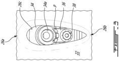
- Fig. 3 it can be seen that the socket 34a and the fastener 38 are spaced from one another respectively toward the leading edge 26a and the trailing edge 26b of the strut 26.
- An inner surface 26c of the strut 26 surrounding the socket 34a bulges as it nears the leading edge 26a, and narrows as it nears the trailing edge 26b.
- the locking member 36 is sized to fit inward of the inner surface 26c on a side of the socket 34a facing toward the trailing edge 26b.
- the pawl P is located on the side of the socket 34a facing toward the trailing edge 26b.
- the hub H includes a plurality of hub teeth H T located radially outward of a shank 32c of the service tube 32 relative to the tube axis T and spaced circumferentially from one another.
- the hub H is provided in this case with 15 hub teeth H T extending radially outwardly relative to the tube axis T to a respective apex H T a at a 24-degree angle from one another.
- the hub teeth H T are thus spaced from one another by a same hub pitch H P ( Fig. 11 ).
- each hub tooth H T extends from an annular base H T b that extends radially outward from the shank 32c.
- Each hub tooth H T defines a first side H T 1 and a second side H T 2 meeting at a corresponding apex H T a.
- the first side H T 1 extends away from the apex H T a toward the shank 32c and also circumferentially in a first circumferential direction, or first handedness, R1.
- the second side H T 2 extends toward the shank 32c so as to generally face toward a second circumferential direction, or handedness, R2 opposite to the first handedness R1.
- the second side H T 2 may also extend circumferentially in the second handedness R2, in which case a circumferential dimension of the second side H T 2 is smaller than that of the first side H T 1.
- the first side H T 1 may thus be said to extend toward the shank 32c more gradually than the second side H T 2.
- rotational impingement of the hub H with an object projecting between two consecutive hub teeth H T may be said to be more lenient in the first handedness R1 and more aggressive in the second handedness R2.
- the service tube 32 is arranged such that the first handedness R1 corresponds to a tightening direction of the threaded end portion 32b, i.e., a direction suitable for threadably engaging the threaded end portion 32b with the socket 34a.
- the hub teeth H T can be shaped and/or sized differently, and/or provided in different amounts.
- the locking member 36 has a cantilever 36c that extends from a fixed end 36c' that is held relative to the mating part 34, in this case via the base 36a, to a free end 36c".
- the cantilever 36c extends linearly and generally parallel to the socket axis S, although various other shapes are possible.
- the ratchet pawl P is located at the free end 36c", and may thus be said to be cantilevered relative to the mating part 34. As will be described in greater detail hereinbelow, the pawl P is held in a resting position P R ( Figs.
- the cantilever 36c is resiliently deformable so as to reversibly deflect radially outwardly at its free end 36" relative to the socket axis S, allowing the pawl P to be urged outwardly into a deflected position P D ( Fig. 9 ) under a radial force, and biasing the pawl P back toward the resting position P R upon the radial force being withdrawn.
- the pawl P is cooperable with the hub H such that upon the pawl P being engaged with the hub H ( Figs.
- the service tube 32 is shown in a seated position relative to the mating part 34, in which the tip 34a is bottomed out in the socket 34a, in this case having reached the sealing surface 34c.
- the service tube 32, the mating part 34 and the locking member 36 are structured and arranged relative to one another such that upon the service tube 32 being in the seated position, the pawl P is engaged with the hub H.
- the service tube 32 is shown aligned with the socket 34a such that the tube and the socket axes T, S are colinear, with the tip 32a aligned with the outer surface 34b just outside of the socket 34a.
- the pawl P may be in the resting position P R or in a partially-deflected position between the resting position P R and the deflected position P D .
- the service tube 32 is still aligned with the socket 34a such that the tube and the socket axes T, S are colinear, the tip 32a is now received by the socket 34a and the threaded end portion 32b is threadably engaged with the socket 34a, albeit partially, e.g, by an amount sufficient for the engagement between the socket 34a and the threaded end portion 32b to align the tube axis T with the socket axis S, for example one turn.
- the pawl P is located between the threaded end portion 32b and the hub H.
- the service tube 32, the mating part 34 and the locking member 36 are structured and arranged relative to one another such that the service tube 32 is partially engageable with the mating part 34 without the pawl P being engaged with the hub H.
- the pawl P is engageable with the hub H upon the service tube 32 having been engaged with the mating part 34.
- the hub H nears the pawl P and eventually engages therewith.
- the service tube 32 may be provided with a shoulder 32d disposed between the threaded end portion 32b and the hub H.
- the shoulder 32d is an annular bulge of the service tube 32 that extends radially outward relative to the shank 32c and is sized such that the pawl P is urged outwardly, i.e., away from the resting position P R and toward the deflected position P D upon the pawl P engaging with the shoulder 32d as the hub H nears the pawl P.
- Either one or both of the shoulder 32d and the pawl P may have a leading surface allowing to induce a radial movement of the pawl P relative to the shoulder 32d as the shoulder 32d axially engages the pawl P.
- the shoulder 32d may include a shoulder leading surface 32e that flares as it extends toward the hub H.
- the shoulder leading surface 32e converges toward the tube axis T as it extends away from the hub H and toward the threaded end portion 32b.
- the pawl P may be defined by a pad-like projection 36d extending radially relative to the free end 36c" of the cantilever 36c toward the socket axis S.
- the projection 36d has a top side (i.e., a side facing away from the fixed end 36c' of the cantilever 36c) which may include a pawl leading surface 36e, for instance a chamfer.
- the projection 36d also has a bottom side (i.e., a side facing toward the fixed end 36c') that may extend to radially inward of a periphery of the shoulder 32d upon the service tube 32 being in the seated position.
- the pawl P is disposed radially outward of the socket axis S, and includes at least one pawl tooth P T facing generally inwardly relative to the socket axis S.
- the at least one pawl tooth P T is a ridge-like formation located onto the projection 36d and extending from the top side to the bottom side.
- the projection 36d could be omitted, and the at least one pawl tooth P T could instead be located on the free end 36c" of the cantilever 36c.
- Each pawl tooth P T defines a first side P T1 and a second side P T2 meeting at a corresponding apex P T a.
- the second side P T2 extends away from the apex P T a toward the projection 36d and also circumferentially in the second handedness R2.
- the first side P T1 extends toward the projection 36d so as to generally face toward the first handedness R1.
- the first side P T1 may also extend circumferentially in the first handedness R1, in which case a circumferential dimension of the first side P T1 is smaller than that of the second side P T2 .
- the second side P T2 may thus be said to extend toward the projection 36d more gradually than the first side P T1 .
- the first side P T1 of the at least one pawl tooth P T and the second side H T2 of the hub teeth H T may be complementarily shaped to achieve a desired degree of anti-rotational engagement.
- the service tube 32 may be driven in the first handedness R1 into the socket 34a such that the tip 32a compresses the sealing surface 34c to achieve a desired sealing effect.
- a suitable magnitude of compression can be achieved by using a torquing device to apply a torque of a nominal torque value on the service tube 32 about the tube axis T in the first handedness R1.
- the locking device 36 is adapted to hold the service tube 32 in place via anti-rotational engagement of the pawl P relative to the hub H, despite the service tube 32 exerting a reaction torque of a corresponding value in the second handedness R2.
- the pawl P is structured and arranged such that the at least one pawl tooth P T is capable of withstanding an engagement force E imparted thereon via a given hub tooth (hereinafter “first hub tooth H TI ”) of the hub teeth H T , the engagement force E having a magnitude and orientation consistent with the reaction torque.
- first hub tooth H TI a given hub tooth of the hub teeth H T
- the apex H T a of the first hub tooth H TI is located at a nominal angular position ⁇ .
- the pawl P is arranged such that the at least one pawl tooth P T is engageable with the first hub tooth H TI upon the first hub tooth H TI having reached at least the nominal angular position ⁇ in the first handedness R1.
- the at least one pawl tooth P T may thus be located either at the nominal angular position, or past the nominal angular position ⁇ in the first handedness R1, in which case it follows that the first hub tooth H TI must be displaced past the nominal angular position ⁇ in order to be engageable with the at least one pawl tooth P T .
- a torque of a rated installation torque value greater than the nominal torque value may be applied on the service tube 32 in order to displace the first hub tooth H TI in the first handedness R1 past the at least one pawl tooth P T , for the first hub tooth H TI to engage with the at least one pawl tooth P T upon release of the service tube 32 from the torquing device.
- the reaction torque may thus increase up to a value corresponding to the rated installation torque value, and may decrease until engagement of the first hub tooth H TI in case of backlash.
- the first hub tooth H TI has to travel back across the distance ⁇ before it engages with the at least one pawl tooth P T .
- backlash may occur as a result of a spring back effect at the interface between the service tube 32 and the socket 34a, for example between the sealing surface 34c and the tip 32a.
- the at least one pawl tooth P T is frangible by the first hub tooth H TI in the second handedness R2 upon a torque exerted onto the service tube 32 in the second handedness R2 being of a rated release torque value that is greater than the rated installation torque value. Stated otherwise, the anti-rotational engagement of the pawl P and the hub H is overcomable upon applying a torque of the rated release torque value to the service tube 32 in the second handedness R2.
- the service tube 32 and the locking member 36 may be respectively constructed of a first and a second material, the second material having a rigidity that is less than that of the first material. By this arrangement, the integrity of the hub H is promoted over that of the locking member 36.
- the pawl P may have a plurality of pawl teeth P T that are circumferentially spaced from one another.
- the pawl P may be adapted to engage with the hub H upon the first hub tooth H TI being in at least one angular position other than the nominal angular position ⁇ .
- the first pawl tooth P TI and the second pawl tooth P TII are spaced from one another by a pawl pitch (i.e., a first pawl pitch P PI ) that may be smaller than the hub pitch H P .
- a pawl pitch i.e., a first pawl pitch P PI
- the first hub tooth H TI would be displaced past the first pawl tooth P TI , and the resulting backlash would be limited to a lesser distance as the first pawl tooth P TI would engage the first hub tooth H TI upon release of the service tube 32 from the torquing device.
- the pawl P has seven pawl teeth P TI , P TII , P TIII , P TIV , P TV , P TVI , P TVII spaced circumferentially and consecutively in the second handedness R2.
- the second pawl tooth P TII is spaced from the first pawl tooth P TI by the first pawl pitch P PI .
- the third pawl tooth P TIII is spaced from the second pawl tooth P TII by a second pawl pitch P PII .
- the fourth pawl tooth P TVI is spaced from the third pawl tooth P TIII by a third pawl pitch P PIII .
- the fifth pawl tooth P TV is spaced from the fourth pawl tooth P TIV by a fourth pawl pitch P PIV .
- the sixth pawl tooth P TVI is spaced from the fifth pawl tooth P TV by a fifth pawl pitch P PV .
- the seventh pawl tooth P TVII is spaced from the sixth pawl tooth P TVI by a sixth pawl pitch P PVI .
- the first pawl pitch P PI is less than the second pawl pitch P PII and the sixth pawl pitch P PVI , but is greater than the third P PIII , fourth P PVI and fifth P PV pawl pitches. Other arrangements are possible.
- the pawl teeth P T are spaced from one another by a pawl pitch corresponding to the hub pitch H P . This arrangement may allow to distribute the engagement force E on the corresponding pawl teeth P T .
- the pawl teeth P T are spaced from one another such that the hub H is engageable with the pawl P via a sole hub tooth H T regardless of the angular position of the service tube 32.
- the pawl P is formed of a plurality of pawl sectors P S1 , P S2 , P S3 each having one or more of the pawl teeth P T .
- a first pawl sector P S1 has the first and second pawl teeth P TI , P TII .
- a second pawl sector P S2 has the third, fourth and fifth pawl teeth P TIII , P TIV , P TV .
- a third pawl sector P S3 has the sixth and seventh pawl teeth P TVI , P TVII .
- the locking member 36 is provided with a plurality of individual cantilevers 36c (which may be referred to as fingers together forming the cantilever 36c) extending side by side from the base 36a.
- the pawl sectors P S1 , P S2 , P S3 are respectively located at the free end 36" of a corresponding one of the cantilevers 36c.
- the locking member 36 is arranged such that the pawl sectors P S1 , P S2 , P S3 maintain contact with the hub H regardless of the angular position of the service tube 32. This arrangement may mitigate dynamic issues such as wear-inducing vibration at the interface between the pawl P and the hub H.
- a given pawl tooth P T e.g.
- the second pawl tooth P TII is anti-rotationally engaged with a given hub tooth H T
- a corresponding pawl sector P S1 , P S2 , P S3 e.g., the first pawl sector P S1
- a remainder of the pawl sectors P S1 , P S2 , P S3 e.g., the second and third pawl sectors P S2 , P S3
- all of the pawl sectors P S1 , P S2 , P S3 may be urged by the hub H away from the resting position P R regardless of the angular position of the service tube 32.
- a locking member 36 that is provided with a pair of individual cantilevers 36c (or fingers) each terminating into a pawl sector P S1 , P S2 .
- Each pawl sector P S1 , P S2 has two pawl teeth P T .
- a locking member 36 that has a pair of individual cantilevers 36c respectively terminating into opposite ends P', P" of an integral pawl P (i.e., a pawl P having a sole sector).
- the pawl P is provided with four pawl teeth P T .
- a locking member 36 that has a sole cantilever 36c terminating into an integral pawl P. From the free end 26c" of the cantilever 36c, the pawl P extends arcuately in the first handedness R1 to its first end P', and in the second handedness R2 to its second end P".
- a locking member 36 that has a sole cantilever 36c terminating into an integral pawl P at one of its ends P', P".
- the pawl P extends arcuately in the second handedness R2 from its first end P' supported by the cantilever 36c to its second end P" that is free relative to the cantilever 36c. It is contemplated that in other embodiments, the second end P" could be supported by the cantilever 36c, whereas the first end P' could be free relative to the cantilever 36c.
- All of the above described alternative embodiments provide for a method of assembling a service tube to an engine component, wherein the method comprises: threadably engaging the service tube with a socket of the engine component, including rotating the service tube in a first handedness relative to the engine component; and locking the service tube against rotation in a second handedness opposite the first handedness relative to the engine component, including catching a ratchet hub of the service tube with a ratchet pawl cantilevered with respect to the engine component away from the socket.
- the threadably engaging of the service tube can include applying a torque to the service tube corresponding to a rated installation torque value to ratchet the ratchet hub across a pawl tooth of the ratchet pawl.
- the threadably engaging of the service tube can include biasing the ratchet pawl away from a longitudinal axis of the service tube before the locking of the service tube.
- the method can also comprise fastening the ratchet pawl relative to the engine component prior to the threadably engaging of the service tube with the socket.
- the service tube has been described as a service tube for providing oil to a bearing, it is understood that the service tube could be mounted to other engine components or mating parts.
- the service tube may be used to transport air or oil from between a sump and an external conduit, such as an oil supply or scavenge line, or sump pressurization or vent line.
- an oil supply or scavenge line or sump pressurization or vent line.
- a wide variety of mechanical fasteners may be used to suitably secure the locking member against the mating part.
- Yet further modifications could be implemented by a person of ordinary skill in the art in view of the present disclosure, which modifications would be within the scope of the present technology.
Landscapes
- Engineering & Computer Science (AREA)
- General Engineering & Computer Science (AREA)
- Mechanical Engineering (AREA)
- Physics & Mathematics (AREA)
- Fluid Mechanics (AREA)
- Mutual Connection Of Rods And Tubes (AREA)
- Quick-Acting Or Multi-Walled Pipe Joints (AREA)
Abstract
Description
- The application relates generally to service tubes and, more particularly, to service tube assemblies.
- Turbine engines include various pipes or tubes therein for directing air, fuel, oil or mixtures thereof to engine components. Threaded connections are often used between such tubes and the associated engine components. However, threaded connections are susceptible to loosening after assembly due to various factors, such as vibrations, impacts, or alternating thermal loads to name a few.
- In accordance with one aspect, there is provided a service tube assembly for an aircraft engine, comprising: a service tube having a threaded end portion and a ratchet hub spaced from the threaded end portion; a mating part having a socket threadably engaged with the threaded end portion of the service tube; and a locking member having a cantilever extending from a fixed end held relative to the mating part proximate to the socket to a free end spaced away from the socket, and a ratchet pawl located at the free end, the ratchet pawl anti-rotationally engaged with the ratchet hub.
- In accordance with another aspect, there is provided a turbine exhaust case comprising: an outer duct wall and an inner duct wall defining therebetween an annular gas path about an engine axis; a strut extending across the annular gas path; a service tube extending through the strut, the service tube having a threaded inner end portion and a ratchet hub spaced from the threaded inner end portion; a bearing housing disposed radially inwardly from the inner duct wall, the bearing housing having a socket, the threaded inner end portion of the service tube threadably engaged with the socket, the bearing housing further having a seat located next to the socket; a locking member having a base disposed on the seat, a cantilever extending from a fixed end fixed relative to the base to a free end spaced away from the base, and a ratchet pawl located at the free end, the ratchet pawl anti-rotationally engaged with the ratchet hub; and a threaded fastener releasably holding the base against the seat.
- In accordance with a further aspect, there is provided a method of assembling a service tube to an engine component, the method comprising: threadably engaging the service tube with a socket of the engine component, including rotating the service tube in a first handedness relative to the engine component; and locking the service tube against rotation in a second handedness opposite the first handedness relative to the engine component, including catching a ratchet hub of the service tube with a ratchet pawl cantilevered with respect to the engine component away from the socket.
- The following optional features may be applied to any of the above aspects and to any of the embodiments of the dependent claims (as long as they are not inconsistent therewith):
- Optionally, and in accordance with any of the above, the cantilever is formed of a plurality of fingers.
- Optionally, and in accordance with any of the above, the ratchet pawl extends arcuately away from the free end of the cantilever.
- Optionally, and in accordance with any of the above, the ratchet pawl is located radially between the threaded fastener and the inner duct wall relative to the engine axis.
- Optionally, and in accordance with any of the above, the strut has a leading edge and a trailing edge opposite to the leading edge, the socket and the threaded fastener spaced from one another respectively toward the leading edge and the trailing edge.
- Optionally, and in accordance with any of the above, the ratchet pawl is located on a side of the socket facing toward the trailing edge.
- Reference is now made to the accompanying figures in which:
-
Fig. 1 is a schematic cross section view of a gas turbine engine; -
Fig. 2 is a schematic cross-section view of a turbine exhaust case of the engine shown inFig. 1 including a service tube assembly according to an embodiment; -
Fig. 3 is a close-up view of a service tube assembly of the turbine exhaust case shown inFig. 3 shown from across a stud of the turbine exhaust case, with a service tube removed from a remainder of the service tube assembly; -
Fig. 4 is an isometric view of the remainder of the service tube assembly; -
Fig. 5 is an exploded view of a locking member and of a mating part of the service tube assembly; -
Fig. 6 is a cross-section view of the service tube assembly; -
Fig. 7 is an elevation view of the service tube assembly, shown with the service tube in a pre-engagement position relative to the mating part and to the locking member; -
Fig. 8 is a cross-section view of the service tube assembly, shown with the service tube engaged relative to the mating part and disengaged relative to the locking member; -
Fig. 9 is a close-up view of a ratchet pawl of the locking member shown biased outwardly by a shoulder of the service tube; -
Fig. 10 is a perspective view of the service tube assembly, shown with the service tube engaged relative to the mating part and engaged relative to the locking member; -
Fig. 11 is a top planar view of the service tube assembly ofFig. 10 ; -
Fig. 12 is a close-up view of a ratchet hub of the service tube assembly shown engaged with the ratchet pawl; -
Fig. 13 is an isometric view of a locking member of a service tube assembly according to another embodiment; -
Fig. 14 is an isometric view of a locking member of a service tube assembly according to another embodiment; -
Fig. 15 is a perspective view of a locking member of a service tube assembly according to a further embodiment; and -
Fig. 16 is a perspective view of a locking member of a service tube assembly according to a still further embodiment. - The description is generally directed to systems, methods, and other devices related to routing fluid flow (e.g. air, oil, fuel or mixtures thereof) in an engine and, more particularly, to systems, methods and devices for securing a threaded connection between a service tube and an associated engine component or mating part. The mating part can be any feature(s) configured for connection to a service tube. For purposes of illustration, the technology will be described with respect to an aircraft gas turbine engine. It will be understood, however, that the technology is not so limited and may have general applicability in non-aircraft applications, such as other mobile applications and non-mobile industrial, commercial, and residential applications, including power generation. Furthermore, even though the following description and accompanying drawings specifically refer to an Auxiliary Power Unit (APU) as an example, it is understood that aspects of the present disclosure may be equally applicable to a wide variety of engines including all types of gas turbine (e.g., continuous combustion) engines, internal (e.g., intermittent) combustion engines, electric powerplants and hybrid powerplants to name a few. It should be further understood that while a particular embodiment is described in reference to a service tube within a strut of a turbine exhaust case, the features of the exemplified service tube assembly could be applied to other service tube assemblies within the engine or along the engine case.
- The term "service tube" is herein intended to encompass any tube that can be used in an engine to route a fluid, such as air, oil, air/oil mixture, etc. to an engine component.
- The terms "attached", "coupled", "connected" or "engaged" may include both direct attachment, coupling, connection or engagement (in which two components contact each other) and indirect attachment, coupling, connection or engagement (in which at least one additional component is located between the two components).
- The terms "substantially" and "generally" as used herein may be applied to modify any quantitative representation which could permissibly vary without resulting in a change in the basic function to which it is related.
- Aspects of various embodiments will now be described through reference to the drawings.
-
Fig. 1 illustrates agas turbine engine 10 suitable for use as an APU and generally comprising in serial flow communication anair inlet 11, acompressor 12 for pressurizing the air from theair inlet 11, acombustor 13 in which the compressed air is mixed with fuel and ignited for generating an annular stream of hot combustion gases, aturbine 14 for extracting energy from the combustion gases, and anexhaust 15 through which the combustion gases exit theengine 10. According to the illustrated exemplary engine, theturbine 14 is drivingly connected to an input end of a reduction gearbox (RGB) 16. TheRGB 16 has an output end drivingly connected to anoutput shaft 18 configured to drive a rotatable load, such as a generator (not shown). - Turning to
Fig. 2 , it can be seen that theexhaust 15 comprises aturbine exhaust case 20 having anouter duct wall 22 and aninner duct wall 24 defining therebetween an annular gas path G extending about an engine axis A. Theexhaust case 20 further comprises a plurality ofstruts 26 circumferentially interspaced from one another and extending generally radially across the annular gas path G from theouter duct wall 22 to theinner duct wall 24, thereby structurally interconnecting the outer andinner duct walls struts 26 can have an airfoil profile for directing the exhaust gases received from theturbine 14. The struts can thus have a leadingedge 26a and atrailing edge 26b. Aservice tube assembly 30 can be disposed in a hollow interior of one or more of thestruts 26 for feeding a service fluid, such as air, oil or an oil/air medium, to an engine component disposed radially inwardly of the gas path G. According to the illustrated embodiment, theservice tube assembly 30 is used to provide oil to a bearing 28 mounted inside theexhaust case 15 for supporting an aft end of a main rotor of the engine 10 (e.g. the aft end of a low pressure spool). - Referring jointly to
Figs. 2 to 6 , it can be appreciated that theservice tube assembly 30 generally comprises aservice tube 32 and amating part 34, herein provided in the form of a bearing housing supporting thebearing 28. Theservice tube 32 has atip 32a and a threadedend portion 32b located proximate to thetip 32a and threadedly engaged in a corresponding threadedbore 34a (hereinafter "socket" 34a) defined in anouter surface 34b of themating part 34. Thesocket 34a may be a straight-walled bore provided with a suitable threaded insert. Theservice tube 32 is tightened to a predetermined torque to compress thetip 32a in sealing engagement with a corresponding sealing surface 34c circumscribing an inner end portion of the threadedbore 34a in themating part 34. In certain implementations, a seal may be placed between thetip 32a and the sealing surface 34c. Thesocket 34a extends circumferentially about a socket axis S, and engagement of the threadedend portion 32b with thesocket 34a causes theservice tube 32 to align with the socket axis S. Over time, such a threaded connection may become loose, which may result in oil leakage at theservice tube 32 and matingpart 34 interface. - It is herein proposed to provide the
service tube assembly 30 with an anti-loosening or locking structure to hold theservice tube 32 in place after the same has been fastened to a specified torque. The anti-loosening structure generally comprises alocking member 36 interfacing between theservice tube 32 and themating part 34 at a location near the threaded engagement therebetween to lock theservice tube 32 insofar as rotational loosening relative to themating part 34 is prevented. As will be described in greater detail hereinbelow, theservice tube 32 and thelocking member 36 are respectively provided with a ratchet hub H and a ratchet pawl P that are engageable with one another such that rotation of theservice tube 32 about the socket axis S is allowed in a first direction, and hindered in a second direction opposite to the first direction. As best seen inFig. 2 , the hub H (when the threadedend portion 32b of theservice tube 32 is engaged with thesocket 34a) and the pawl P are located proximate to themating part 34 and in particular radially inward of theinner duct wall 24 of theexhaust case 20 relative to the axis A. By this arrangement, the anti-loosening structure is spaced, and thus thermally-insulated, from annular gas path G and its associated high-temperature conditions, rendering the hub H and the pawl P sufficiently dimensionally stable, which may desirably affect the reliability of their engagement. - Depending on the embodiment, the anti-loosening structure of the
service tube assembly 30 may also comprise afastener 38 releasably holding thelocking member 36 against themating part 34, as is the case in the illustrated exemplary embodiments. Indeed, although it is contemplated that thelocking member 36 could be integral to themating part 34 or be permanently affixed thereto, thelocking member 36 can advantageously be fastened to themating part 34 so as to be easily removable from themating part 34 to facilitate removal of theservice tube 32 from themating part 34 or for replacement of thelocking member 36 in case of wear that may affect the reliability of the engagement. The lockingmember 36 thus has abase 36a adapted to be seated onto themating part 34 and defining abore 36b adapted to receive thefastener 38. The engagement between the lockingmember 36 and themating part 34 may be located radially outward of the engagement between the lockingmember 36 and theservice tube 32 relative to the axis A. The pawl P may thus be located radially between thefastener 38 and theinner duct wall 24 relative to the axis A. Thebase 36a may for example have a shape complementary to a shape of aseat 34d defined by theouter surface 34b of themating part 34 proximate to thesocket 34a. Theseat 34d may have a threadedbore 34e located so as to be aligned with thebore 36b of thebase 36a upon thebase 36a being received by theseat 34d. The threadedbore 34e may instead be a straight-walled bore provided with a threaded insert of a suitable type, for example a helicoil insert. In some exemplary arrangements, an underside of thebase 36a defines a footprint that may be fully received by theseat 34d. Alternatively, as seen inFig. 5 , the footprint of thebase 36a may include a plug-like projection 36a' that is offset from a remainder of the footprint. Theprojection 36a' may thus define the shape suitable for being received by theseat 34d, whereas the remainder of the footprint of thebase 36a may rest against theouter surface 34b of themating part 34. In embodiments, the respective complementary shapes of thebase 36a and theseat 34d are arranged such that a sole position of the lockingmember 36 relative to themating part 34 is possible, i.e., the lockingmember 36 and themating part 34 are indexed relative to one another via thebase 36a and theseat 34d. For this purpose, thebase 36a may be provided with a locatingpin 36a", for example underneath theprojection 36a', to be received in a complementarilysized recess 34d' of themating part 34, provided for example in theseat 34d. This arrangement can also be described as being anti-rotational, as the respective complementary shapes of thebase 36a and theseat 34d hinder angular movement of the lockingmember 36 relative to themating part 34, for example about the socket axis S and/or about a fastener socket axis F despite torque being exerted onto the lockingmember 36 via theservice tube 32 as theservice tube 32 is rotationally driven into thesocket 34a or rotationally springs back therefrom. - As best seen in
Fig. 2 , theservice tube 32 extends longitudinally along a tube axis T from a proximal end 32', i.e., an end defining thetip 32a and the threadedend portion 32b and thus configured to be disposed closest to themating part 34, to adistal end 32" opposite to the proximal end 32'. Thedistal end 32" is adapted to be operatively connected to a torquing device via which torque can be applied to theservice tube 32 to rotate the same about the tube axis T, for example in a direction suitable for threadably engaging the threadedend portion 32b. The hub H is spaced from the threadedend portion 32b in a direction away from thetip 32a, yet is located closer to thetip 32a than to thedistal end 32". In embodiments, the hub H is located between thetip 32a and an axial center of theservice tube 32 along the tube axis T, and is closer to thetip 32a than to the axial center, such that the hub H can be said to be part of the proximal end 32'. - In
Fig. 3 , it can be seen that thesocket 34a and thefastener 38 are spaced from one another respectively toward theleading edge 26a and the trailingedge 26b of thestrut 26. Aninner surface 26c of thestrut 26 surrounding thesocket 34a bulges as it nears theleading edge 26a, and narrows as it nears the trailingedge 26b. The lockingmember 36 is sized to fit inward of theinner surface 26c on a side of thesocket 34a facing toward the trailingedge 26b. Hence, the pawl P is located on the side of thesocket 34a facing toward the trailingedge 26b. - Reference will now be generally made to
Figs. 6 to 12 in which an exemplary hub H and pawl P arrangement is shown in greater detail. The hub H includes a plurality of hub teeth HT located radially outward of ashank 32c of theservice tube 32 relative to the tube axis T and spaced circumferentially from one another. As best seen inFig. 11 , the hub H is provided in this case with 15 hub teeth HT extending radially outwardly relative to the tube axis T to a respective apex HTa at a 24-degree angle from one another. The hub teeth HT are thus spaced from one another by a same hub pitch HP (Fig. 11 ). In this embodiment, each hub tooth HT extends from an annular base HTb that extends radially outward from theshank 32c. Each hub tooth HT defines a first side HT1 and a second side HT2 meeting at a corresponding apex HTa. The first side HT1 extends away from the apex HTa toward theshank 32c and also circumferentially in a first circumferential direction, or first handedness, R1. The second side HT2 extends toward theshank 32c so as to generally face toward a second circumferential direction, or handedness, R2 opposite to the first handedness R1. The second side HT2 may also extend circumferentially in the second handedness R2, in which case a circumferential dimension of the second side HT2 is smaller than that of the first side HT1. The first side HT1 may thus be said to extend toward theshank 32c more gradually than the second side HT2. As such, rotational impingement of the hub H with an object projecting between two consecutive hub teeth HT may be said to be more lenient in the first handedness R1 and more aggressive in the second handedness R2. Also, it should be noted that theservice tube 32 is arranged such that the first handedness R1 corresponds to a tightening direction of the threadedend portion 32b, i.e., a direction suitable for threadably engaging the threadedend portion 32b with thesocket 34a. In other embodiments, the hub teeth HT can be shaped and/or sized differently, and/or provided in different amounts. - The locking
member 36 will now be described in more detail. The lockingmember 36 has acantilever 36c that extends from afixed end 36c' that is held relative to themating part 34, in this case via thebase 36a, to afree end 36c". In this embodiment, thecantilever 36c extends linearly and generally parallel to the socket axis S, although various other shapes are possible. The ratchet pawl P is located at thefree end 36c", and may thus be said to be cantilevered relative to themating part 34. As will be described in greater detail hereinbelow, the pawl P is held in a resting position PR (Figs. 7 ,8 ) radially outward of the socket axis S by thecantilever 36c absent any load exerted onto the pawl P. Thecantilever 36c is resiliently deformable so as to reversibly deflect radially outwardly at itsfree end 36" relative to the socket axis S, allowing the pawl P to be urged outwardly into a deflected position PD (Fig. 9 ) under a radial force, and biasing the pawl P back toward the resting position PR upon the radial force being withdrawn. The pawl P is cooperable with the hub H such that upon the pawl P being engaged with the hub H (Figs. 6 ,10-12 ), rotation of theservice tube 32 relative to themating part 34 in the first handedness R1 is allowed by the pawl P, whereas rotation of theservice tube 32 relative to themating part 34 in the second handedness R2 is hindered by the pawl P. - In
Fig. 6 , theservice tube 32 is shown in a seated position relative to themating part 34, in which thetip 34a is bottomed out in thesocket 34a, in this case having reached the sealing surface 34c. Theservice tube 32, themating part 34 and the lockingmember 36 are structured and arranged relative to one another such that upon theservice tube 32 being in the seated position, the pawl P is engaged with the hub H. InFig. 7 , theservice tube 32 is shown aligned with thesocket 34a such that the tube and the socket axes T, S are colinear, with thetip 32a aligned with theouter surface 34b just outside of thesocket 34a. In this position of theservice tube 32, the pawl P may be in the resting position PR or in a partially-deflected position between the resting position PR and the deflected position PD. InFig. 8 , theservice tube 32 is still aligned with thesocket 34a such that the tube and the socket axes T, S are colinear, thetip 32a is now received by thesocket 34a and the threadedend portion 32b is threadably engaged with thesocket 34a, albeit partially, e.g, by an amount sufficient for the engagement between thesocket 34a and the threadedend portion 32b to align the tube axis T with the socket axis S, for example one turn. In this position of theservice tube 32, the pawl P is located between the threadedend portion 32b and the hub H. Hence, theservice tube 32, themating part 34 and the lockingmember 36 are structured and arranged relative to one another such that theservice tube 32 is partially engageable with themating part 34 without the pawl P being engaged with the hub H. Stated otherwise, the pawl P is engageable with the hub H upon theservice tube 32 having been engaged with themating part 34. As thetip 32a progresses into thesocket 34a, the hub H nears the pawl P and eventually engages therewith. Still referring toFig. 8 , theservice tube 32 may be provided with ashoulder 32d disposed between the threadedend portion 32b and the hub H. Theshoulder 32d is an annular bulge of theservice tube 32 that extends radially outward relative to theshank 32c and is sized such that the pawl P is urged outwardly, i.e., away from the resting position PR and toward the deflected position PD upon the pawl P engaging with theshoulder 32d as the hub H nears the pawl P. Either one or both of theshoulder 32d and the pawl P may have a leading surface allowing to induce a radial movement of the pawl P relative to theshoulder 32d as theshoulder 32d axially engages the pawl P. Theshoulder 32d may include ashoulder leading surface 32e that flares as it extends toward the hub H. Stated otherwise, theshoulder leading surface 32e converges toward the tube axis T as it extends away from the hub H and toward the threadedend portion 32b. The pawl P may be defined by a pad-like projection 36d extending radially relative to thefree end 36c" of thecantilever 36c toward the socket axis S. The projection 36d has a top side (i.e., a side facing away from thefixed end 36c' of thecantilever 36c) which may include apawl leading surface 36e, for instance a chamfer. The projection 36d also has a bottom side (i.e., a side facing toward thefixed end 36c') that may extend to radially inward of a periphery of theshoulder 32d upon theservice tube 32 being in the seated position. - As best seen in
Fig. 11 , the pawl P is disposed radially outward of the socket axis S, and includes at least one pawl tooth PT facing generally inwardly relative to the socket axis S. In the depicted embodiments, the at least one pawl tooth PT is a ridge-like formation located onto the projection 36d and extending from the top side to the bottom side. In alternate embodiments, the projection 36d could be omitted, and the at least one pawl tooth PT could instead be located on thefree end 36c" of thecantilever 36c. Each pawl tooth PT defines a first side PT1 and a second side PT2 meeting at a corresponding apex PTa. The second side PT2 extends away from the apex PTa toward the projection 36d and also circumferentially in the second handedness R2. The first side PT1 extends toward the projection 36d so as to generally face toward the first handedness R1. The first side PT1 may also extend circumferentially in the first handedness R1, in which case a circumferential dimension of the first side PT1 is smaller than that of the second side PT2. The second side PT2 may thus be said to extend toward the projection 36d more gradually than the first side PT1. The first side PT1 of the at least one pawl tooth PT and the second side HT2 of the hub teeth HT may be complementarily shaped to achieve a desired degree of anti-rotational engagement. - During the installation of the
service tube 32, theservice tube 32 may be driven in the first handedness R1 into thesocket 34a such that thetip 32a compresses the sealing surface 34c to achieve a desired sealing effect. With thetip 32a being adjacent to the sealing surface 34c, a suitable magnitude of compression can be achieved by using a torquing device to apply a torque of a nominal torque value on theservice tube 32 about the tube axis T in the first handedness R1. To maintain such compression in absence of the torquing device, the lockingdevice 36 is adapted to hold theservice tube 32 in place via anti-rotational engagement of the pawl P relative to the hub H, despite theservice tube 32 exerting a reaction torque of a corresponding value in the second handedness R2. For this purpose, the pawl P is structured and arranged such that the at least one pawl tooth PT is capable of withstanding an engagement force E imparted thereon via a given hub tooth (hereinafter "first hub tooth HTI") of the hub teeth HT, the engagement force E having a magnitude and orientation consistent with the reaction torque. - Referring to
Fig. 12 , upon the suitable magnitude of compression being achieved, the apex HTa of the first hub tooth HTI is located at a nominal angular position α. The pawl P is arranged such that the at least one pawl tooth PT is engageable with the first hub tooth HTI upon the first hub tooth HTI having reached at least the nominal angular position α in the first handedness R1. The at least one pawl tooth PT may thus be located either at the nominal angular position, or past the nominal angular position α in the first handedness R1, in which case it follows that the first hub tooth HTI must be displaced past the nominal angular position α in order to be engageable with the at least one pawl tooth PT. A torque of a rated installation torque value greater than the nominal torque value may be applied on theservice tube 32 in order to displace the first hub tooth HTI in the first handedness R1 past the at least one pawl tooth PT, for the first hub tooth HTI to engage with the at least one pawl tooth PT upon release of theservice tube 32 from the torquing device. The reaction torque may thus increase up to a value corresponding to the rated installation torque value, and may decrease until engagement of the first hub tooth HTI in case of backlash. Indeed, if the applied torque causes the first hub tooth HTI to be displaced by a distance δ past the angular position of the at least one pawl tooth PT, the first hub tooth HTI has to travel back across the distance δ before it engages with the at least one pawl tooth PT. Such backlash may occur as a result of a spring back effect at the interface between theservice tube 32 and thesocket 34a, for example between the sealing surface 34c and thetip 32a. - In embodiments, the at least one pawl tooth PT is frangible by the first hub tooth HTI in the second handedness R2 upon a torque exerted onto the
service tube 32 in the second handedness R2 being of a rated release torque value that is greater than the rated installation torque value. Stated otherwise, the anti-rotational engagement of the pawl P and the hub H is overcomable upon applying a torque of the rated release torque value to theservice tube 32 in the second handedness R2. Theservice tube 32 and the lockingmember 36 may be respectively constructed of a first and a second material, the second material having a rigidity that is less than that of the first material. By this arrangement, the integrity of the hub H is promoted over that of the lockingmember 36. - The pawl P may have a plurality of pawl teeth PT that are circumferentially spaced from one another. By providing the pawl P with at least another pawl tooth PT (i.e., a first pawl tooth PTI) in addition to the at least one pawl tooth PT (i.e., a second pawl tooth PTII), the pawl P may be adapted to engage with the hub H upon the first hub tooth HTI being in at least one angular position other than the nominal angular position α. The first pawl tooth PTI and the second pawl tooth PTII are spaced from one another by a pawl pitch (i.e., a first pawl pitch PPI) that may be smaller than the hub pitch HP. In such case, should the applied torque cause the first hub tooth HTI to be displaced past the angular position of the second pawl tooth PTII by a distance greater than the first pawl pitch PPI (e.g., a distance corresponding to the hub pitch HP), the first hub tooth HTI would be displaced past the first pawl tooth PTI, and the resulting backlash would be limited to a lesser distance as the first pawl tooth PTI would engage the first hub tooth HTI upon release of the
service tube 32 from the torquing device. - In this exemplary embodiment, the pawl P has seven pawl teeth PTI, PTII, PTIII, PTIV, PTV, PTVI, PTVII spaced circumferentially and consecutively in the second handedness R2. The second pawl tooth PTII is spaced from the first pawl tooth PTI by the first pawl pitch PPI. The third pawl tooth PTIII is spaced from the second pawl tooth PTII by a second pawl pitch PPII. The fourth pawl tooth PTVI is spaced from the third pawl tooth PTIII by a third pawl pitch PPIII. The fifth pawl tooth PTV is spaced from the fourth pawl tooth PTIV by a fourth pawl pitch PPIV. The sixth pawl tooth PTVI is spaced from the fifth pawl tooth PTV by a fifth pawl pitch PPV. The seventh pawl tooth PTVII is spaced from the sixth pawl tooth PTVI by a sixth pawl pitch PPVI. The first pawl pitch PPI is less than the second pawl pitch PPII and the sixth pawl pitch PPVI, but is greater than the third PPIII, fourth PPVI and fifth PPV pawl pitches. Other arrangements are possible.
- In other embodiments, at least some of the pawl teeth PT are spaced from one another by a pawl pitch corresponding to the hub pitch HP. This arrangement may allow to distribute the engagement force E on the corresponding pawl teeth PT. In this exemplary embodiment, the pawl teeth PT are spaced from one another such that the hub H is engageable with the pawl P via a sole hub tooth HT regardless of the angular position of the
service tube 32. It will also be noted that the pawl P is formed of a plurality of pawl sectors PS1, PS2, PS3 each having one or more of the pawl teeth PT. Namely, a first pawl sector PS1 has the first and second pawl teeth PTI, PTII. A second pawl sector PS2 has the third, fourth and fifth pawl teeth PTIII, PTIV, PTV. A third pawl sector PS3 has the sixth and seventh pawl teeth PTVI, PTVII. The lockingmember 36 is provided with a plurality ofindividual cantilevers 36c (which may be referred to as fingers together forming thecantilever 36c) extending side by side from thebase 36a. The pawl sectors PS1, PS2, PS3 are respectively located at thefree end 36" of a corresponding one of thecantilevers 36c. The lockingmember 36 is arranged such that the pawl sectors PS1, PS2, PS3 maintain contact with the hub H regardless of the angular position of theservice tube 32. This arrangement may mitigate dynamic issues such as wear-inducing vibration at the interface between the pawl P and the hub H. Here, when a given pawl tooth PT (e.g. the second pawl tooth PTII) is anti-rotationally engaged with a given hub tooth HT, a corresponding pawl sector PS1, PS2, PS3 (e.g., the first pawl sector PS1) contacts the hub H from the resting position PR, whereas a remainder of the pawl sectors PS1, PS2, PS3 (e.g., the second and third pawl sectors PS2, PS3) are urged by the hub H away from the resting position PR to respective positions (e.g., PS2', PS3') between the resting position PR and the deflected position PD. In other embodiments, all of the pawl sectors PS1, PS2, PS3 may be urged by the hub H away from the resting position PR regardless of the angular position of theservice tube 32. - With reference to
Figs. 13 to 16 , exemplary alternate embodiments of the lockingmember 36 will now be described. InFig. 13 , there is shown a lockingmember 36 that is provided with a pair ofindividual cantilevers 36c (or fingers) each terminating into a pawl sector PS1, PS2. Each pawl sector PS1, PS2 has two pawl teeth PT. InFig. 14 , there is shown a lockingmember 36 that has a pair ofindividual cantilevers 36c respectively terminating into opposite ends P', P" of an integral pawl P (i.e., a pawl P having a sole sector). The pawl P is provided with four pawl teeth PT. InFig. 15 , there is shown a lockingmember 36 that has asole cantilever 36c terminating into an integral pawl P. From thefree end 26c" of thecantilever 36c, the pawl P extends arcuately in the first handedness R1 to its first end P', and in the second handedness R2 to its second end P". InFig. 16 , there is shown a lockingmember 36 that has asole cantilever 36c terminating into an integral pawl P at one of its ends P', P". In this embodiment, the pawl P extends arcuately in the second handedness R2 from its first end P' supported by thecantilever 36c to its second end P" that is free relative to thecantilever 36c. It is contemplated that in other embodiments, the second end P" could be supported by thecantilever 36c, whereas the first end P' could be free relative to thecantilever 36c. - All of the above described alternative embodiments provide for a method of assembling a service tube to an engine component, wherein the method comprises: threadably engaging the service tube with a socket of the engine component, including rotating the service tube in a first handedness relative to the engine component; and locking the service tube against rotation in a second handedness opposite the first handedness relative to the engine component, including catching a ratchet hub of the service tube with a ratchet pawl cantilevered with respect to the engine component away from the socket. The threadably engaging of the service tube can include applying a torque to the service tube corresponding to a rated installation torque value to ratchet the ratchet hub across a pawl tooth of the ratchet pawl. The threadably engaging of the service tube can include biasing the ratchet pawl away from a longitudinal axis of the service tube before the locking of the service tube. The method can also comprise fastening the ratchet pawl relative to the engine component prior to the threadably engaging of the service tube with the socket.
- The embodiments described in this document provide non-limiting examples of possible implementations of the present technology. Upon review of the present disclosure, a person of ordinary skill in the art will recognize that changes may be made to the embodiments described herein without departing from the scope of the present technology. For example, For example, while the service tube has been described as a service tube for providing oil to a bearing, it is understood that the service tube could be mounted to other engine components or mating parts. For instance, the service tube may be used to transport air or oil from between a sump and an external conduit, such as an oil supply or scavenge line, or sump pressurization or vent line. Also, it is understood that a wide variety of mechanical fasteners may be used to suitably secure the locking member against the mating part. Yet further modifications could be implemented by a person of ordinary skill in the art in view of the present disclosure, which modifications would be within the scope of the present technology.
Claims (15)
- A service tube assembly (30) for an aircraft engine (10), comprising:a service tube (32) having a threaded end portion (32b) and a ratchet hub (H) spaced from the threaded end portion (32b);a mating part (34) having a socket (34a) threadably engaged with the threaded end portion (32b) of the service tube (32); anda locking member (36) having a cantilever (36c) extending from a fixed end (36c') held relative to the mating part (34) proximate to the socket (34a) to a free end (36c") spaced away from the socket (34a), and a ratchet pawl (P) located at the free end (36c"), the ratchet pawl (P) anti-rotationally engaged with the ratchet hub (H).
- The service tube assembly (30) as defined in claim 1, wherein the ratchet pawl (P) has a first pawl tooth (PT)and a second pawl tooth (PT) spaced from one another circumferentially relative to the ratchet hub (H).
- The service tube assembly (30) as defined in claim 2, wherein the ratchet hub (H) has a plurality of hub teeth (HT) spaced circumferentially from one another so as to define a hub pitch (HP), and the first pawl tooth (PT) and the second pawl tooth (PT) define a pawl pitch (PPI) that is less than the hub pitch (HP).
- The service tube assembly (30) as defined in any preceding claim, wherein anti-rotational engagement of the ratchet pawl (P) allows rotation of the service tube (32) in a first handedness (R1) and hinders rotation of the service tube (32) in a second handedness (R2) opposite to the first handedness (R1), the anti-rotational engagement being overcomable upon applying a torque of a rated release torque value to the service tube (32) in the second handedness (R2).
- The service tube assembly (30) as defined in any preceding claim, wherein the service tube (32) includes a shoulder (32d) located between the threaded end portion (32b) and the ratchet hub (H), and the ratchet pawl (P) extends to radially inward of a periphery of the shoulder (32d) as the ratchet pawl (P) anti-rotationally engages with the ratchet hub (H).
- The service tube assembly (30) as defined in claim 5, wherein the service tube (32) includes a leading surface (32e) extending from the shoulder (32d) and converging in a direction toward the threaded end portion (32b).
- The service tube assembly (30) as defined in any preceding claim, wherein the locking member (36) has a base (36a) located at the fixed end (36c') and disposed onto the mating part (34) next to the socket (34a), and the service tube assembly (30) further comprises a mechanical fastener (38) releasably holding the locking member (36) against the mating part (34) via the base (36a).
- The service tube assembly (30) as defined in claim 7, wherein the mating part (34) has a seat (34d) located next to the socket (34a), the seat (34d) shaped relative to the base (36a) such that the base (36a) is receivable by the seat (34d) in anti-rotational engagement.
- The service tube assembly (30) as defined in any preceding claim, wherein:the cantilever (36c) is formed of a plurality of fingers (36c); and optionallythe ratchet pawl (P) is formed of a plurality of pawl sectors (PS1, PS2, PS3) including a first pawl sector (PS1) and a second pawl sector (PS2) respectively connected to a first finger (36c) and a second finger (36c) of the plurality of fingers (36c).
- A turbine exhaust case (20) comprising:an outer duct wall (22) and an inner duct wall (24) defining therebetween an annular gas path about an engine (10) axis;a strut (26) extending across the annular gas path; anda service tube assembly (30) according to any preceding claim, wherein the service tube (32) of the service tube assembly (30) extends through the strut (26); andwherein the mating part (34) is a bearing housing disposed radially inwardly from the inner duct wall (24).
- The turbine exhaust case (20) defined in claim 10 when dependent on claim 7, wherein the locking member (36) and the mechanical fastener (38) are located radially inward of the inner duct wall (24) relative to the engine (10) axis.
- A method of assembling a service tube (32) to an engine component, the method comprising:threadably engaging the service tube (32) with a socket (34a) of the engine component, including rotating the service tube (32) in a first handedness (R1) relative to the engine component; andlocking the service tube (32) against rotation in a second handedness (R2) opposite the first handedness (R1) relative to the engine component, including catching a ratchet hub (H) of the service tube (32) with a ratchet pawl (P) cantilevered with respect to the engine component away from the socket (34a).
- The method defined in claim 12, wherein the threadably engaging of the service tube (32) includes applying a torque to the service tube (32) corresponding to a rated installation torque value to ratchet the ratchet hub (H) across a pawl tooth (PT) of the ratchet pawl (P).
- The method defined in claim 12 or 13, wherein the threadably engaging of the service tube (32) includes biasing the ratchet pawl (P) away from a longitudinal axis of the service tube (32) before the locking of the service tube (32).
- The method defined in any of claims 12 to 14, comprising fastening the ratchet pawl (P) relative to the engine (10) component prior to the threadably engaging of the service tube (32) with the socket (34a).
Applications Claiming Priority (1)
| Application Number | Priority Date | Filing Date | Title |
|---|---|---|---|
| US17/657,640 US11578618B1 (en) | 2022-04-01 | 2022-04-01 | Service tube locking device |
Publications (2)
| Publication Number | Publication Date |
|---|---|
| EP4253728A1 true EP4253728A1 (en) | 2023-10-04 |
| EP4253728B1 EP4253728B1 (en) | 2026-02-11 |
Family
ID=85198766
Family Applications (1)
| Application Number | Title | Priority Date | Filing Date |
|---|---|---|---|
| EP23164843.7A Active EP4253728B1 (en) | 2022-04-01 | 2023-03-28 | Service tube locking device for an aircraft engine |
Country Status (3)
| Country | Link |
|---|---|
| US (1) | US11578618B1 (en) |
| EP (1) | EP4253728B1 (en) |
| CA (1) | CA3194396A1 (en) |
Families Citing this family (1)
| Publication number | Priority date | Publication date | Assignee | Title |
|---|---|---|---|---|
| US12012872B1 (en) * | 2023-03-08 | 2024-06-18 | Pratt & Whitney Canada Corp. | Service tube locking device |
Citations (13)
| Publication number | Priority date | Publication date | Assignee | Title |
|---|---|---|---|---|
| JPS5399470U (en) * | 1977-01-14 | 1978-08-11 | ||
| WO2000073672A1 (en) * | 1999-05-28 | 2000-12-07 | The Aim Group, Llc | Locking nut, bolt and clip systems and assemblies |
| US6227782B1 (en) * | 1999-05-28 | 2001-05-08 | Stephen Bowling | Self-locking threaded fastener assembly |
| US7438579B1 (en) * | 2007-07-17 | 2008-10-21 | Lockheed Martin Corporation | Anti-Decoupling device for a spin coupling |
| US20150354409A1 (en) * | 2014-06-05 | 2015-12-10 | United Technologies Corporation | Plug assembly with retaining element |
| WO2017015745A1 (en) * | 2015-07-24 | 2017-02-02 | Pratt & Whitney Canada Corp. | Spoke mounting arrangement |
| US20170067501A1 (en) * | 2015-09-08 | 2017-03-09 | Enduralock, LLC. | Locking mechanisms with deflectable washer members |
| US20180119575A1 (en) * | 2015-05-22 | 2018-05-03 | Safran Aircraft Engines | Turbine engine unit for lubricating a bearing holder |
| EP3358139A1 (en) * | 2017-02-06 | 2018-08-08 | United Technologies Corporation | Threaded fitting for tube |
| EP3358141A1 (en) * | 2017-02-06 | 2018-08-08 | United Technologies Corporation | Multiwall tube and fitting for bearing oil supply |
| US20190257350A1 (en) * | 2016-03-18 | 2019-08-22 | Enduralock, LLC. | Locking mechanisms with substrate-fixed washers |
| EP3663597A1 (en) * | 2018-12-03 | 2020-06-10 | Airbus Operations Limited | Fastener locking |
| EP3693552A1 (en) * | 2019-02-08 | 2020-08-12 | United Technologies Corporation | Fluid transfer assembly for gas turbine engine |
Family Cites Families (4)
| Publication number | Priority date | Publication date | Assignee | Title |
|---|---|---|---|---|
| US8641101B2 (en) * | 2011-04-29 | 2014-02-04 | Hamilton Sundstrand Corporation | Oil transfer tube and assembly |
| CA2881774C (en) * | 2012-09-26 | 2017-10-24 | United Technologies Corporation | Seal assembly for a static structure of a gas turbine engine |
| US11041438B2 (en) | 2016-04-06 | 2021-06-22 | General Electric Company | Gas turbine engine service tube mount |
| GB201615328D0 (en) * | 2016-09-09 | 2016-10-26 | Rolls Royce Plc | Articulating coupling assembly |
-
2022
- 2022-04-01 US US17/657,640 patent/US11578618B1/en active Active
-
2023
- 2023-03-28 EP EP23164843.7A patent/EP4253728B1/en active Active
- 2023-03-28 CA CA3194396A patent/CA3194396A1/en active Pending
Patent Citations (13)
| Publication number | Priority date | Publication date | Assignee | Title |
|---|---|---|---|---|
| JPS5399470U (en) * | 1977-01-14 | 1978-08-11 | ||
| WO2000073672A1 (en) * | 1999-05-28 | 2000-12-07 | The Aim Group, Llc | Locking nut, bolt and clip systems and assemblies |
| US6227782B1 (en) * | 1999-05-28 | 2001-05-08 | Stephen Bowling | Self-locking threaded fastener assembly |
| US7438579B1 (en) * | 2007-07-17 | 2008-10-21 | Lockheed Martin Corporation | Anti-Decoupling device for a spin coupling |
| US20150354409A1 (en) * | 2014-06-05 | 2015-12-10 | United Technologies Corporation | Plug assembly with retaining element |
| US20180119575A1 (en) * | 2015-05-22 | 2018-05-03 | Safran Aircraft Engines | Turbine engine unit for lubricating a bearing holder |
| WO2017015745A1 (en) * | 2015-07-24 | 2017-02-02 | Pratt & Whitney Canada Corp. | Spoke mounting arrangement |
| US20170067501A1 (en) * | 2015-09-08 | 2017-03-09 | Enduralock, LLC. | Locking mechanisms with deflectable washer members |
| US20190257350A1 (en) * | 2016-03-18 | 2019-08-22 | Enduralock, LLC. | Locking mechanisms with substrate-fixed washers |
| EP3358139A1 (en) * | 2017-02-06 | 2018-08-08 | United Technologies Corporation | Threaded fitting for tube |
| EP3358141A1 (en) * | 2017-02-06 | 2018-08-08 | United Technologies Corporation | Multiwall tube and fitting for bearing oil supply |
| EP3663597A1 (en) * | 2018-12-03 | 2020-06-10 | Airbus Operations Limited | Fastener locking |
| EP3693552A1 (en) * | 2019-02-08 | 2020-08-12 | United Technologies Corporation | Fluid transfer assembly for gas turbine engine |
Also Published As
| Publication number | Publication date |
|---|---|
| EP4253728B1 (en) | 2026-02-11 |
| US11578618B1 (en) | 2023-02-14 |
| CA3194396A1 (en) | 2023-10-01 |
Similar Documents
| Publication | Publication Date | Title |
|---|---|---|
| US8327648B2 (en) | Combustor liner with integrated anti-rotation and removal feature | |
| US8104290B2 (en) | Combustion liner damper | |
| EP2530253A1 (en) | Seal assembly for a gas turbine engine, corresponding gas turbine engine and assembly method | |
| US20110311353A1 (en) | Seal assembly for use with turbine nozzles | |
| US20090034896A1 (en) | Bearing retainer | |
| US20090148298A1 (en) | Blade disk seal | |
| CN105308265B (en) | Including be arranged on be shell between axis and rotor combustion gas turbine system shaft device | |
| US10001029B2 (en) | Bearing locking assemblies and methods of assembling the same | |
| US20160265553A1 (en) | Housing assembly for a turbocharger | |
| US10443449B2 (en) | Spoke mounting arrangement | |
| EP4253728B1 (en) | Service tube locking device for an aircraft engine | |
| US8920116B2 (en) | Wear prevention system for securing compressor airfoils within a turbine engine | |
| US11028709B2 (en) | Airfoil shroud assembly using tenon with externally threaded stud and nut | |
| EP4306773B1 (en) | Service tube locking device | |
| US20150285091A1 (en) | Vane ring for a turbine engine having retention devices | |
| US20240053016A1 (en) | Combustion module for a turbomachine | |
| US10190641B2 (en) | Flanged component for a gas turbine engine | |
| US20180187711A1 (en) | Locking nut and bolt assemblies for reducing windage in the vicinity of a high pressure flow region of a gas turbine engine | |
| EP2594751A2 (en) | Stud Retention | |
| EP4089275A1 (en) | Turbine exhause case mixer | |
| US12012872B1 (en) | Service tube locking device | |
| EP2554790A2 (en) | Self Locking Nut and Bolt Assembly | |
| US11739664B1 (en) | Service tube locking device | |
| KR20130078699A (en) | Fixing mechanism of radial deswirler vane of compressor for a gas turbine | |
| US12448998B2 (en) | Propeller shaft assembly for aircraft engine |
Legal Events
| Date | Code | Title | Description |
|---|---|---|---|
| PUAI | Public reference made under article 153(3) epc to a published international application that has entered the european phase |
Free format text: ORIGINAL CODE: 0009012 |
|
| STAA | Information on the status of an ep patent application or granted ep patent |
Free format text: STATUS: THE APPLICATION HAS BEEN PUBLISHED |
|
| AK | Designated contracting states |
Kind code of ref document: A1 Designated state(s): AL AT BE BG CH CY CZ DE DK EE ES FI FR GB GR HR HU IE IS IT LI LT LU LV MC ME MK MT NL NO PL PT RO RS SE SI SK SM TR |
|
| STAA | Information on the status of an ep patent application or granted ep patent |
Free format text: STATUS: REQUEST FOR EXAMINATION WAS MADE |
|
| 17P | Request for examination filed |
Effective date: 20240328 |
|
| RBV | Designated contracting states (corrected) |
Designated state(s): AL AT BE BG CH CY CZ DE DK EE ES FI FR GB GR HR HU IE IS IT LI LT LU LV MC ME MK MT NL NO PL PT RO RS SE SI SK SM TR |
|
| RIC1 | Information provided on ipc code assigned before grant |
Ipc: F01D 9/06 20060101AFI20250730BHEP Ipc: F01D 25/24 20060101ALI20250730BHEP Ipc: F16B 2/00 20060101ALI20250730BHEP Ipc: F16B 31/04 20060101ALI20250730BHEP Ipc: F16B 33/00 20060101ALI20250730BHEP Ipc: F16B 39/00 20060101ALI20250730BHEP Ipc: F16B 43/00 20060101ALI20250730BHEP |
|
| GRAP | Despatch of communication of intention to grant a patent |
Free format text: ORIGINAL CODE: EPIDOSNIGR1 |
|
| STAA | Information on the status of an ep patent application or granted ep patent |
Free format text: STATUS: GRANT OF PATENT IS INTENDED |
|
| INTG | Intention to grant announced |
Effective date: 20250910 |
|
| GRAS | Grant fee paid |
Free format text: ORIGINAL CODE: EPIDOSNIGR3 |
|
| GRAA | (expected) grant |
Free format text: ORIGINAL CODE: 0009210 |
|
| STAA | Information on the status of an ep patent application or granted ep patent |
Free format text: STATUS: THE PATENT HAS BEEN GRANTED |
|
| AK | Designated contracting states |
Kind code of ref document: B1 Designated state(s): AL AT BE BG CH CY CZ DE DK EE ES FI FR GB GR HR HU IE IS IT LI LT LU LV MC ME MK MT NL NO PL PT RO RS SE SI SK SM TR |
|
| REG | Reference to a national code |
Ref country code: CH Ref legal event code: F10 Free format text: ST27 STATUS EVENT CODE: U-0-0-F10-F00 (AS PROVIDED BY THE NATIONAL OFFICE) Effective date: 20260211 Ref country code: GB Ref legal event code: FG4D |
|
| REG | Reference to a national code |
Ref country code: DE Ref legal event code: R096 Ref document number: 602023011741 Country of ref document: DE |
|
| REG | Reference to a national code |
Ref country code: IE Ref legal event code: FG4D |
|
| PGFP | Annual fee paid to national office [announced via postgrant information from national office to epo] |
Ref country code: DE Payment date: 20260319 Year of fee payment: 4 |
|
| PGFP | Annual fee paid to national office [announced via postgrant information from national office to epo] |
Ref country code: AT Payment date: 20260301 Year of fee payment: 4 |
|
| PGFP | Annual fee paid to national office [announced via postgrant information from national office to epo] |
Ref country code: FR Payment date: 20260319 Year of fee payment: 4 |
|
| REG | Reference to a national code |
Ref country code: NL Ref legal event code: MP Effective date: 20260211 |
|
| PG25 | Lapsed in a contracting state [announced via postgrant information from national office to epo] |
Ref country code: RS Free format text: LAPSE BECAUSE OF FAILURE TO SUBMIT A TRANSLATION OF THE DESCRIPTION OR TO PAY THE FEE WITHIN THE PRESCRIBED TIME-LIMIT Effective date: 20260511 |
|
| PG25 | Lapsed in a contracting state [announced via postgrant information from national office to epo] |
Ref country code: ES Free format text: LAPSE BECAUSE OF FAILURE TO SUBMIT A TRANSLATION OF THE DESCRIPTION OR TO PAY THE FEE WITHIN THE PRESCRIBED TIME-LIMIT Effective date: 20260211 |
|
| PG25 | Lapsed in a contracting state [announced via postgrant information from national office to epo] |
Ref country code: PL Free format text: LAPSE BECAUSE OF FAILURE TO SUBMIT A TRANSLATION OF THE DESCRIPTION OR TO PAY THE FEE WITHIN THE PRESCRIBED TIME-LIMIT Effective date: 20260211 |
|
| PG25 | Lapsed in a contracting state [announced via postgrant information from national office to epo] |
Ref country code: GR Free format text: LAPSE BECAUSE OF FAILURE TO SUBMIT A TRANSLATION OF THE DESCRIPTION OR TO PAY THE FEE WITHIN THE PRESCRIBED TIME-LIMIT Effective date: 20260512 |
|
| REG | Reference to a national code |
Ref country code: LT Ref legal event code: MG9D |
|
| PG25 | Lapsed in a contracting state [announced via postgrant information from national office to epo] |
Ref country code: LT Free format text: LAPSE BECAUSE OF FAILURE TO SUBMIT A TRANSLATION OF THE DESCRIPTION OR TO PAY THE FEE WITHIN THE PRESCRIBED TIME-LIMIT Effective date: 20260211 |
|
| PG25 | Lapsed in a contracting state [announced via postgrant information from national office to epo] |
Ref country code: NO Free format text: LAPSE BECAUSE OF FAILURE TO SUBMIT A TRANSLATION OF THE DESCRIPTION OR TO PAY THE FEE WITHIN THE PRESCRIBED TIME-LIMIT Effective date: 20260511 |
|
| PG25 | Lapsed in a contracting state [announced via postgrant information from national office to epo] |
Ref country code: FI Free format text: LAPSE BECAUSE OF FAILURE TO SUBMIT A TRANSLATION OF THE DESCRIPTION OR TO PAY THE FEE WITHIN THE PRESCRIBED TIME-LIMIT Effective date: 20260211 Ref country code: SE Free format text: LAPSE BECAUSE OF FAILURE TO SUBMIT A TRANSLATION OF THE DESCRIPTION OR TO PAY THE FEE WITHIN THE PRESCRIBED TIME-LIMIT Effective date: 20260211 Ref country code: AT Free format text: LAPSE BECAUSE OF FAILURE TO SUBMIT A TRANSLATION OF THE DESCRIPTION OR TO PAY THE FEE WITHIN THE PRESCRIBED TIME-LIMIT Effective date: 20260211 |
|
| REG | Reference to a national code |
Ref country code: AT Ref legal event code: MK05 Ref document number: 1885791 Country of ref document: AT Kind code of ref document: T Effective date: 20260211 |
|
| PG25 | Lapsed in a contracting state [announced via postgrant information from national office to epo] |
Ref country code: HR Free format text: LAPSE BECAUSE OF FAILURE TO SUBMIT A TRANSLATION OF THE DESCRIPTION OR TO PAY THE FEE WITHIN THE PRESCRIBED TIME-LIMIT Effective date: 20260211 |
|
| PG25 | Lapsed in a contracting state [announced via postgrant information from national office to epo] |
Ref country code: PT Free format text: LAPSE BECAUSE OF FAILURE TO SUBMIT A TRANSLATION OF THE DESCRIPTION OR TO PAY THE FEE WITHIN THE PRESCRIBED TIME-LIMIT Effective date: 20260611 Ref country code: IS Free format text: LAPSE BECAUSE OF FAILURE TO SUBMIT A TRANSLATION OF THE DESCRIPTION OR TO PAY THE FEE WITHIN THE PRESCRIBED TIME-LIMIT Effective date: 20260611 |
|
| PG25 | Lapsed in a contracting state [announced via postgrant information from national office to epo] |
Ref country code: NL Free format text: LAPSE BECAUSE OF FAILURE TO SUBMIT A TRANSLATION OF THE DESCRIPTION OR TO PAY THE FEE WITHIN THE PRESCRIBED TIME-LIMIT Effective date: 20260211 |
|
| PG25 | Lapsed in a contracting state [announced via postgrant information from national office to epo] |
Ref country code: LV Free format text: LAPSE BECAUSE OF FAILURE TO SUBMIT A TRANSLATION OF THE DESCRIPTION OR TO PAY THE FEE WITHIN THE PRESCRIBED TIME-LIMIT Effective date: 20260211 |
|
| PG25 | Lapsed in a contracting state [announced via postgrant information from national office to epo] |
Ref country code: BG Free format text: LAPSE BECAUSE OF FAILURE TO SUBMIT A TRANSLATION OF THE DESCRIPTION OR TO PAY THE FEE WITHIN THE PRESCRIBED TIME-LIMIT Effective date: 20260211 |