EP4253725A1 - Cmc trailing edge 3d weaved cross brace - Google Patents
Cmc trailing edge 3d weaved cross brace Download PDFInfo
- Publication number
- EP4253725A1 EP4253725A1 EP23164847.8A EP23164847A EP4253725A1 EP 4253725 A1 EP4253725 A1 EP 4253725A1 EP 23164847 A EP23164847 A EP 23164847A EP 4253725 A1 EP4253725 A1 EP 4253725A1
- Authority
- EP
- European Patent Office
- Prior art keywords
- trailing edge
- airfoil
- cross brace
- free portion
- plies
- Prior art date
- Legal status (The legal status is an assumption and is not a legal conclusion. Google has not performed a legal analysis and makes no representation as to the accuracy of the status listed.)
- Pending
Links
Images



Classifications
-
- F—MECHANICAL ENGINEERING; LIGHTING; HEATING; WEAPONS; BLASTING
- F01—MACHINES OR ENGINES IN GENERAL; ENGINE PLANTS IN GENERAL; STEAM ENGINES
- F01D—NON-POSITIVE DISPLACEMENT MACHINES OR ENGINES, e.g. STEAM TURBINES
- F01D5/00—Blades; Blade-carrying members; Heating, heat-insulating, cooling or antivibration means on the blades or the members
- F01D5/12—Blades
- F01D5/28—Selecting particular materials; Particular measures relating thereto; Measures against erosion or corrosion
- F01D5/282—Selecting composite materials, e.g. blades with reinforcing filaments
-
- F—MECHANICAL ENGINEERING; LIGHTING; HEATING; WEAPONS; BLASTING
- F01—MACHINES OR ENGINES IN GENERAL; ENGINE PLANTS IN GENERAL; STEAM ENGINES
- F01D—NON-POSITIVE DISPLACEMENT MACHINES OR ENGINES, e.g. STEAM TURBINES
- F01D5/00—Blades; Blade-carrying members; Heating, heat-insulating, cooling or antivibration means on the blades or the members
- F01D5/12—Blades
- F01D5/14—Form or construction
- F01D5/147—Construction, i.e. structural features, e.g. of weight-saving hollow blades
-
- C—CHEMISTRY; METALLURGY
- C04—CEMENTS; CONCRETE; ARTIFICIAL STONE; CERAMICS; REFRACTORIES
- C04B—LIME, MAGNESIA; SLAG; CEMENTS; COMPOSITIONS THEREOF, e.g. MORTARS, CONCRETE OR LIKE BUILDING MATERIALS; ARTIFICIAL STONE; CERAMICS; REFRACTORIES; TREATMENT OF NATURAL STONE
- C04B35/00—Shaped ceramic products characterised by their composition; Ceramics compositions; Processing powders of inorganic compounds preparatory to the manufacturing of ceramic products
- C04B35/515—Shaped ceramic products characterised by their composition; Ceramics compositions; Processing powders of inorganic compounds preparatory to the manufacturing of ceramic products based on non-oxide ceramics
- C04B35/56—Shaped ceramic products characterised by their composition; Ceramics compositions; Processing powders of inorganic compounds preparatory to the manufacturing of ceramic products based on non-oxide ceramics based on carbides or oxycarbides
- C04B35/565—Shaped ceramic products characterised by their composition; Ceramics compositions; Processing powders of inorganic compounds preparatory to the manufacturing of ceramic products based on non-oxide ceramics based on carbides or oxycarbides based on silicon carbide
-
- F—MECHANICAL ENGINEERING; LIGHTING; HEATING; WEAPONS; BLASTING
- F01—MACHINES OR ENGINES IN GENERAL; ENGINE PLANTS IN GENERAL; STEAM ENGINES
- F01D—NON-POSITIVE DISPLACEMENT MACHINES OR ENGINES, e.g. STEAM TURBINES
- F01D5/00—Blades; Blade-carrying members; Heating, heat-insulating, cooling or antivibration means on the blades or the members
- F01D5/12—Blades
- F01D5/28—Selecting particular materials; Particular measures relating thereto; Measures against erosion or corrosion
- F01D5/284—Selection of ceramic materials
-
- F—MECHANICAL ENGINEERING; LIGHTING; HEATING; WEAPONS; BLASTING
- F01—MACHINES OR ENGINES IN GENERAL; ENGINE PLANTS IN GENERAL; STEAM ENGINES
- F01D—NON-POSITIVE DISPLACEMENT MACHINES OR ENGINES, e.g. STEAM TURBINES
- F01D9/00—Stators
- F01D9/02—Nozzles; Nozzle boxes; Stator blades; Guide conduits, e.g. individual nozzles
- F01D9/04—Nozzles; Nozzle boxes; Stator blades; Guide conduits, e.g. individual nozzles forming ring or sector
- F01D9/041—Nozzles; Nozzle boxes; Stator blades; Guide conduits, e.g. individual nozzles forming ring or sector using blades
-
- F—MECHANICAL ENGINEERING; LIGHTING; HEATING; WEAPONS; BLASTING
- F05—INDEXING SCHEMES RELATING TO ENGINES OR PUMPS IN VARIOUS SUBCLASSES OF CLASSES F01-F04
- F05D—INDEXING SCHEME FOR ASPECTS RELATING TO NON-POSITIVE-DISPLACEMENT MACHINES OR ENGINES, GAS-TURBINES OR JET-PROPULSION PLANTS
- F05D2230/00—Manufacture
- F05D2230/30—Manufacture with deposition of material
- F05D2230/31—Layer deposition
-
- F—MECHANICAL ENGINEERING; LIGHTING; HEATING; WEAPONS; BLASTING
- F05—INDEXING SCHEMES RELATING TO ENGINES OR PUMPS IN VARIOUS SUBCLASSES OF CLASSES F01-F04
- F05D—INDEXING SCHEME FOR ASPECTS RELATING TO NON-POSITIVE-DISPLACEMENT MACHINES OR ENGINES, GAS-TURBINES OR JET-PROPULSION PLANTS
- F05D2240/00—Components
- F05D2240/10—Stators
- F05D2240/12—Fluid guiding means, e.g. vanes
- F05D2240/122—Fluid guiding means, e.g. vanes related to the trailing edge of a stator vane
-
- F—MECHANICAL ENGINEERING; LIGHTING; HEATING; WEAPONS; BLASTING
- F05—INDEXING SCHEMES RELATING TO ENGINES OR PUMPS IN VARIOUS SUBCLASSES OF CLASSES F01-F04
- F05D—INDEXING SCHEME FOR ASPECTS RELATING TO NON-POSITIVE-DISPLACEMENT MACHINES OR ENGINES, GAS-TURBINES OR JET-PROPULSION PLANTS
- F05D2250/00—Geometry
- F05D2250/70—Shape
- F05D2250/75—Shape given by its similarity to a letter, e.g. T-shaped
-
- F—MECHANICAL ENGINEERING; LIGHTING; HEATING; WEAPONS; BLASTING
- F05—INDEXING SCHEMES RELATING TO ENGINES OR PUMPS IN VARIOUS SUBCLASSES OF CLASSES F01-F04
- F05D—INDEXING SCHEME FOR ASPECTS RELATING TO NON-POSITIVE-DISPLACEMENT MACHINES OR ENGINES, GAS-TURBINES OR JET-PROPULSION PLANTS
- F05D2300/00—Materials; Properties thereof
- F05D2300/20—Oxide or non-oxide ceramics
- F05D2300/22—Non-oxide ceramics
- F05D2300/226—Carbides
- F05D2300/2261—Carbides of silicon
-
- F—MECHANICAL ENGINEERING; LIGHTING; HEATING; WEAPONS; BLASTING
- F05—INDEXING SCHEMES RELATING TO ENGINES OR PUMPS IN VARIOUS SUBCLASSES OF CLASSES F01-F04
- F05D—INDEXING SCHEME FOR ASPECTS RELATING TO NON-POSITIVE-DISPLACEMENT MACHINES OR ENGINES, GAS-TURBINES OR JET-PROPULSION PLANTS
- F05D2300/00—Materials; Properties thereof
- F05D2300/60—Properties or characteristics given to material by treatment or manufacturing
- F05D2300/601—Fabrics
- F05D2300/6012—Woven fabrics
-
- F—MECHANICAL ENGINEERING; LIGHTING; HEATING; WEAPONS; BLASTING
- F05—INDEXING SCHEMES RELATING TO ENGINES OR PUMPS IN VARIOUS SUBCLASSES OF CLASSES F01-F04
- F05D—INDEXING SCHEME FOR ASPECTS RELATING TO NON-POSITIVE-DISPLACEMENT MACHINES OR ENGINES, GAS-TURBINES OR JET-PROPULSION PLANTS
- F05D2300/00—Materials; Properties thereof
- F05D2300/60—Properties or characteristics given to material by treatment or manufacturing
- F05D2300/603—Composites; e.g. fibre-reinforced
- F05D2300/6033—Ceramic matrix composites [CMC]
-
- F—MECHANICAL ENGINEERING; LIGHTING; HEATING; WEAPONS; BLASTING
- F05—INDEXING SCHEMES RELATING TO ENGINES OR PUMPS IN VARIOUS SUBCLASSES OF CLASSES F01-F04
- F05D—INDEXING SCHEME FOR ASPECTS RELATING TO NON-POSITIVE-DISPLACEMENT MACHINES OR ENGINES, GAS-TURBINES OR JET-PROPULSION PLANTS
- F05D2300/00—Materials; Properties thereof
- F05D2300/60—Properties or characteristics given to material by treatment or manufacturing
- F05D2300/603—Composites; e.g. fibre-reinforced
- F05D2300/6034—Orientation of fibres, weaving, ply angle
-
- Y—GENERAL TAGGING OF NEW TECHNOLOGICAL DEVELOPMENTS; GENERAL TAGGING OF CROSS-SECTIONAL TECHNOLOGIES SPANNING OVER SEVERAL SECTIONS OF THE IPC; TECHNICAL SUBJECTS COVERED BY FORMER USPC CROSS-REFERENCE ART COLLECTIONS [XRACs] AND DIGESTS
- Y02—TECHNOLOGIES OR APPLICATIONS FOR MITIGATION OR ADAPTATION AGAINST CLIMATE CHANGE
- Y02T—CLIMATE CHANGE MITIGATION TECHNOLOGIES RELATED TO TRANSPORTATION
- Y02T50/00—Aeronautics or air transport
- Y02T50/60—Efficient propulsion technologies, e.g. for aircraft
Definitions
- the present invention relates to ceramic matrix composites, and more particularly to the reinforcement thereof.
- space filling inserts e.g., "noodles"
- noodles can be used to build upon and prevent large voids in the body of the CMC.
- Gas turbine engine airfoils commonly include such voids at their trailing edges.
- Such inserts can be difficult to form to neatly fill such cavities, and can sometimes become de-bonded from the surrounding walls of the airfoil.
- Alternative reinforcing techniques are therefore desirable.
- a method of forming a ceramic matrix composite airfoil includes forming a fibrous ceramic preform by laying up a plurality of plies to form a hollow core cavity, overwrapping the plurality of plies of the core cavity with a first overwrap layer, weaving together a tows of first free portion and tows of a second free portion of the first overwrap layer to form a cross brace, overwrapping the plurality of plies of the core cavity and the first overwrap layer with a second overwrap layer, and consolidating the first free portion and the second free portion of the first overwrap layer and a third free portion and a fourth free portion of the second overwrap layer to form a trailing edge.
- a ceramic matrix composite airfoil includes a leading edge, a trailing edge opposite the leading edge, a pressure side extending from the leading edge to the trailing edge, a suction side opposite the pressure side and extending from the leading edge to the trailing edge, a hollow core cavity adjacent the leading edge and between the pressure side and the suction side, a trailing edge void between the leading edge and the trailing edge, and between the pressure side and the suction side, and a cross brace formed in the trailing edge void.
- This disclosure presents a method of forming a CMC airfoil from a fibrous preform.
- a lay-up arrangement is provided which forms a void proximate the trailing edge.
- an inner overwrap is formed into a cross brace at the location of the void.
- the overwrap can be interwoven or stitched together at the site of the cross brace. Additional reinforcing elements can be included in the trailing edge cavity.
- FIG. 1 is a flowchart illustrating method 10 of forming a CMC airfoil with a reinforced trailing edge void.
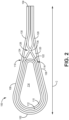
- FIG. 2 is a simplified cross-sectional view of airfoil 100 with a cross brace formed in the trailing edge void.
- FIG. 3 is a simplified close-up cross-sectional view of the trailing edge void and cross brace.
- FIG. 4 is a simplified perspective view of the cross-brace during formation.
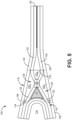
- FIG. 5 is a simplified close-up cross-sectional view of the cross brace and additional reinforcing elements. Steps 12-24 of method 10 are described below in combination together with FIGS. 2-5 .
- airfoil 100 includes leading edge 102 and oppositely disposed trailing edge 104.
- Each of pressure side 106 and oppositely disposed suction side 108 extends from leading edge 102 to trailing edge 104.
- Leading edge 102 and trailing edge 104 define a chord length, represented by line C, extending therebetween.
- a spanwise dimension (i.e., span) of airfoil 100 extends perpendicularly to line C (i.e., into/out of the page).
- Airfoil 100 can be formed from fabrics (i.e., as plies, sheets, braids, etc.) of woven ceramic tows in an exemplary embodiment. Such fabrics can include perpendicular warp and weft tows arranged in various two-dimensional woven architectures such as plain, harness (e.g., 3, 5, 8, etc.), twill, and non-symmetric. Other woven architectures can include three-dimensional architectures such as braids (e.g., biaxial or triaxial) and interlock (e.g., orthogonal, layer-to-layer, angle, etc.) architectures.
- the ceramic material can be silicon carbide or another suitable ceramic material.
- Airfoil 100 can be, for example, part of a stationary vane or rotor blade in a gas turbine engine.
- core plies 110 and 112 can be laid up on a mandrel (not shown) in a concentric manner such that ply 110 is concentrically inward of core ply 112.
- plies 110 and 112 define hollow core cavity 114.
- core cavity 114 is located proximate leading edge 102.
- Core cavity114 can be coextensive with the full span of airfoil 100.
- more than two plies can be used to form core cavity 114 depending, for example, on the type of airfoil and/or desired thickness of the walls surrounding core cavity 114.
- first (i.e., inner) overwrap 116 is placed around core plies 110 and 112. Overwrap 116 partially defines trailing edge 104 and trailing edge void 120 between core cavity 114 and trailing edge 104. In some embodiments, trailing edge void 120 can be coextensive with the full span of airfoil 100. First overwrap 116 extends around core plies 110 and 112 at leading edge 102, pressure side 106, and suction side 108.
- cross brace 126 can apply to either structure as described in the first and second examples below. Because cross brace 126 is formed from overwrap 116, it can be coextensive with trailing edge void 120 and the full span of airfoil 100. Aft of cross brace 126, free pressure side portion 122 and free suction side portion 124 are brought together to partially form trailing edge 104. Second overwrap 118 is then placed around first overwrap 116 and core plies 110 and 112.
- second overwrap 118 is the outermost fabric layer of the preform stage of airfoil 100. Free pressure side portion/end 128 and free suction side portion/end 130 of second overwrap 118 can be consolidated with portions 122 and 124 of first overwrap to form trailing edge 104. With cross brace 126 formed trailing edge void 120 is divided into four sub-cavities 120 A , 120 B , 120c, and 120 D (labeled in FIGS. 3 and 5 ), each coextensive with the full span of airfoil 100. Cross brace 126 has a generally "X" shaped cross-sectional geometry.
- cross brace 126 can be formed by weaving together free pressure side portion 122 and free suction side portion 124 of first overwrap 116.
- first overwrap 116 can be woven (two or three-dimensionally) over core plies 110 and 112, beginning, for example, at leading edge 102.
- tows 132 of free portion 122 can be woven through tows 134 of free portion 124. This creates intersecting point 136 (represented in FIG.
- cross brace 126 can involve a three-dimensional weaving technique to position one or more z-tows through free portions 122 and 124.
- cross brace 126 can be formed using localized stitching to join free portions 122 and 124 of first overwrap 116.
- first overwrap 116 can be woven over core plies 110 and 112 as in the previous example, or first overwrap 116 can be separately woven into a cloth and laid up over core plies 110 and 112.
- Aft of core cavity 114, free pressure side portion 122 and free suction side portion 124 can be joined (e.g., as two generally V-shaped segments pinched together, or as an H-shaped connection formed by Y-weaving) and stitched to form center point 136, returned to their respective pressure or suction sides 106, 108 to complete cross brace 126, and finally, brought together to partially form trailing edge 104.
- free portions 122 and 124 do not intersect and switch sides as in the previous example, rather, each remains disposed on their respective sides of airfoil 100 extending into trailing edge 104.
- Such an execution of cross brace 126 is represented in FIG. 5 .
- second overwrap 118 is placed around first overwrap 116 and core plies 110 and 112.
- Second overwrap 118 can be woven around overwrap 116 or can be separately woven and laid up around overwrap 116.
- second overwrap 118 is the outermost fabric layer of the preform stage of airfoil 100, but in alternative embodiment, one or more additional overwraps can be used.
- Free pressure side portion 128 and free suction side portion 130 of second overwrap 118 can be consolidated with portions 122 and 124 of first overwrap 116 to form trailing edge 104.
- Consolidation methods can include a simple stacking arrangement that is densified in step 22, as well as the joining of the individual layers/plies into one with Y-weaving.
- trailing edge void 120 can be divided into four sub-cavities 120 A , 120 B , 120c, and 120 D (labeled in FIGS. 3 and 4 , collectively referred to as "sub-cavities 120 A -120 D ").
- optional reinforcing elements can be added to trailing edge cavity 120.
- One such type of reinforcing element is reinforcing webbing 135, which can include targeted stitching with reinforcing z-tows, for example, between various combinations of free pressure side portions 122, 128 and free suction side portions 124, 130 of first and second overwraps 116 and 118, respectively.
- a second type of reinforcing element can include one or more fibrous inserts 138 placed in select sub-cavities 120 A -120 D . Inserts 138 can be shaped to complement sub-cavity geometry and can be coextensive with the sub-cavity and full span of airfoil 100. It should be mentioned that although optional reinforcing elements are shown in FIG. 5 with the non-intersecting cross brace 126 of the second example, reinforcing elements can be used with either type of cross brace disclosed herein.
- steps 18 and 20 may overlap, be reversed, and/or be repeated.
- webbing 135 can be added after second overwrap 118 is position, but prior to the consolidation of trailing edge 104.
- insert(s) 138 could be positioned after consolidation of trailing edge 104.
- the preform i.e., layered arrangement of plies and overwraps
- the preform can undergo matrix formation and densification using a chemical vapor infiltration (CVI) process.
- CVI chemical vapor infiltration
- the fibrous layers are infiltrated by reactant vapors, and a gaseous precursor deposits on the fibers.
- the matrix material can be a silicon carbide or other suitable ceramic material. Densification is carried out until the resulting CMC has reached the desired residual porosity. Typically, one or several interphases are deposited prior to the matrix to ensure that the composite fails in a non-brittle manner.
- Cross brace 126 has a reduced thickness and increased surface area compared to a conventional insert that would occupy the volume of trailing edge cavity 120, thus, the gaseous precursor can more evenly deposit on and within the various fiber structures within trailing edge cavity 120.
- the length of time required for satisfactory infiltration can, accordingly, be reduced.
- densification can additionally and/or alternatively include other methodologies such as, chemical vapor deposition (CVD), melt infiltration, and polymer infiltration and pyrolysis (PIP).
- CVD chemical vapor deposition
- melt infiltration melt infiltration
- PIP polymer infiltration and pyrolysis
- various post-processing steps can be performed, such as the application of one or more protective coatings (e.g., environmental and/or thermal barrier coatings).
- a bond coat can also be applied to facilitate bonding between the CMC and a protective coating.
- Other protective coatings especially those suitable for use in a gas turbine engine environment, are contemplated herein.
- trailing edge cavity 120 In operation of airfoil 100, trailing edge cavity 120 (i.e., as any of sub-cavities 120 A -120 D ) can receive a cooling airflow in the spanwise direction. With a conventional insert occupying nearly the entire volume of trailing edge cavity 120, such a cooling airflow could not be received.
- cross brace 126 can allow for improved thermal properties of airfoil 100, including reducing the thermal gradient and the temperature of trailing edge 104. Additionally, because cross brace 126 works as a truss structure, stress distribution at the trailing edge is improved over conventional designs. Finally, cross brace 126 is integral to the lay-up arrangement, and therefore will not come all or partially de-bonded from the surrounding structure during operation of the airfoil.
- a CMC component formed with the disclosed stabilized ceramic fabric can be incorporated into aerospace, maritime, or industrial equipment, to name a few, non-limiting examples.
- a method of forming a ceramic matrix composite airfoil includes forming a fibrous ceramic preform by laying up a plurality of plies to form a hollow core cavity, overwrapping the plurality of plies of the core cavity with a first overwrap layer, weaving together a tows of first free portion and tows of a second free portion of the first overwrap layer to form a cross brace, overwrapping the plurality of plies of the core cavity and the first overwrap layer with a second overwrap layer, and consolidating the first free portion and the second free portion of the first overwrap layer and a third free portion and a fourth free portion of the second overwrap layer to form a trailing edge.
- the method of the preceding paragraph can optionally include, additionally and/or alternatively, any one or more of the following features, configurations and/or additional components:
- overwrapping the plurality of plies of the core cavity with the first overwrap layer can include weaving a fabric layer around the plurality of plies.
- forming the cross brace can include interweaving tows of the first free portion and tows of the second free portion.
- overwrapping the plurality of plies of the core cavity with the first overwrap layer can include laying up a sheet over the plurality of plies of the core cavity.
- forming the cross brace can include stitching together a first free portion and a second free portion of the cloth (or sheet).
- the cross brace can be disposed in a trailing edge void of the fibrous preform, and the cross brace can partially define a plurality of sub-cavities of the trailing edge void.
- forming the fibrous ceramic preform can further include stitching a reinforcing fiber through the first overwrap layer and the second overwrap layer in the trailing edge void.
- forming the fibrous ceramic preform can further include inserting a fibrous insert into one of the plurality of sub-cavities.
- Any of the above methods can further include densifying the fibrous preform using at least one of chemical vapor infiltration, chemical vapor deposition, polymer infiltration and pyrolysis, and melt infiltration.
- a ceramic matrix composite airfoil includes a leading edge, a trailing edge opposite the leading edge, a pressure side extending from the leading edge to the trailing edge, a suction side opposite the pressure side and extending from the leading edge to the trailing edge, a hollow core cavity adjacent the leading edge and between the pressure side and the suction side, a trailing edge void between the leading edge and the trailing edge, and between the pressure side and the suction side, and a cross brace formed in the trailing edge void.
- the cross brace can have an "X" shaped cross-sectional geometry.
- a first free portion and an opposing second free portion of a ceramic overlap layer can form the cross brace and can partially form the trailing edge.
- the cross brace can include a central intersecting point.
- the first free portion can be disposed on the pressure side, and aft of the intersecting point, can be disposed on the suction side.
- the cross brace can partially define a plurality of sub-cavities of the trailing edge cavity.
- any of the above airfoils can further include a fibrous insert disposed within one of the plurality of sub-cavities.
- the cross brace can be coextensive with the trailing edge void and a span of the airfoil.
- the airfoil can be formed from tows of silicon carbide and a matrix of silicon carbide.
- the airfoil can be part of a stationary vane of a gas turbine engine.
- the cross brace cane be formed from a first woven ceramic overlap layer, and the first ceramic overlap layer can be disposed between ceramic plies defining the core cavity, and a second, outer ceramic overlap layer.
Landscapes
- Engineering & Computer Science (AREA)
- Chemical & Material Sciences (AREA)
- Materials Engineering (AREA)
- Mechanical Engineering (AREA)
- General Engineering & Computer Science (AREA)
- Composite Materials (AREA)
- Architecture (AREA)
- Ceramic Engineering (AREA)
- Turbine Rotor Nozzle Sealing (AREA)
Abstract
Description
- The present invention relates to ceramic matrix composites, and more particularly to the reinforcement thereof.
- In the manufacture of ceramic matrix composite (CMC) components, space filling inserts (e.g., "noodles") can be used to build upon and prevent large voids in the body of the CMC. Gas turbine engine airfoils commonly include such voids at their trailing edges. Such inserts can be difficult to form to neatly fill such cavities, and can sometimes become de-bonded from the surrounding walls of the airfoil. Alternative reinforcing techniques are therefore desirable.
- A method of forming a ceramic matrix composite airfoil includes forming a fibrous ceramic preform by laying up a plurality of plies to form a hollow core cavity, overwrapping the plurality of plies of the core cavity with a first overwrap layer, weaving together a tows of first free portion and tows of a second free portion of the first overwrap layer to form a cross brace, overwrapping the plurality of plies of the core cavity and the first overwrap layer with a second overwrap layer, and consolidating the first free portion and the second free portion of the first overwrap layer and a third free portion and a fourth free portion of the second overwrap layer to form a trailing edge.
- A ceramic matrix composite airfoil includes a leading edge, a trailing edge opposite the leading edge, a pressure side extending from the leading edge to the trailing edge, a suction side opposite the pressure side and extending from the leading edge to the trailing edge, a hollow core cavity adjacent the leading edge and between the pressure side and the suction side, a trailing edge void between the leading edge and the trailing edge, and between the pressure side and the suction side, and a cross brace formed in the trailing edge void.
- Features of embodiments are set forth in the dependent claims.
-
-
FIG. 1 is a flowchart illustrating a method of forming a CMC airfoil. -
FIG. 2 is a cross-sectional view of a CMC airfoil with a cross brace in a trailing edge void. -
FIG. 3 is a close-up cross-sectional view of the trailing edge void and cross brace ofFIG. 2 . -
FIG. 4 is a close-up perspective view of the cross brace ofFIGS. 2 and3 , in isolation, during formation. -
FIG. 5 is a close-up cross-sectional view of the trailing edge void and cross brace with additional reinforcing elements. - While the above-identified figures set forth one or more embodiments of the present disclosure, other embodiments are also contemplated, as noted in the discussion. In all cases, this disclosure presents the invention by way of representation and not limitation. It should be understood that numerous other modifications and embodiments can be devised by those skilled in the art, which fall within the scope and spirit of the principles of the invention. The figures may not be drawn to scale, and applications and embodiments of the present invention may include features and components not specifically shown in the drawings.
- This disclosure presents a method of forming a CMC airfoil from a fibrous preform. A lay-up arrangement is provided which forms a void proximate the trailing edge. To stabilize the void, an inner overwrap is formed into a cross brace at the location of the void. The overwrap can be interwoven or stitched together at the site of the cross brace. Additional reinforcing elements can be included in the trailing edge cavity.
-
FIG. 1 is a flowchartillustrating method 10 of forming a CMC airfoil with a reinforced trailing edge void.FIG. 2 is a simplified cross-sectional view ofairfoil 100 with a cross brace formed in the trailing edge void.FIG. 3 is a simplified close-up cross-sectional view of the trailing edge void and cross brace.FIG. 4 is a simplified perspective view of the cross-brace during formation.FIG. 5 is a simplified close-up cross-sectional view of the cross brace and additional reinforcing elements. Steps 12-24 ofmethod 10 are described below in combination together withFIGS. 2-5 . - As shown in
FIG. 2 ,airfoil 100 includes leadingedge 102 and oppositely disposedtrailing edge 104. Each ofpressure side 106 and oppositely disposedsuction side 108 extends from leadingedge 102 to trailingedge 104.Leading edge 102 andtrailing edge 104 define a chord length, represented by line C, extending therebetween. A spanwise dimension (i.e., span) ofairfoil 100 extends perpendicularly to line C (i.e., into/out of the page). -
Airfoil 100 can be formed from fabrics (i.e., as plies, sheets, braids, etc.) of woven ceramic tows in an exemplary embodiment. Such fabrics can include perpendicular warp and weft tows arranged in various two-dimensional woven architectures such as plain, harness (e.g., 3, 5, 8, etc.), twill, and non-symmetric. Other woven architectures can include three-dimensional architectures such as braids (e.g., biaxial or triaxial) and interlock (e.g., orthogonal, layer-to-layer, angle, etc.) architectures. The ceramic material can be silicon carbide or another suitable ceramic material. Airfoil 100 can be, for example, part of a stationary vane or rotor blade in a gas turbine engine. - At
step 12,core plies ply 110 is concentrically inward ofcore ply 112. When the mandrel is no longer in place,plies hollow core cavity 114. In the embodiment shown,core cavity 114 is located proximate leadingedge 102. Core cavity114 can be coextensive with the full span ofairfoil 100. In an alternative embodiment, more than two plies can be used to formcore cavity 114 depending, for example, on the type of airfoil and/or desired thickness of the walls surroundingcore cavity 114. - At
step 14, first (i.e., inner)overwrap 116 is placed aroundcore plies Overwrap 116 partially definestrailing edge 104 and trailingedge void 120 betweencore cavity 114 andtrailing edge 104. In some embodiments,trailing edge void 120 can be coextensive with the full span ofairfoil 100.First overwrap 116 extends aroundcore plies edge 102,pressure side 106, andsuction side 108. - At
step 16, aft ofcore cavity 114, free pressure side portion/end 122 and free suction side portion/end 124 offirst overwrap 116 are brought together to formcross brace 126. As used herein, the term "cross brace" can apply to either structure as described in the first and second examples below. Becausecross brace 126 is formed fromoverwrap 116, it can be coextensive withtrailing edge void 120 and the full span ofairfoil 100. Aft ofcross brace 126, freepressure side portion 122 and freesuction side portion 124 are brought together to partially formtrailing edge 104.Second overwrap 118 is then placed aroundfirst overwrap 116 andcore plies second overwrap 118 is the outermost fabric layer of the preform stage ofairfoil 100. Free pressure side portion/end 128 and free suction side portion/end 130 ofsecond overwrap 118 can be consolidated withportions trailing edge 104. Withcross brace 126 formedtrailing edge void 120 is divided into foursub-cavities FIGS. 3 and5 ), each coextensive with the full span ofairfoil 100.Cross brace 126 has a generally "X" shaped cross-sectional geometry. - By way of a first example,
cross brace 126 can be formed by weaving together freepressure side portion 122 and freesuction side portion 124 offirst overwrap 116. Such an execution ofcross brace 126 is represented inFIGS. 3 and4 . In such a case,first overwrap 116 can be woven (two or three-dimensionally) overcore plies edge 102. With enough offree portions core cavity 114,tows 132 offree portion 122 can be woven throughtows 134 offree portion 124. This creates intersecting point 136 (represented inFIG. 4 by a dashed line) aft/downstream of which the orientation offree portions pressure side portion 122 is disposed onsuction side 108 ofairfoil 100 as it transitions intotrailing edge 104, and similarly, freesuction side portion 124 is disposed onpressure side 106 ofairfoil 100. In some embodiments, the formation ofcross brace 126 can involve a three-dimensional weaving technique to position one or more z-tows throughfree portions - By way of a second example,
cross brace 126 can be formed using localized stitching to joinfree portions first overwrap 116. In such a case,first overwrap 116 can be woven over core plies 110 and 112 as in the previous example, orfirst overwrap 116 can be separately woven into a cloth and laid up over core plies 110 and 112. Aft ofcore cavity 114, freepressure side portion 122 and freesuction side portion 124 can be joined (e.g., as two generally V-shaped segments pinched together, or as an H-shaped connection formed by Y-weaving) and stitched to formcenter point 136, returned to their respective pressure orsuction sides cross brace 126, and finally, brought together to partially form trailingedge 104. As such,free portions airfoil 100 extending into trailingedge 104. Such an execution ofcross brace 126 is represented inFIG. 5 . - At
step 18,second overwrap 118 is placed aroundfirst overwrap 116 and core plies 110 and 112.Second overwrap 118 can be woven aroundoverwrap 116 or can be separately woven and laid up aroundoverwrap 116. In the embodiment shown,second overwrap 118 is the outermost fabric layer of the preform stage ofairfoil 100, but in alternative embodiment, one or more additional overwraps can be used. Freepressure side portion 128 and freesuction side portion 130 ofsecond overwrap 118 can be consolidated withportions first overwrap 116 to form trailingedge 104. Consolidation methods can include a simple stacking arrangement that is densified instep 22, as well as the joining of the individual layers/plies into one with Y-weaving. Withcross brace 126 formed andsecond overwrap 118 in place, trailingedge void 120 can be divided into foursub-cavities FIGS. 3 and4 , collectively referred to as "sub-cavities 120A-120D"). - At
step 20, optional reinforcing elements can be added to trailingedge cavity 120. One such type of reinforcing element is reinforcingwebbing 135, which can include targeted stitching with reinforcing z-tows, for example, between various combinations of freepressure side portions suction side portions second overwraps fibrous inserts 138 placed in select sub-cavities 120A-120D.Inserts 138 can be shaped to complement sub-cavity geometry and can be coextensive with the sub-cavity and full span ofairfoil 100. It should be mentioned that although optional reinforcing elements are shown inFIG. 5 with thenon-intersecting cross brace 126 of the second example, reinforcing elements can be used with either type of cross brace disclosed herein. - In some cases, all or portions of
steps second overwrap 118 is position, but prior to the consolidation of trailingedge 104. Conversely, insert(s) 138 could be positioned after consolidation of trailingedge 104. - At
step 22, the preform (i.e., layered arrangement of plies and overwraps) can undergo matrix formation and densification using a chemical vapor infiltration (CVI) process. During densification, the fibrous layers are infiltrated by reactant vapors, and a gaseous precursor deposits on the fibers. The matrix material can be a silicon carbide or other suitable ceramic material. Densification is carried out until the resulting CMC has reached the desired residual porosity. Typically, one or several interphases are deposited prior to the matrix to ensure that the composite fails in a non-brittle manner.Cross brace 126 has a reduced thickness and increased surface area compared to a conventional insert that would occupy the volume of trailingedge cavity 120, thus, the gaseous precursor can more evenly deposit on and within the various fiber structures within trailingedge cavity 120. The length of time required for satisfactory infiltration can, accordingly, be reduced. In an alternative embodiment, densification can additionally and/or alternatively include other methodologies such as, chemical vapor deposition (CVD), melt infiltration, and polymer infiltration and pyrolysis (PIP). - At
step 24, various post-processing steps can be performed, such as the application of one or more protective coatings (e.g., environmental and/or thermal barrier coatings). A bond coat can also be applied to facilitate bonding between the CMC and a protective coating. Other protective coatings, especially those suitable for use in a gas turbine engine environment, are contemplated herein. - In operation of
airfoil 100, trailing edge cavity 120 (i.e., as any of sub-cavities 120A-120D) can receive a cooling airflow in the spanwise direction. With a conventional insert occupying nearly the entire volume of trailingedge cavity 120, such a cooling airflow could not be received. Thus,cross brace 126 can allow for improved thermal properties ofairfoil 100, including reducing the thermal gradient and the temperature of trailingedge 104. Additionally, becausecross brace 126 works as a truss structure, stress distribution at the trailing edge is improved over conventional designs. Finally,cross brace 126 is integral to the lay-up arrangement, and therefore will not come all or partially de-bonded from the surrounding structure during operation of the airfoil. - A CMC component formed with the disclosed stabilized ceramic fabric can be incorporated into aerospace, maritime, or industrial equipment, to name a few, non-limiting examples.
- The following are non-exclusive descriptions of possible embodiments of the present invention.
- A method of forming a ceramic matrix composite airfoil includes forming a fibrous ceramic preform by laying up a plurality of plies to form a hollow core cavity, overwrapping the plurality of plies of the core cavity with a first overwrap layer, weaving together a tows of first free portion and tows of a second free portion of the first overwrap layer to form a cross brace, overwrapping the plurality of plies of the core cavity and the first overwrap layer with a second overwrap layer, and consolidating the first free portion and the second free portion of the first overwrap layer and a third free portion and a fourth free portion of the second overwrap layer to form a trailing edge.
- The method of the preceding paragraph can optionally include, additionally and/or alternatively, any one or more of the following features, configurations and/or additional components:
- In the above method, overwrapping the plurality of plies of the core cavity with the first overwrap layer can include weaving a fabric layer around the plurality of plies.
- In any of the above methods, forming the cross brace can include interweaving tows of the first free portion and tows of the second free portion.
- In any of the above methods, overwrapping the plurality of plies of the core cavity with the first overwrap layer can include laying up a sheet over the plurality of plies of the core cavity.
- In any of the above methods, forming the cross brace can include stitching together a first free portion and a second free portion of the cloth (or sheet).
- In any of the above methods, the cross brace can be disposed in a trailing edge void of the fibrous preform, and the cross brace can partially define a plurality of sub-cavities of the trailing edge void.
- In any of the above methods, forming the fibrous ceramic preform can further include stitching a reinforcing fiber through the first overwrap layer and the second overwrap layer in the trailing edge void.
- In any of the above methods, forming the fibrous ceramic preform can further include inserting a fibrous insert into one of the plurality of sub-cavities.
- Any of the above methods can further include densifying the fibrous preform using at least one of chemical vapor infiltration, chemical vapor deposition, polymer infiltration and pyrolysis, and melt infiltration.
- A ceramic matrix composite airfoil includes a leading edge, a trailing edge opposite the leading edge, a pressure side extending from the leading edge to the trailing edge, a suction side opposite the pressure side and extending from the leading edge to the trailing edge, a hollow core cavity adjacent the leading edge and between the pressure side and the suction side, a trailing edge void between the leading edge and the trailing edge, and between the pressure side and the suction side, and a cross brace formed in the trailing edge void.
- The airfoil of the preceding paragraph can optionally include, additionally and/or alternatively, any one or more of the following features, configurations and/or additional components:
In the above airfoil, the cross brace can have an "X" shaped cross-sectional geometry. - In any of the above airfoils, a first free portion and an opposing second free portion of a ceramic overlap layer can form the cross brace and can partially form the trailing edge.
- In any of the above airfoils, the cross brace can include a central intersecting point.
- In any of the above airfoils, the first free portion can be disposed on the pressure side, and aft of the intersecting point, can be disposed on the suction side.
- In any of the above airfoils, the cross brace can partially define a plurality of sub-cavities of the trailing edge cavity.
- Any of the above airfoils can further include a fibrous insert disposed within one of the plurality of sub-cavities.
- In any of the above airfoils, the cross brace can be coextensive with the trailing edge void and a span of the airfoil.
- In any of the above airfoils, the airfoil can be formed from tows of silicon carbide and a matrix of silicon carbide.
- In any of the above airfoils, the airfoil can be part of a stationary vane of a gas turbine engine.
- In any of the above airfoils, the cross brace cane be formed from a first woven ceramic overlap layer, and the first ceramic overlap layer can be disposed between ceramic plies defining the core cavity, and a second, outer ceramic overlap layer.
- While the invention has been described with reference to an exemplary embodiment(s), it will be understood by those skilled in the art that various changes may be made and equivalents may be substituted for elements thereof without departing from the scope of the invention. In addition, many modifications may be made to adapt a particular situation or material to the teachings of the invention without departing from the essential scope thereof. Therefore, it is intended that the invention not be limited to the particular embodiment(s) disclosed, but that the invention will include all embodiments falling within the scope of the appended claims.
Claims (15)
- A method of forming a ceramic matrix composite airfoil (100), the method comprising:
forming a fibrous ceramic preform by:laying up a plurality of plies (110, 112) to form a hollow core cavity (114);overwrapping the plurality of plies (110, 112) of the core cavity (114) with a first overwrap layer (116);weaving together tows (132) of a first free portion (122) and tows (134) of a second free portion (124) of the first overwrap layer (116) to form a cross brace (126);overwrapping the plurality of plies (110, 112) of the core cavity (114) and the first overwrap layer (116) with a second overwrap layer (118); andconsolidating the first free portion (112) and the second free portion (124) of the first overwrap layer (116) and a third free portion (128) and a fourth free portion (130) of the second overwrap layer (118) to form a trailing edge (104). - The method of claim 1, wherein overwrapping the plurality of plies (110, 112) of the core cavity (114) with the first overwrap layer (116) comprises: weaving a fabric layer around the plurality of plies (110, 112).
- The method of claim 1 or 2, wherein forming the cross brace (126) comprises interweaving the tows (132) of the first free portion (124) and the tows (134) of the second free portion (124).
- The method of any preceding claim, wherein overwrapping the plurality of plies (110, 112) of the core cavity (114) with the first overwrap layer (116) comprises laying up a sheet over the plurality of plies (110, 112) of the core cavity (114), wherein forming the cross brace (126) optionally comprises stitching together a first free portion and a second free portion of the sheet.
- The method of any preceding claim, wherein the cross brace (126) is disposed in a trailing edge void (120) of the fibrous preform, and wherein the cross brace (126) partially defines a plurality of sub-cavities (120A; 120B; 120c; 120D) of the trailing edge void (120), wherein forming the fibrous ceramic preform optionally further comprises stitching a reinforcing fiber through the first overwrap layer (116) and the second overwrap layer (118) in the trailing edge void (120).
- The method of claim 5, wherein forming the fibrous ceramic preform further comprises: inserting a fibrous insert (138) into one of the plurality of sub-cavities (120A; 120B; 120c; 120D).
- The method of any preceding claim and further comprising: densifying the fibrous preform using at least one of chemical vapor infiltration, chemical vapor deposition, polymer infiltration and pyrolysis, and melt infiltration.
- A ceramic matrix composite airfoil (100) comprising:a leading edge (102);a trailing edge (104) opposite the leading edge (102);a pressure side (106) extending from the leading edge (102) to the trailing edge (104);a suction side (108) opposite the pressure side (106) and extending from the leading edge (102) to the trailing edge (104);a hollow core cavity (114) adjacent the leading edge (102) and between the pressure side (106) and the suction side (108);a trailing edge void (120) between the leading edge (102) and the trailing edge (104), and between the pressure side (106) and the suction side (108); anda cross brace (126) formed in the trailing edge void (120).
- The airfoil of claim 8, wherein the cross brace (126) has an "X" shaped cross-sectional geometry.
- The airfoil of claim 8 or 9, wherein a first free portion (122) and an opposing second free portion (124) of a ceramic overlap layer (116) forms the cross brace (126) and partially forms the trailing edge (104).
- The airfoil of claim 10, wherein the cross brace (116) comprises a central intersecting point (136), wherein, optionally the first free portion (122) is disposed on the pressure side (106) forward of the central intersecting point (136), and aft of the central intersecting point (136), is disposed on the suction side (108).
- The airfoil of any of claims 8 to 11, wherein the cross brace (126) partially defines a plurality of sub-cavities (120A; 120B; 120c; 120D) of the trailing edge void (120), wherein the airfoil optionally further comprises a fibrous insert (138) disposed within one of the plurality of sub-cavities (120A; 120B; 120c; 120D).
- The airfoil of any of claims 8 to 12, wherein the cross brace (126) is coextensive with the trailing edge void (120) and a span of the airfoil (100).
- The airfoil of any of claims 8 to 13, wherein the airfoil (100) is formed from tows (110, 112) of silicon carbide and a matrix of silicon carbide; and/or
wherein the airfoil (100) is part of a stationary vane of a gas turbine engine. - The airfoil of any of claims 8 to 14, wherein the cross brace (126) is formed from a first woven ceramic overlap layer (116), and wherein the first ceramic overlap layer (116) is disposed between ceramic plies (110, 112) defining the core cavity (114), and a second, outer ceramic overlap layer (118).
Applications Claiming Priority (1)
| Application Number | Priority Date | Filing Date | Title |
|---|---|---|---|
| US202263326387P | 2022-04-01 | 2022-04-01 |
Publications (1)
| Publication Number | Publication Date |
|---|---|
| EP4253725A1 true EP4253725A1 (en) | 2023-10-04 |
Family
ID=85778727
Family Applications (1)
| Application Number | Title | Priority Date | Filing Date |
|---|---|---|---|
| EP23164847.8A Pending EP4253725A1 (en) | 2022-04-01 | 2023-03-28 | Cmc trailing edge 3d weaved cross brace |
Country Status (2)
| Country | Link |
|---|---|
| US (1) | US11905851B2 (en) |
| EP (1) | EP4253725A1 (en) |
Families Citing this family (3)
| Publication number | Priority date | Publication date | Assignee | Title |
|---|---|---|---|---|
| FR3120249B1 (en) * | 2021-03-01 | 2023-12-29 | Safran Aircraft Engines | Blade comprising a composite material structure and associated manufacturing method |
| US12601267B2 (en) * | 2024-02-15 | 2026-04-14 | Rtx Corporation | Forming gas turbine engine airfoils from CMCs with a kickback to facilitate mandrel removal |
| US12529320B1 (en) | 2024-09-10 | 2026-01-20 | Rtx Corporation | Partial shear tube y-weave trailing edge for a CMC vane and method therefor |
Citations (3)
| Publication number | Priority date | Publication date | Assignee | Title |
|---|---|---|---|---|
| US7600979B2 (en) * | 2006-11-28 | 2009-10-13 | General Electric Company | CMC articles having small complex features |
| US20190145269A1 (en) * | 2016-05-10 | 2019-05-16 | Siemens Aktiengesellschaft | Ceramic component for combustion turbine engines |
| EP4180633A1 (en) * | 2021-11-12 | 2023-05-17 | Raytheon Technologies Corporation | Airfoil of a gas turbine with fiber plies having interdigitated fingers in trailing end |
Family Cites Families (3)
| Publication number | Priority date | Publication date | Assignee | Title |
|---|---|---|---|---|
| GB0424481D0 (en) | 2004-11-05 | 2004-12-08 | Rolls Royce Plc | Composite aerofoil |
| GB2573137B (en) * | 2018-04-25 | 2020-09-23 | Rolls Royce Plc | CMC aerofoil |
| WO2020209847A1 (en) | 2019-04-10 | 2020-10-15 | Siemens Aktiengesellschaft | Three dimensional ceramic matrix composite wall structures fabricated by using pin weaving techniques |
-
2023
- 2023-03-27 US US18/126,556 patent/US11905851B2/en active Active
- 2023-03-28 EP EP23164847.8A patent/EP4253725A1/en active Pending
Patent Citations (3)
| Publication number | Priority date | Publication date | Assignee | Title |
|---|---|---|---|---|
| US7600979B2 (en) * | 2006-11-28 | 2009-10-13 | General Electric Company | CMC articles having small complex features |
| US20190145269A1 (en) * | 2016-05-10 | 2019-05-16 | Siemens Aktiengesellschaft | Ceramic component for combustion turbine engines |
| EP4180633A1 (en) * | 2021-11-12 | 2023-05-17 | Raytheon Technologies Corporation | Airfoil of a gas turbine with fiber plies having interdigitated fingers in trailing end |
Also Published As
| Publication number | Publication date |
|---|---|
| US20230313692A1 (en) | 2023-10-05 |
| US11905851B2 (en) | 2024-02-20 |
Similar Documents
| Publication | Publication Date | Title |
|---|---|---|
| EP4253725A1 (en) | Cmc trailing edge 3d weaved cross brace | |
| JP5599865B2 (en) | Method for manufacturing turbomachine blades made from composite materials | |
| EP1768893B1 (en) | Ceramic matrix composite airfoil trailing edge arrangement | |
| US8846147B2 (en) | Method for manufacturing a complexly shaped composite material part | |
| JP6254532B2 (en) | Fiber reinforced structure for composite parts with thin wall | |
| CN108699916A (en) | Ceramic matrix composite turbine machine component with classification fiber reinforced ceramic-base bottom | |
| CN102099313B (en) | Method for the manufacture of nozzle or diverging nozzle elements made of composite material | |
| US20130017094A1 (en) | Method of fabricating a composite material blade having internal channels, and a composite material turbine engine blade | |
| JP6426722B2 (en) | Textile structure with aggregation of floats | |
| CN108367524B (en) | Method of manufacturing a composite part having a body integral with one or more platforms | |
| US9539787B2 (en) | Multilayer woven fibrous structure including a hollow tubular part, production method thereof and composite part comprising same | |
| US9550340B2 (en) | Composite material part comprising fixing means | |
| JP2014518976A (en) | Turbomachine rotor with composite legged blades | |
| US20190145269A1 (en) | Ceramic component for combustion turbine engines | |
| JP6366609B2 (en) | Method of manufacturing a curved honeycomb structure made of composite material | |
| CN102648080A (en) | Woven preform, composite, and method of making thereof | |
| WO2014143339A1 (en) | Gas turbine engine airflow member, corresponding turbomachine component and manufacturing method | |
| JP6959223B2 (en) | Composite material parts | |
| EP4177052B1 (en) | 3d woven space filler | |
| EP4571048A1 (en) | Method to tie composite vane platform and airfoil design details | |
| Grosch et al. | Using 3D weaving for additive manufacturing of ceramic preforms | |
| US20260009332A1 (en) | One-piece blade preform incorporating overlapping unidirectional fabric portions | |
| US20260008727A1 (en) | Fibrous blank with at least one disconnection having an alternation of weaving |
Legal Events
| Date | Code | Title | Description |
|---|---|---|---|
| PUAI | Public reference made under article 153(3) epc to a published international application that has entered the european phase |
Free format text: ORIGINAL CODE: 0009012 |
|
| STAA | Information on the status of an ep patent application or granted ep patent |
Free format text: STATUS: THE APPLICATION HAS BEEN PUBLISHED |
|
| AK | Designated contracting states |
Kind code of ref document: A1 Designated state(s): AL AT BE BG CH CY CZ DE DK EE ES FI FR GB GR HR HU IE IS IT LI LT LU LV MC ME MK MT NL NO PL PT RO RS SE SI SK SM TR |
|
| RAP3 | Party data changed (applicant data changed or rights of an application transferred) |
Owner name: RTX CORPORATION |
|
| STAA | Information on the status of an ep patent application or granted ep patent |
Free format text: STATUS: REQUEST FOR EXAMINATION WAS MADE |
|
| 17P | Request for examination filed |
Effective date: 20240320 |
|
| RBV | Designated contracting states (corrected) |
Designated state(s): AL AT BE BG CH CY CZ DE DK EE ES FI FR GB GR HR HU IE IS IT LI LT LU LV MC ME MK MT NL NO PL PT RO RS SE SI SK SM TR |
|
| STAA | Information on the status of an ep patent application or granted ep patent |
Free format text: STATUS: EXAMINATION IS IN PROGRESS |
|
| 17Q | First examination report despatched |
Effective date: 20250604 |