EP4253654A1 - Concrete slab joint forming system - Google Patents
Concrete slab joint forming system Download PDFInfo
- Publication number
- EP4253654A1 EP4253654A1 EP23151217.9A EP23151217A EP4253654A1 EP 4253654 A1 EP4253654 A1 EP 4253654A1 EP 23151217 A EP23151217 A EP 23151217A EP 4253654 A1 EP4253654 A1 EP 4253654A1
- Authority
- EP
- European Patent Office
- Prior art keywords
- former
- concrete
- load transfer
- receipt
- tongue
- Prior art date
- Legal status (The legal status is an assumption and is not a legal conclusion. Google has not performed a legal analysis and makes no representation as to the accuracy of the status listed.)
- Pending
Links
Images
















Classifications
-
- E—FIXED CONSTRUCTIONS
- E01—CONSTRUCTION OF ROADS, RAILWAYS, OR BRIDGES
- E01C—CONSTRUCTION OF, OR SURFACES FOR, ROADS, SPORTS GROUNDS, OR THE LIKE; MACHINES OR AUXILIARY TOOLS FOR CONSTRUCTION OR REPAIR
- E01C11/00—Details of pavings
- E01C11/02—Arrangement or construction of joints; Methods of making joints; Packing for joints
- E01C11/04—Arrangement or construction of joints; Methods of making joints; Packing for joints for cement concrete paving
- E01C11/10—Packing of plastic or elastic materials, e.g. wood, resin
- E01C11/106—Joints with only prefabricated packing; Packings therefor
-
- E—FIXED CONSTRUCTIONS
- E01—CONSTRUCTION OF ROADS, RAILWAYS, OR BRIDGES
- E01C—CONSTRUCTION OF, OR SURFACES FOR, ROADS, SPORTS GROUNDS, OR THE LIKE; MACHINES OR AUXILIARY TOOLS FOR CONSTRUCTION OR REPAIR
- E01C11/00—Details of pavings
- E01C11/02—Arrangement or construction of joints; Methods of making joints; Packing for joints
- E01C11/04—Arrangement or construction of joints; Methods of making joints; Packing for joints for cement concrete paving
- E01C11/14—Dowel assembly ; Design or construction of reinforcements in the area of joints
-
- E—FIXED CONSTRUCTIONS
- E04—BUILDING
- E04B—GENERAL BUILDING CONSTRUCTIONS; WALLS, e.g. PARTITIONS; ROOFS; FLOORS; CEILINGS; INSULATION OR OTHER PROTECTION OF BUILDINGS
- E04B1/00—Constructions in general; Structures which are not restricted either to walls, e.g. partitions, or floors or ceilings or roofs
- E04B1/38—Connections for building structures in general
- E04B1/48—Dowels, i.e. members adapted to penetrate the surfaces of two parts and to take the shear stresses
- E04B1/483—Shear dowels to be embedded in concrete
-
- E—FIXED CONSTRUCTIONS
- E04—BUILDING
- E04B—GENERAL BUILDING CONSTRUCTIONS; WALLS, e.g. PARTITIONS; ROOFS; FLOORS; CEILINGS; INSULATION OR OTHER PROTECTION OF BUILDINGS
- E04B1/00—Constructions in general; Structures which are not restricted either to walls, e.g. partitions, or floors or ceilings or roofs
- E04B1/62—Insulation or other protection; Elements or use of specified material therefor
- E04B1/66—Sealings
- E04B1/68—Sealings of joints, e.g. expansion joints
- E04B1/6807—Expansion elements for parts cast in situ
-
- E—FIXED CONSTRUCTIONS
- E01—CONSTRUCTION OF ROADS, RAILWAYS, OR BRIDGES
- E01C—CONSTRUCTION OF, OR SURFACES FOR, ROADS, SPORTS GROUNDS, OR THE LIKE; MACHINES OR AUXILIARY TOOLS FOR CONSTRUCTION OR REPAIR
- E01C2201/00—Paving elements
- E01C2201/16—Elements joined together
Definitions
- concrete floors and roadways include a series of separate individually poured or cast-in-place concrete slabs that are referred to herein as "concrete slabs.”
- concrete slabs Various known issues with such concrete slabs relate to the joint between adjacent concrete slabs, the relative movements of adjacent concrete slabs when loads are placed on the concrete slabs, and the opening that forms between adjacent concrete slabs at the joint.
- Contraction joints Two types of joints are often used for concrete slabs. Construction joints are often used between separately individually poured adjacent concrete slabs (that are poured at sequential times). Contraction joints (which are sometimes called control joints) are often used for simultaneously poured adjacent concrete slabs. Contraction joints are often partially formed by vertically cutting a larger concrete slab at a desired location of the contraction joint to form the separate adjacent concrete slabs. The vertical cut often extends approximately one third of the way through the depth of the concrete. When the larger concrete slab cracks along the cut, the respective concrete slabs are able to separate. Contraction joints are thus often used to control natural cracking in concrete slabs from stresses caused by concrete shrinkage, thermal contraction, moisture or thermal gradients within the concrete, and/or various external forces on the concrete slabs.
- adjacent concrete slabs are also subject to loads that can cause the movements of the concrete slabs relative to one another.
- Various construction and contraction joints include load transferring dowels of various different geometries that connect adjacent concrete slabs such that the movement of one concrete slab causes the movement of the adjacent concrete slab. In other words, these load transferring dowels connect the adjacent concrete slabs such that they substantially move together when a load is placed on one of the adjacent concrete slabs.
- Various embodiments of the present disclosure provide concrete slab joint forming systems and methods of using such concrete slab joint forming systems for forming joints between adjacent concrete slabs.
- the concrete slab joint forming system includes: (1) a concrete slab joint former, (2) an extension connector, (3) a cross intersection connector, (4) a tee intersection connector, (5) an end connector, (6) a field cut connector, and/or (7) any combination of any quantity of these components (1) to (6).
- Each of the extension connector, the cross intersection connector, the tee intersection connector, and the field cut connector are connectable to one or more concrete slab joint formers or extension connectors.
- the end connector is connectable to one concrete slab joint former or to one extension connector.
- each of the extension connector, the cross intersection connector, the tee intersection connector, the end connector, and the field cut connector are selectively usable with one or more of the concrete slab joint formers and one or more extension connectors to form one or more joints for concrete slabs and the respective concrete slabs themselves.
- the concrete slab joint forming system of various embodiments of the present disclosure reduce: (1) the quantity of components for forming concrete slab, (2) the weight of the components for forming concrete slabs, (3) the complexity of the assembly and installation of the components for forming concrete slabs, and/or (4) the assembly and installation time for the components needed for forming concrete slabs, as compared to various known concrete slab forming and load transfer apparatus.
- mounting methods such as mounted, attached, connected, and the like, are not intended to be limited to direct mounting methods but should be interpreted broadly to include indirect and operably mounted, attached, connected and like mounting methods. This specification is intended to be taken as a whole and interpreted in accordance with the principles of the present disclosure and as understood by one of ordinary skill in the art.
- Various embodiments of the present disclosure provide concrete slab joint forming systems and methods of using such concrete slab joint forming systems for forming joints between adjacent concrete slabs and the concrete slabs themselves.
- the concrete slab joint forming system may sometimes be referred to herein as the joint forming system or the system. Such abbreviations are not meant to limit the scope of the present disclosure.
- the concrete slab joint forming systems and methods are dowel-less, and thus do not include any additional dowels that extend into the adjacent concrete slabs.
- the lips and tongues of the adjacent concrete slabs perform the functions previously performed by such additional dowels.
- FIG. 1 to 56 One example embodiment of the concrete slab joint forming system of the present disclosure is shown in Figures 1 to 56 .
- This example embodiment of the concrete slab joint forming system includes a concrete slab joint former 100 shown in Figures 1 to 8 , and various different connectors shown in Figures 9 to 48 .
- the various different connectors in this example embodiment include: (a) an extension connector 200 shown in Figures 9 to 16 , (b) a cross intersection connector 300 shown in Figures 17 to 24 , (c) a tee intersection connector 400 shown in Figures 25 to 32 , (d) an end connector 500 shown in Figures 33 to 40 , and (e) a field cut connector 600 shown in Figures 41 to 48 .
- the concrete slab joint former 100 can be employed with or without any of the connectors 200, 300, 400, 500, and/or 600. Multiple concrete slab joint formers 100 can be employed with each other and with or without one or more of any of the connectors 200, 300, 400, 500, and/or 600 to form joints for concrete slabs and the concrete slabs themselves.
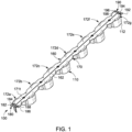
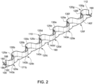
- this concrete slab joint former 100 includes: (a) an elongated load transfer tongue former 110; and (b) an elongated load transfer lip former 160 connected to the top of the load transfer tongue former 110.
- the load transfer tongue former 110 and the load transfer lip former 160 are configured to form opposing load transfer lips 1100 and 2100 respectively of the adjacent slabs 1000 and 2000 and opposing load transfer tongues 1200a, 1200b, 1200c, 1200d, and 1200e and 2200a, 2200b, 2200c, 2200d, 2200e, and 2200f respectively of the adjacent concrete slabs 1000 and 2000 such as shown in Figures 53 , 54, 55, and 56 , and as further discussed below.
- the lips rest of the respective concrete slabs rest on the respective opposing tongues of the concrete slabs.
- Such opposing load transfer lips and opposing load transfer tongues are configured to transfer forces (such as but not limited to vertical forces) between the adjacent concrete slabs without the use of additional dowels as further explained below.
- the concrete slab joint former 100 may additionally itself function as a dowel for assisting in the transfer of such forces between adjacent concrete slabs.
- the concrete slab joint former 100 may sometimes be referred to herein as the joint former 100 for brevity.
- the concrete slab joint former 100 is molded from a polymer. It should be appreciated that the concrete slab joint former 100 can be made from other suitable materials in accordance with the present disclosure. In this illustrated example embodiment, this concrete slab joint former 100 is a single monolithically formed piece that includes the elongated load transfer tongue former 110 and the elongated load transfer lip former 160. In other embodiments, the elongated load transfer tongue former 110 and the elongated load transfer lip former 160 or parts thereof can be separately formed and connected together.
- the load transfer tongue former 110 includes an upright vertically extending waveform 112 having multiple tongue forming concrete receipt sections 120a, 120b, 120c, 120d, 120e, 120f, and 120g.
- the waveform 112 has a longitudinally extending central axis (not shown).
- Each of the sections 120a, 120b, 120c, 120d, 120e, 120f, and 120g is connected to a respective adjacent section by a section connector.
- section 120a is connected to section 120b by section connector 125a
- section 120b is connected to section 120c by section connector 125b
- section 120c is connected to section 120d by section connector 125c
- section 120d is connected to section 120e by section connector 125e
- section 120e is connected to section 120f by section connector 125e
- section 120f is connected to section 120g by section connector 125f.
- Each of the section connectors 125a, 125b, 125c, 125d, 125e, and 125f defines an upright vertically extending substrate fastener receiver (not labeled) that is shaped, sized, and otherwise configured to receive a fastener (such as a nail as shown in Figure 49 ) that connects the concrete slab joint former 100 to a substrate (not shown) on which the concrete slabs formed using the joint former 100 will be positioned.
- a fastener such as a nail as shown in Figure 49
- the sections 120b, 120c, 120d, 120e, and 120f respectively include first tongue forming concrete receipt segments 130b, 130c, 130d, 130e, and 130f that each extends outwardly in a first direction from the central axis and respectively include second tongue forming concrete receipt segments 140b, 140c, 140d, 140e, and 140f that each extends outwardly in a second opposite direction from the central axis.
- the adjacent segments of each of the sections 120b, 120c, 120d, 120e, and 120f thus extend in opposing directions (e.g., the first segment of each of the sections extend in the first direction and second segment of each of the concrete receipt sections extend in the second direction).
- the section 120a has a tongue forming concrete receipt segment 140a that extends outwardly in the second direction from the central axis.
- the section 120g has a tongue forming concrete receipt segment 130g that extends outwardly in the first opposite direction from the central axis.
- the plurality of tongue forming concrete receipt segments 130b, 130c, 130d, 130e, 130f, and 130f respectively form a plurality of spaced-apart first slab concrete receipt pockets 138b, 138c, 138d, 138e, 138f, and 138g
- Each of the plurality of first slab concrete receipt pockets 138b, 138c, 138d, 138e, 138f, and 138g are wider at their openings, narrower at their innermost points, and are inwardly tapered from their openings to their innermost points.
- the plurality of the tongue forming concrete receipt segments 140a, 140b, 140c, 140d, 140e, and 140f respectively form a plurality of spaced-apart second slab concrete receipt pockets 148a, 148b, 148c, 148d, 148e, and 148f.
- Each of the second slab concrete receipt pockets 148a, 148b, 148c, 148d, 148e, and 148f are wider at their openings, narrower at their innermost points, and are inwardly tapered from their openings to their innermost points.
- the plurality of spaced apart first slab concrete receipt pockets 138b, 138c, 138d, 138e, 138f, and 138g alternate with the plurality of spaced apart second slab concrete receipt pockets 148a, 148b, 148c, 148d, 148e, and 148f in the directions of their respective openings, and are inwardly tapered from their openings to their innermost points.
- the sections 120a, 120b, 120c, 120d, 120e, 120f, and 120g each are of the same height in this example embodiment. It should be appreciated that the height of the sections can vary in accordance with the present disclosure. In various different example embodiments, the height of the waveform 112 is 2.75 inches (6.985 cms), 3.75 inches (9.525 cms), 5.5 inches (13.97 cms), or 7.5 inches (19.05 cms). These example heights, can for example be used with concrete slabs have heights (generally referred to as thicknesses) of between 5 inches (12.7 cms) and 16 inches (40.64 cms). The heights will thus generally depend on the heights of the concrete slabs in various embodiments.
- All of the segments of the sections 120a, 120b, 120c, 120d, 120e, 120f, and 120g define the same respective pocket depths in this example embodiment. It should be appreciated that the depths of two or more of the pockets defined by the segments can vary in accordance with the present disclosure. In this various example embodiments, the pocket depth of the waveform 112 is 5 inches (12.7 cms), however the depth can depend on the desired depth of the lips and tongues of the concrete slabs.
- All of the segments of the sections 120a, 120b, 120c, 120d, 120e, 120f, and 120g have the same radius of curvature in this example embodiment. It should also be appreciated that the radius of curvatures of two or more of the segments of the sections can vary in accordance with the present disclosure.
- the curvatures can be considered to at least partially define the amplitude of the waveform 112. It should be appreciated that the amplitude of the waveform can vary in accordance with the present disclosure. It should also be appreciated that a single waveform can have a varying amplitude in accordance with the present disclosure.
- the quantity of sections of the waveform 112 and thus the quantity of segments of the waveform 112 can vary in accordance with the present disclosure, such as based on the length of the concrete slab joint former 100.
- the waveform 112 is 69 inches (175.26 cms). It should thus be appreciated that the waveform 112 can be made in other suitable sizes, shapes, and configurations in accordance with the present disclosure.
- the load transfer lip former 160 includes an elongated central section 170, a first end connection section 180, and a second end connection section 190, each of which are connected to the top of the waveform 112 in this example embodiment. In other embodiments, only the elongated central section 170 is connected to the top of the waveform 112 and the first end connection section 180 and the second end connection section 190 are connected to opposite ends of the waveform 112 and extend in opposing directions from the waveform 112.
- the central section 170 is connected to the top of the waveform 112 and extends substantially the entire length of the waveform 112.
- the central section 170 includes horizontally extending top and bottom surfaces 171t and 171b that are flat (or substantially flat), extend in parallel (or substantially horizontal parallel) planes to one another, and have a constant thickness or height in this illustrated example embodiment.
- the central section 170 includes a plurality of sections 172a, 172b, 172c, 172d, 172e, 172f, and 172g that correspond with the sections 120a, 120b, 120c, 120d, 120e, 120f, and 120g of the waveform 112.
- the plurality of sections 172b, 172c, 172d, 172e, 172f, and 172g respectively have a plurality of segments 173b, 173c, 173d, 173e, 173f, and 173g that correspond to segments 130b, 130c, 130d, 130e, 130f, and 130g of the waveform 112.
- the plurality of sections 172b, 172c, 172d, 172e, 172f, and 172g also respectively have a plurality of segments 174a, 174b, 174c, 174d, 174e, and 174f, that correspond with the segments 140a, 140b, 140c, 140d, 140e, and 140f of the waveform 112.
- each of the segments 173b, 173c, 173d, 173e, 173f, 173g, 174a, 174b, 174c, 174d, 174e, and 174f define a plurality of spaced-apart air and/or moisture release openings (not labeled) that each extend from the bottom surface 171b of the central section 170 to the top surface 171t of the central section 170.
- the segments also respectively define a plurality of spaced-apart edge member attachment openings (not individually labeled) that each extend from the bottom surface 171b of the central section 170 to the top surface 171t of the central section 170 that enable the bottom upright wall of an edge member assembly to be attached (by suitable fasteners (not shown)) above and to the load transfer lip former 160 and thus the concrete slab joint former 100.
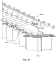
- Figure 57 shows an example of a bottom upright wall 5100 of an edge member assembly 5000 attached (by suitable fasteners (not shown)) above and to a load transfer lip former 160 and thus the concrete slab joint former 100.
- the concrete slab joint former 100 of the present disclosure can additionally function with a joint edge assembly to form a construction joint between two adjacent slabs.
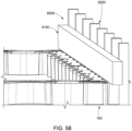
- the segments also respectively define a plurality of spaced-apart formwork receipt areas 178a, 178b, 178c, 178d, 178e, 178f, 178g, 178h, 178i, 178j, 178k, and 1781 configured to receive upright stakes of a formwork such as partially shown in Figure 58 ) for forming construction joints between adjacent concrete slabs.
- the concrete slab joint former 100 can be used with formwork for construction joints where one of the concrete slabs is poured and hardened before the adjacent concrete slab.
- a horizontally extending two-by-four 6100 is positioned over the lip former and attached to the stakes 6200.
- the indented spaced-apart formwork receipt areas 178a, 178b, 178c, 178d, 178e, 178f, 178g, 178h, 178i, 178j, 178k, and 1781 enable the stakes and the two-by-four to be positioned such the inside surface of the two-by-four is directly aligned with the longitudinal center axis of the load transfer lip former 160 and the waveform 112 for forming the outer side surface of the concrete slab.
- the first end connection section 180 includes top and bottom surfaces (not labeled).
- the first end connection section 180 includes a locking member portion 182 and a locking member receipt portion 186.
- the locking member portion 182 includes an upwardly extending locking member 184 (which is this example embodiment is an upwardly extending locking tab).
- the locking member receipt portion 186 defines a locking member receipt opening 188 configured to securely but releasably receive a locking member (and in this example embodiment an upwardly extending locking tab).
- the second end connection section 190 includes top and bottom surfaces (not labeled).
- the second end connection section 190 includes a locking member portion 192 and a locking member receipt portion 196.
- the locking member portion 192 includes an upwardly extending locking member 194 (which is this example embodiment is an upwardly extending locking tab).
- the locking member receipt portion 186 defines a locking member receipt opening 198 configured to securely but releasably receive a locking member (and in this example embodiment an upwardly extending locking tab).
- the first end connection section 180 and the second end connection section 190 are thus configured with the locking member portion 182 and the locking member receipt portion 186 oppositely positioned from the locking member portion 192 and the locking member receipt portion 196. This enables two the concrete slab joint former 100 to be connected to each other end to end such as shown in Figure 49 .
- the elongated lip former 160 further defines a longitudinally and upwardly extending central crack initiator 162 in the top surfaces of the central section 170, the first end connection section 180, and the second end connection section 190.
- This crack initiator 162 facilitates alignment of the joint former and an indication to the installer for alignment purposes as to where the cut in the concrete should be made to form the contraction joint between and to form the adjacent concrete slabs.
- This crack initiator 162 further facilitates the forming of the crack or separation in the concrete to form the separate adjacent concrete slabs. Specifically, when the concrete is cut from the top to form the location of the separation between the two concrete slabs and to form the contraction joint, the crack initiator can provide a weakened area in the concrete that will assist in forming the separation in the correct location.
- each concrete slab joint former 100 is positionable at an area where a contraction joint will be formed between adjacent concrete slabs, as further discussed below.
- the extension connector 200 of the concrete slab joint forming system is substantially similar to the concrete slab joint former 100 but is substantially shorter in length.
- the extension connector 200 includes: (a) a load transfer tongue former 210; and (b) a load transfer lip former 260 connected to the top of the load transfer tongue former 210.
- the load transfer tongue former 210 and the load transfer lip former 260 are configured to form opposing load transfer lips and opposing load transfer tongues in the adjacent concrete slabs as further discussed below and such that the opposing load transfer lips and opposing load transfer tongues are configured to transfer vertical forces between the adjacent concrete slabs without the use of dowels as further explained below.
- the extension connector 200 is molded from a polymer. It should be appreciated that the extension connector 200 can be made from other suitable materials in accordance with the present disclosure.
- this extension connector 200 is a single monolithically formed piece that includes the load transfer tongue former 210 and the load transfer lip former 260. In other embodiments, the load transfer tongue former 210 and the load transfer lip former 260 or parts thereof can be separately formed and connected together.
- the load transfer tongue former 210 includes an upright vertically extending waveform 212 having two tongue forming concrete receipt sections 220a and 220b.
- the waveform 212 has a longitudinally extending central axis (not shown).
- the sections 220a and 220b are connected by a section connector 225a.
- the section connector 225a defines an upright vertically extending substrate fastener receiver (not labeled) that is shaped, sized, and otherwise configured to receive a fastener (such as shown in Figure 49 ) that connects the extension connector 200 to a substrate (not shown) on which the concrete slabs partially formed by the extension connector 200 will be positioned.
- the section 220a has a tongue forming concrete receipt segment 230a that extends outwardly in a first direction from the central axis.
- the tongue forming concrete receipt segment 230a forms a slab concrete receipt pocket 238a that is wider at its opening, narrower at its innermost points, and is inwardly tapered from its opening to their innermost points.
- the section 220b has a tongue forming concrete receipt segment 240b that extends outwardly in a second opposite direction from the central axis.
- the tongue forming concrete receipt segment 240b forms a second slab concrete receipt pocket 248b that is wider at its opening, narrower at its innermost points, and is inwardly tapered from its openings to its innermost points.
- the opening of the first slab concrete receipt pocket 238a faces in an opposite direction as the opening of the second slab concrete receipt pocket 248b.
- the sections 220a and 220b each are of the same height in this example embodiment. It should be appreciated that the height of the sections can vary in accordance with the present disclosure. In various different example embodiments, the heights of the waveform 212 is 2.75 inches (6.985 cms), 3.75 inches (9.525 cms), 5.5 inches (13.97 cms), or 7.5 inches (19.05 cms).
- the segments of the sections 220a and 220b form pockets of the same depth in this example embodiment. It should be appreciated that the depths of the pockets formed by the segments can vary in accordance with the present disclosure. In this example embodiment, the depth of each pocket of the waveform 212 is 5 inches (12.7 cms), however the depth can depend on the desired depth of the lips and tongues of the concrete slabs.
- the segments of the sections 220a and 220b have the same radius of curvature in this example embodiment. It should also be appreciated that the radius of curvatures of the segments of the sections can vary in accordance with the present disclosure. The curvatures can be considered to define the amplitude of the waveform 212.
- the quantity of sections of the waveform 212 and thus the quantity of segments of the waveform 212 can vary in accordance with the present disclosure, such as based on the length of the extension connector 200.
- the waveform 212 is 12 inches (30.48 cms). It should also be appreciated that the waveform 212 can be made in other suitable sizes, shapes, and configurations in accordance with the present disclosure.
- the load transfer lip former 260 includes a central section 270, a first end connection section 280, and a second end connection section 290, each of which are connected to the top of the waveform 212.
- the central section 270 is attached to the top of the waveform 212 and extends substantially the entire length of the waveform 212.
- the central section 270 includes top and bottom surfaces (not labeled) that are flat (or substantially flat) and extend in parallel (or substantially parallel) planes to one another in this illustrated example embodiment.
- the central section 270 includes a two sections 272a and 272b that correspond with the sections 220a and 220b of the waveform 212.
- the sections 272a and 272b respectively have a plurality of segments 273a and 273b that correspond with the segments 240a and 240b of the waveform 212.
- each of the segments 240a and define a plurality of spaced-apart air release openings (not labeled) that each extend from the bottom surface 271b of the central section 270 to the top surface 271t of the central section 270.
- These air release opening enable air caught in the concrete under the load transfer lip former 260 to escape through such openings.
- the segments can define a plurality of spaced-apart edge member attachment openings that enable edge members to be attached above and to the load transfer lip former 260 and thus the extension connector 200.
- the segments can define a plurality of spaced-apart formwork receipt areas that can be used to receive upright formwork members.
- the first end connection section 280 includes top and bottom surfaces (not labeled).
- the first end connection section 280 includes a locking member portion 282 and a locking member receipt portion 286.
- the locking member portion 282 includes an upwardly extending locking member 284 (which is this example embodiment is an upwardly extending locking tab).
- the locking member receipt portion 286 defines a locking member receipt opening 288 configured to securely but releasably receive a locking member (and in this example embodiment an upwardly extending locking tab).
- the second end connection section 290 includes top and bottom surfaces (not labeled).
- the second end connection section 290 includes a locking member portion 292 and a locking member receipt portion 296.
- the locking member portion 292 includes an upwardly extending locking member 294 (which is this example embodiment is an upwardly extending locking tab).
- the locking member receipt portion 286 defines a locking member receipt opening 298 configured to securely but releasably receive a locking member (and in this example embodiment an upwardly extending locking tab).
- the first end connection section 280 and the second end connection section 290 are configured with the locking member portion 282 and the locking member receipt portion 286 are oppositely positioned from the locking member portion 292 and the locking member receipt portion 296. This enables two extension connectors 200 to be connected to each other end to end, and also enables either end of the extension member 200 to be connected to either end of the concrete slab joint former 100, and either end to be connected to any of the cross intersection connector 300, the tee intersection connector 400, or the end connector 500, such as further discussed below.
- the lip former 260 further defines a longitudinally extending central crack initiator 262 in the central section 270, the first end connection section 280, and the second end connection section 290.
- This crack initiator 262 assists in facilitating the formation of the crack between the adjacent concrete slabs when the installer cuts the concrete from the top to form the contraction joint between the two concrete slabs.
- each extension connector is positionable at an area where a contraction joint will be formed between adjacent concrete slabs, as further discussed below.
- Such extension connector 200 can be employed with one or more concrete slab joint former 100 to extend such concrete slab joint former 100.
- Such extension connector 200 can also be employed with one or more other extension connectors 200.
- the cross intersection connector 300 of the concrete slab joint forming system includes: (a) a load transfer corner tongue former 310; and (b) a load transfer corner lip former 360 connected to the top of the load transfer corner tongue former 310.
- the load transfer corner tongue former 310 and the load transfer lip former 360 are configured to form an intersection area for two, three, or four joint formers 100.
- the cross intersection connector 300 is molded from a polymer. It should be appreciated that this cross intersection connector 300 can be made from other suitable materials in accordance with the present disclosure.
- this cross intersection connector 300 is a single monolithically formed piece that includes the load transfer corner tongue former 310 and the load transfer corner lip former 360. In other embodiments, the load transfer corner tongue former 310 and the load transfer corner lip former 360 or parts thereof can be separately formed and connected together.
- the load transfer corner tongue former 310 includes upright vertically extending dividers 312a, 312b, 312c, and 312d that form four sections 320a, 320b, 320c, and 320d.
- the dividers 312a, 312b, 312c, and 312d are connected by a wall connector 325a.
- the wall connector 325a defines an upright vertically extending substrate fastener receiver (not labeled) that is shaped, sized, and otherwise configured to receive a fastener (not shown) that connects the cross intersection connector 300 to a substrate (not shown) on which the concrete slabs formed using the cross intersection connector 300 will be positioned.
- the section 320a extends outwardly in a first direction from the wall connector 325a and forms a slab concrete receipt pocket 338a that is wider at its opening, narrower at its innermost points, and is inwardly tapered from its opening to its innermost points.
- section 320b extends outwardly in a second direction from the wall connector 325b and forms a slab concrete receipt pocket 338b that is wider at its opening, narrower at its innermost points, and is inwardly tapered from its opening to its innermost points.
- the section 320c extends outwardly in a third direction from the wall connector 325c and forms a slab concrete receipt pocket 338c that is wider at its opening, narrower at its innermost points, and is inwardly tapered from its opening to its innermost points.
- section 320d extends outwardly in a fourth direction from the wall connector 325d and forms a slab concrete receipt pocket 338d that is wider at its opening, narrower at its innermost points, and is inwardly tapered from its opening to its innermost points.
- the openings of the first, second, third, and fourth slab concrete receipt pockets 338a, 338b, 338c, and 338d thus face in four different directions.
- the sections 320a, 320b, 320c, and 320d each are of the same height in this example embodiment. It should be appreciated that the heights of the sections can vary in accordance with the present disclosure. In various different example embodiments, the height is 2.75 inches (6.985 cms), 3.75 inches (9.525 cms), 5.5 inches (13.97 cms), or 7.5 inches (19.05 cms).
- the sections 320a, 320b, 320c, and 320d have the same depth in this example embodiment. It should be appreciated that the depths of the section can vary in accordance with the present disclosure.
- the load transfer lip former 360 includes a central section 370, a first end connection section 380, a second end connection section 390, a third end connection section 380a, and a fourth end connection section 390a that are connected to the top of the dividers 312a, 312b, 312c, and 312d.
- the central section 370 is attached to the top of the dividers 312a, 312b, 312c, and 312d.
- the central section 370 includes top and bottom surfaces (not labeled) that are flat (or substantially flat) and extend in parallel (or substantially parallel) planes to one another in this illustrated example embodiment.
- the central section 370 includes four sections (not labeled) that correspond with the sections 320a, 320b, 320c, and 320d.
- each of the sections 320a, 320b, 320c, and 320d and define a plurality of spaced-apart air release openings (not labeled) that each extend from the bottom surface of the central section 370 to the top surface of the central section 370.
- These air release openings enable air caught in the concrete under the load transfer lip former 360 to escape through such openings.
- the first end connection section 380 includes top and bottom surfaces (not labeled).
- the first end connection section 380 includes a locking member portion 382 and a locking member receipt portion 386.
- the locking member portion 382 includes an upwardly extending locking member 384 (which is this example embodiment is an upwardly extending locking tab).
- the locking member receipt portion 386 defines a locking member receipt opening 388 configured to securely but releasably receive a locking member (and in this example embodiment an upwardly extending locking tab).
- the second end connection section 390 includes top and bottom surfaces (not labeled).
- the second end connection section 390 includes a locking member portion 392 and a locking member receipt portion 396.
- the locking member portion 392 includes an upwardly extending locking member 394 (which is this example embodiment is an upwardly extending locking tab).
- the locking member receipt portion 386 defines a locking member receipt opening 398 configured to securely but releasably receive a locking member (and in this example embodiment an upwardly extending locking tab).
- the third end connection section 380a includes top and bottom surfaces (not labeled).
- the third end connection section 380a includes a locking member portion 382a and a locking member receipt portion 386a.
- the locking member portion 382a includes an upwardly extending locking member 384a (which is this example embodiment is an upwardly extending locking tab).
- the locking member receipt portion 386a defines a locking member receipt opening 388a configured to securely but releasably receive a locking member (and in this example embodiment an upwardly extending locking tab).
- the fourth second end connection section 390a includes top and bottom surfaces (not labeled).
- the fourth second end connection section 390a includes a locking member portion 392a and a locking member receipt portion 396a.
- the locking member portion 392a includes an upwardly extending locking member 394a (which is this example embodiment is an upwardly extending locking tab).
- the locking member receipt portion 386a defines a locking member receipt opening 398a configured to securely but releasably receive a locking member (and in this example embodiment an upwardly extending locking tab).
- first, second, third, and fourth end connection sections 380, 380a, 390, and 390a are each configured to be connected to an end of a joint former 100 or to an extension connector 200. This enables two, three, or four joint formers 100 or extension connectors 200 to be connected to each other and extend in multiple different directions.
- the lip former 360 can include central crack initiators (not labeled) in the top surfaces of the central section 370.
- each cross intersection connector 300 is positionable at an area where a contraction joint (or in certain instances a construction joint) will be formed between adjacent concrete slabs.
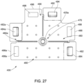
- the tee intersection connector 400 of the concrete slab joint forming system includes: (a) a load transfer corner tongue former 410; and (b) a load transfer corner lip former 460 connected to the top of the load transfer corner tongue former 410.
- the load transfer corner tongue former 410 and the load transfer lip former 460 are configured to form an intersection area for two or three joint formers 100.
- the tee intersection connector 400 is molded from a polymer. It should be appreciated that this tee intersection connector 400 can be made from other suitable materials in accordance with the present disclosure.
- this tee intersection connector 400 is a single monolithically formed piece that includes the load transfer corner tongue former 410 and the load transfer corner lip former 460. In other embodiments, the load transfer corner tongue former 410 and the load transfer corner lip former 460 or parts thereof can be separately formed and connected together.
- the load transfer corner tongue former 410 includes upright vertically extending dividers 412a, 412b, and 412c that form two sections 420a and 420b.
- the dividers 412a, 412b, and 412c are connected by a wall connector 425a.
- the wall connector 425a defines an upright vertically extending substrate fastener receiver (not labeled) that is shaped, sized, and otherwise configured to receive a fastener (not shown) that connects the tee intersection connector 400 to a substrate (not shown) on which the concrete slabs formed using the tee intersection connector 400 will be positioned.
- the section 420a extends outwardly in a first direction from the wall connector 425a and partially forms (with divider 412b) a slab concrete receipt pocket 438a that is wider at its opening, narrower at its innermost points, and is inwardly tapered from its opening to its innermost points.
- section 420c extends outwardly in a second direction from the wall connector 425b and partially forms (with divider 412b) a slab concrete receipt pocket 438b that is wider at its opening, narrower at its innermost points, and is inwardly tapered from its opening to its innermost points.
- the openings of the first and second slab concrete receipt pockets 438a and 438b thus face in two different directions.
- the sections 420a and 420b each are of the same height in this example embodiment. It should be appreciated that the height of the sections can vary in accordance with the present disclosure. In various different example embodiments, the height is 2.75 inches (6.985 cms), 3.75 inches (9.525 cms), 5.5 inches (13.97 cms), or 7.5 inches (19.05 cms).
- the sections 420a and 420b have the same depth in this example embodiment. It should be appreciated that the depths of the section can vary in accordance with the present disclosure.
- the load transfer lip former 460 includes a central section 470, a first end connection section 480, a second end connection section 490, and a third end connection section 480a each of which are connected to the top of the divider 412a, 412b, and 412c.
- the central section 470 is attached to the top of the dividers 412a, 412a, and 412c.
- the central section 470 includes top and bottom surfaces (not labeled) that are flat (or substantially flat) and extend in parallel (or substantially parallel) planes to one another in this illustrated example embodiment.
- the central section 470 includes two sections (not labeled) that correspond with the sections 420a and 420b.
- each of the sections 420a and 420b and define a plurality of spaced-apart air release openings (not labeled) that each extend from the bottom surface of the central section 470 to the top surface of the central section 470.
- These air release openings enable air caught in the concrete under the load transfer lip former 460 to escape through such openings.
- the first end connection section 480 includes top and bottom surfaces (not labeled).
- the first end connection section 480 includes a locking member portion 482 and a locking member receipt portion 486.
- the locking member portion 482 includes an upwardly extending locking member 484 (which is this example embodiment is an upwardly extending locking tab).
- the locking member receipt portion 486 defines a locking member receipt opening 488 configured to securely but releasably receive a locking member (and in this example embodiment an upwardly extending locking tab).
- the second end connection section 490 includes top and bottom surfaces (not labeled).
- the second end connection section 490 includes a locking member portion 492 and a locking member receipt portion 496.
- the locking member portion 492 includes an upwardly extending locking member 494 (which is this example embodiment is an upwardly extending locking tab).
- the locking member receipt portion 486 defines a locking member receipt opening 498 configured to securely but releasably receive a locking member (and in this example embodiment an upwardly extending locking tab).
- the third end connection section 480a includes top and bottom surfaces (not labeled).
- the third end connection section 480a includes a locking member portion 482a and a locking member receipt portion 486a.
- the locking member portion 482a includes an upwardly extending locking member 484a (which is this example embodiment is an upwardly extending locking tab).
- the locking member receipt portion 486a defines a locking member receipt opening 488a configured to securely but releasably receive a locking member (and in this example embodiment an upwardly extending locking tab).
- first, second, and third end connection sections 480, 480a, and 490 are each configured to be connected to an end of a joint former 100 or to an extension connector 200. This enables two, or three joint formers 100 or extension connectors 200 to be connected to each other and extend in multiple different directions.
- the lip former 460 can include central crack initiators (not labeled) in the top surfaces of the central section 470.
- each tee intersection connector 400 is positionable at an area where a contraction joint (or in certain instances a construction joint) will be formed between adjacent concrete slabs.
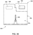
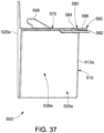
- the end connector 500 of the concrete slab joint forming system includes: (a) a load transfer corner tongue former 510; and (b) a load transfer corner lip former 560 connected to the top of the load transfer corner tongue former 510.
- the load transfer corner tongue former 510 and the load transfer lip former 560 are configured to form an end area for a joint former 100.
- this end connector 500 is molded from a polymer. It should be appreciated that this end connector 500 can be made from other suitable materials in accordance with the present disclosure.
- this end connector 500 is a single monolithically formed piece that includes the load transfer corner tongue former 510 and the load transfer corner lip former 560. In other embodiments, the load transfer corner tongue former 510 and the load transfer corner lip former 560 or parts thereof can be separately formed and connected together.
- the load transfer corner tongue former 510 includes an upright vertically extending divider 512a that form two sections 520a and 520b.
- the divider 512a is connected to an upright vertically extending form connector 525a.
- the form connector 525a defines a horizontally extending fastener receivers (not labeled) that are shaped, sized, and otherwise configured to receive fasteners (not shown) that connects end connector 500 to formwork (not shown).
- the section 520a extends outwardly in a first direction from the form connector 525a and forms a slab concrete receipt pocket 538a that is wider at its opening, narrower at its innermost points, and is inwardly tapered from its opening to its innermost points.
- section 520b extends outwardly in a second direction from the form connector 525b and forms a slab concrete receipt pocket 538b that is wider at its opening, narrower at its innermost points, and is inwardly tapered from its opening to its innermost points.
- the openings of the first and second slab concrete receipt pockets 538a and 538b thus face in different directions.
- the sections 520a and 520b each are of the same height in this example embodiment. It should be appreciated that the height of the sections can vary in accordance with the present disclosure. In various different example embodiments, the height is 2.75 inches (6.985 cms), 3.75 inches (9.525 cms), 5.5 inches (13.97 cms), or 7.5 inches (19.05 cms).
- the sections 520a and 520b have the same depth in this example embodiment. It should be appreciated that the depths of the section can vary in accordance with the present disclosure.
- the load transfer lip former 560 includes a central section 570 and a first end connection section 580 connected to the top of the divider 512a.
- the central section 570 is attached to the top of the divider 512a.
- the central section 570 includes top and bottom surfaces (not labeled) that are flat (or substantially flat) and extend in parallel (or substantially parallel) planes to one another in this illustrated example embodiment.
- the central section 570 includes two sections (not labeled) that correspond with the sections 520a and 520b.
- each of the sections 520a and 520b can define a plurality of spaced-apart air release openings (not shown) that each extend from the bottom surface of the central section 570 to the top surface of the central section 570. These air release openings enable air caught in the concrete under the load transfer lip former 560 to escape through such openings.
- the first end connection section 580 includes top and bottom surfaces (not labeled).
- the first end connection section 580 includes a locking member portion 582 and a locking member receipt portion 586.
- the locking member portion 582 includes an upwardly extending locking member 584 (which is this example embodiment is an upwardly extending locking tab).
- the locking member receipt portion 586 defines a locking member receipt opening 588 configured to securely but releasably receive a locking member (and in this example embodiment an upwardly extending locking tab).
- the first end connection sections 580 is configured to be connected to an end of a joint former 100 or to an extension connector 200.
- the end connector 500 can further include an upwardly extending cleat 595 that is configured for attaching a line or string to the end connector 500 such as when two opposing end connectors are attached to opposing spaced apart boards that define the ends of the formwork such as partially shown in Figure 51 .
- the line or string can be used to align the joint former 100 between the boards.
- These boards can be used as an outer perimeter for the concrete slabs to be formed within the area defined by the boards.
- the end connector 500 is positionable at end area where a contraction joint (or in certain instances a construction joint) will be formed between adjacent concrete slabs.
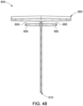
- the field cut connector 600 of the concrete slab joint forming system includes: (a) a load transfer tongue former 610; (b) a load transfer corner lip former 660 connected to the top of the load transfer tongue former 610; and (c) opposing locking lips 680 and 690.
- the load transfer tongue former 610, the load transfer lip former 660, and the locking lips 680 and 690 are configured to form a connection between two joint formers 100 such as shown in Figure 52 , where one or both of the joint formers 100 have been cut in the field during the installation process.
- this field cut connector 600 is molded from a polymer. It should be appreciated that this field cut connector 600 can be made from other suitable materials in accordance with the present disclosure.
- this field cut connector 600 is a single monolithically formed piece that includes the load transfer tongue former 610, the load transfer corner lip former 660, and the locking lips 680 and 690. In other embodiments, the load transfer tongue former 610, the load transfer corner lip former 660, and the locking lips 680 and 690 or parts thereof can be separately formed and connected together.
- the load transfer tongue former 610 includes an upright vertically extending upstanding divider 612.
- the load transfer lip former 660 is connected to the top of the divider 612.
- the locking lip 680 is connected to a first side of the divider 612 and extends therefrom below and spaced apart from the load transfer lip former 660.
- the locking lip 680 is connected to second side of the divider 612 and extends therefrom below and spaced apart from the load transfer lip former 660.
- the locking lips 680 and 690 respectively define lip former receipt pockets 685 and 698 configured to receive end portions of the lip formers of adjacent joint former 100 that are cut in the field.
- the field cut connector is positionable at an area where a contraction joint (or in certain instances a construction joint) will be formed between adjacent concrete slabs.
- Such field cut connector 600 can be employed with two concrete slab joint formers 100 such as shown in Figure 52 to connect such joint formers 100.
- the concrete slab joint former 100, the extension connector 200, the cross intersection connector 300, the tee intersection connector 400, the end connector 500, and the field cut connector 600 can be releasably connected in various different configurations.
- Figure 49 shows two joint formers 100 directly connected to each other.
- Figure 51 shows a joint former 100 directly connected to and the end connector 500 and the end connected to formwork 10.
- Figure 52 shows two joint formers 100 connected to each other by a field cut connecter 600.
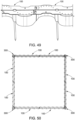
- Figure 50 shows eight joint formers 100 connected by four cross intersection connectors 300.
- the joint former 100 is secured to a substrate (not shown) by fasteners (such as shown in Figure 49 ) in the desired location of the contraction joint.
- the concrete slabs 1000 and 2000 are poured on opposites side of the joint former 100 such that: (1) the concrete extends into the opposing (such as pockets 138b to 138f and pockets 148a to 148f); (2) the air release openings in the segments of the lip former 160 (such as segments 173b to 173g and segments 174a to 174f) enable any air trapped under the lip former 160 to escape; and (3) the concrete then extends over the lip former 160 to the desired height of the concrete slabs 1000 and 2000.
- the concrete starts to cure and harden a cut is formed in the concrete down from the top surface of the concrete to the top surface of the lip former 160.
- the concrete cures and hardens the concrete slabs may separate to a certain degree along the cut line.
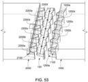
- concrete slab 1000 will include lip 1100, spaced apart tongues 1200a, 1200b, 1200c, 1200d, and 1200e, and spaced apart tongue receipt areas (not labeled) between such tongues.
- concrete slab 2000 will include lip 2100, spaced apart tongues 2200a, 2200b, 2200c, 2200d, and 2200e, and spaced apart tongue receipt areas (not labeled) between such tongues.
- Figures 53 and 54 show the slabs 1000 and 2000 substantially further apart then they would actually separate solely to illustrated the respective tongues of the concrete slabs 1000 and 2000.
- the spaced apart tongues 1200a, 1200b, 1200c, 1200d, and 1200e of concrete slab 1000 would substantially extend in the pockets of the concrete slab 2000 and under the lip 2100 of the concrete slab 2000.
- the spaced apart tongues 2200a, 2200b, 2200c, 2200d, 2200e, and 2200f of concrete slab 2000 would substantially extend in the pockets of the concrete slab 1000 and under the lip 1100 of the concrete slab 1000.
- Figure 57 shows an alternative use of the joint former 100 of the present disclosure.
- the joint former 100 is used with a joint edge assembly 5000 configured to protect the joint between concrete slabs.
- a joint edge assembly 5000 are described in U.S. Patent Nos. 6,775,952 and 8,302,359 .
- Various joint edge assemblies enable the joint edges to both self-open with respect to the opposite joint edge as the adjacent concrete slabs shrink during curing or hardening.
- the joint edge assembly 5000 protects the upper adjacent edges of the concrete slabs from damage that can occur when the joint opening creates a discontinuity in the concrete floor surface that can cause the wheels of a vehicle (such as a forklift truck) to impact the upper edges of the adjacent concrete slabs that form the joint.
- joint spalling This damage to the edges of concrete slabs is commonly referred to as joint spalling.
- Joint spalling can interrupt the normal working operations of a facility by slowing down forklift and other truck traffic, and/or causing damage to trucks and the carried products. Severe joint spalling and uneven joints can cause loaded forklift trucks to overturn (which of course is dangerous to people in those facilities). Joint spalling can also be expensive and time consuming to repair.
- the joint edge assembly 5000 can be attached to the joint former 100 using suitable fasteners (not shown that are inserted through the above described spaced-apart edge member attachment openings in the lip former 160 of the joint former 100.
- Figure 58 shows an alternative use of the joint former 100 of the present disclosure.
- the joint former 100 is used with formwork 6000 for forming a construction joint.
- the vertical extending sections (not labeled) of the formwork 6000 can extend into the plurality of spaced-apart formwork receipt areas 178a, 178b, 178c, 178d, 178e, 178f, 178g, 178h, 178i, 178j, 178k, and 1781 of the upper lip former 160 of the joint former 100, as mentioned above.
- This enables the horizontally extending member (not labeled) of the formwork 6000 to be positioned directly adjacent to the central axis of the joint former.
- none of the concrete slab joint formers, the extension connectors, the cross intersection connectors, the tee intersection connectors, the end connectors, and the field cut connectors include any anchors that extend into the adjacent concrete slabs.
- the concrete slab joint formers and/or the extension connectors can include alternatively configured load transfer tongue formers.
- the one or more of the sections or segments thereof can be straight, differently curved, differently rounded, trapezoidal, irregular in the wave pattern or amplitude, or otherwise formed.
- concrete slab joint former can be formed from two longitudinally adjacent separable elongated load transfer tongue formers and two longitudinally adjacent separate elongated load transfer lip formers respectively connected to the tops of the load transfer tongue formers.
- each of the concrete slab joint former can include one or more anchors that extend into the respective concrete slabs.
- the extension connectors, the cross intersection connectors, the tee intersection connectors, the end connectors, and the field cut connectors can be similarly formed from multiple sections.
- one or more height adjustment members can be connected to or used with the concrete slab joint formers, the extension connectors, the cross intersection connectors, the tee intersection connectors, the end connectors, and the field cut connectors.
Landscapes
- Engineering & Computer Science (AREA)
- Architecture (AREA)
- Civil Engineering (AREA)
- Structural Engineering (AREA)
- Physics & Mathematics (AREA)
- Electromagnetism (AREA)
- On-Site Construction Work That Accompanies The Preparation And Application Of Concrete (AREA)
Abstract
Description
- Various concrete floors and roadways include a series of separate individually poured or cast-in-place concrete slabs that are referred to herein as "concrete slabs." Various known issues with such concrete slabs relate to the joint between adjacent concrete slabs, the relative movements of adjacent concrete slabs when loads are placed on the concrete slabs, and the opening that forms between adjacent concrete slabs at the joint.
- Two types of joints are often used for concrete slabs. Construction joints are often used between separately individually poured adjacent concrete slabs (that are poured at sequential times). Contraction joints (which are sometimes called control joints) are often used for simultaneously poured adjacent concrete slabs. Contraction joints are often partially formed by vertically cutting a larger concrete slab at a desired location of the contraction joint to form the separate adjacent concrete slabs. The vertical cut often extends approximately one third of the way through the depth of the concrete. When the larger concrete slab cracks along the cut, the respective concrete slabs are able to separate. Contraction joints are thus often used to control natural cracking in concrete slabs from stresses caused by concrete shrinkage, thermal contraction, moisture or thermal gradients within the concrete, and/or various external forces on the concrete slabs.
- Freshly poured concrete shrinks as it cures and hardens due to the chemical reaction that occurs between the cement and water. As the concrete shrinks, stress accumulates in the concrete. Therefore, the joint between two adjacent concrete slabs needs to be able to open to enable such shrinkage of each of the individual concrete slabs without damaging the concrete slabs and while maintaining the integrity of the joint.
- After curing and hardening, adjacent concrete slabs are also subject to loads that can cause the movements of the concrete slabs relative to one another. Various construction and contraction joints include load transferring dowels of various different geometries that connect adjacent concrete slabs such that the movement of one concrete slab causes the movement of the adjacent concrete slab. In other words, these load transferring dowels connect the adjacent concrete slabs such that they substantially move together when a load is placed on one of the adjacent concrete slabs.
- There is a continuing need to develop new and better systems, apparatus, and methods for forming joints between adjacent concrete slabs.
- Various embodiments of the present disclosure provide concrete slab joint forming systems and methods of using such concrete slab joint forming systems for forming joints between adjacent concrete slabs.
- In various embodiments of the present disclosure, the concrete slab joint forming system includes: (1) a concrete slab joint former, (2) an extension connector, (3) a cross intersection connector, (4) a tee intersection connector, (5) an end connector, (6) a field cut connector, and/or (7) any combination of any quantity of these components (1) to (6). Each of the extension connector, the cross intersection connector, the tee intersection connector, and the field cut connector are connectable to one or more concrete slab joint formers or extension connectors. The end connector is connectable to one concrete slab joint former or to one extension connector. One or more of each of the extension connector, the cross intersection connector, the tee intersection connector, the end connector, and the field cut connector are selectively usable with one or more of the concrete slab joint formers and one or more extension connectors to form one or more joints for concrete slabs and the respective concrete slabs themselves.
- The concrete slab joint forming system of various embodiments of the present disclosure reduce: (1) the quantity of components for forming concrete slab, (2) the weight of the components for forming concrete slabs, (3) the complexity of the assembly and installation of the components for forming concrete slabs, and/or (4) the assembly and installation time for the components needed for forming concrete slabs, as compared to various known concrete slab forming and load transfer apparatus.
- Additional features and advantages of the present disclosure are described in, and will be apparent from, the following Detailed Description and the Figures.
-
-
Figure 1 is a top perspective view of a concrete slab joint former of one example embodiment of the concrete slab joint forming system of the present disclosure. -
Figure 2 is a bottom perspective view of the concrete slab joint formerFigure 1 . -
Figure 3 is a top view of the concrete slab joint former ofFigure 1 . -
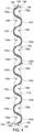
Figure 4 is a bottom view of the concrete slab joint former ofFigure 1 . -
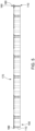
Figure 5 is a first side view of the concrete slab joint former ofFigure 1 . -
Figure 6 is a second side view of the concrete slab joint former ofFigure 1 . -
Figure 7 is an enlarged first end view of the concrete slab joint former ofFigure 2 . -
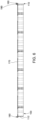
Figure 8 is an enlarged second end view of the concrete slab joint former ofFigure 2 . -
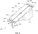
Figure 9 is a top perspective view of an extension connector of one example embodiment of the concrete slab joint forming system of the present disclosure. -
Figure 10 is a bottom perspective view of the extension connector ofFigure 9 . -
Figure 11 is a top view of the extension connector ofFigure 9 . -
Figure 12 is a bottom view of the extension connector ofFigure 9 . -
Figure 13 is a first side view of the extension connector ofFigure 9 . -
Figure 14 is a second side view of the extension connector ofFigure 9 . -
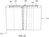
Figure 15 is an enlarged first end view of the extension connector ofFigure 9 . -
Figure 16 is an enlarged second end view of the extension connector ofFigure 9 . -
Figure 17 is a top perspective view of a cross intersection connector of one example embodiment of the concrete slab joint forming system of the present disclosure. -
Figure 18 is a bottom perspective view of the cross intersection connector ofFigure 17 . -
Figure 19 is a top view of the cross intersection connector ofFigure 17 . -
Figure 20 is a bottom view of the cross intersection connector ofFigure 17 . -
Figure 21 is a first side view of the cross intersection connector ofFigure 17 . -
Figure 22 is a second side view of the cross intersection connector ofFigure 17 . -
Figure 23 is a first end view of the cross intersection connector ofFigure 17 . -
Figure 24 is a second end view of the cross intersection connector ofFigure 17 . -
Figure 25 is a top perspective view of a tee intersection connector of one example embodiment of the concrete slab joint forming system of the present disclosure. -
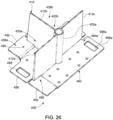
Figure 26 is a bottom perspective view of the tee intersection connector ofFigure 25 . -
Figure 27 is a top view of the tee intersection connector ofFigure 25 . -
Figure 28 is a bottom view of the tee intersection connector ofFigure 25 . -
Figure 29 is a first side view of the tee intersection connector ofFigure 25 . -
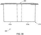
Figure 30 is a second side view of the tee intersection connector ofFigure 25 . -
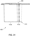
Figure 31 is a first end view of the tee intersection connector ofFigure 25 . -
Figure 32 is a second end view of the tee intersection connector ofFigure 25 . -
Figure 33 is a top perspective view of an end connector of one example embodiment of the concrete slab joint forming system of the present disclosure. -
Figure 34 is a bottom perspective view of the end connector ofFigure 33 . -
Figure 35 is a top view of the end connector ofFigure 33 . -
Figure 36 is a bottom view of the end connector ofFigure 33 . -
Figure 37 is a first side view of the end connector ofFigure 33 . -
Figure 38 is a second side view of the end ofFigure 33 . -
Figure 39 is a first end view of the end connector ofFigure 33 . -
Figure 40 is a second end view of the end connector ofFigure 33 . -
Figure 41 is a top perspective view of a field cut connector of one example embodiment of the concrete slab joint forming system of the present disclosure. -
Figure 42 is a bottom perspective view of the field cut connector ofFigure 33 . -
Figure 43 is a top view of the field cut connector ofFigure 41 . -
Figure 44 is a bottom view of the field cut connector ofFigure 41 . -
Figure 45 is a first side view of the field cut connector ofFigure 41 . -
Figure 46 is a second side view of the field cut ofFigure 41 . -
Figure 47 is a first end view of the field connector ofFigure 41 . -
Figure 48 is a second end view of the filed cut connector ofFigure 41 . -
Figure 49 is a fragmentary top perspective view of two concrete slab joint formers ofFigure 1 having their respective ends connected. -
Figure 50 is a top view of eight concrete slab joint formers ofFigure 1 and four cross intersection connector ofFigure 17 suitably connected. -
Figure 51 is a fragmentary top perspective view of one concrete slab joint former ofFigure 1 connected to an end connector ofFigure 33 that is in turn connected to formwork. -
Figure 52 is a fragmentary top perspective view of two concrete slab joint formers ofFigure 1 their respective ends connected by a field cut connector. -
Figure 53 is a top perspective view of the concrete slab joint former ofFigure 1 shown positioned between two adjacent concrete slabs (shown in fragmentary), and illustrating the structures in the adjacent concrete slabs formed by the concrete slab joint former. -
Figure 54 is a fragmentary top perspective view of the concrete slab joint former ofFigure 1 shown positioned between two adjacent concrete slabs, and illustrating the structures in the adjacent concrete slabs formed by the concrete slab joint former. -
Figure 55 is a fragmentary end cross-sectional view of the concrete slab joint former ofFigure 1 shown positioned between two adjacent concrete slabs, and illustrating the structures in the adjacent concrete slabs formed by the concrete slab joint former. -
Figure 56 is a fragmentary end cross-sectional view of the concrete slab joint former ofFigure 1 shown positioned between two adjacent concrete slabs, and illustrating the structures in the adjacent concrete slabs formed by the concrete slab joint former. -
Figure 57 is a fragmentary end view of an upright wall of an example edge member assembly attached above and to the concrete slab joint former ofFigure 1 . -
Figure 58 is a fragmentary end view of the concrete slab joint former ofFigure 1 shown positioned with formwork for forming a construction joint. - While the features, devices, and apparatus described herein may be embodied in various forms, the drawings show and the specification describe certain exemplary and non-limiting embodiments. Not all of the components shown in the drawings and described in the specification may be required, and certain implementations may include additional, different, or fewer components. Variations in the arrangement and type of the components; the shapes, sizes, and materials of the components; and the manners of connections of the components may be made without departing from the spirit or scope of the claims. Unless otherwise indicated, any directions referred to in the specification reflect the orientations of the components shown in the corresponding drawings and do not limit the scope of the present disclosure. Further, terms that refer to mounting methods, such as mounted, attached, connected, and the like, are not intended to be limited to direct mounting methods but should be interpreted broadly to include indirect and operably mounted, attached, connected and like mounting methods. This specification is intended to be taken as a whole and interpreted in accordance with the principles of the present disclosure and as understood by one of ordinary skill in the art.
- Various embodiments of the present disclosure provide concrete slab joint forming systems and methods of using such concrete slab joint forming systems for forming joints between adjacent concrete slabs and the concrete slabs themselves. For brevity, the concrete slab joint forming system may sometimes be referred to herein as the joint forming system or the system. Such abbreviations are not meant to limit the scope of the present disclosure.
- In various embodiments of the present disclosure provide, the concrete slab joint forming systems and methods are dowel-less, and thus do not include any additional dowels that extend into the adjacent concrete slabs. In various embodiments, the lips and tongues of the adjacent concrete slabs perform the functions previously performed by such additional dowels.
- One example embodiment of the concrete slab joint forming system of the present disclosure is shown in
Figures 1 to 56 . This example embodiment of the concrete slab joint forming system includes a concrete slab joint former 100 shown inFigures 1 to 8 , and various different connectors shown inFigures 9 to 48 . The various different connectors in this example embodiment include: (a) anextension connector 200 shown inFigures 9 to 16 , (b) across intersection connector 300 shown inFigures 17 to 24 , (c) atee intersection connector 400 shown inFigures 25 to 32 , (d) anend connector 500 shown inFigures 33 to 40 , and (e) afield cut connector 600 shown inFigures 41 to 48 . The concrete slab joint former 100 can be employed with or without any of theconnectors joint formers 100 can be employed with each other and with or without one or more of any of theconnectors - Turning now to
Figures 1 to 8 , in this illustrated example embodiment, this concrete slab joint former 100 includes: (a) an elongated load transfer tongue former 110; and (b) an elongated load transfer lip former 160 connected to the top of the load transfer tongue former 110. The load transfer tongue former 110 and the load transfer lip former 160 are configured to form opposingload transfer lips adjacent slabs load transfer tongues concrete slabs Figures 53 ,54, 55, and 56 , and as further discussed below. In various embodiments, the lips rest of the respective concrete slabs rest on the respective opposing tongues of the concrete slabs. Such opposing load transfer lips and opposing load transfer tongues are configured to transfer forces (such as but not limited to vertical forces) between the adjacent concrete slabs without the use of additional dowels as further explained below. In various circumstances, the concrete slab joint former 100 may additionally itself function as a dowel for assisting in the transfer of such forces between adjacent concrete slabs. The concrete slab joint former 100 may sometimes be referred to herein as the joint former 100 for brevity. - In the illustrated example embodiment, the concrete slab joint former 100 is molded from a polymer. It should be appreciated that the concrete slab joint former 100 can be made from other suitable materials in accordance with the present disclosure. In this illustrated example embodiment, this concrete slab joint former 100 is a single monolithically formed piece that includes the elongated load transfer tongue former 110 and the elongated load transfer lip former 160. In other embodiments, the elongated load transfer tongue former 110 and the elongated load transfer lip former 160 or parts thereof can be separately formed and connected together.
- The load transfer tongue former 110 includes an upright vertically extending
waveform 112 having multiple tongue formingconcrete receipt sections waveform 112 has a longitudinally extending central axis (not shown). Each of thesections section 120a is connected tosection 120b bysection connector 125a,section 120b is connected tosection 120c bysection connector 125b,section 120c is connected tosection 120d bysection connector 125c,section 120d is connected tosection 120e bysection connector 125e,section 120e is connected tosection 120f bysection connector 125e, andsection 120f is connected tosection 120g bysection connector 125f. Each of thesection connectors Figure 49 ) that connects the concrete slab joint former 100 to a substrate (not shown) on which the concrete slabs formed using the joint former 100 will be positioned. - In this example embodiment, the
sections concrete receipt segments concrete receipt segments sections - In this example embodiment, the
section 120a has a tongue formingconcrete receipt segment 140a that extends outwardly in the second direction from the central axis. Likewise, in this example embodiment, thesection 120g has a tongue formingconcrete receipt segment 130g that extends outwardly in the first opposite direction from the central axis. - The plurality of tongue forming
concrete receipt segments - The plurality of the tongue forming
concrete receipt segments concrete receipt pockets concrete receipt pockets - The plurality of spaced apart first slab concrete receipt pockets 138b, 138c, 138d, 138e, 138f, and 138g alternate with the plurality of spaced apart second slab
concrete receipt pockets - The
sections waveform 112 is 2.75 inches (6.985 cms), 3.75 inches (9.525 cms), 5.5 inches (13.97 cms), or 7.5 inches (19.05 cms). These example heights, can for example be used with concrete slabs have heights (generally referred to as thicknesses) of between 5 inches (12.7 cms) and 16 inches (40.64 cms). The heights will thus generally depend on the heights of the concrete slabs in various embodiments. - All of the segments of the
sections waveform 112 is 5 inches (12.7 cms), however the depth can depend on the desired depth of the lips and tongues of the concrete slabs. - All of the segments of the
sections waveform 112. It should be appreciated that the amplitude of the waveform can vary in accordance with the present disclosure. It should also be appreciated that a single waveform can have a varying amplitude in accordance with the present disclosure. - It should further be appreciated that the quantity of sections of the
waveform 112 and thus the quantity of segments of thewaveform 112 can vary in accordance with the present disclosure, such as based on the length of the concrete slab joint former 100. In various example embodiments, thewaveform 112 is 69 inches (175.26 cms). It should thus be appreciated that thewaveform 112 can be made in other suitable sizes, shapes, and configurations in accordance with the present disclosure. - The load transfer lip former 160 includes an elongated
central section 170, a firstend connection section 180, and a secondend connection section 190, each of which are connected to the top of thewaveform 112 in this example embodiment. In other embodiments, only the elongatedcentral section 170 is connected to the top of thewaveform 112 and the firstend connection section 180 and the secondend connection section 190 are connected to opposite ends of thewaveform 112 and extend in opposing directions from thewaveform 112. - The
central section 170 is connected to the top of thewaveform 112 and extends substantially the entire length of thewaveform 112. Thecentral section 170 includes horizontally extending top andbottom surfaces central section 170 includes a plurality ofsections sections waveform 112. The plurality ofsections segments segments waveform 112. The plurality ofsections segments segments waveform 112. - In this example embodiment, each of the
segments bottom surface 171b of thecentral section 170 to thetop surface 171t of thecentral section 170. These air release openings enable air caught in the concrete that extends into thepockets - In this example embodiment, the segments also respectively define a plurality of spaced-apart edge member attachment openings (not individually labeled) that each extend from the
bottom surface 171b of thecentral section 170 to thetop surface 171t of thecentral section 170 that enable the bottom upright wall of an edge member assembly to be attached (by suitable fasteners (not shown)) above and to the load transfer lip former 160 and thus the concrete slab joint former 100.Figure 57 shows an example of abottom upright wall 5100 of anedge member assembly 5000 attached (by suitable fasteners (not shown)) above and to a load transfer lip former 160 and thus the concrete slab joint former 100. Thus, the concrete slab joint former 100 of the present disclosure can additionally function with a joint edge assembly to form a construction joint between two adjacent slabs. - In this example embodiment, the segments also respectively define a plurality of spaced-apart
formwork receipt areas Figure 58 ) for forming construction joints between adjacent concrete slabs. Specifically, the concrete slab joint former 100 can be used with formwork for construction joints where one of the concrete slabs is poured and hardened before the adjacent concrete slab. In the illustrated example embodiment ofFigure 58 , a horizontally extending two-by-four 6100 is positioned over the lip former and attached to thestakes 6200. The indented spaced-apartformwork receipt areas waveform 112 for forming the outer side surface of the concrete slab. - The first
end connection section 180 includes top and bottom surfaces (not labeled). The firstend connection section 180 includes a lockingmember portion 182 and a lockingmember receipt portion 186. The lockingmember portion 182 includes an upwardly extending locking member 184 (which is this example embodiment is an upwardly extending locking tab). The lockingmember receipt portion 186 defines a locking member receipt opening 188 configured to securely but releasably receive a locking member (and in this example embodiment an upwardly extending locking tab). - Likewise, the second
end connection section 190 includes top and bottom surfaces (not labeled). The secondend connection section 190 includes a lockingmember portion 192 and a lockingmember receipt portion 196. The lockingmember portion 192 includes an upwardly extending locking member 194 (which is this example embodiment is an upwardly extending locking tab). The lockingmember receipt portion 186 defines a locking member receipt opening 198 configured to securely but releasably receive a locking member (and in this example embodiment an upwardly extending locking tab). - The first
end connection section 180 and the secondend connection section 190 are thus configured with the lockingmember portion 182 and the lockingmember receipt portion 186 oppositely positioned from the lockingmember portion 192 and the lockingmember receipt portion 196. This enables two the concrete slab joint former 100 to be connected to each other end to end such as shown inFigure 49 . - This also enables either end of the concrete slab joint former 100 to be connected to any of the
extension connector 200, thecross intersection connector 300, thetee intersection connector 400, and theend connector 500 such as shown inFigures 49, 50 , and51 . - The elongated lip former 160 further defines a longitudinally and upwardly extending
central crack initiator 162 in the top surfaces of thecentral section 170, the firstend connection section 180, and the secondend connection section 190. Thiscrack initiator 162 facilitates alignment of the joint former and an indication to the installer for alignment purposes as to where the cut in the concrete should be made to form the contraction joint between and to form the adjacent concrete slabs. Thiscrack initiator 162 further facilitates the forming of the crack or separation in the concrete to form the separate adjacent concrete slabs. Specifically, when the concrete is cut from the top to form the location of the separation between the two concrete slabs and to form the contraction joint, the crack initiator can provide a weakened area in the concrete that will assist in forming the separation in the correct location. - It should thus be appreciated from the above and as shown in
Figures 53 ,54, 55, and 56 that in this illustrated example embodiment of present disclosure, each concrete slab joint former 100 is positionable at an area where a contraction joint will be formed between adjacent concrete slabs, as further discussed below. - Turning now to
Figures 9 to 16 , in this illustrated example embodiment, theextension connector 200 of the concrete slab joint forming system is substantially similar to the concrete slab joint former 100 but is substantially shorter in length. Theextension connector 200 includes: (a) a load transfer tongue former 210; and (b) a load transfer lip former 260 connected to the top of the load transfer tongue former 210. The load transfer tongue former 210 and the load transfer lip former 260 are configured to form opposing load transfer lips and opposing load transfer tongues in the adjacent concrete slabs as further discussed below and such that the opposing load transfer lips and opposing load transfer tongues are configured to transfer vertical forces between the adjacent concrete slabs without the use of dowels as further explained below. - In the illustrated example embodiment, the
extension connector 200 is molded from a polymer. It should be appreciated that theextension connector 200 can be made from other suitable materials in accordance with the present disclosure. In this illustrated example embodiment, thisextension connector 200 is a single monolithically formed piece that includes the load transfer tongue former 210 and the load transfer lip former 260. In other embodiments, the load transfer tongue former 210 and the load transfer lip former 260 or parts thereof can be separately formed and connected together. - The load transfer tongue former 210 includes an upright vertically extending
waveform 212 having two tongue formingconcrete receipt sections waveform 212 has a longitudinally extending central axis (not shown). Thesections section connector 225a. Thesection connector 225a defines an upright vertically extending substrate fastener receiver (not labeled) that is shaped, sized, and otherwise configured to receive a fastener (such as shown inFigure 49 ) that connects theextension connector 200 to a substrate (not shown) on which the concrete slabs partially formed by theextension connector 200 will be positioned. - In this example embodiment, the
section 220a has a tongue formingconcrete receipt segment 230a that extends outwardly in a first direction from the central axis. The tongue formingconcrete receipt segment 230a forms a slabconcrete receipt pocket 238a that is wider at its opening, narrower at its innermost points, and is inwardly tapered from its opening to their innermost points. - Likewise, in this example embodiment, the
section 220b has a tongue formingconcrete receipt segment 240b that extends outwardly in a second opposite direction from the central axis. The tongue formingconcrete receipt segment 240b forms a second slabconcrete receipt pocket 248b that is wider at its opening, narrower at its innermost points, and is inwardly tapered from its openings to its innermost points. - The opening of the first slab
concrete receipt pocket 238a faces in an opposite direction as the opening of the second slabconcrete receipt pocket 248b. - The
sections waveform 212 is 2.75 inches (6.985 cms), 3.75 inches (9.525 cms), 5.5 inches (13.97 cms), or 7.5 inches (19.05 cms). - The segments of the
sections waveform 212 is 5 inches (12.7 cms), however the depth can depend on the desired depth of the lips and tongues of the concrete slabs. - The segments of the
sections waveform 212. - It should be appreciated that the quantity of sections of the
waveform 212 and thus the quantity of segments of thewaveform 212 can vary in accordance with the present disclosure, such as based on the length of theextension connector 200. - In this example embodiment, the
waveform 212 is 12 inches (30.48 cms). It should also be appreciated that thewaveform 212 can be made in other suitable sizes, shapes, and configurations in accordance with the present disclosure. - The load transfer lip former 260 includes a
central section 270, a firstend connection section 280, and a secondend connection section 290, each of which are connected to the top of thewaveform 212. - The
central section 270 is attached to the top of thewaveform 212 and extends substantially the entire length of thewaveform 212. - The
central section 270 includes top and bottom surfaces (not labeled) that are flat (or substantially flat) and extend in parallel (or substantially parallel) planes to one another in this illustrated example embodiment. Thecentral section 270 includes a twosections sections waveform 212. Thesections segments segments 240a and 240b of thewaveform 212. - In this example embodiment, each of the segments 240a and define a plurality of spaced-apart air release openings (not labeled) that each extend from the bottom surface 271b of the
central section 270 to the top surface 271t of thecentral section 270. These air release opening enable air caught in the concrete under the load transfer lip former 260 to escape through such openings. - Although not shown, the segments can define a plurality of spaced-apart edge member attachment openings that enable edge members to be attached above and to the load transfer lip former 260 and thus the
extension connector 200. - Although not shown, the segments can define a plurality of spaced-apart formwork receipt areas that can be used to receive upright formwork members.
- The first
end connection section 280 includes top and bottom surfaces (not labeled). The firstend connection section 280 includes a lockingmember portion 282 and a lockingmember receipt portion 286. The lockingmember portion 282 includes an upwardly extending locking member 284 (which is this example embodiment is an upwardly extending locking tab). The lockingmember receipt portion 286 defines a locking member receipt opening 288 configured to securely but releasably receive a locking member (and in this example embodiment an upwardly extending locking tab). - Likewise, the second
end connection section 290 includes top and bottom surfaces (not labeled). The secondend connection section 290 includes a lockingmember portion 292 and a lockingmember receipt portion 296. The lockingmember portion 292 includes an upwardly extending locking member 294 (which is this example embodiment is an upwardly extending locking tab). The lockingmember receipt portion 286 defines a locking member receipt opening 298 configured to securely but releasably receive a locking member (and in this example embodiment an upwardly extending locking tab). - The first
end connection section 280 and the secondend connection section 290 are configured with the lockingmember portion 282 and the lockingmember receipt portion 286 are oppositely positioned from the lockingmember portion 292 and the lockingmember receipt portion 296. This enables twoextension connectors 200 to be connected to each other end to end, and also enables either end of theextension member 200 to be connected to either end of the concrete slab joint former 100, and either end to be connected to any of thecross intersection connector 300, thetee intersection connector 400, or theend connector 500, such as further discussed below. - The lip former 260 further defines a longitudinally extending central crack initiator 262 in the
central section 270, the firstend connection section 280, and the secondend connection section 290. This crack initiator 262 assists in facilitating the formation of the crack between the adjacent concrete slabs when the installer cuts the concrete from the top to form the contraction joint between the two concrete slabs. - It should thus be appreciated from the above that in this illustrated example embodiment of present disclosure, each extension connector is positionable at an area where a contraction joint will be formed between adjacent concrete slabs, as further discussed below.
Such extension connector 200 can be employed with one or more concrete slab joint former 100 to extend such concrete slab joint former 100.Such extension connector 200 can also be employed with one or moreother extension connectors 200. - Turning now to
Figures 17 to 24 , in this illustrated example embodiment, thecross intersection connector 300 of the concrete slab joint forming system includes: (a) a load transfer corner tongue former 310; and (b) a load transfer corner lip former 360 connected to the top of the load transfer corner tongue former 310. The load transfer corner tongue former 310 and the load transfer lip former 360 are configured to form an intersection area for two, three, or fourjoint formers 100. - In the illustrated example embodiment, the
cross intersection connector 300 is molded from a polymer. It should be appreciated that thiscross intersection connector 300 can be made from other suitable materials in accordance with the present disclosure. In this illustrated example embodiment, thiscross intersection connector 300 is a single monolithically formed piece that includes the load transfer corner tongue former 310 and the load transfer corner lip former 360. In other embodiments, the load transfer corner tongue former 310 and the load transfer corner lip former 360 or parts thereof can be separately formed and connected together. - The load transfer corner tongue former 310 includes upright vertically extending
dividers sections dividers wall connector 325a. Thewall connector 325a defines an upright vertically extending substrate fastener receiver (not labeled) that is shaped, sized, and otherwise configured to receive a fastener (not shown) that connects thecross intersection connector 300 to a substrate (not shown) on which the concrete slabs formed using thecross intersection connector 300 will be positioned. - In this example embodiment, the
section 320a extends outwardly in a first direction from thewall connector 325a and forms a slabconcrete receipt pocket 338a that is wider at its opening, narrower at its innermost points, and is inwardly tapered from its opening to its innermost points. - Likewise, the
section 320b extends outwardly in a second direction from the wall connector 325b and forms a slabconcrete receipt pocket 338b that is wider at its opening, narrower at its innermost points, and is inwardly tapered from its opening to its innermost points. - Likewise, the
section 320c extends outwardly in a third direction from the wall connector 325c and forms a slabconcrete receipt pocket 338c that is wider at its opening, narrower at its innermost points, and is inwardly tapered from its opening to its innermost points. - Likewise, the
section 320d extends outwardly in a fourth direction from the wall connector 325d and forms a slabconcrete receipt pocket 338d that is wider at its opening, narrower at its innermost points, and is inwardly tapered from its opening to its innermost points. - The openings of the first, second, third, and fourth slab
concrete receipt pockets - The
sections - The
sections - The load transfer lip former 360 includes a
central section 370, a firstend connection section 380, a secondend connection section 390, a thirdend connection section 380a, and a fourthend connection section 390a that are connected to the top of thedividers - The
central section 370 is attached to the top of thedividers central section 370 includes top and bottom surfaces (not labeled) that are flat (or substantially flat) and extend in parallel (or substantially parallel) planes to one another in this illustrated example embodiment. Thecentral section 370 includes four sections (not labeled) that correspond with thesections - In this example embodiment, each of the
sections central section 370 to the top surface of thecentral section 370. These air release openings enable air caught in the concrete under the load transfer lip former 360 to escape through such openings. - The first
end connection section 380 includes top and bottom surfaces (not labeled). The firstend connection section 380 includes a lockingmember portion 382 and a lockingmember receipt portion 386. The lockingmember portion 382 includes an upwardly extending locking member 384 (which is this example embodiment is an upwardly extending locking tab). The lockingmember receipt portion 386 defines a locking member receipt opening 388 configured to securely but releasably receive a locking member (and in this example embodiment an upwardly extending locking tab). - Likewise, the second
end connection section 390 includes top and bottom surfaces (not labeled). The secondend connection section 390 includes a lockingmember portion 392 and a lockingmember receipt portion 396. The lockingmember portion 392 includes an upwardly extending locking member 394 (which is this example embodiment is an upwardly extending locking tab). The lockingmember receipt portion 386 defines a locking member receipt opening 398 configured to securely but releasably receive a locking member (and in this example embodiment an upwardly extending locking tab). - Likewise, the third
end connection section 380a includes top and bottom surfaces (not labeled). The thirdend connection section 380a includes a lockingmember portion 382a and a lockingmember receipt portion 386a. The lockingmember portion 382a includes an upwardly extendinglocking member 384a (which is this example embodiment is an upwardly extending locking tab). The lockingmember receipt portion 386a defines a lockingmember receipt opening 388a configured to securely but releasably receive a locking member (and in this example embodiment an upwardly extending locking tab). - Likewise, the fourth second
end connection section 390a includes top and bottom surfaces (not labeled). The fourth secondend connection section 390a includes a lockingmember portion 392a and a lockingmember receipt portion 396a. The lockingmember portion 392a includes an upwardly extending locking member 394a (which is this example embodiment is an upwardly extending locking tab). The lockingmember receipt portion 386a defines a lockingmember receipt opening 398a configured to securely but releasably receive a locking member (and in this example embodiment an upwardly extending locking tab). - As explained above, the first, second, third, and fourth
end connection sections extension connector 200. This enables two, three, or fourjoint formers 100 orextension connectors 200 to be connected to each other and extend in multiple different directions. - Similar to as described above, the lip former 360 can include central crack initiators (not labeled) in the top surfaces of the
central section 370. - It should thus be appreciated from the above that in this illustrated example embodiment of present disclosure, each
cross intersection connector 300 is positionable at an area where a contraction joint (or in certain instances a construction joint) will be formed between adjacent concrete slabs. - Turning now to
Figures 25 to 32 , in this illustrated example embodiment, thetee intersection connector 400 of the concrete slab joint forming system includes: (a) a load transfer corner tongue former 410; and (b) a load transfer corner lip former 460 connected to the top of the load transfer corner tongue former 410. The load transfer corner tongue former 410 and the load transfer lip former 460 are configured to form an intersection area for two or threejoint formers 100. - In the illustrated example embodiment, the
tee intersection connector 400 is molded from a polymer. It should be appreciated that thistee intersection connector 400 can be made from other suitable materials in accordance with the present disclosure. In this illustrated example embodiment, thistee intersection connector 400 is a single monolithically formed piece that includes the load transfer corner tongue former 410 and the load transfer corner lip former 460. In other embodiments, the load transfer corner tongue former 410 and the load transfer corner lip former 460 or parts thereof can be separately formed and connected together. - The load transfer corner tongue former 410 includes upright vertically extending
dividers sections dividers wall connector 425a. Thewall connector 425a defines an upright vertically extending substrate fastener receiver (not labeled) that is shaped, sized, and otherwise configured to receive a fastener (not shown) that connects thetee intersection connector 400 to a substrate (not shown) on which the concrete slabs formed using thetee intersection connector 400 will be positioned. - In this example embodiment, the
section 420a extends outwardly in a first direction from thewall connector 425a and partially forms (withdivider 412b) a slabconcrete receipt pocket 438a that is wider at its opening, narrower at its innermost points, and is inwardly tapered from its opening to its innermost points. - Likewise, the section 420c extends outwardly in a second direction from the wall connector 425b and partially forms (with
divider 412b) a slabconcrete receipt pocket 438b that is wider at its opening, narrower at its innermost points, and is inwardly tapered from its opening to its innermost points. - The openings of the first and second slab concrete receipt pockets 438a and 438b thus face in two different directions.
- The
sections - The
sections - The load transfer lip former 460 includes a
central section 470, a firstend connection section 480, a secondend connection section 490, and a thirdend connection section 480a each of which are connected to the top of thedivider - The
central section 470 is attached to the top of thedividers central section 470 includes top and bottom surfaces (not labeled) that are flat (or substantially flat) and extend in parallel (or substantially parallel) planes to one another in this illustrated example embodiment. Thecentral section 470 includes two sections (not labeled) that correspond with thesections - In this example embodiment, each of the
sections central section 470 to the top surface of thecentral section 470. These air release openings enable air caught in the concrete under the load transfer lip former 460 to escape through such openings. - The first
end connection section 480 includes top and bottom surfaces (not labeled). The firstend connection section 480 includes a lockingmember portion 482 and a lockingmember receipt portion 486. The lockingmember portion 482 includes an upwardly extending locking member 484 (which is this example embodiment is an upwardly extending locking tab). The lockingmember receipt portion 486 defines a locking member receipt opening 488 configured to securely but releasably receive a locking member (and in this example embodiment an upwardly extending locking tab). - Likewise, the second
end connection section 490 includes top and bottom surfaces (not labeled). The secondend connection section 490 includes a lockingmember portion 492 and a lockingmember receipt portion 496. The lockingmember portion 492 includes an upwardly extending locking member 494 (which is this example embodiment is an upwardly extending locking tab). The lockingmember receipt portion 486 defines a locking member receipt opening 498 configured to securely but releasably receive a locking member (and in this example embodiment an upwardly extending locking tab). - Likewise, the third
end connection section 480a includes top and bottom surfaces (not labeled). The thirdend connection section 480a includes a lockingmember portion 482a and a lockingmember receipt portion 486a. The lockingmember portion 482a includes an upwardly extendinglocking member 484a (which is this example embodiment is an upwardly extending locking tab). The lockingmember receipt portion 486a defines a lockingmember receipt opening 488a configured to securely but releasably receive a locking member (and in this example embodiment an upwardly extending locking tab). - As explained above, the first, second, and third
end connection sections extension connector 200. This enables two, or threejoint formers 100 orextension connectors 200 to be connected to each other and extend in multiple different directions. - Similar to as described above, the lip former 460 can include central crack initiators (not labeled) in the top surfaces of the
central section 470. - It should thus be appreciated from the above that in this illustrated example embodiment of present disclosure, each
tee intersection connector 400 is positionable at an area where a contraction joint (or in certain instances a construction joint) will be formed between adjacent concrete slabs. - Turning now to
Figures 33 to 40 , in this illustrated example embodiment, theend connector 500 of the concrete slab joint forming system includes: (a) a load transfer corner tongue former 510; and (b) a load transfer corner lip former 560 connected to the top of the load transfer corner tongue former 510. The load transfer corner tongue former 510 and the load transfer lip former 560 are configured to form an end area for a joint former 100. - In the illustrated example embodiment, this
end connector 500 is molded from a polymer. It should be appreciated that thisend connector 500 can be made from other suitable materials in accordance with the present disclosure. In this illustrated example embodiment, thisend connector 500 is a single monolithically formed piece that includes the load transfer corner tongue former 510 and the load transfer corner lip former 560. In other embodiments, the load transfer corner tongue former 510 and the load transfer corner lip former 560 or parts thereof can be separately formed and connected together. - The load transfer corner tongue former 510 includes an upright vertically extending
divider 512a that form twosections divider 512a is connected to an upright vertically extendingform connector 525a. Theform connector 525a defines a horizontally extending fastener receivers (not labeled) that are shaped, sized, and otherwise configured to receive fasteners (not shown) that connectsend connector 500 to formwork (not shown). - In this example embodiment, the
section 520a extends outwardly in a first direction from theform connector 525a and forms a slabconcrete receipt pocket 538a that is wider at its opening, narrower at its innermost points, and is inwardly tapered from its opening to its innermost points. - Likewise, the
section 520b extends outwardly in a second direction from the form connector 525b and forms a slabconcrete receipt pocket 538b that is wider at its opening, narrower at its innermost points, and is inwardly tapered from its opening to its innermost points. - The openings of the first and second slab concrete receipt pockets 538a and 538b thus face in different directions.
- The
sections - The
sections - The load transfer lip former 560 includes a
central section 570 and a firstend connection section 580 connected to the top of thedivider 512a. - The
central section 570 is attached to the top of thedivider 512a. Thecentral section 570 includes top and bottom surfaces (not labeled) that are flat (or substantially flat) and extend in parallel (or substantially parallel) planes to one another in this illustrated example embodiment. Thecentral section 570 includes two sections (not labeled) that correspond with thesections - In this example embodiment, each of the
sections central section 570 to the top surface of thecentral section 570. These air release openings enable air caught in the concrete under the load transfer lip former 560 to escape through such openings. - The first
end connection section 580 includes top and bottom surfaces (not labeled). The firstend connection section 580 includes a lockingmember portion 582 and a lockingmember receipt portion 586. The lockingmember portion 582 includes an upwardly extending locking member 584 (which is this example embodiment is an upwardly extending locking tab). The lockingmember receipt portion 586 defines a locking member receipt opening 588 configured to securely but releasably receive a locking member (and in this example embodiment an upwardly extending locking tab). - As explained above, the first
end connection sections 580 is configured to be connected to an end of a joint former 100 or to anextension connector 200. - The
end connector 500 can further include an upwardly extendingcleat 595 that is configured for attaching a line or string to theend connector 500 such as when two opposing end connectors are attached to opposing spaced apart boards that define the ends of the formwork such as partially shown inFigure 51 . The line or string can be used to align the joint former 100 between the boards. These boards can be used as an outer perimeter for the concrete slabs to be formed within the area defined by the boards. - It should thus be appreciated from the above that in this illustrated example embodiment of present disclosure, the
end connector 500 is positionable at end area where a contraction joint (or in certain instances a construction joint) will be formed between adjacent concrete slabs. - Turning now to
Figures 41 to 48 , in this illustrated example embodiment, thefield cut connector 600 of the concrete slab joint forming system includes: (a) a load transfer tongue former 610; (b) a load transfer corner lip former 660 connected to the top of the load transfer tongue former 610; and (c) opposing lockinglips lips joint formers 100 such as shown inFigure 52 , where one or both of thejoint formers 100 have been cut in the field during the installation process. - In the illustrated example embodiment, this
field cut connector 600 is molded from a polymer. It should be appreciated that thisfield cut connector 600 can be made from other suitable materials in accordance with the present disclosure. In this illustrated example embodiment, thisfield cut connector 600 is a single monolithically formed piece that includes the load transfer tongue former 610, the load transfer corner lip former 660, and the lockinglips lips - The load transfer tongue former 610 includes an upright vertically extending upstanding divider 612. The load transfer lip former 660 is connected to the top of the divider 612. The locking
lip 680 is connected to a first side of the divider 612 and extends therefrom below and spaced apart from the load transfer lip former 660. The lockinglip 680 is connected to second side of the divider 612 and extends therefrom below and spaced apart from the load transfer lip former 660. The lockinglips - The field cut connector is positionable at an area where a contraction joint (or in certain instances a construction joint) will be formed between adjacent concrete slabs. Such
field cut connector 600 can be employed with two concrete slabjoint formers 100 such as shown inFigure 52 to connect suchjoint formers 100. - As mentioned above, and as shown in
Figures 49, 50 ,51, and 52 , the concrete slab joint former 100, theextension connector 200, thecross intersection connector 300, thetee intersection connector 400, theend connector 500, and thefield cut connector 600 can be releasably connected in various different configurations. As mentioned above,Figure 49 shows twojoint formers 100 directly connected to each other. As mentioned above,Figure 51 shows a joint former 100 directly connected to and theend connector 500 and the end connected toformwork 10. As mentioned above,Figure 52 shows twojoint formers 100 connected to each other by afield cut connecter 600.Figure 50 shows eightjoint formers 100 connected by fourcross intersection connectors 300. - Referring now to
Figures 53 ,54, 55, and 56 , one example method of using the concrete slab joint former 100 for forming a contraction (or control) joint between two adjacentconcrete slabs Figure 49 ) in the desired location of the contraction joint. Theconcrete slabs pockets 138b to 138f andpockets 148a to 148f); (2) the air release openings in the segments of the lip former 160 (such assegments 173b to 173g andsegments 174a to 174f) enable any air trapped under the lip former 160 to escape; and (3) the concrete then extends over the lip former 160 to the desired height of theconcrete slabs - As the concrete cures and hardens, the respective lip and tongues will be formed in the
concrete slabs concrete slab 1000 will includelip 1100, spaced aparttongues concrete slab 2000 will includelip 2100, spaced aparttongues - It should be appreciated that
Figures 53 and54 show theslabs concrete slabs tongues concrete slab 1000 would substantially extend in the pockets of theconcrete slab 2000 and under thelip 2100 of theconcrete slab 2000. Likewise, in practice, the spaced aparttongues concrete slab 2000 would substantially extend in the pockets of theconcrete slab 1000 and under thelip 1100 of theconcrete slab 1000. In such respective positions, a sufficient vertical load on theconcrete slab 1000 that causes the downward vertical movement of theconcrete slab 1000 would cause the downward movement of thelip 1100 of theconcrete slab 1000, which in turn would cause thelip 1100 to engage the spaced aparttongues concrete slab 2000 and cause the downward vertical movement of theconcrete slab 2000. Likewise, in such respective positions, a sufficient vertical load on theconcrete slab 2000 that causes the downward vertical movement of theconcrete slab 2000 would cause the downward movement of thelip 2100 of theconcrete slab 2000, which in turn would cause thelip 2100 to engage the spaced aparttongues concrete slab 1000 and cause the downward vertical movement of theconcrete slab 1000. Theconcrete slabs concrete slabs -
Figure 57 shows an alternative use of the joint former 100 of the present disclosure. In this example embodiment, the joint former 100 is used with ajoint edge assembly 5000 configured to protect the joint between concrete slabs. Examples of ajoint edge assembly 5000 are described inU.S. Patent Nos. 6,775,952 and8,302,359 . Various joint edge assemblies enable the joint edges to both self-open with respect to the opposite joint edge as the adjacent concrete slabs shrink during curing or hardening. Thejoint edge assembly 5000 protects the upper adjacent edges of the concrete slabs from damage that can occur when the joint opening creates a discontinuity in the concrete floor surface that can cause the wheels of a vehicle (such as a forklift truck) to impact the upper edges of the adjacent concrete slabs that form the joint. This damage to the edges of concrete slabs is commonly referred to as joint spalling. Joint spalling can interrupt the normal working operations of a facility by slowing down forklift and other truck traffic, and/or causing damage to trucks and the carried products. Severe joint spalling and uneven joints can cause loaded forklift trucks to overturn (which of course is dangerous to people in those facilities). Joint spalling can also be expensive and time consuming to repair. Thejoint edge assembly 5000 can be attached to the joint former 100 using suitable fasteners (not shown that are inserted through the above described spaced-apart edge member attachment openings in the lip former 160 of the joint former 100. -
Figure 58 shows an alternative use of the joint former 100 of the present disclosure. In this example embodiment, the joint former 100 is used withformwork 6000 for forming a construction joint. The vertical extending sections (not labeled) of theformwork 6000 can extend into the plurality of spaced-apartformwork receipt areas formwork 6000 to be positioned directly adjacent to the central axis of the joint former. - It should be appreciated from the above that in various embodiments of the present disclosure, none of the concrete slab joint formers, the extension connectors, the cross intersection connectors, the tee intersection connectors, the end connectors, and the field cut connectors include any anchors that extend into the adjacent concrete slabs.
- In various other embodiments of the concrete slab joint forming system of the present disclosure, the concrete slab joint formers and/or the extension connectors can include alternatively configured load transfer tongue formers. For example, the one or more of the sections or segments thereof can be straight, differently curved, differently rounded, trapezoidal, irregular in the wave pattern or amplitude, or otherwise formed.
- In various other embodiments of the concrete slab joint forming system of the present disclosure, concrete slab joint former can be formed from two longitudinally adjacent separable elongated load transfer tongue formers and two longitudinally adjacent separate elongated load transfer lip formers respectively connected to the tops of the load transfer tongue formers. In various such embodiments, each of the concrete slab joint former can include one or more anchors that extend into the respective concrete slabs. In various embodiments, the extension connectors, the cross intersection connectors, the tee intersection connectors, the end connectors, and the field cut connectors can be similarly formed from multiple sections.
- In various other embodiments of the concrete slab joint forming system of the present disclosure, one or more height adjustment members can be connected to or used with the concrete slab joint formers, the extension connectors, the cross intersection connectors, the tee intersection connectors, the end connectors, and the field cut connectors.
- Various embodiments of the invention are described in the following numbered clauses in which
- Clause 1. A concrete slab joint former comprising:
- a load transfer tongue former; and
- a load transfer lip former connected to a top of the load transfer tongue former, wherein the load transfer tongue former and the load transfer lip former are shaped to form opposing load transfer lips and opposing load transfer tongues in adjacent concrete slabs, such that the opposing load transfer lips and opposing load transfer tongues are engageable to transfer forces between the adjacent concrete slabs.
- Clause 2. The concrete slab joint former of Clause 1, which is formed from a polymer.
- Clause 3. The concrete slab joint former of Clause 1, which is a single monolithically formed polymer piece that includes the load transfer tongue former and the load transfer lip former.
- Clause 4. The concrete slab joint former of Clause 1, wherein the load transfer tongue former includes an upstanding waveform having a plurality of tongue forming concrete receipt sections.
- Clause 5. The concrete slab joint former of Clause 4, wherein the plurality of tongue forming concrete receipt sections are each connected to another one of the tongue forming concrete receipt sections by a section connector.
- Clause 6. The concrete slab joint former of Clause 5, wherein each of the section connectors defines an upright substrate fastener receiver configured to receive a fastener to connect the concrete slab joint former to a substrate on which the concrete slabs will be positioned.
- Clause 7. The concrete slab joint former of Clause 4, wherein the plurality of tongue forming concrete receipt sections include first tongue forming concrete receipt segments that each extends outwardly in a first direction from a central axis of the concrete slab joint former and include second tongue forming concrete receipt segments that each extends outwardly in a second opposite direction from the central axis.
- Clause 8. The concrete slab joint former of Clause 4, wherein the plurality of tongue forming concrete receipt sections define a plurality of spaced-apart first slab concrete receipt pockets that are wider at their openings, narrower at their innermost points, and are inwardly tapered from their openings to their innermost points.
- Clause 9. The concrete slab joint former of Clause 1, wherein the load transfer lip former includes a central section connected to the top of the load transfer tongue former, a first end connection section, and a second end connection section.
-
Clause 10. The concrete slab joint former of Clause 9, wherein the central section of the load transfer lip former includes a plurality of sections that respectively have a plurality of segments that correspond to segments of the load transfer tongue former, and wherein each of the segments of the load transfer lip former define a plurality of spaced-apart release openings. -
Clause 11. The concrete slab joint former of Clause 9, wherein the first end connection section includes a locking member portion and a locking member receipt portion, and the second end connection section includes a locking member portion and a locking member receipt portion. - Clause 12. The concrete slab joint former of
Clause 11, wherein the first end connection section and the second end connection section are configured with their respective locking member portions and the locking member receipt portions oppositely positioned to enable either end of the concrete slab joint former to be connected to either end of a second concrete slab joint former. - Clause 13. The concrete slab joint former of Clause 1, wherein the load transfer lip former defines a longitudinally and upwardly extending central crack initiator.
- Clause 14. A concrete slab joint former comprising:
- a load transfer tongue former including an upstanding waveform having a plurality of tongue forming concrete receipt sections, the plurality of tongue forming concrete receipt sections are each connected to another one of the tongue forming concrete receipt sections by a section connector, wherein each of the section connectors defines an upright substrate fastener receiver configured to receive a fastener to connect the concrete slab joint former to a substrate on which the concrete slabs will be positioner; and
- a load transfer lip former including a central section connected to the top of the load transfer tongue former, a first end connection section including a locking member portion and a locking member receipt portion, and a second end connection section including a locking member portion and a locking member receipt portion,
- wherein the load transfer tongue former and the load transfer lip former are shaped to form opposing load transfer lips and opposing load transfer tongues in adjacent concrete slabs, such that the opposing load transfer lips and opposing load transfer tongues are engageable to transfer forces between the adjacent concrete slabs.
- Clause 15. The concrete slab joint former of Clause 14, which is a single monolithically formed polymer piece that includes the load transfer tongue former and the load transfer lip former.
- Clause 16. The concrete slab joint former of Clause 14, wherein the plurality of tongue forming concrete receipt sections include first tongue forming concrete receipt segments that each extends outwardly in a first direction from a central axis of the concrete slab joint former and include second tongue forming concrete receipt segments that each extends outwardly in a second opposite direction from the central axis.
- Clause 17. The concrete slab joint former of Clause 14, wherein the plurality of tongue forming concrete receipt sections define a plurality of spaced-apart first slab concrete receipt pockets that are wider at their openings, narrower at their innermost points, and are inwardly tapered from their openings to their innermost points.
- Clause 18. The concrete slab joint former of Clause 14, wherein the load transfer lip former defines a longitudinally and upwardly extending central crack initiator.
- Various changes and modifications to the above-described embodiments described herein will be apparent to those skilled in the art. These changes and modifications can be made without departing from the spirit and scope of this present subject matter and without diminishing its intended advantages.
Claims (15)
- A concrete slab joint former comprising:a load transfer tongue former; anda load transfer lip former connected to a top of the load transfer tongue former, wherein the load transfer tongue former and the load transfer lip former are shaped to form opposing load transfer lips and opposing load transfer tongues in adjacent concrete slabs, such that the opposing load transfer lips and opposing load transfer tongues are engageable to transfer forces between the adjacent concrete slabs.
- The concrete slab joint former of Claim 1, which is formed from a polymer.
- The concrete slab joint former of Claim 1, which is a single monolithically formed polymer piece that includes the load transfer tongue former and the load transfer lip former.
- The concrete slab joint former of Claim 1, wherein the load transfer tongue former includes an upstanding waveform having a plurality of tongue forming concrete receipt sections.
- The concrete slab joint former of Claim 4, wherein the plurality of tongue forming concrete receipt sections are each connected to another one of the tongue forming concrete receipt sections by a section connector and optionally wherein each of the section connectors defines an upright substrate fastener receiver configured to receive a fastener to connect the concrete slab joint former to a substrate on which the concrete slabs will be positioned.
- The concrete slab joint former of Claim 4, wherein the plurality of tongue forming concrete receipt sections include first tongue forming concrete receipt segments that each extends outwardly in a first direction from a central axis of the concrete slab joint former and include second tongue forming concrete receipt segments that each extends outwardly in a second opposite direction from the central axis.
- The concrete slab joint former of Claim 4, wherein the plurality of tongue forming concrete receipt sections define a plurality of spaced-apart first slab concrete receipt pockets that are wider at their openings, narrower at their innermost points, and are inwardly tapered from their openings to their innermost points.
- The concrete slab joint former of Claim 1, wherein the load transfer lip former includes a central section connected to the top of the load transfer tongue former, a first end connection section, and a second end connection section.
- The concrete slab joint former of Claim 8, wherein the central section of the load transfer lip former includes a plurality of sections that respectively have a plurality of segments that correspond to segments of the load transfer tongue former, and wherein each of the segments of the load transfer lip former define a plurality of spaced-apart release openings.
- The concrete slab joint former of Claim 8, wherein the first end connection section includes a locking member portion and a locking member receipt portion, and the second end connection section includes a locking member portion and a locking member receipt portion and optionally wherein the first end connection section and the second end connection section are configured with their respective locking member portions and the locking member receipt portions oppositely positioned to enable either end of the concrete slab joint former to be connected to either end of a second concrete slab joint former.
- The concrete slab joint former of Claim 1, wherein the load transfer lip former defines a longitudinally and upwardly extending central crack initiator.
- A concrete slab joint former comprising:a load transfer tongue former including an upstanding waveform having a plurality of tongue forming concrete receipt sections, the plurality of tongue forming concrete receipt sections are each connected to another one of the tongue forming concrete receipt sections by a section connector, wherein each of the section connectors defines an upright substrate fastener receiver configured to receive a fastener to connect the concrete slab joint former to a substrate on which the concrete slabs will be positioner; anda load transfer lip former including a central section connected to the top of the load transfer tongue former, a first end connection section including a locking member portion and a locking member receipt portion, and a second end connection section including a locking member portion and a locking member receipt portion,wherein the load transfer tongue former and the load transfer lip former are shaped to form opposing load transfer lips and opposing load transfer tongues in adjacent concrete slabs, such that the opposing load transfer lips and opposing load transfer tongues are engageable to transfer forces between the adjacent concrete slabs.
- The concrete slab joint former of Claim 12, which is a single monolithically formed polymer piece that includes the load transfer tongue former and the load transfer lip former.
- The concrete slab joint former of Claim 12, wherein the plurality of tongue forming concrete receipt sections include first tongue forming concrete receipt segments that each extends outwardly in a first direction from a central axis of the concrete slab joint former and include second tongue forming concrete receipt segments that each extends outwardly in a second opposite direction from the central axis.
- The concrete slab joint former of Claim 12, wherein the plurality of tongue forming concrete receipt sections define a plurality of spaced-apart first slab concrete receipt pockets that are wider at their openings, narrower at their innermost points, and are inwardly tapered from their openings to their innermost points or wherein the load transfer lip former defines a longitudinally and upwardly extending central crack initiator.
Applications Claiming Priority (1)
| Application Number | Priority Date | Filing Date | Title |
|---|---|---|---|
| US202263326636P | 2022-04-01 | 2022-04-01 |
Publications (1)
| Publication Number | Publication Date |
|---|---|
| EP4253654A1 true EP4253654A1 (en) | 2023-10-04 |
Family
ID=84943828
Family Applications (1)
| Application Number | Title | Priority Date | Filing Date |
|---|---|---|---|
| EP23151217.9A Pending EP4253654A1 (en) | 2022-04-01 | 2023-01-11 | Concrete slab joint forming system |
Country Status (3)
| Country | Link |
|---|---|
| US (1) | US12577737B2 (en) |
| EP (1) | EP4253654A1 (en) |
| AU (1) | AU2023200089A1 (en) |
Families Citing this family (3)
| Publication number | Priority date | Publication date | Assignee | Title |
|---|---|---|---|---|
| AU2021204996A1 (en) * | 2021-07-12 | 2023-02-02 | Illinois Tool Works Inc. | An armoured joint – anti-skew stake bracket |
| AU2023219910A1 (en) | 2023-08-24 | 2025-03-13 | Illinois Tool Works Inc. | Apparatus for forming a pathway joint |
| USD1106498S1 (en) * | 2023-08-24 | 2025-12-16 | Illinois Tool Works Inc. | Joint former |
Citations (6)
| Publication number | Priority date | Publication date | Assignee | Title |
|---|---|---|---|---|
| DE1894744U (en) * | 1964-04-07 | 1964-06-18 | Reinhard-Kraft Dipl In Metzner | SELF-PLUGGING JOINT FOR CONCRETE ROAD CONSTRUCTION. |
| US6775952B2 (en) | 2001-08-01 | 2004-08-17 | Permaban North America, Inc. | System of protecting the edges of cast-in-place concrete slab on ground, construction joints |
| US8302359B2 (en) | 2001-08-01 | 2012-11-06 | Russell Boxall | System of protecting the edges and construction joints of cast in place concrete slabs |
| US20170081805A1 (en) * | 2014-05-12 | 2017-03-23 | Permaban Limited | Arris Protection Joint |
| US20180371703A1 (en) * | 2012-02-27 | 2018-12-27 | Hengelhoef Concrete Joints Nv | Structural joint |
| EP3910109A1 (en) * | 2020-05-13 | 2021-11-17 | MGSI- Acessórios Para Indústrias, LDA | Construction joint for concrete floors with non-linear upper profile in engineering grade plastic polymers |
Family Cites Families (73)
| Publication number | Priority date | Publication date | Assignee | Title |
|---|---|---|---|---|
| US1223045A (en) | 1916-07-29 | 1917-04-17 | Lewis R Ferguson | Joint-filler for concrete paving. |
| US2039775A (en) * | 1934-05-14 | 1936-05-05 | Smith Corp A O | Metal sealing cap for road parting strips |
| US2215653A (en) * | 1939-06-16 | 1940-09-24 | Robert R Robertson | Dowel plate joint and support |
| US2949828A (en) * | 1957-10-25 | 1960-08-23 | Heltzel Steel Form & Iron Comp | Road joints |
| US3880535A (en) | 1973-11-14 | 1975-04-29 | Illinois Tool Works | Adhesive fastening device |
| US3905169A (en) | 1973-12-03 | 1975-09-16 | Roberto A Gallo | Crypt front removable mounting means |
| US4078757A (en) | 1977-01-03 | 1978-03-14 | Waters Earl E | Speaker stand |
| USD256663S (en) | 1978-05-30 | 1980-09-02 | Simpson Manufacturing Co., Inc. | Post and beam connector |
| USD260340S (en) | 1978-12-20 | 1981-08-25 | L.B. (Plastics) Limited | Corner connector for a tray or similar article |
| US4332504A (en) * | 1979-11-05 | 1982-06-01 | Motonosuke Arai | Expansion joints for roads |
| US4522531A (en) * | 1983-05-18 | 1985-06-11 | Thomsen Bernard D | Transverse joint cell for concrete structures |
| US5005331A (en) | 1990-04-10 | 1991-04-09 | Shaw Ronald D | Concrete dowel placement sleeves |
| USD364554S (en) | 1993-05-18 | 1995-11-28 | Seo Chun S | Connector member |
| USD360476S (en) | 1994-06-16 | 1995-07-18 | Smeja George C | Snow guard |
| USD374605S (en) | 1994-08-29 | 1996-10-15 | Chase Christopher J | Beam splice |
| USD402536S (en) | 1997-12-10 | 1998-12-15 | Dart Industries Inc. | Support bracket |
| US6052964A (en) | 1998-03-16 | 2000-04-25 | Ferm; Carl A. | Method for restoring load transfer capability |
| USD414732S (en) | 1998-12-28 | 1999-10-05 | Redmond Joseph R | Hitch assembly for trailer |
| US7806624B2 (en) | 2000-09-29 | 2010-10-05 | Tripstop Technologies Pty Ltd | Pavement joint |
| US6996938B1 (en) | 2000-10-19 | 2006-02-14 | Mullane Michael J | Snow stop |
| US7101134B2 (en) * | 2001-06-19 | 2006-09-05 | Illinois Tool Works Inc. | Fastener having multiple lobed thread |
| USD466394S1 (en) | 2001-08-20 | 2002-12-03 | Miro Industries, Inc. | Base for a pipe supporting device |
| EP1391556A1 (en) | 2002-08-21 | 2004-02-25 | Plakabeton Coffratec S.C.A. | Device for equipping dilatation joints, especially dilatation joints between concrete slabs |
| USD505065S1 (en) | 2003-03-13 | 2005-05-17 | Sno-Gem, Inc. | Snow guard |
| US6926463B2 (en) | 2003-08-13 | 2005-08-09 | Lee A. Shaw | Disk plate concrete dowel system |
| US7338230B2 (en) | 2003-08-13 | 2008-03-04 | Shaw & Sons, Inc. | Plate concrete dowel system |
| US7632037B2 (en) * | 2004-08-05 | 2009-12-15 | Construction Materials, Inc. | Dowel apparatus and method |
| AU307730S (en) | 2005-12-22 | 2006-07-05 | Onesteel Trading Pty Ltd | Coupling |
| AU307731S (en) | 2005-12-22 | 2006-07-05 | Onesteel Trading Pty Ltd | Coupling |
| AU307732S (en) | 2005-12-22 | 2006-07-05 | Onesteel Trading Pty Ltd | Coupling |
| HUE043975T2 (en) * | 2006-06-12 | 2019-09-30 | Hengelhoef Concrete Joints Nv | Structural joint |
| FI125954B (en) | 2008-01-21 | 2016-04-29 | Peikko Finland Oy | Movement joint system for a concrete tiling |
| US20090272861A1 (en) | 2008-05-02 | 2009-11-05 | Phillip Bevelacqua | Saw horse bracket |
| US8413297B2 (en) | 2008-12-10 | 2013-04-09 | The Chamberlain Group, Inc. | Apparatus and method pertaining to a pivoting barrier |
| USD622135S1 (en) | 2009-02-27 | 2010-08-24 | David Kubic | Support bracket |
| USD608917S1 (en) | 2009-07-10 | 2010-01-26 | Diversitech Corporation | Equipment support pad |
| USD617181S1 (en) | 2009-11-13 | 2010-06-08 | Iceblox, Inc. | Snow breaker |
| USD768470S1 (en) | 2010-06-29 | 2016-10-11 | Shark Products, Llc | Hurricane tie fastener |
| US8210504B1 (en) | 2011-05-19 | 2012-07-03 | Skornickel Anthony J | Fence rail hanger bracket |
| GB201115940D0 (en) | 2011-09-14 | 2011-10-26 | Permaban Ltd | Movement joint |
| AU343416S (en) | 2011-12-22 | 2012-07-19 | Permaban Ltd | Joint for concrete slab |
| GB201203477D0 (en) | 2012-02-28 | 2012-04-11 | Permaban Ltd | Concrete shuttering |
| USD773922S1 (en) | 2015-02-06 | 2016-12-13 | Anki, Inc. | Coupling member |
| US9708778B2 (en) | 2015-05-03 | 2017-07-18 | Gianfranco MESSINA | Concrete slab panel forming, reinforcing, joint sealing and edge protecting framing system |
| ITUB20152883A1 (en) | 2015-08-05 | 2017-02-05 | Edil Noli Srl | MODULAR PREFABRICATED JOINT, PARTICULARLY FOR INDUSTRIAL FLOORS AND METHOD FOR ITS PRODUCTION |
| USD802798S1 (en) | 2015-12-04 | 2017-11-14 | Eric Belisle | Shoring bracket |
| USD854400S1 (en) | 2016-12-05 | 2019-07-23 | Robert Haley | Z-shaped girt |
| CN110402313A (en) | 2017-03-07 | 2019-11-01 | Nxt知识产权有限公司 | Building system |
| BR112019024429B1 (en) | 2017-05-23 | 2023-02-07 | Lynks | EXPANSION JOINT CONFIGURED TO BE PLACED BETWEEN THE FIRST AND SECOND CONCRETE SLABS |
| AU2018226389B2 (en) * | 2017-10-13 | 2024-09-12 | Illinois Tool Works Inc. | Edge protection system having bridging pins |
| AU2018226391B2 (en) | 2017-10-13 | 2024-10-10 | Illinois Tool Works Inc. | Edge protection system having support foot |
| WO2019074632A1 (en) * | 2017-10-13 | 2019-04-18 | Illinois Tool Works Inc. | Edge protection system having dowel plate |
| AU2018226392B2 (en) * | 2017-10-13 | 2024-10-10 | Illinois Tool Works Inc. | Edge protection system having dowel plate |
| US10400417B1 (en) * | 2018-03-14 | 2019-09-03 | Dawson Holdings, Llc | Ground stabilization grid |
| USD891230S1 (en) | 2018-08-27 | 2020-07-28 | Fox Hardwood Lumber Company, L.L.C. | Rafter bracket |
| CL2019000629S1 (en) | 2018-09-20 | 2019-07-05 | Rcr Flooring Products Ltd | Expansion joint for concrete plates. |
| USD952785S1 (en) | 2018-11-18 | 2022-05-24 | Zhejiang Nine Bulls Craft Co., Ltd | Connector device for a tent |
| AU2019264633B2 (en) | 2018-11-19 | 2025-08-07 | Illinois Tool Works Inc. | Support bracket |
| EP4010538B1 (en) | 2019-08-05 | 2026-03-18 | Hickory Design Pty Ltd | Precast building panel |
| USD939857S1 (en) | 2020-01-02 | 2022-01-04 | Dains Custom Athletic Lockers, LLC | Baseball bat holder |
| USD952384S1 (en) | 2020-02-04 | 2022-05-24 | 2724889 Ontario Inc. | Leg |
| USD944079S1 (en) | 2020-06-12 | 2022-02-22 | The Boeing Company | Corner bracket fitting for use in an attachment system |
| USD949002S1 (en) | 2020-07-27 | 2022-04-19 | Edsal Manufacturing Company, Llc | Post coupler |
| USD953853S1 (en) | 2020-10-13 | 2022-06-07 | Troax AB | Fastening device |
| USD996964S1 (en) | 2020-10-30 | 2023-08-29 | Joshua George SINGH | Clip |
| USD977930S1 (en) | 2021-05-12 | 2023-02-14 | Douglas S. Dreisbach | Tile filler troweling device |
| AU2021204992A1 (en) | 2021-07-12 | 2023-02-02 | Illinois Tool Works Inc. | An armoured joint – disruptive folded anchor rail |
| AU2021204993A1 (en) | 2021-07-12 | 2023-02-02 | Illinois Tool Works Inc. | An edge protection system – floating cover plate on intersection |
| AU2021221674A1 (en) | 2021-08-25 | 2023-03-16 | Illinois Tool Works Inc. | Joint former apparatus |
| USD1035434S1 (en) | 2022-02-24 | 2024-07-16 | Array Technologies, Inc. | Module clamp |
| USD1042094S1 (en) | 2022-04-08 | 2024-09-17 | Jose Luis Jiménez | Expansion joint installation tool |
| USD966869S1 (en) | 2022-04-29 | 2022-10-18 | Zhanglin Su | Wall hook |
| USD1030466S1 (en) | 2022-06-01 | 2024-06-11 | Array Technologies, Inc. | Module clamp |
-
2023
- 2023-01-09 AU AU2023200089A patent/AU2023200089A1/en active Pending
- 2023-01-11 EP EP23151217.9A patent/EP4253654A1/en active Pending
- 2023-03-22 US US18/188,072 patent/US12577737B2/en active Active
Patent Citations (6)
| Publication number | Priority date | Publication date | Assignee | Title |
|---|---|---|---|---|
| DE1894744U (en) * | 1964-04-07 | 1964-06-18 | Reinhard-Kraft Dipl In Metzner | SELF-PLUGGING JOINT FOR CONCRETE ROAD CONSTRUCTION. |
| US6775952B2 (en) | 2001-08-01 | 2004-08-17 | Permaban North America, Inc. | System of protecting the edges of cast-in-place concrete slab on ground, construction joints |
| US8302359B2 (en) | 2001-08-01 | 2012-11-06 | Russell Boxall | System of protecting the edges and construction joints of cast in place concrete slabs |
| US20180371703A1 (en) * | 2012-02-27 | 2018-12-27 | Hengelhoef Concrete Joints Nv | Structural joint |
| US20170081805A1 (en) * | 2014-05-12 | 2017-03-23 | Permaban Limited | Arris Protection Joint |
| EP3910109A1 (en) * | 2020-05-13 | 2021-11-17 | MGSI- Acessórios Para Indústrias, LDA | Construction joint for concrete floors with non-linear upper profile in engineering grade plastic polymers |
Also Published As
| Publication number | Publication date |
|---|---|
| AU2023200089A1 (en) | 2023-10-19 |
| US12577737B2 (en) | 2026-03-17 |
| US20230323609A1 (en) | 2023-10-12 |
Similar Documents
| Publication | Publication Date | Title |
|---|---|---|
| AU2023200089A1 (en) | Concrete slab joint forming system and method | |
| US10590643B2 (en) | Load transfer plate and load transfer plate pocket and method of employing same | |
| AU2002226904B2 (en) | Tilt-up concrete form brace | |
| US5096155A (en) | Concrete form supporting bracket | |
| US10837183B2 (en) | Rough-in box for creating penetrations in poured concrete flooring and method of use | |
| US5956912A (en) | Control joint for forming concrete | |
| US7381008B2 (en) | Disk plate concrete dowel system | |
| US20170321439A1 (en) | Joint edge assembly and formwork for forming a joint, and method for forming a joint | |
| EP3913164B1 (en) | Levelling spacer device | |
| US20050193675A1 (en) | Modular decking tile | |
| US20110255920A1 (en) | Dowel sleeves | |
| US20070102603A1 (en) | Articulated shoring cup | |
| AU2025201652A1 (en) | Extruded concrete formwork system and method | |
| CN109642431B (en) | Improvements in building systems, panel systems and formwork systems | |
| AU2020273318B2 (en) | Formwork system and method | |
| WO2009118667A1 (en) | Safety railing mounting apparatus | |
| US12359391B2 (en) | Modular access cover | |
| US3471117A (en) | Concrete forming apparatus | |
| CN113216620A (en) | Aluminum mould and wood pattern splicing and reinforcing device | |
| CN214461953U (en) | Prefabricated U-shaped steel bar buckling anchoring sliding stair | |
| JPH07158079A (en) | Slide motion stopper for lining board | |
| GB2628814A (en) | Shuttering system | |
| HK40083208A (en) | A wall joint, method and system to form the wall joint with a mechanical connector | |
| CN115398068A (en) | Wall fitting and method and system for forming a wall fitting with a mechanical connector | |
| NZ758472B2 (en) | Formwork system and method |
Legal Events
| Date | Code | Title | Description |
|---|---|---|---|
| PUAI | Public reference made under article 153(3) epc to a published international application that has entered the european phase |
Free format text: ORIGINAL CODE: 0009012 |
|
| STAA | Information on the status of an ep patent application or granted ep patent |
Free format text: STATUS: THE APPLICATION HAS BEEN PUBLISHED |
|
| AK | Designated contracting states |
Kind code of ref document: A1 Designated state(s): AL AT BE BG CH CY CZ DE DK EE ES FI FR GB GR HR HU IE IS IT LI LT LU LV MC ME MK MT NL NO PL PT RO RS SE SI SK SM TR |
|
| STAA | Information on the status of an ep patent application or granted ep patent |
Free format text: STATUS: REQUEST FOR EXAMINATION WAS MADE |
|
| 17P | Request for examination filed |
Effective date: 20240402 |
|
| RBV | Designated contracting states (corrected) |
Designated state(s): AL AT BE BG CH CY CZ DE DK EE ES FI FR GB GR HR HU IE IS IT LI LT LU LV MC ME MK MT NL NO PL PT RO RS SE SI SK SM TR |
|
| STAA | Information on the status of an ep patent application or granted ep patent |
Free format text: STATUS: EXAMINATION IS IN PROGRESS |
|
| 17Q | First examination report despatched |
Effective date: 20250710 |