EP4253646A1 - Systems and methods for radiant heat reflective aircraft evacuation systems - Google Patents
Systems and methods for radiant heat reflective aircraft evacuation systems Download PDFInfo
- Publication number
- EP4253646A1 EP4253646A1 EP23165625.7A EP23165625A EP4253646A1 EP 4253646 A1 EP4253646 A1 EP 4253646A1 EP 23165625 A EP23165625 A EP 23165625A EP 4253646 A1 EP4253646 A1 EP 4253646A1
- Authority
- EP
- European Patent Office
- Prior art keywords
- heat reflective
- reflective coating
- outer heat
- composite
- coating
- Prior art date
- Legal status (The legal status is an assumption and is not a legal conclusion. Google has not performed a legal analysis and makes no representation as to the accuracy of the status listed.)
- Pending
Links
- 238000000034 method Methods 0.000 title claims description 16
- 238000000576 coating method Methods 0.000 claims abstract description 95
- 239000011248 coating agent Substances 0.000 claims abstract description 87
- 239000002131 composite material Substances 0.000 claims abstract description 58
- 239000004753 textile Substances 0.000 claims abstract description 56
- 239000004744 fabric Substances 0.000 claims abstract description 49
- 239000000758 substrate Substances 0.000 claims abstract description 37
- 238000003466 welding Methods 0.000 claims abstract description 25
- 239000011527 polyurethane coating Substances 0.000 claims abstract description 20
- 238000005304 joining Methods 0.000 claims description 14
- 239000002105 nanoparticle Substances 0.000 claims description 14
- 239000000919 ceramic Substances 0.000 claims description 13
- 239000002923 metal particle Substances 0.000 claims description 13
- 229910021387 carbon allotrope Inorganic materials 0.000 claims description 12
- OKTJSMMVPCPJKN-UHFFFAOYSA-N Carbon Chemical compound [C] OKTJSMMVPCPJKN-UHFFFAOYSA-N 0.000 claims description 10
- 238000004519 manufacturing process Methods 0.000 claims description 7
- 239000004677 Nylon Substances 0.000 claims description 5
- 229910021389 graphene Inorganic materials 0.000 claims description 5
- 229920001778 nylon Polymers 0.000 claims description 5
- 150000001875 compounds Chemical class 0.000 claims description 4
- 229910002804 graphite Inorganic materials 0.000 claims description 4
- 239000010439 graphite Substances 0.000 claims description 4
- 239000011261 inert gas Substances 0.000 claims description 4
- 239000002135 nanosheet Substances 0.000 claims description 4
- 229920000642 polymer Polymers 0.000 abstract description 11
- 230000004888 barrier function Effects 0.000 abstract description 2
- 239000004814 polyurethane Substances 0.000 description 16
- 229920002635 polyurethane Polymers 0.000 description 13
- 230000008901 benefit Effects 0.000 description 6
- 239000004433 Thermoplastic polyurethane Substances 0.000 description 4
- PMHQVHHXPFUNSP-UHFFFAOYSA-M copper(1+);methylsulfanylmethane;bromide Chemical compound Br[Cu].CSC PMHQVHHXPFUNSP-UHFFFAOYSA-M 0.000 description 4
- 230000004907 flux Effects 0.000 description 4
- 229920002803 thermoplastic polyurethane Polymers 0.000 description 4
- 229910052782 aluminium Inorganic materials 0.000 description 3
- XAGFODPZIPBFFR-UHFFFAOYSA-N aluminium Chemical compound [Al] XAGFODPZIPBFFR-UHFFFAOYSA-N 0.000 description 3
- RNFJDJUURJAICM-UHFFFAOYSA-N 2,2,4,4,6,6-hexaphenoxy-1,3,5-triaza-2$l^{5},4$l^{5},6$l^{5}-triphosphacyclohexa-1,3,5-triene Chemical compound N=1P(OC=2C=CC=CC=2)(OC=2C=CC=CC=2)=NP(OC=2C=CC=CC=2)(OC=2C=CC=CC=2)=NP=1(OC=1C=CC=CC=1)OC1=CC=CC=C1 RNFJDJUURJAICM-UHFFFAOYSA-N 0.000 description 2
- 229910052581 Si3N4 Inorganic materials 0.000 description 2
- 239000002041 carbon nanotube Substances 0.000 description 2
- 239000003063 flame retardant Substances 0.000 description 2
- 239000003574 free electron Substances 0.000 description 2
- 239000000463 material Substances 0.000 description 2
- 239000000203 mixture Substances 0.000 description 2
- -1 polybutylene terephthalate Polymers 0.000 description 2
- 229920001707 polybutylene terephthalate Polymers 0.000 description 2
- 230000004044 response Effects 0.000 description 2
- 238000007789 sealing Methods 0.000 description 2
- HQVNEWCFYHHQES-UHFFFAOYSA-N silicon nitride Chemical compound N12[Si]34N5[Si]62N3[Si]51N64 HQVNEWCFYHHQES-UHFFFAOYSA-N 0.000 description 2
- 239000012855 volatile organic compound Substances 0.000 description 2
- PZNSFCLAULLKQX-UHFFFAOYSA-N Boron nitride Chemical compound N#B PZNSFCLAULLKQX-UHFFFAOYSA-N 0.000 description 1
- RYGMFSIKBFXOCR-UHFFFAOYSA-N Copper Chemical compound [Cu] RYGMFSIKBFXOCR-UHFFFAOYSA-N 0.000 description 1
- BQCADISMDOOEFD-UHFFFAOYSA-N Silver Chemical compound [Ag] BQCADISMDOOEFD-UHFFFAOYSA-N 0.000 description 1
- 238000005299 abrasion Methods 0.000 description 1
- 230000006978 adaptation Effects 0.000 description 1
- 239000000654 additive Substances 0.000 description 1
- 239000000853 adhesive Substances 0.000 description 1
- 238000004026 adhesive bonding Methods 0.000 description 1
- 230000001070 adhesive effect Effects 0.000 description 1
- PNEYBMLMFCGWSK-UHFFFAOYSA-N aluminium oxide Inorganic materials [O-2].[O-2].[O-2].[Al+3].[Al+3] PNEYBMLMFCGWSK-UHFFFAOYSA-N 0.000 description 1
- 230000009286 beneficial effect Effects 0.000 description 1
- 230000001680 brushing effect Effects 0.000 description 1
- 229910021393 carbon nanotube Inorganic materials 0.000 description 1
- 238000010276 construction Methods 0.000 description 1
- 229910052802 copper Inorganic materials 0.000 description 1
- 239000010949 copper Substances 0.000 description 1
- 230000007797 corrosion Effects 0.000 description 1
- 238000005260 corrosion Methods 0.000 description 1
- 230000008878 coupling Effects 0.000 description 1
- 238000010168 coupling process Methods 0.000 description 1
- 238000005859 coupling reaction Methods 0.000 description 1
- 230000007547 defect Effects 0.000 description 1
- 230000006866 deterioration Effects 0.000 description 1
- 239000000835 fiber Substances 0.000 description 1
- 239000000945 filler Substances 0.000 description 1
- 239000007789 gas Substances 0.000 description 1
- 230000001939 inductive effect Effects 0.000 description 1
- 230000004048 modification Effects 0.000 description 1
- 238000012986 modification Methods 0.000 description 1
- 239000002086 nanomaterial Substances 0.000 description 1
- 239000002245 particle Substances 0.000 description 1
- 230000000149 penetrating effect Effects 0.000 description 1
- 230000000704 physical effect Effects 0.000 description 1
- 229920003207 poly(ethylene-2,6-naphthalate) Polymers 0.000 description 1
- 239000011112 polyethylene naphthalate Substances 0.000 description 1
- 230000008569 process Effects 0.000 description 1
- 229910052709 silver Inorganic materials 0.000 description 1
- 239000004332 silver Substances 0.000 description 1
- 239000007787 solid Substances 0.000 description 1
- 239000002904 solvent Substances 0.000 description 1
- 238000005507 spraying Methods 0.000 description 1
- 239000000126 substance Substances 0.000 description 1
- WFKWXMTUELFFGS-UHFFFAOYSA-N tungsten Chemical compound [W] WFKWXMTUELFFGS-UHFFFAOYSA-N 0.000 description 1
- 229910052721 tungsten Inorganic materials 0.000 description 1
- 239000010937 tungsten Substances 0.000 description 1
- XLYOFNOQVPJJNP-UHFFFAOYSA-N water Substances O XLYOFNOQVPJJNP-UHFFFAOYSA-N 0.000 description 1
- 239000002759 woven fabric Substances 0.000 description 1
Images



Classifications
-
- D—TEXTILES; PAPER
- D06—TREATMENT OF TEXTILES OR THE LIKE; LAUNDERING; FLEXIBLE MATERIALS NOT OTHERWISE PROVIDED FOR
- D06N—WALL, FLOOR, OR LIKE COVERING MATERIALS, e.g. LINOLEUM, OILCLOTH, ARTIFICIAL LEATHER, ROOFING FELT, CONSISTING OF A FIBROUS WEB COATED WITH A LAYER OF MACROMOLECULAR MATERIAL; FLEXIBLE SHEET MATERIAL NOT OTHERWISE PROVIDED FOR
- D06N3/00—Artificial leather, oilcloth or other material obtained by covering fibrous webs with macromolecular material, e.g. resins, rubber or derivatives thereof
- D06N3/12—Artificial leather, oilcloth or other material obtained by covering fibrous webs with macromolecular material, e.g. resins, rubber or derivatives thereof with macromolecular compounds obtained otherwise than by reactions only involving carbon-to-carbon unsaturated bonds, e.g. gelatine proteins
- D06N3/14—Artificial leather, oilcloth or other material obtained by covering fibrous webs with macromolecular material, e.g. resins, rubber or derivatives thereof with macromolecular compounds obtained otherwise than by reactions only involving carbon-to-carbon unsaturated bonds, e.g. gelatine proteins with polyurethanes
-
- D—TEXTILES; PAPER
- D06—TREATMENT OF TEXTILES OR THE LIKE; LAUNDERING; FLEXIBLE MATERIALS NOT OTHERWISE PROVIDED FOR
- D06N—WALL, FLOOR, OR LIKE COVERING MATERIALS, e.g. LINOLEUM, OILCLOTH, ARTIFICIAL LEATHER, ROOFING FELT, CONSISTING OF A FIBROUS WEB COATED WITH A LAYER OF MACROMOLECULAR MATERIAL; FLEXIBLE SHEET MATERIAL NOT OTHERWISE PROVIDED FOR
- D06N3/00—Artificial leather, oilcloth or other material obtained by covering fibrous webs with macromolecular material, e.g. resins, rubber or derivatives thereof
- D06N3/0056—Artificial leather, oilcloth or other material obtained by covering fibrous webs with macromolecular material, e.g. resins, rubber or derivatives thereof characterised by the compounding ingredients of the macro-molecular coating
- D06N3/0063—Inorganic compounding ingredients, e.g. metals, carbon fibres, Na2CO3, metal layers; Post-treatment with inorganic compounds
-
- D—TEXTILES; PAPER
- D06—TREATMENT OF TEXTILES OR THE LIKE; LAUNDERING; FLEXIBLE MATERIALS NOT OTHERWISE PROVIDED FOR
- D06N—WALL, FLOOR, OR LIKE COVERING MATERIALS, e.g. LINOLEUM, OILCLOTH, ARTIFICIAL LEATHER, ROOFING FELT, CONSISTING OF A FIBROUS WEB COATED WITH A LAYER OF MACROMOLECULAR MATERIAL; FLEXIBLE SHEET MATERIAL NOT OTHERWISE PROVIDED FOR
- D06N3/00—Artificial leather, oilcloth or other material obtained by covering fibrous webs with macromolecular material, e.g. resins, rubber or derivatives thereof
- D06N3/18—Artificial leather, oilcloth or other material obtained by covering fibrous webs with macromolecular material, e.g. resins, rubber or derivatives thereof with two layers of different macromolecular materials
- D06N3/186—Artificial leather, oilcloth or other material obtained by covering fibrous webs with macromolecular material, e.g. resins, rubber or derivatives thereof with two layers of different macromolecular materials one of the layers is on one surface of the fibrous web and the other layer is on the other surface of the fibrous web
Definitions
- the following disclosure relates to aircraft evacuation systems, more specifically, aircraft evacuation systems fabric materials.
- An evacuation slide assembly may include an inflatable slide that helps passengers disembark from an aircraft in the event of an emergency or other evacuation event.
- Polymer coated fabrics are typically used in the manufacture of aircraft evacuation system slides and rafts.
- Aluminum particles may be dispersed in polyurethane (PU) coating compounds that are integrated into the fabrics.
- the fabrics may be composite structures in which woven nylon base cloth is sandwiched between PU coatings.
- the inner coating may be an air retentive coating.
- the outer coating may be a radiant heat reflective coating.
- the composite textile may comprise a fabric substrate, an inner polyurethane coating, and an outer heat reflective coating.
- the outer heat reflective coating may comprise nanofillers.
- the nanofillers may be configured to be mixed into the outer heat reflective coating.
- the outer heat reflective coating may comprise ceramic nanoparticles. In various embodiments, the outer heat reflective coating may comprise carbon allotropes. In various embodiments, the outer heat reflective coating may comprise graphite flakes. In various embodiments, the outer heat reflective coating may comprise graphene nanosheets. In various embodiments, the outer heat reflective coating may be configured to be bonded to the fabric substrate. In various embodiments, the outer heat reflective coating may comprise nano metal particles. In various embodiments, the fabric substrate may be comprised of nylon.
- the assembly may comprise an inert gas inflation system and an evacuation slide.
- the evacuation slide may be comprised of a plurality of composite textiles.
- Each composite textile of the plurality of composite textiles may be configured to be joined to one another.
- each composite textile may comprise a fabric substrate.
- the composite textile may comprise an inner polyurethane coating.
- the composite textile may comprise an outer heat reflective coating.
- the outer heat reflective coating may comprise nanofillers.
- the nanofillers may be configured to be mixed into the outer heat reflective coating.
- the outer heat reflective coating may comprise ceramic nanoparticles. In various embodiments, the outer heat reflective coating may comprise carbon allotropes. In various embodiments, the outer heat reflective coating may comprise graphite flakes. In various embodiments, the outer heat reflective coating may comprise graphene nanosheets. In various embodiments, the outer heat reflective coating may be configured to be bonded to the fabric substrate. In various embodiments, the outer heat reflective coating may comprise nano metal particles. In various embodiments, the fabric substrate may be comprised of nylon.
- a method of manufacturing an aircraft evacuation slide is also disclosed herein.
- the method may comprise assembling a plurality of composite textiles.
- the assembly of each composite textile may further comprise forming an outer heat reflective coating.
- the forming may further comprise mixing a nanofiller compound in a polyurethane coating.
- the assembling of each composite textile may comprise applying the outer heat reflective coating to a first surface of a fabric substrate.
- the assembling of each composite textile may comprise applying an inner polyurethane coating to a second surface of the fabric substrate.
- the assembling of each composite textile may comprise bonding the outer heat reflective coating and the inner polyurethane coating to the fabric substrate.
- the method may further comprise joining the plurality of composite textiles to one another, wherein the joining is configured to form the aircraft evacuation slide.
- the applying the outer heat reflective coating may further comprise coating the fabric substrate with the outer heat reflective coating.
- the applying the inner polyurethane coating may further comprise coating the fabric substrate with the inner polyurethane coating.
- the joining may further comprise radio frequency welding the plurality of composite textiles to one another. In various embodiments, the joining may further comprise hot air welding the plurality of composite textiles to one another.
- any of the method or process descriptions may be executed in any order and are not necessarily limited to the order presented.
- any reference to singular includes plural embodiments, and any reference to more than one component or step may include a singular embodiment or step.
- any reference to tacked, attached, fixed, coupled, connected or the like may include permanent, removable, temporary, partial, full and/or any other possible attachment option.
- any reference to without contact (or similar phrases) may also include reduced contact or minimal contact.
- Surface shading lines may be used throughout the figures to denote different parts but not necessarily to denote the same or different materials.
- tail refers to the direction associated with the tail (e.g., the back end) of an aircraft, or generally, to the direction of exhaust of the gas turbine.
- forward refers to the direction associated with the nose (e.g., the front end) of an aircraft, or generally, to the direction of flight or motion.
- Coated fabrics may be composite structures comprising a woven fabric substrate sandwiched between polyurethane (PU) polymer coatings on either side of the fabric substrate.
- the coated fabrics may be integrated into inflatable evacuation slides and rafts by various fabrication techniques, such as, for example, adhesive bonding, heat sealing, inductive welding, radio frequency (RF) welding, and the like.
- the PU coatings may possess air retentive characteristics and radiant heat reflective characteristics.
- Heat reflective PU coatings may comprise nanofillers disposed in the coatings. Nanofillers may improve polymer properties, such as mechanical, barrier, thermal, flame retardancy, and electrical properties. Moreover, nanofillers may enable modification of polymer morphology. It may be advantageous for aircraft evacuation slides and rafts to be comprised of coated fabrics comprising fillers that may improve the thermal radiant heat characteristics of the coating, improve the coating's mechanical properties, and impart flame retardant characteristics. Moreover, it may be advantageous to disperse or mix nanofillers in coatings, which may enable hot air welding and RF welding of coated fabrics.
- These nanofillers may also be lightweight and reduce reliance on chemicals, adhesives, and solvents to bond the coated fabric. Accordingly, these heat reflective PU coatings may reduce emission of volatile organic compounds (VOCs) to the environment and may reduce days for manufacturing the evacuations slides and rafts.
- VOCs volatile organic compounds
- Aircraft 100 may comprise a fuselage 102 with wings 104 fixed to fuselage 102.
- Emergency exit door 106 may be disposed on fuselage over wing 104 such that passengers exiting emergency exit door 106 would exit onto wing 104.
- An evacuation slide assembly 108 may be disposed aft of emergency exit door 106.
- Blowout panel 110 may cover evacuation slide assembly 108 when installed on the aircraft 100.
- the evacuation slide assembly 108 may include and/or be housed within a packboard mounted to the aircraft 100.
- the evacuation slide assembly 108 may jettison the blowout panel 110 and deploy an evacuation slide 200 ( FIG. 2 ), such as an inflatable slide, in response to emergency exit door 106 opening or in response to another evacuation event.
- FIG. 2 illustrates an aircraft evacuation slide assembly 200 in accordance with various embodiments.
- the assembly 200 may comprise an inert gas inflation system 202 and an evacuation slide 204.
- the inert gas inflation system 202 may enable inflation of the evacuation slide 204 in the event of an emergency.
- the evacuation slide 204 assembly may be comprised of a plurality of composite textiles. As shown in FIG. 3 , in various embodiments, each composite textile 300 may comprise a fabric substrate 302. In various embodiments, the fabric substrate 302 may be comprised of nylon, polybutylene terephthalate (PBT), polyethylene naphthalate, and the like.
- PBT polybutylene terephthalate
- the composite textile 300 may comprise an inner polyurethane (PU) coating 304.
- a PU coating may be a layer applied to the surface of a substrate and may be configured to protect the substrate.
- a PU coating may protect a substrate from defects such as corrosion, weathering, abrasion, and like deterioration.
- a PU coating may be substantially waterproof, preventing water from penetrating a fabric substrate.
- it may be advantageous for the slide or raft to comprise an air retentive PU coating.
- a PU coating in a single or multi-layer, may prevent air held in an enclosed space from dissipating through the fabric and into the atmosphere.
- the inner PU coating 304 may be configured for an inner surface of the slide (204, FIG. 2 ) or raft.
- the composite textile 300 may further comprise an outer heat reflective coating 306.
- the outer heat reflective coating 306 may comprise nanofillers mixed into the coating. Nanofillers may be mixed into the coating when the coating is in its soluble stage. Nanofillers may be additives in solid form. In various embodiments, nanofillers may differ from the polymer matrices to which they may be added in terms of their composition and structure. In various embodiments, nanofillers may be configured to improve the mechanical and physical properties of a polymer. Nanofillers may be one-dimensional, having one dimension less than 100 nanometers (nm). One-dimensional nanofillers may be formed in sheets of 1 to 2 nm thickness. One-dimensional nanofillers may be useful in electrical and thermal applications due to their singular dimensionality.
- Nanofillers may be two-dimensional, having two dimensions less than 100 nm. Two-dimensional nanofillers may be shaped as tubes, fibers, or filaments. Two-dimensional nanofillers may impart strong flame-retardant properties to a polymer. Nanofillers may be three-dimensional, having spherical, cubical, or crystalline configurations. Many three-dimensional nanofillers may be useful in coatings applications due to their transparency in visible light.
- the outer heat reflective coating 306 may comprise ceramic nanoparticles 308.
- Ceramic nanoparticles 308 may possess beneficial thermal properties such as elevated heat capacity and thermal conductivity.
- aluminum nitride may exhibit a thermal conductivity of 160 watts per meter Kelvin (W/mK)
- thermoplastic polyurethane may exhibit a thermal conductivity of 0.2 (W/mK).
- ceramic nanoparticles 308 may store, dissipate, and/or effuse a radiant heat flux applied to the fabric substrate 302 during, for example, heat sealing or radio frequency (RF) welding.
- RF radio frequency
- aluminum nitride may exhibit a thermal effusivity of 19.65 (Ws 1/2 /m2K) ⁇ 10 3
- thermoplastic polyurethane may exhibit a thermal effusivity of 0.60 (Ws 1/2 /m2K) ⁇ 10 3 .
- ceramic nanoparticles 308 may be electrically insulating due to their dielectric properties.
- ceramic nanoparticles 308 may comprise a high dielectric constant and low dissipation factor, which may prevent arcing.
- the addition of ceramic nanoparticles 308 may be advantageous in that a small number of ceramic nanoparticles 308 may suffice to impart the requisite thermal properties to support hot air welding and RF welding of the polyurethane coated fabric substrate 302.
- the addition of nanofillers, such as the ceramic nanoparticles 308 may enable joining a plurality of composite textiles to one another using hot air welding and/or RF welding techniques to form an evacuation slide.
- Ceramic nanoparticles 308 dispersed within the outer heat reflective coating 306 may possess a high surface area, enabling effective resistance to a radiant heat flux. Ceramic nanoparticles 308 may be, for example, aluminum nitride (AIN), silicon nitride (Si3N4), boron nitride (BN), Alumina, and/or combinations thereof.
- the heat reflective coating 306 may comprise carbon allotropes 408.
- Carbon allotropes 408 may be, for example, carbon nanotubes (CNTs). CNTs may have a cylindrical nanostructure wherein carbons are hybridized with neighboring atoms resembling a graphitic structure.
- the heat reflective coating 306 may comprise graphite flakes. In various embodiments, the heat reflective coating 306 may comprise graphene nanosheets.
- dispersing a small amount of carbon allotropes 408 in the outer heat reflective coating 306 may improve radiant heat characteristics of the coating 306.
- Carbon allotropes 408 may comprise high thermal conductivity and electrical conductivity.
- graphene may exhibit a thermal conductivity of 4000 (W/mK)
- thermoplastic polyurethane may exhibit a thermal conductivity of 0.2 (W/mK).
- the carbon allotropes 408 may comprise a high dielectric constant.
- the carbon allotropes 408 may enable a molecular structure to break the movement of free electrons in the outer heat reflective coating 306.
- carbon allotropes 408 may be advantageous in that a small amount of carbon allotropes 408 may suffice to impart the requisite thermal properties to support hot air welding and RF welding of the polyurethane coated fabric 302. Specifically, a high polymer content ratio may aid in bonding or joining the radiant heat reflective coated fabric 302 using hot air welding and RF welding techniques. Moreover, carbon allotropes 408 mixed into the outer heat reflective coating 306 may possess a high surface area, enabling effective resistance to a radiant heat flux.
- the outer heat reflective coating 306 may comprise nano metal particles 508.
- the nano metal particles 508 may be mixed into the heat reflective coating 306 to improve the radiant heat characteristics of the coated fabric substrate 302.
- the nano metal particles 508 may comprise a high thermal and electrical conductivity.
- aluminum may exhibit a thermal conductivity of 190 (W/mK)
- the thermoplastic polyurethane may exhibit a thermal conductivity of 0.2 (W/mK).
- the nano metal particles 508 may be modified to act as a high dielectric in the heat reflective coating 306 to break the movement of free electrons in the heat reflective coating 306.
- the addition of nano metal particles 508 may be advantageous in that a small amount of nano metal particles 508 may suffice to impart the requisite thermal properties to support hot air welding and RF welding of the polyurethane coated fabric 302.
- a high polymer content ratio may aid in bonding the radiant heat reflective coated fabric 302 using hot air welding and RF welding techniques.
- nano metal particles 508 dispersed within the outer heat reflective coating 306 may possess a high surface area, enabling effective resistance to a radiant heat flux.
- Nano metal particles 508 may be, for example, nano-sized aluminum, copper, silver, tungsten, and/or combinations thereof.
- the nano metal particles 508 may be mixed into the outer heat reflective coating 306 such that the nano metal particles are evenly distributed throughout the outer heat reflective coating 306.
- the method (step 600) may comprise assembling (step 601) a plurality of composite textiles.
- the assembling (step 601) of each composite textile may further comprise forming (step 602) an outer heat reflective coating.
- the forming (step 602) may further comprise mixing (step 604) a nanofiller compound in a polyurethane coating.
- the assembling (step 601) may comprise applying (step 606) the outer heat reflective coating to a first surface of a fabric substrate.
- the assembling (step 601) may comprise applying (step 608) an inner polyurethane coating to a second surface of the fabric substrate.
- the assembling (step 601) may comprise bonding (step 610) the outer heat reflective coating and the inner polyurethane coating to the fabric substrate.
- the method (step 600) may further comprise joining (step 611) the plurality of composite textiles to one another, wherein the joining may be configured to form the aircraft evacuation slide.
- the applying (step 606) the outer heat reflective coating may further comprise coating (step 613) the fabric substrate with the outer heat reflective coating.
- the applying (step 608) the inner polyurethane coating may further comprise coating (step 615) the fabric substrate with the inner polyurethane coating. Both the outer heat reflective coating and the inner polyurethane coating may be applied to the fabric substrate by any other suitable application methods, such as, for example, brushing or spraying.
- the joining (step 611) may further comprise radio frequency welding (step 612) each composite textile of the plurality of composite textiles to one another.
- the joining (step 611) may further comprise hot air welding (step 614) each composite textile of the plurality of composite textiles to one another.
- references to "various embodiments”, “one embodiment”, “an embodiment”, “an example embodiment”, etc. indicate that the embodiment described may include a particular feature, structure, or characteristic, but every embodiment may not necessarily include the particular feature, structure, or characteristic. Moreover, such phrases are not necessarily referring to the same embodiment. Further, when a particular feature, structure, or characteristic is described in connection with an embodiment, it is submitted that it is within the knowledge of one skilled in the art to affect such feature, structure, or characteristic in connection with other embodiments whether or not explicitly described. After reading the description, it will be apparent to one skilled in the relevant art(s) how to implement the disclosure in alternative embodiments.
Landscapes
- Engineering & Computer Science (AREA)
- Textile Engineering (AREA)
- Chemical & Material Sciences (AREA)
- Chemical Kinetics & Catalysis (AREA)
- Dispersion Chemistry (AREA)
- Inorganic Chemistry (AREA)
- Laminated Bodies (AREA)
Abstract
Description
- The following disclosure relates to aircraft evacuation systems, more specifically, aircraft evacuation systems fabric materials.
- An evacuation slide assembly may include an inflatable slide that helps passengers disembark from an aircraft in the event of an emergency or other evacuation event. Polymer coated fabrics are typically used in the manufacture of aircraft evacuation system slides and rafts. Aluminum particles may be dispersed in polyurethane (PU) coating compounds that are integrated into the fabrics. The fabrics may be composite structures in which woven nylon base cloth is sandwiched between PU coatings. The inner coating may be an air retentive coating. The outer coating may be a radiant heat reflective coating.
- A composite textile is disclosed herein. In various embodiments, the composite textile may comprise a fabric substrate, an inner polyurethane coating, and an outer heat reflective coating. In various embodiments, the outer heat reflective coating may comprise nanofillers. In various embodiments, the nanofillers may be configured to be mixed into the outer heat reflective coating.
- In various embodiments, the outer heat reflective coating may comprise ceramic nanoparticles. In various embodiments, the outer heat reflective coating may comprise carbon allotropes. In various embodiments, the outer heat reflective coating may comprise graphite flakes. In various embodiments, the outer heat reflective coating may comprise graphene nanosheets. In various embodiments, the outer heat reflective coating may be configured to be bonded to the fabric substrate. In various embodiments, the outer heat reflective coating may comprise nano metal particles. In various embodiments, the fabric substrate may be comprised of nylon.
- An aircraft evacuation slide assembly is also disclosed herein. In various embodiments, the assembly may comprise an inert gas inflation system and an evacuation slide. In various embodiments, the evacuation slide may be comprised of a plurality of composite textiles. Each composite textile of the plurality of composite textiles may be configured to be joined to one another. In various embodiments, each composite textile may comprise a fabric substrate. In various embodiments, the composite textile may comprise an inner polyurethane coating. In various embodiments, the composite textile may comprise an outer heat reflective coating. In various embodiments, the outer heat reflective coating may comprise nanofillers. In various embodiments, the nanofillers may be configured to be mixed into the outer heat reflective coating.
- In various embodiments, the outer heat reflective coating may comprise ceramic nanoparticles. In various embodiments, the outer heat reflective coating may comprise carbon allotropes. In various embodiments, the outer heat reflective coating may comprise graphite flakes. In various embodiments, the outer heat reflective coating may comprise graphene nanosheets. In various embodiments, the outer heat reflective coating may be configured to be bonded to the fabric substrate. In various embodiments, the outer heat reflective coating may comprise nano metal particles. In various embodiments, the fabric substrate may be comprised of nylon.
- A method of manufacturing an aircraft evacuation slide is also disclosed herein. In various embodiments, the method may comprise assembling a plurality of composite textiles. In various embodiments, the assembly of each composite textile may further comprise forming an outer heat reflective coating. In various embodiments, the forming may further comprise mixing a nanofiller compound in a polyurethane coating. In various embodiments, the assembling of each composite textile may comprise applying the outer heat reflective coating to a first surface of a fabric substrate. In various embodiments, the assembling of each composite textile may comprise applying an inner polyurethane coating to a second surface of the fabric substrate. In various embodiments, the assembling of each composite textile may comprise bonding the outer heat reflective coating and the inner polyurethane coating to the fabric substrate. In various embodiments, the method may further comprise joining the plurality of composite textiles to one another, wherein the joining is configured to form the aircraft evacuation slide.
- In various embodiments, the applying the outer heat reflective coating may further comprise coating the fabric substrate with the outer heat reflective coating. In various embodiments, the applying the inner polyurethane coating may further comprise coating the fabric substrate with the inner polyurethane coating. In various embodiments, the joining may further comprise radio frequency welding the plurality of composite textiles to one another. In various embodiments, the joining may further comprise hot air welding the plurality of composite textiles to one another.
- The subject matter of the present disclosure is particularly pointed out and distinctly claimed in the concluding portion of the specification. A more complete understanding of the present disclosure, however, may best be obtained by referring to the detailed description and claims when considered in connection with the following illustrative figures. In the following figures, like reference numbers refer to similar elements and steps throughout the figures.
-
FIG. 1 illustrates an aircraft, in accordance with various embodiments; -
FIG. 2 illustrates an aircraft evacuation slide, in accordance with various embodiments; -
FIG. 3 illustrates a cross-section of a composite textile, in accordance with various embodiments; -
FIG. 4 illustrates a cross-section of the composite textile, in accordance with various embodiments; -
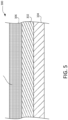
FIG. 5 illustrates a cross-section of the composite textile, in accordance with various embodiments; and -
FIG. 6 illustrates a method of manufacturing an aircraft evacuation slide, in accordance with various embodiments. - The detailed description of exemplary embodiments herein makes reference to the accompanying drawings, which show exemplary embodiments by way of illustration. While these exemplary embodiments are described in sufficient detail to enable those skilled in the art to practice the disclosures, it should be understood that other embodiments may be realized and that logical changes and adaptations in design and construction may be made in accordance with this disclosure and the teachings herein, that fall within the scope of the invention as defined by the claims. Thus, the detailed description herein is presented for purposes of illustration only and not of limitation.
- The scope of the disclosure is defined by the appended claims rather than by merely the examples described. For example, the steps recited in any of the method or process descriptions may be executed in any order and are not necessarily limited to the order presented. Furthermore, any reference to singular includes plural embodiments, and any reference to more than one component or step may include a singular embodiment or step. Also, any reference to tacked, attached, fixed, coupled, connected or the like may include permanent, removable, temporary, partial, full and/or any other possible attachment option. Additionally, any reference to without contact (or similar phrases) may also include reduced contact or minimal contact. Surface shading lines may be used throughout the figures to denote different parts but not necessarily to denote the same or different materials.
- As used herein, "aft" refers to the direction associated with the tail (e.g., the back end) of an aircraft, or generally, to the direction of exhaust of the gas turbine. As used herein, "forward" refers to the direction associated with the nose (e.g., the front end) of an aircraft, or generally, to the direction of flight or motion.
- Polymer coated fabrics may be used in evacuation slide and raft systems. Coated fabrics may be composite structures comprising a woven fabric substrate sandwiched between polyurethane (PU) polymer coatings on either side of the fabric substrate. The coated fabrics may be integrated into inflatable evacuation slides and rafts by various fabrication techniques, such as, for example, adhesive bonding, heat sealing, inductive welding, radio frequency (RF) welding, and the like.
- In various embodiments, the PU coatings may possess air retentive characteristics and radiant heat reflective characteristics. Heat reflective PU coatings may comprise nanofillers disposed in the coatings. Nanofillers may improve polymer properties, such as mechanical, barrier, thermal, flame retardancy, and electrical properties. Moreover, nanofillers may enable modification of polymer morphology. It may be advantageous for aircraft evacuation slides and rafts to be comprised of coated fabrics comprising fillers that may improve the thermal radiant heat characteristics of the coating, improve the coating's mechanical properties, and impart flame retardant characteristics. Moreover, it may be advantageous to disperse or mix nanofillers in coatings, which may enable hot air welding and RF welding of coated fabrics. These nanofillers may also be lightweight and reduce reliance on chemicals, adhesives, and solvents to bond the coated fabric. Accordingly, these heat reflective PU coatings may reduce emission of volatile organic compounds (VOCs) to the environment and may reduce days for manufacturing the evacuations slides and rafts.
- Referring to
FIG. 1 , anexemplary aircraft 100 is shown, in accordance with various embodiments.Aircraft 100 may comprise afuselage 102 withwings 104 fixed tofuselage 102.Emergency exit door 106 may be disposed on fuselage overwing 104 such that passengers exitingemergency exit door 106 would exit ontowing 104. Anevacuation slide assembly 108 may be disposed aft ofemergency exit door 106.Blowout panel 110 may coverevacuation slide assembly 108 when installed on theaircraft 100. In various embodiments, theevacuation slide assembly 108 may include and/or be housed within a packboard mounted to theaircraft 100. Theevacuation slide assembly 108 may jettison theblowout panel 110 and deploy an evacuation slide 200 (FIG. 2 ), such as an inflatable slide, in response toemergency exit door 106 opening or in response to another evacuation event. -
FIG. 2 illustrates an aircraftevacuation slide assembly 200 in accordance with various embodiments. In various embodiments, theassembly 200 may comprise an inertgas inflation system 202 and anevacuation slide 204. The inertgas inflation system 202 may enable inflation of theevacuation slide 204 in the event of an emergency. - In various embodiments, the
evacuation slide 204 assembly may be comprised of a plurality of composite textiles. As shown inFIG. 3 , in various embodiments, eachcomposite textile 300 may comprise afabric substrate 302. In various embodiments, thefabric substrate 302 may be comprised of nylon, polybutylene terephthalate (PBT), polyethylene naphthalate, and the like. - In various embodiments, the
composite textile 300 may comprise an inner polyurethane (PU)coating 304. A PU coating may be a layer applied to the surface of a substrate and may be configured to protect the substrate. For example, a PU coating may protect a substrate from defects such as corrosion, weathering, abrasion, and like deterioration. In various embodiments, a PU coating may be substantially waterproof, preventing water from penetrating a fabric substrate. For aircraft evacuation slides and rafts, it may be advantageous for the slide or raft to comprise an air retentive PU coating. In various embodiments, a PU coating, in a single or multi-layer, may prevent air held in an enclosed space from dissipating through the fabric and into the atmosphere. For evacuation slides and rafts, theinner PU coating 304 may be configured for an inner surface of the slide (204,FIG. 2 ) or raft. - In various embodiments, the
composite textile 300 may further comprise an outer heatreflective coating 306. In various embodiments, the outer heatreflective coating 306 may comprise nanofillers mixed into the coating. Nanofillers may be mixed into the coating when the coating is in its soluble stage. Nanofillers may be additives in solid form. In various embodiments, nanofillers may differ from the polymer matrices to which they may be added in terms of their composition and structure. In various embodiments, nanofillers may be configured to improve the mechanical and physical properties of a polymer. Nanofillers may be one-dimensional, having one dimension less than 100 nanometers (nm). One-dimensional nanofillers may be formed in sheets of 1 to 2 nm thickness. One-dimensional nanofillers may be useful in electrical and thermal applications due to their singular dimensionality. - Nanofillers may be two-dimensional, having two dimensions less than 100 nm. Two-dimensional nanofillers may be shaped as tubes, fibers, or filaments. Two-dimensional nanofillers may impart strong flame-retardant properties to a polymer. Nanofillers may be three-dimensional, having spherical, cubical, or crystalline configurations. Many three-dimensional nanofillers may be useful in coatings applications due to their transparency in visible light.
- As shown in
FIG. 3 , in various embodiments, the outer heatreflective coating 306 may compriseceramic nanoparticles 308.Ceramic nanoparticles 308 may possess beneficial thermal properties such as elevated heat capacity and thermal conductivity. For example, aluminum nitride may exhibit a thermal conductivity of 160 watts per meter Kelvin (W/mK), whereas the thermoplastic polyurethane may exhibit a thermal conductivity of 0.2 (W/mK). Moreover,ceramic nanoparticles 308 may store, dissipate, and/or effuse a radiant heat flux applied to thefabric substrate 302 during, for example, heat sealing or radio frequency (RF) welding. For example, aluminum nitride may exhibit a thermal effusivity of 19.65 (Ws1/2/m2K) × 103, whereas the thermoplastic polyurethane may exhibit a thermal effusivity of 0.60 (Ws1/2/m2K) × 103. - Moreover,
ceramic nanoparticles 308 may be electrically insulating due to their dielectric properties. For example,ceramic nanoparticles 308 may comprise a high dielectric constant and low dissipation factor, which may prevent arcing. The addition ofceramic nanoparticles 308 may be advantageous in that a small number ofceramic nanoparticles 308 may suffice to impart the requisite thermal properties to support hot air welding and RF welding of the polyurethane coatedfabric substrate 302. For example, the addition of nanofillers, such as theceramic nanoparticles 308, may enable joining a plurality of composite textiles to one another using hot air welding and/or RF welding techniques to form an evacuation slide. Additionally,ceramic nanoparticles 308 dispersed within the outer heatreflective coating 306 may possess a high surface area, enabling effective resistance to a radiant heat flux.Ceramic nanoparticles 308 may be, for example, aluminum nitride (AIN), silicon nitride (Si3N4), boron nitride (BN), Alumina, and/or combinations thereof. - Referring to
FIG. 4 , thecomposite textile 300 is shown in accordance with various embodiments. In various embodiments, the heatreflective coating 306 may comprisecarbon allotropes 408.Carbon allotropes 408 may be, for example, carbon nanotubes (CNTs). CNTs may have a cylindrical nanostructure wherein carbons are hybridized with neighboring atoms resembling a graphitic structure. In various embodiments, the heatreflective coating 306 may comprise graphite flakes. In various embodiments, the heatreflective coating 306 may comprise graphene nanosheets. - In various embodiments, dispersing a small amount of
carbon allotropes 408 in the outer heatreflective coating 306 may improve radiant heat characteristics of thecoating 306.Carbon allotropes 408 may comprise high thermal conductivity and electrical conductivity. For example, graphene may exhibit a thermal conductivity of 4000 (W/mK), whereas the thermoplastic polyurethane may exhibit a thermal conductivity of 0.2 (W/mK). Thecarbon allotropes 408 may comprise a high dielectric constant. In various embodiments, thecarbon allotropes 408 may enable a molecular structure to break the movement of free electrons in the outer heatreflective coating 306. The addition ofcarbon allotropes 408 may be advantageous in that a small amount ofcarbon allotropes 408 may suffice to impart the requisite thermal properties to support hot air welding and RF welding of the polyurethane coatedfabric 302. Specifically, a high polymer content ratio may aid in bonding or joining the radiant heat reflective coatedfabric 302 using hot air welding and RF welding techniques. Moreover,carbon allotropes 408 mixed into the outer heatreflective coating 306 may possess a high surface area, enabling effective resistance to a radiant heat flux. - Referring to
FIG. 5 , thecomposite textile 300 is shown in accordance with various embodiments. In various embodiments, the outer heatreflective coating 306 may comprise nano metal particles 508. The nano metal particles 508 may be mixed into the heatreflective coating 306 to improve the radiant heat characteristics of thecoated fabric substrate 302. In various embodiments, the nano metal particles 508 may comprise a high thermal and electrical conductivity. For example, aluminum may exhibit a thermal conductivity of 190 (W/mK), whereas the thermoplastic polyurethane may exhibit a thermal conductivity of 0.2 (W/mK). - Moreover, the nano metal particles 508 may be modified to act as a high dielectric in the heat
reflective coating 306 to break the movement of free electrons in the heatreflective coating 306. The addition of nano metal particles 508 may be advantageous in that a small amount of nano metal particles 508 may suffice to impart the requisite thermal properties to support hot air welding and RF welding of the polyurethane coatedfabric 302. Specifically, a high polymer content ratio may aid in bonding the radiant heat reflective coatedfabric 302 using hot air welding and RF welding techniques. Moreover, nano metal particles 508 dispersed within the outer heatreflective coating 306 may possess a high surface area, enabling effective resistance to a radiant heat flux. Nano metal particles 508 may be, for example, nano-sized aluminum, copper, silver, tungsten, and/or combinations thereof. The nano metal particles 508 may be mixed into the outer heatreflective coating 306 such that the nano metal particles are evenly distributed throughout the outer heatreflective coating 306. - Referring to
FIG. 6 , a method of manufacturing (step 600) an aircraft evacuation slide is shown. The method (step 600) may comprise assembling (step 601) a plurality of composite textiles. The assembling (step 601) of each composite textile may further comprise forming (step 602) an outer heat reflective coating. In various embodiments, the forming (step 602) may further comprise mixing (step 604) a nanofiller compound in a polyurethane coating. In various embodiments, the assembling (step 601) may comprise applying (step 606) the outer heat reflective coating to a first surface of a fabric substrate. In various embodiments, the assembling (step 601) may comprise applying (step 608) an inner polyurethane coating to a second surface of the fabric substrate. In various embodiments, the assembling (step 601) may comprise bonding (step 610) the outer heat reflective coating and the inner polyurethane coating to the fabric substrate. In various embodiments, the method (step 600) may further comprise joining (step 611) the plurality of composite textiles to one another, wherein the joining may be configured to form the aircraft evacuation slide. - In various embodiments, the applying (step 606) the outer heat reflective coating may further comprise coating (step 613) the fabric substrate with the outer heat reflective coating. In various embodiments, the applying (step 608) the inner polyurethane coating may further comprise coating (step 615) the fabric substrate with the inner polyurethane coating. Both the outer heat reflective coating and the inner polyurethane coating may be applied to the fabric substrate by any other suitable application methods, such as, for example, brushing or spraying. In various embodiments, the joining (step 611) may further comprise radio frequency welding (step 612) each composite textile of the plurality of composite textiles to one another. In various embodiments, the joining (step 611) may further comprise hot air welding (step 614) each composite textile of the plurality of composite textiles to one another.
- Benefits, other advantages, and solutions to problems have been described herein with regard to specific embodiments. Furthermore, the connecting lines shown in the various figures contained herein are intended to represent exemplary functional relationships and/or physical couplings between the various elements. It should be noted that many alternative or additional functional relationships or physical connections may be present in a practical system. However, the benefits, advantages, solutions to problems, and any elements that may cause any benefit, advantage, or solution to occur or become more pronounced are not to be construed as critical, required, or essential features or elements of the disclosures.
- The scope of the disclosure is accordingly to be limited by nothing other than the appended claims and their legal equivalents, in which reference to an element in the singular is not intended to mean "one and only one" unless explicitly so stated, but rather "one or more." Moreover, where a phrase similar to "at least one of A, B, or C" is used in the claims, it is intended that the phrase be interpreted to mean that A alone may be present in an embodiment, B alone may be present in an embodiment, C alone may be present in an embodiment, or that any combination of the elements A, B and C may be present in a single embodiment; for example, A and B, A and C, B and C, or A and B and C.
- Systems, methods, and apparatus are provided herein. In the detailed description herein, references to "various embodiments", "one embodiment", "an embodiment", "an example embodiment", etc., indicate that the embodiment described may include a particular feature, structure, or characteristic, but every embodiment may not necessarily include the particular feature, structure, or characteristic. Moreover, such phrases are not necessarily referring to the same embodiment. Further, when a particular feature, structure, or characteristic is described in connection with an embodiment, it is submitted that it is within the knowledge of one skilled in the art to affect such feature, structure, or characteristic in connection with other embodiments whether or not explicitly described. After reading the description, it will be apparent to one skilled in the relevant art(s) how to implement the disclosure in alternative embodiments.
Claims (13)
- A composite textile, comprising:a fabric substrate (302);an inner polyurethane coating (304); andan outer heat reflective coating (306), wherein the outer heat reflective coating comprises nanofillers, wherein the nanofillers are configured to be mixed into the outer heat reflective coating.
- The composite textile of claim 1, wherein the outer heat reflective coating comprises ceramic nanoparticles.
- The composite textile of claim 1, wherein the outer heat reflective coating comprises carbon allotropes.
- The composite textile of claim 3, wherein the outer heat reflective coating comprises graphite flakes.
- The composite textile of claim 4, wherein the outer heat reflective coating comprises graphene nanosheets.
- The composite textile of any preceding claim, wherein the heat reflective coating is configured to be bonded to the fabric substrate.
- The composite textile of claim 1, wherein the heat reflective coating comprises nano metal particles.
- The composite textile of any preceding claim, wherein the fabric substrate is comprised of nylon.
- An aircraft evacuation slide assembly, comprising:an inert gas inflation system (202);
andan evacuation slide (204), wherein the evacuation slide is comprised of a plurality of composite textiles (300), wherein each composite textile of the plurality of composite textiles is configured to be joined to one another, wherein each composite textile is a composite textile as claimed in any preceding claim. - A method of manufacturing an aircraft evacuation slide, comprising:assembling a plurality of composite textiles, wherein the assembling of each composite textile further comprises:forming an outer heat reflective coating, wherein the forming further comprises mixing a nanofiller compound in a polyurethane coating;applying the outer heat reflective coating to a first surface of a fabric substrate;applying an inner polyurethane coating to a second surface of the fabric substrate; andbonding the outer heat reflective coating and the inner polyurethane coating to the fabric substrate; andjoining the plurality of composite textiles to one another, wherein the joining is configured to form the aircraft evacuation slide.
- The method of claim 10, wherein the applying the outer heat reflective coating further comprises coating the fabric substrate with the outer heat reflective coating, wherein the applying the inner polyurethane coating further comprises coating the fabric substrate with the inner polyurethane coating.
- The method of claim 10 or 11, wherein the joining further comprises radio frequency welding each composite textile of the plurality of composite textiles to one another.
- The method of claim 10 or 11, wherein the joining further comprises hot air welding each composite textile of the plurality of composite textiles to one another.
Applications Claiming Priority (2)
| Application Number | Priority Date | Filing Date | Title |
|---|---|---|---|
| IN202241019966 | 2022-04-01 | ||
| US17/856,563 US12122523B2 (en) | 2022-04-01 | 2022-07-01 | Systems and methods for radiant heat reflective aircraft evacuation systems |
Publications (1)
| Publication Number | Publication Date |
|---|---|
| EP4253646A1 true EP4253646A1 (en) | 2023-10-04 |
Family
ID=85792026
Family Applications (1)
| Application Number | Title | Priority Date | Filing Date |
|---|---|---|---|
| EP23165625.7A Pending EP4253646A1 (en) | 2022-04-01 | 2023-03-30 | Systems and methods for radiant heat reflective aircraft evacuation systems |
Country Status (1)
| Country | Link |
|---|---|
| EP (1) | EP4253646A1 (en) |
Citations (3)
| Publication number | Priority date | Publication date | Assignee | Title |
|---|---|---|---|---|
| US20140134355A1 (en) * | 2011-06-08 | 2014-05-15 | Goodrich Corporation | Treated graphene nanoplatelets for inflatable structure barrier layers |
| EP3094484B1 (en) * | 2014-01-17 | 2018-06-27 | Goodrich Corporation | Barrier layer for inflatable structures |
| EP3121329B1 (en) * | 2015-07-20 | 2018-11-21 | Goodrich Corporation | Gas barrier fabric |
-
2023
- 2023-03-30 EP EP23165625.7A patent/EP4253646A1/en active Pending
Patent Citations (3)
| Publication number | Priority date | Publication date | Assignee | Title |
|---|---|---|---|---|
| US20140134355A1 (en) * | 2011-06-08 | 2014-05-15 | Goodrich Corporation | Treated graphene nanoplatelets for inflatable structure barrier layers |
| EP3094484B1 (en) * | 2014-01-17 | 2018-06-27 | Goodrich Corporation | Barrier layer for inflatable structures |
| EP3121329B1 (en) * | 2015-07-20 | 2018-11-21 | Goodrich Corporation | Gas barrier fabric |
Similar Documents
| Publication | Publication Date | Title |
|---|---|---|
| JP5730753B2 (en) | Improved composite materials | |
| US8357740B2 (en) | Co-curable, conductive surfacing films for lightning strike and electromagnetic interference shielding of thermoset composite materials | |
| US8962130B2 (en) | Low density lightning strike protection for use in airplanes | |
| JP6339148B2 (en) | Improved composite materials | |
| JP5080295B2 (en) | Heat dissipating mounting board and manufacturing method thereof | |
| CA2893646C (en) | Conductive surfacing material for composite structures | |
| US11702224B2 (en) | Lightning strike protection | |
| KR20130091496A (en) | Carbon fiber prepreg and manufacturing method thereof | |
| US12122523B2 (en) | Systems and methods for radiant heat reflective aircraft evacuation systems | |
| US11873382B2 (en) | 3D printable polymeric lightning strike protection system for fiber reinforced composites | |
| TW202235401A (en) | Method for producing composite substrate, and composite substrate |
Legal Events
| Date | Code | Title | Description |
|---|---|---|---|
| PUAI | Public reference made under article 153(3) epc to a published international application that has entered the european phase |
Free format text: ORIGINAL CODE: 0009012 |
|
| STAA | Information on the status of an ep patent application or granted ep patent |
Free format text: STATUS: THE APPLICATION HAS BEEN PUBLISHED |
|
| AK | Designated contracting states |
Kind code of ref document: A1 Designated state(s): AL AT BE BG CH CY CZ DE DK EE ES FI FR GB GR HR HU IE IS IT LI LT LU LV MC ME MK MT NL NO PL PT RO RS SE SI SK SM TR |
|
| STAA | Information on the status of an ep patent application or granted ep patent |
Free format text: STATUS: REQUEST FOR EXAMINATION WAS MADE |
|
| 17P | Request for examination filed |
Effective date: 20240403 |
|
| RBV | Designated contracting states (corrected) |
Designated state(s): AL AT BE BG CH CY CZ DE DK EE ES FI FR GB GR HR HU IE IS IT LI LT LU LV MC ME MK MT NL NO PL PT RO RS SE SI SK SM TR |