EP4253634A1 - Clothing treatment device - Google Patents
Clothing treatment device Download PDFInfo
- Publication number
- EP4253634A1 EP4253634A1 EP21899839.1A EP21899839A EP4253634A1 EP 4253634 A1 EP4253634 A1 EP 4253634A1 EP 21899839 A EP21899839 A EP 21899839A EP 4253634 A1 EP4253634 A1 EP 4253634A1
- Authority
- EP
- European Patent Office
- Prior art keywords
- housing
- door cover
- opening
- guide member
- housing opening
- Prior art date
- Legal status (The legal status is an assumption and is not a legal conclusion. Google has not performed a legal analysis and makes no representation as to the accuracy of the status listed.)
- Granted
Links
Images


Classifications
-
- D—TEXTILES; PAPER
- D06—TREATMENT OF TEXTILES OR THE LIKE; LAUNDERING; FLEXIBLE MATERIALS NOT OTHERWISE PROVIDED FOR
- D06F—LAUNDERING, DRYING, IRONING, PRESSING OR FOLDING TEXTILE ARTICLES
- D06F37/00—Details specific to washing machines covered by groups D06F21/00 - D06F25/00
- D06F37/26—Casings; Tubs
- D06F37/28—Doors; Security means therefor
-
- D—TEXTILES; PAPER
- D06—TREATMENT OF TEXTILES OR THE LIKE; LAUNDERING; FLEXIBLE MATERIALS NOT OTHERWISE PROVIDED FOR
- D06F—LAUNDERING, DRYING, IRONING, PRESSING OR FOLDING TEXTILE ARTICLES
- D06F39/00—Details of washing machines not specific to a single type of machines covered by groups D06F9/00 - D06F27/00
-
- D—TEXTILES; PAPER
- D06—TREATMENT OF TEXTILES OR THE LIKE; LAUNDERING; FLEXIBLE MATERIALS NOT OTHERWISE PROVIDED FOR
- D06F—LAUNDERING, DRYING, IRONING, PRESSING OR FOLDING TEXTILE ARTICLES
- D06F29/00—Combinations of a washing machine with other separate apparatus in a common frame or the like, e.g. with rinsing apparatus
-
- D—TEXTILES; PAPER
- D06—TREATMENT OF TEXTILES OR THE LIKE; LAUNDERING; FLEXIBLE MATERIALS NOT OTHERWISE PROVIDED FOR
- D06F—LAUNDERING, DRYING, IRONING, PRESSING OR FOLDING TEXTILE ARTICLES
- D06F39/00—Details of washing machines not specific to a single type of machines covered by groups D06F9/00 - D06F27/00
- D06F39/12—Casings; Tubs
- D06F39/14—Doors or covers; Securing means therefor
-
- D—TEXTILES; PAPER
- D06—TREATMENT OF TEXTILES OR THE LIKE; LAUNDERING; FLEXIBLE MATERIALS NOT OTHERWISE PROVIDED FOR
- D06F—LAUNDERING, DRYING, IRONING, PRESSING OR FOLDING TEXTILE ARTICLES
- D06F23/00—Washing machines with receptacles, e.g. perforated, having a rotary movement, e.g. oscillatory movement, the receptacle serving both for washing and for centrifugally separating water from the laundry
- D06F23/04—Washing machines with receptacles, e.g. perforated, having a rotary movement, e.g. oscillatory movement, the receptacle serving both for washing and for centrifugally separating water from the laundry and rotating or oscillating about a vertical axis
-
- D—TEXTILES; PAPER
- D06—TREATMENT OF TEXTILES OR THE LIKE; LAUNDERING; FLEXIBLE MATERIALS NOT OTHERWISE PROVIDED FOR
- D06F—LAUNDERING, DRYING, IRONING, PRESSING OR FOLDING TEXTILE ARTICLES
- D06F29/00—Combinations of a washing machine with other separate apparatus in a common frame or the like, e.g. with rinsing apparatus
- D06F29/005—Combinations of a washing machine with other separate apparatus in a common frame or the like, e.g. with rinsing apparatus the other separate apparatus being a drying appliance
-
- D—TEXTILES; PAPER
- D06—TREATMENT OF TEXTILES OR THE LIKE; LAUNDERING; FLEXIBLE MATERIALS NOT OTHERWISE PROVIDED FOR
- D06F—LAUNDERING, DRYING, IRONING, PRESSING OR FOLDING TEXTILE ARTICLES
- D06F31/00—Washing installations comprising an assembly of several washing machines or washing units, e.g. continuous flow assemblies
-
- D—TEXTILES; PAPER
- D06—TREATMENT OF TEXTILES OR THE LIKE; LAUNDERING; FLEXIBLE MATERIALS NOT OTHERWISE PROVIDED FOR
- D06F—LAUNDERING, DRYING, IRONING, PRESSING OR FOLDING TEXTILE ARTICLES
- D06F39/00—Details of washing machines not specific to a single type of machines covered by groups D06F9/00 - D06F27/00
- D06F39/12—Casings; Tubs
Definitions
- the present invention relates to the field of laundry treatment, and in particular, a laundry treatment apparatus.
- a washing tub of a laundry treatment apparatus is located in a drawer and is pulled out from a housing along with the drawer. If the door of the washing tub is accidentally opened during washing, a door of the washing tub is blocked by an upper edge of the housing in pulling directly the drawer. So the drawer may not be smoothly pulled out. If an excessive force is applied, the door of the washing tub may be damaged, and it is repaired by extensive disassembly of the device.
- Cida Patent Application No. 201610512207.6 discloses a laundry treatment apparatus, which includes a housing, provided with an opening; a drawer being pulled out from the housing through the opening; a through hole being penetrated through an upper surface of the drawer; a washing tub disposed inside the drawer and providing a space for storing water, and a feeding opening is penetrated through an upper surface of the washing tub and located below the through hole.
- a drum is rotatably disposed inside the washing tub and used for accommodating the laundry supplied by the feeding opening.
- a door is disposed on the drawer or the washing tub and used for opening and closing the feeding opening.
- a guide member is used for preventing the door from being interfered with by the opening when the drawer is pulled out from the housing.
- the guide member may be formed by at least one roller rotatably arranged inside the housing.
- a distance H2 between the upper surface of the drawer and the lowermost end of the roller is preferably shorter than a distance H1 between the upper surface of the drawer and the opening.
- the drawer is smoothly pulled out by the arrangement of the roller in the inside of the housing.
- a part of the opened door cover outside the stroke of the roller is still scratched when the door panel is opened at a very large angle. If the stroke of the roller is large enough, the manufacturing cost is greatly increased.
- a guide member is disposed between an upper edge of a housing opening and a side wall of a housing opposite to the housing opening. If the door cover of a washing tub in a drawer is accidentally opened, the door cover can be moved out of the housing opening along the guide member. So, the drawer can be pulled out of the housing without damaging the door cover of the washing tub.
- the present invention is to provide a laundry treatment apparatus, including:
- the laundry treatment apparatus further includes a guide member, wherein, the guide member is disposed above the door panel, extending from an upper edge of the housing opening towards a side wall of the housing opposite to the housing opening, and used for guiding the door cover of the washing tub to be moved out from the housing opening.
- the guide member is disposed between the upper edge of the housing opening and the side wall of the housing opposite to the housing opening. If the door cover inside the housing is accidentally opened, the door cover can be guided to move out from the housing opening by the guide member. So, the drawer may be smoothly pulled out of the housing without damaging the door cover or leaving scratches on the door cover, thereby achieving a good guiding effect and low manufacturing cost.
- the guide member has a slope inclined relative to the door cover, and is extended obliquely upward from the upper edge of the housing opening towards the side wall of the housing opposite to the housing opening.
- the guide member is used for taking a force for pressing downward when the door cover in an opened state is moved out from the housing.
- the guide member includes an inclined partition plate extending obliquely upward from the upper edge of the housing opening towards the side wall of the housing opposite to the housing opening.
- a first folding edge and a second folding edge which are extended upward are disposed at two ends of the inclined partition plate separately.
- the first folding edge and the second folding edge are correspondingly connected with a side wall of the housing provided with the housing opening and the side wall of the housing opposite to the housing opening separately.
- a stiffener is disposed on the side wall above the housing opening, and the first folding edge of the guide member is mounted on the stiffener.
- the stiffener is provided with a protrusion.
- the first folding edge is provided with a groove matched with the protrusion.
- the guide member is mounted on the protrusion through the groove.
- an included angle ⁇ between the slope and the door cover is in a range of 0° ⁇ ⁇ ⁇ 45°.
- the included angle ⁇ between the slope and the door cover is in a range of 3° ⁇ ⁇ 15°.
- the laundry treatment apparatus further includes an auxiliary guide member that is disposed on a front end of the door cover and is configured to move out from the housing opening along the guide member.
- a front edge of the door cover has an end surface being extended downward.
- the auxiliary guide member is disposed at the junction of the front edge and the end surface of the door cover, and has a circular arc surface protruding from an upper surface and the end surface of the door cover.
- the front edge of the door cover is provided with a groove
- the auxiliary guide member includes a roller rotatably mounted in the groove.
- the front edge of the door cover has an end surface being extended downward.
- the groove is formed in the junction of the upper surface and the end surface of the door cover.
- the roller is configured to protrude from the upper surface and the end surface of the door cover.
- the laundry treatment apparatus has the following beneficial effects compared with the prior art.
- the guide member is disposed between the upper edge of the housing opening and the side wall of the housing opposite to the housing opening. If the door cover inside the housing is accidentally opened, the door cover can be guided to move out from the housing opening by the guide member. So, the drawer can be smoothly pulled out from the housing without damaging the door cover or leaving scratches on the door cover, thereby achieving a good guiding effect and low manufacturing cost.
- 1 housing; 11, housing opening; 2, drawer; 21, drawer opening; 3, washing tub; 31, tub opening; 4, door cover; 41, groove; 42, end surface; 5, auxiliary guide member; 51, roller; 52, rolling shaft; 6, guide member; 61, inclined partition plate; 62, first folding edge; 621, plug-in groove; 63, second folding edge; 7, stiffener; 71, plug-in tongue; 8, washing tub cover.
- connection can be a fixed connection, a detachable connection or an integral connection; can be mechanical connection or electrical connection; and can be direct connection or can be indirect connection through an intermediate.
- connection can be a fixed connection, a detachable connection or an integral connection; can be mechanical connection or electrical connection; and can be direct connection or can be indirect connection through an intermediate.
- a laundry treatment apparatus of the present invention includes a housing 1, a drawer 2, a washing tub 3, and a door cover 4.
- a housing opening 11 is formed in one side of the housing 1.
- the drawer 2 is configured to be inserted into or pulled out from the housing 1 through the housing opening 11.
- a drawer opening 21 is formed in an upper side of the drawer 2.
- the washing tub 3 is located inside the drawer opening 21 and used for storing washing water.
- a tub opening 31 is formed in an upper side of the washing tub 3.
- the front edge of door cover 4 is capable of being open or close, and the door cover 4 is disposed in a pivotal rotation manner and is used for opening or closing the tub opening 31.
- the laundry treatment apparatus further includes a guide member 6 that is disposed above the door cover 4.
- the guide member 6 is extended from an upper edge of the housing opening 11 towards a side wall of the housing 1 opposite to the housing opening 11, and is used for guiding the door cover 4 of the washing tub 3 in the drawer 2 to be moved out from the housing opening 11.
- the guide member 6 is disposed between the upper edge of the housing opening 11 and the side wall of the housing 1 opposite to the housing opening 11.
- the door cover 4 can be guided to move out from the housing opening 11 by the guide member 6 when the door cover 4 inside the housing 1 is accidentally opened, such that the drawer 2 can be smoothly pulled out of the housing 1 without damaging the door cover or leaving scratches on the door cover. Thereby it is achieved a good guiding effect and low manufacturing cost.
- the laundry treatment apparatus of the present invention is a drawer type washing machine.
- the laundry treatment apparatus may be a single drawer type washing machine, or may also be a combined washing machine formed by combination of a drawer type washing machine and other types of washing machines.
- a drum washing machine is located on an upper side
- a drawer type washing machine is located on a lower side.
- a drum type laundry dryer is located on an upper side
- a drawer type washing machine is located on a lower side.
- the guide member 6 has a plane corresponding to the door cover 4.
- the guide member 6 is disposed from the side wall of the housing 1 opposite to the housing opening 11 towards the upper edge of the housing opening 11, and is capable of guiding the door cover 4 to the housing opening 11 along the plane to pull the drawer 2 out of the housing 1.
- the guide member 6 has a slope; and the slope is inclined relative to the door cover 4, and is extended obliquely upward from the upper edge of the housing opening 11 towards the side wall of the housing 1 opposite to the housing opening 11.
- the guide member 6 is used for providing an acting force for pressing downward and guiding the door cover 4 to be moved out of the housing opening 11.
- the guide member 6 has a slope, the slope is inclined relative to the door cover 4, and is extended obliquely upward from the upper edge of the housing opening 11 towards the side wall of the housing 1 opposite to the housing opening 11.
- the guide member 6 is used for providing an acting force for pressing downward and guiding the door cover 4 to be moved out of the housing opening 11.
- the guide member 6 is extended obliquely upward from the upper edge of the housing opening 11 towards the side wall of the housing 1 opposite to the housing opening 11.
- the door cover 4 inside the housing 1 If the door cover 4 inside the housing 1 is accidentally opened, the door cover 4 moves toward the side having the housing opening 11 and abuts with the slope of the guide member 6 when the drawer 2 needs to be pulled out from the housing 1.
- the door cover 4 is gradually closed under the downward force acted by the slope during continuing being pulled to move to the housing opening 11 along the slope. Finally the door cover 4 is pulled out of the housing opening 11, and the drawer 2 is smoothly pulled out of the housing 1.
- One end of the guide member 6 is flush with and attached to the upper edge of the housing opening 11.
- the door cover 4 is guided to move into the housing opening 11, and then moves out of the housing 1 by the guiding member 6. Or, the guide member abuts with the upper edge of the housing opening 11. The door cover 4 is guided to move out of the housing 1 directly along the guide member 6.
- the laundry treatment apparatus further includes a washing tub cover 8 formed on an upper surface of the washing tub 3.
- the washing tub cover 8 includes a feeding opening for communicating the washing tub 3 with the outside of washing tub 3.
- the door cover 4 is mounted on the feeding opening and used for opening/closing the feeding opening.
- the door cover 4 is hinged to the washing tub cover 8, and the front edge of the door panel 4 is rotatable around a hinge axis.
- the guide member 6 includes an inclined partition plate 61 that is extended obliquely upward from the upper edge of the housing opening 11 to the side wall of the housing 1 opposite to the housing opening 11.
- a lower surface of the inclined partition plate 61 is the slope.
- a first folding edge 62 extending upward is disposed at one end of the inclined partition plate 61.
- the first folding edge 62 is connected to the side wall of the housing 1 provided with the housing opening 11.
- a second folding edge 63 extending upward is disposed at the other end of the inclined partition plate 61.
- the second folding edge 63 is connected to the side wall of the housing 1 opposite to the side wall of the housing 1 provided with the housing opening 11.
- the first folding edge 62 is attached to the side wall of the housing 1 provided with the housing opening 11
- the second folding edge 63 is attached to the side wall of the housing 1 opposite to the side wall of the housing 1 provided with the housing opening 11.
- the guide member 6 is a metal or plastic piece.
- the inclined partition plate 61 is a rectangular plate.
- the first folding edge 62 and the second folding edge 63 is arranged at two ends of the inclined partition plate 61 separately, the first folding edge 62 is connected with the side wall of the housing 1 above the housing opening 11, the second folding edge 63 is connected with the side wall of the housing 1 opposite to the side wall of the housing 1 provided with the housing opening 11, thereby the mounting strength of the guide member 6 on the housing 1 is improved and the guide member 6 is prevented from falling.
- first folding edge 62 and the second folding edge 63 are screwed or bolted to the housing 1.
- the inclined partition plate 61 smoothly transitions with the upper edge of the housing opening 11.
- the first folding edge 62 is disposed at one end of the inclined partition plate 61.
- the one end of the inclined partition plate 61 is attached to the upper edge of the housing opening 11, and the slope of the lower surface of the inclined partition plate 61 is flush with the upper edge of the housing opening 11.
- the one end of the inclined partition plate 61 is extended into the housing opening 11 and attached to the upper edge of the inside of the housing opening 11.
- a stiffener 7 is disposed on the side wall of the housing 1 above the housing opening 11, and the first folding edge 62 of the guide member 6 is mounted on the stiffener 7.
- the supporting strength at the position above the housing opening 11 is improved to ensure the mounting stability of the guide member 6, by arranging the stiffener 7 on the side wall of the housing 1 above the housing opening 11 and mounting the first folding edge 62 of the guide member 6 on the stiffener 7.
- the stiffener 7 is also be arranged on the side wall of the housing 1 opposite to the side wall of the housing 1 provided with the housing opening 11, and the second folding edge 63 is mounted on the stiffener 7.
- the stiffener 7 is attached to the side wall of the housing 1.
- the stiffener 7 is a reinforcing plate with rectangular shape, and reinforcing ribs are disposed on the stiffener 7 for increasing the strength of the stiffener 7.
- the stiffener 7 is a metal piece.
- the stiffener 7 is provided with a protrusion 71
- the first folding edge 62 is provided with a groove 621 matched with the protrusion 71.
- the guide member 6 is mounted on the protrusion 71 through the groove 621.
- the protrusion 71 is disposed vertically on the stiffener 7, to facilitate to the mount and position the guide member 6.
- the protrusion 71 is arranged on the stiffener 7, the groove 621 matched with the protrusion 71 is arranged on the first folding edge 62, and the groove 621 of the guide member 6 is mounted on the protrusion 71, so that the support strength for mounting the guide member 6 is improved and the guide member 6 is also positioned and mounted.
- an included angle ⁇ between the slope and the door cover 4 is in a range of 0° ⁇ ⁇ ⁇ 45°.
- the included angle ⁇ is an included angle between the slope and the door cover 4 in a closed state of the door cover 4.
- the smaller included angle ⁇ saves more space within the housing 1 of the laundry treatment apparatus. The door cannot be open the door due to the included angle ⁇ greater than 45°.
- the included angle ⁇ between the slope and the door panel 4 is in a range of 3° ⁇ ⁇ ⁇ 15°. More preferably, the included angle is 3°, 5°, 8°, 10° or 15°.
- the laundry treatment apparatus further includes an auxiliary guide member 5 disposed on a front end of the door cover 4. The front end of the door cover 4 is opposite to the side wall having the housing opening 11. The auxiliary guide member 5 is moved out of the housing opening 11 along the guide member 6, which makes the drawer 2 move out of the housing 1 more smoothly. The guide member 6 is disposed correspondingly to the auxiliary guide member 5.
- the auxiliary guide member 5 moves toward the side having the housing opening 11 and abuts with the slope of the guide member 6 when the drawer 2 needs to be pulled out from the housing 1.
- the door cover 4 is gradually closed under the downward force acted by the slope during continuing moving to the housing opening 11 along the slope. Finally the door cover 4 is pulled out of the housing opening 11, and the drawer 2 is smoothly pulled out of the housing 1.
- the front edge of the door panel 4 has an end surface 42 extending downward.
- the auxiliary guide member 5 is disposed at the junction of the front edge and the end surface 42 of the door cover 4, and has a circular arc surface protruding from the upper surface and the end surface 42 of the door cover 4.
- the circular arc surface is capable of moving along the guide member 6 to prevent the front edge of the door cover from being scratched with the guide member. So, the speed of the door cover moving outward is increased, and the drawer is pulled out of the housing more smoothly.
- the front edge of the door cover 4 is provided with a groove 41.
- the auxiliary guide member 5 includes a roller 51 that is rotatably mounted in the groove 41.
- the front edge of the door cover 4 is relative to the side of the housing 1 provided with the housing opening 11.
- the guide member 6 is disposed above the housing opening 11 and is not be disposed on the upper edge of the housing opening 11.
- the front edge of the door cover 4 is opened upward due to accidental opening of the door cover 4 when the drawer 2 is located in the housing 1.
- the drawer 2 moves forward to drive the front edge of the door cover 4 to move forward.
- the roller 51 on the front edge of the door cover 4 abuts with the guide member 6, such that the door cover 4 is guided by the guide member 6 to move out of the housing 1.
- the groove 41 is formed in the front edge of the door cover 4.
- the auxiliary guide member 5 further includes a rolling shaft 52 through which the roller 51 is mounted in the groove 41.
- a rotation direction of the roller 51 is the same as an opening and closing direction of the door cover 4. The roller 51 rolls along the guide member 6.
- the front edge of the door cover 4 is provided with a groove 41, and the roller 51 is confined in the groove 41 and is configured to freely rotate in the groove 41.
- the front edge of the door cover 4 has an end surface 42 extending downward.
- the groove 41 is formed in the junction of the upper surface and the end surface 42 of the door cover 4.
- the roller 51 protrudes from the upper surface and the end surface 42 of the door cover 4. The roller 51 easily comes into contact with the guide member 6 by the arrangement of the roller 51 protruding from the upper surface and the end surface 42 of the door cover 4, and further the door cover 4 is guided to move out of the housing 1 by the guide member 6.
- the door panel 4 is provided with two sets of auxiliary guide members 5 matched with the guide member 6.
- a width of the inclined partition plate 61 is greater than a distance between the two sets of auxiliary guide members 5, such that the two sets of auxiliary guide members 5 can be in contact with the inclined partition plate 61 and move toward the housing opening 11 along the inclined partition plate 61.
Landscapes
- Engineering & Computer Science (AREA)
- Textile Engineering (AREA)
- Main Body Construction Of Washing Machines And Laundry Dryers (AREA)
- Detail Structures Of Washing Machines And Dryers (AREA)
Abstract
Description
- The present invention relates to the field of laundry treatment, and in particular, a laundry treatment apparatus.
- In the prior art, a washing tub of a laundry treatment apparatus is located in a drawer and is pulled out from a housing along with the drawer. If the door of the washing tub is accidentally opened during washing, a door of the washing tub is blocked by an upper edge of the housing in pulling directly the drawer. So the drawer may not be smoothly pulled out. If an excessive force is applied, the door of the washing tub may be damaged, and it is repaired by extensive disassembly of the device.
-
Chinese Patent Application No. 201610512207.6 - In view of this, the present invention is provided.
- The problem to be solved by the present invention is to overcome the shortcomings of the prior art, and a laundry treatment apparatus is provided. A guide member is disposed between an upper edge of a housing opening and a side wall of a housing opposite to the housing opening. If the door cover of a washing tub in a drawer is accidentally opened, the door cover can be moved out of the housing opening along the guide member. So, the drawer can be pulled out of the housing without damaging the door cover of the washing tub.
- In order to solve the above-mentioned problems, the present invention is to provide a laundry treatment apparatus, including:
- a housing, provided with a housing opening in one side wall;
- a drawer, being capable to be inserted into or pulled out of the housing through the housing opening, and provided with a drawer opening in an upper side;
- a washing tub, located inside the drawer opening, used for storing washing water, and provided with a tub opening in an upper side, and
- a door cover, disposed in a pivotal rotation manner, and used for opening or closing the tub opening.
- The laundry treatment apparatus further includes a guide member, wherein,
the guide member is disposed above the door panel, extending from an upper edge of the housing opening towards a side wall of the housing opposite to the housing opening, and used for guiding the door cover of the washing tub to be moved out from the housing opening. - According to the drawer type laundry treatment apparatus of the present invention, the guide member is disposed between the upper edge of the housing opening and the side wall of the housing opposite to the housing opening. If the door cover inside the housing is accidentally opened, the door cover can be guided to move out from the housing opening by the guide member. So, the drawer may be smoothly pulled out of the housing without damaging the door cover or leaving scratches on the door cover, thereby achieving a good guiding effect and low manufacturing cost.
- Further, the guide member has a slope inclined relative to the door cover, and is extended obliquely upward from the upper edge of the housing opening towards the side wall of the housing opposite to the housing opening. The guide member is used for taking a force for pressing downward when the door cover in an opened state is moved out from the housing.
- Preferably, there is a smooth transition between the slope of the guide member and the upper edge of the housing opening.
- Further, the guide member includes an inclined partition plate extending obliquely upward from the upper edge of the housing opening towards the side wall of the housing opposite to the housing opening.
- A first folding edge and a second folding edge which are extended upward are disposed at two ends of the inclined partition plate separately. The first folding edge and the second folding edge are correspondingly connected with a side wall of the housing provided with the housing opening and the side wall of the housing opposite to the housing opening separately.
- Further, a stiffener is disposed on the side wall above the housing opening, and the first folding edge of the guide member is mounted on the stiffener.
- Further, the stiffener is provided with a protrusion. The first folding edge is provided with a groove matched with the protrusion. The guide member is mounted on the protrusion through the groove.
- Further, an included angle α between the slope and the door cover is in a range of 0° < α < 45°.
- Preferably, the included angle α between the slope and the door cover is in a range of 3° ≤ α≤ 15°.
- Further, the laundry treatment apparatus further includes an auxiliary guide member that is disposed on a front end of the door cover and is configured to move out from the housing opening along the guide member.
- Further, a front edge of the door cover has an end surface being extended downward. The auxiliary guide member is disposed at the junction of the front edge and the end surface of the door cover, and has a circular arc surface protruding from an upper surface and the end surface of the door cover.
- Further, the front edge of the door cover is provided with a groove, and the auxiliary guide member includes a roller rotatably mounted in the groove.
- Further, the front edge of the door cover has an end surface being extended downward. The groove is formed in the junction of the upper surface and the end surface of the door cover. The roller is configured to protrude from the upper surface and the end surface of the door cover.
- By the above technical solutions, the laundry treatment apparatus has the following beneficial effects compared with the prior art.
- According to the drawer type laundry treatment apparatus of the present invention, the guide member is disposed between the upper edge of the housing opening and the side wall of the housing opposite to the housing opening. If the door cover inside the housing is accidentally opened, the door cover can be guided to move out from the housing opening by the guide member. So, the drawer can be smoothly pulled out from the housing without damaging the door cover or leaving scratches on the door cover, thereby achieving a good guiding effect and low manufacturing cost.
- Specific embodiments of the present invention are further described in detail below with reference to the drawings.
- The drawings serve as a part of the present invention to further understand the present invention, and illustrative embodiments of the present invention and the description thereof are used to explain the present invention, but do not constitute an undue limitation on the present invention. Apparently, the drawings in the following description are merely some embodiments, and those of ordinary skill in the art can obtain other drawings according to these drawings without creative work. In the drawings:
-
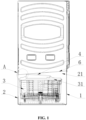
FIG. 1 is a schematic diagram of a laundry treatment apparatus of the present invention; -
FIG. 2 is an enlarged view of a part A inFIG. 1 of the present invention; -
FIG. 3 is another schematic diagram ofFIG. 2 of the present invention; -
FIG. 4 is a schematic diagram of a door cover of the present invention; and -
FIG. 5 is an enlarged top view of a position B inFIG. 4 of the present invention. - In the
figures: 1 , housing; 11, housing opening; 2, drawer; 21, drawer opening; 3, washing tub; 31, tub opening; 4, door cover; 41, groove; 42, end surface; 5, auxiliary guide member; 51, roller; 52, rolling shaft; 6, guide member; 61, inclined partition plate; 62, first folding edge; 621, plug-in groove; 63, second folding edge; 7, stiffener; 71, plug-in tongue; 8, washing tub cover. - It is to be noted that these drawings and description are not intended to limit the scope of concept of the present invention, but are intended to illustrate the concept of the present invention for those skilled in the art with reference to specific embodiments.
- In order to make objects, technical solutions and advantages of the embodiments of the present invention clearer, the solutions in the embodiments are clearly and completely described as follows in combination with accompanying drawings in the embodiments of the present invention. The following embodiments are used for illustrating the present invention, rather than limiting the scope of the present invention.
- In the description of the present invention, it should be noted that, the orientation or positional relationship indicated by such terms as "up", "down", "front", "rear", "left", "right", "vertical", "inner" and "outer" is the orientation or positional relationship based on the accompanying drawings. Such terms are merely used for conveniently and simplified describing the present invention, rather than indicating or implying that the device or element referred to must be located in a certain orientation or must be constructed or operated in a certain orientation. Therefore, the terms cannot be understood as a limitation to the present invention.
- In the description of the present invention, it should be noted that, unless otherwise stipulated and defined definitely, such terms as "installed", "connected" and "in connection" should be understood in their broad sense, e.g., the connection can be a fixed connection, a detachable connection or an integral connection; can be mechanical connection or electrical connection; and can be direct connection or can be indirect connection through an intermediate. For those skilled in the art, specific meanings of the above terms in the present invention can be understood according to specific conditions.
- As shown in
FIGS. 1 to 5 , a laundry treatment apparatus of the present invention includes ahousing 1, adrawer 2, awashing tub 3, and adoor cover 4. - A
housing opening 11 is formed in one side of thehousing 1. Thedrawer 2 is configured to be inserted into or pulled out from thehousing 1 through thehousing opening 11. Adrawer opening 21 is formed in an upper side of thedrawer 2. Thewashing tub 3 is located inside thedrawer opening 21 and used for storing washing water. Atub opening 31 is formed in an upper side of thewashing tub 3. The front edge ofdoor cover 4 is capable of being open or close, and thedoor cover 4 is disposed in a pivotal rotation manner and is used for opening or closing thetub opening 31. - The laundry treatment apparatus further includes a
guide member 6 that is disposed above thedoor cover 4. Theguide member 6 is extended from an upper edge of thehousing opening 11 towards a side wall of thehousing 1 opposite to thehousing opening 11, and is used for guiding thedoor cover 4 of thewashing tub 3 in thedrawer 2 to be moved out from thehousing opening 11. - According to the drawer type laundry treatment apparatus of the present invention, the
guide member 6 is disposed between the upper edge of thehousing opening 11 and the side wall of thehousing 1 opposite to thehousing opening 11. Thedoor cover 4 can be guided to move out from thehousing opening 11 by theguide member 6 when thedoor cover 4 inside thehousing 1 is accidentally opened, such that thedrawer 2 can be smoothly pulled out of thehousing 1 without damaging the door cover or leaving scratches on the door cover. Thereby it is achieved a good guiding effect and low manufacturing cost. - The laundry treatment apparatus of the present invention is a drawer type washing machine. The laundry treatment apparatus may be a single drawer type washing machine, or may also be a combined washing machine formed by combination of a drawer type washing machine and other types of washing machines. For example, in a combined washing machine, a drum washing machine is located on an upper side, and a drawer type washing machine is located on a lower side. Or in a combined washing machine, a drum type laundry dryer is located on an upper side, and a drawer type washing machine is located on a lower side.
- In a solution, the
guide member 6 has a plane corresponding to thedoor cover 4. Theguide member 6 is disposed from the side wall of thehousing 1 opposite to thehousing opening 11 towards the upper edge of thehousing opening 11, and is capable of guiding thedoor cover 4 to thehousing opening 11 along the plane to pull thedrawer 2 out of thehousing 1. - In another solution, the
guide member 6 has a slope; and the slope is inclined relative to thedoor cover 4, and is extended obliquely upward from the upper edge of thehousing opening 11 towards the side wall of thehousing 1 opposite to thehousing opening 11. When thedoor cover 4 is moved out of thehousing 1 in an opened state, theguide member 6 is used for providing an acting force for pressing downward and guiding thedoor cover 4 to be moved out of thehousing opening 11. - In yet another solution, as shown in
FIGS. 2 to 3 , theguide member 6 has a slope, the slope is inclined relative to thedoor cover 4, and is extended obliquely upward from the upper edge of thehousing opening 11 towards the side wall of thehousing 1 opposite to thehousing opening 11. When thedoor cover 4 is moved out from thehousing 1 in an opened state, theguide member 6 is used for providing an acting force for pressing downward and guiding thedoor cover 4 to be moved out of thehousing opening 11. - Preferably, the
guide member 6 is extended obliquely upward from the upper edge of thehousing opening 11 towards the side wall of thehousing 1 opposite to thehousing opening 11. - If the
door cover 4 inside thehousing 1 is accidentally opened, thedoor cover 4 moves toward the side having thehousing opening 11 and abuts with the slope of theguide member 6 when thedrawer 2 needs to be pulled out from thehousing 1. Thedoor cover 4 is gradually closed under the downward force acted by the slope during continuing being pulled to move to thehousing opening 11 along the slope. Finally thedoor cover 4 is pulled out of thehousing opening 11, and thedrawer 2 is smoothly pulled out of thehousing 1. - There is smooth transition between the slope of the
guide member 6 and the upper edge of thehousing opening 11 to facilitate smooth pulling of thedoor cover 4 from thehousing 1. - One end of the
guide member 6 is flush with and attached to the upper edge of thehousing opening 11. Thedoor cover 4 is guided to move into thehousing opening 11, and then moves out of thehousing 1 by the guidingmember 6. Or, the guide member abuts with the upper edge of thehousing opening 11. Thedoor cover 4 is guided to move out of thehousing 1 directly along theguide member 6. - Preferably, the laundry treatment apparatus further includes a
washing tub cover 8 formed on an upper surface of thewashing tub 3. Thewashing tub cover 8 includes a feeding opening for communicating thewashing tub 3 with the outside ofwashing tub 3. Thedoor cover 4 is mounted on the feeding opening and used for opening/closing the feeding opening. Thedoor cover 4 is hinged to thewashing tub cover 8, and the front edge of thedoor panel 4 is rotatable around a hinge axis. - Particularly, the
guide member 6 includes aninclined partition plate 61 that is extended obliquely upward from the upper edge of thehousing opening 11 to the side wall of thehousing 1 opposite to thehousing opening 11. A lower surface of theinclined partition plate 61 is the slope. Afirst folding edge 62 extending upward is disposed at one end of theinclined partition plate 61. Thefirst folding edge 62 is connected to the side wall of thehousing 1 provided with thehousing opening 11. A second folding edge 63 extending upward is disposed at the other end of theinclined partition plate 61. The second folding edge 63 is connected to the side wall of thehousing 1 opposite to the side wall of thehousing 1 provided with thehousing opening 11. - Preferably, the
first folding edge 62 is attached to the side wall of thehousing 1 provided with thehousing opening 11, and the second folding edge 63 is attached to the side wall of thehousing 1 opposite to the side wall of thehousing 1 provided with thehousing opening 11. - Preferably, the
guide member 6 is a metal or plastic piece. Theinclined partition plate 61 is a rectangular plate. - The
first folding edge 62 and the second folding edge 63 is arranged at two ends of theinclined partition plate 61 separately, thefirst folding edge 62 is connected with the side wall of thehousing 1 above thehousing opening 11, the second folding edge 63 is connected with the side wall of thehousing 1 opposite to the side wall of thehousing 1 provided with thehousing opening 11, thereby the mounting strength of theguide member 6 on thehousing 1 is improved and theguide member 6 is prevented from falling. - Preferably, the
first folding edge 62 and the second folding edge 63 are screwed or bolted to thehousing 1. - Preferably, the
inclined partition plate 61 smoothly transitions with the upper edge of thehousing opening 11. - The
first folding edge 62 is disposed at one end of theinclined partition plate 61. The one end of theinclined partition plate 61 is attached to the upper edge of thehousing opening 11, and the slope of the lower surface of theinclined partition plate 61 is flush with the upper edge of thehousing opening 11. - Alternatively, the one end of the
inclined partition plate 61 is extended into thehousing opening 11 and attached to the upper edge of the inside of thehousing opening 11. - A
stiffener 7 is disposed on the side wall of thehousing 1 above thehousing opening 11, and thefirst folding edge 62 of theguide member 6 is mounted on the stiffener 7.The supporting strength at the position above thehousing opening 11 is improved to ensure the mounting stability of theguide member 6, by arranging thestiffener 7 on the side wall of thehousing 1 above thehousing opening 11 and mounting thefirst folding edge 62 of theguide member 6 on thestiffener 7. - Preferably, the
stiffener 7 is also be arranged on the side wall of thehousing 1 opposite to the side wall of thehousing 1 provided with thehousing opening 11, and the second folding edge 63 is mounted on thestiffener 7. - The
stiffener 7 is attached to the side wall of thehousing 1. Thestiffener 7 is a reinforcing plate with rectangular shape, and reinforcing ribs are disposed on thestiffener 7 for increasing the strength of thestiffener 7. Thestiffener 7 is a metal piece. - Further, the
stiffener 7 is provided with aprotrusion 71, and thefirst folding edge 62 is provided with agroove 621 matched with theprotrusion 71. Theguide member 6 is mounted on theprotrusion 71 through thegroove 621. Theprotrusion 71 is disposed vertically on thestiffener 7, to facilitate to the mount and position theguide member 6. - The
protrusion 71 is arranged on thestiffener 7, thegroove 621 matched with theprotrusion 71 is arranged on thefirst folding edge 62, and thegroove 621 of theguide member 6 is mounted on theprotrusion 71, so that the support strength for mounting theguide member 6 is improved and theguide member 6 is also positioned and mounted. - Further, an included angle α between the slope and the
door cover 4 is in a range of 0° < α < 45°. The included angle α is an included angle between the slope and thedoor cover 4 in a closed state of thedoor cover 4. The smaller included angle α saves more space within thehousing 1 of the laundry treatment apparatus. The door cannot be open the door due to the included angle α greater than 45°. - In a preferable solution, the included angle α between the slope and the
door panel 4 is in a range of 3° ≤ α ≤ 15°. More preferably, the included angle is 3°, 5°, 8°, 10° or 15°.The laundry treatment apparatus further includes anauxiliary guide member 5 disposed on a front end of thedoor cover 4. The front end of thedoor cover 4 is opposite to the side wall having thehousing opening 11. Theauxiliary guide member 5 is moved out of thehousing opening 11 along theguide member 6, which makes thedrawer 2 move out of thehousing 1 more smoothly. Theguide member 6 is disposed correspondingly to theauxiliary guide member 5. - If the
door cover 4 inside thehousing 1 is accidentally opened, theauxiliary guide member 5 moves toward the side having thehousing opening 11 and abuts with the slope of theguide member 6 when thedrawer 2 needs to be pulled out from thehousing 1. Thedoor cover 4 is gradually closed under the downward force acted by the slope during continuing moving to thehousing opening 11 along the slope. Finally thedoor cover 4 is pulled out of thehousing opening 11, and thedrawer 2 is smoothly pulled out of thehousing 1. - In a solution, as shown in
FIG. 2 , the front edge of thedoor panel 4 has anend surface 42 extending downward. Theauxiliary guide member 5 is disposed at the junction of the front edge and theend surface 42 of thedoor cover 4, and has a circular arc surface protruding from the upper surface and theend surface 42 of thedoor cover 4. The circular arc surface is capable of moving along theguide member 6 to prevent the front edge of the door cover from being scratched with the guide member. So, the speed of the door cover moving outward is increased, and the drawer is pulled out of the housing more smoothly. - In another solution, as shown in
FIG. 3 , the front edge of thedoor cover 4 is provided with agroove 41. Theauxiliary guide member 5 includes aroller 51 that is rotatably mounted in thegroove 41. The front edge of thedoor cover 4 is relative to the side of thehousing 1 provided with thehousing opening 11. In this solution, theguide member 6 is disposed above thehousing opening 11 and is not be disposed on the upper edge of thehousing opening 11. - The front edge of the
door cover 4 is opened upward due to accidental opening of thedoor cover 4 when thedrawer 2 is located in thehousing 1. When thedrawer 2 is pulled, thedrawer 2 moves forward to drive the front edge of thedoor cover 4 to move forward. Theroller 51 on the front edge of thedoor cover 4 abuts with theguide member 6, such that thedoor cover 4 is guided by theguide member 6 to move out of thehousing 1. - As shown in
FIGS. 4 to 5 , thegroove 41 is formed in the front edge of thedoor cover 4. Theauxiliary guide member 5 further includes a rollingshaft 52 through which theroller 51 is mounted in thegroove 41. A rotation direction of theroller 51 is the same as an opening and closing direction of thedoor cover 4. Theroller 51 rolls along theguide member 6. - Alternatively, the front edge of the
door cover 4 is provided with agroove 41, and theroller 51 is confined in thegroove 41 and is configured to freely rotate in thegroove 41. - The front edge of the
door cover 4 has anend surface 42 extending downward. Thegroove 41 is formed in the junction of the upper surface and theend surface 42 of thedoor cover 4. Theroller 51 protrudes from the upper surface and theend surface 42 of thedoor cover 4. Theroller 51 easily comes into contact with theguide member 6 by the arrangement of theroller 51 protruding from the upper surface and theend surface 42 of thedoor cover 4, and further thedoor cover 4 is guided to move out of thehousing 1 by theguide member 6. - Preferably, the
door panel 4 is provided with two sets ofauxiliary guide members 5 matched with theguide member 6. - A width of the
inclined partition plate 61 is greater than a distance between the two sets ofauxiliary guide members 5, such that the two sets ofauxiliary guide members 5 can be in contact with theinclined partition plate 61 and move toward thehousing opening 11 along theinclined partition plate 61. - The embodiments merely describe preferred embodiments of the present invention, rather than limiting the concept and scope of the present invention. The preferred embodiments are disclosed above, and not used for limiting the present invention. Under the premise of not departing from the idea of the present invention, various changes and improvements made to the technical solution of the present invention by those skilled in the art, such as simple amendment, equal change and modify according concept of the present invention, shall all fall within the protection scope of the present invention. The solutions in the above embodiments can be further combined or substituted.
Claims (10)
- A laundry treatment apparatus, including:a housing, provided with a housing opening in one side wall;a drawer, being capable to be inserted into or pulled out of the housing through the housing opening, and provided with a drawer opening in an upper side;a washing tub, located inside the drawer opening, used for storing washing water, and provided with a tub opening in an upper side.a door cover, disposed in a pivotal rotation manner, and used for opening or closing the tub opening, wherein,a guide member is provided,the guide member is disposed above the door cover, extended from an upper edge of the housing opening towards a side wall of the housing opposite to the housing opening, and used for guiding the door cover of the washing tub to be moved out from the housing opening.
- The laundry treatment apparatus according to claim 1, wherein, the guide member has a slope inclined relative to the door cover, and is extended obliquely upward from the upper edge of the housing opening towards the side wall of the housing opposite to the housing opening, and is used for taking a force for pressing downward on the door cover during moving out of the housing in an opened state.
preferably, there is a smooth transition between the slope of the guide member and the upper edge of the housing opening. - The laundry treatment apparatus according to claim 2, wherein, the guide member includes an inclined partition plate extending obliquely upward from the upper edge of the housing opening towards the side wall of the housing opposite to the housing opening,
a first folding edge and a second folding edge extending upward are disposed at two ends of the inclined partition plate separately, and the first folding edge and the second folding edge are correspondingly connected with the side wall of the housing provided with the housing opening and the side wall of the housing opposite to the housing opening separately. - The laundry treatment apparatus according to claim 3, wherein, a stiffener is disposed on the side wall above the housing opening, and the first folding edge of the guide member is mounted on the stiffener.
- The laundry treatment apparatus according to claim 4, wherein, the stiffener is provided with a protrusion, the first folding edge is provided with a groove matched with the protrusion, and the guide member is mounted on the protrusion through the groove.
- The laundry treatment apparatus according to any one of claims 2-5, wherein, an included angle α between the slope and the door cover is in a range of 0° < α < 45°.
preferably, the included angle α between the slope and the door cover is in a range of 3° ≤ α≤ 15°. - The laundry treatment apparatus according to any one of claims 1-6, further including an auxiliary guide member that is disposed on a front end of the door cover and is configured to move out from the housing opening along the guide member.
- The laundry treatment apparatus according to claim 7, wherein, a front edge of the door cover has an end surface being extended downward,
the auxiliary guide member is disposed at a junction of the front edge and the end surface of the door cover, and has a circular arc surface protruding from an upper surface and the end surface of the door cover. - The laundry treatment apparatus according to claim 7, wherein, the front edge of the door cover is provided with a groove, and the auxiliary guide member includes a roller rotatably mounted in the groove.
- The laundry treatment apparatus according to claim 9, wherein, the front edge of the door cover has an end surface being extended downward, the groove is formed in the junction of the upper surface and the end surface of the door cover, and the roller is configured to protrude from the upper surface and the end surface of the door cover.
Applications Claiming Priority (2)
| Application Number | Priority Date | Filing Date | Title |
|---|---|---|---|
| CN202011407803.0A CN114592325B (en) | 2020-12-03 | 2020-12-03 | Clothes processing device |
| PCT/CN2021/130633 WO2022116805A1 (en) | 2020-12-03 | 2021-11-15 | Clothing treatment device |
Publications (4)
| Publication Number | Publication Date |
|---|---|
| EP4253634A1 true EP4253634A1 (en) | 2023-10-04 |
| EP4253634A4 EP4253634A4 (en) | 2024-05-01 |
| EP4253634C0 EP4253634C0 (en) | 2025-04-02 |
| EP4253634B1 EP4253634B1 (en) | 2025-04-02 |
Family
ID=81812077
Family Applications (1)
| Application Number | Title | Priority Date | Filing Date |
|---|---|---|---|
| EP21899839.1A Active EP4253634B1 (en) | 2020-12-03 | 2021-11-15 | Clothing treatment device |
Country Status (3)
| Country | Link |
|---|---|
| EP (1) | EP4253634B1 (en) |
| CN (1) | CN114592325B (en) |
| WO (1) | WO2022116805A1 (en) |
Family Cites Families (19)
| Publication number | Priority date | Publication date | Assignee | Title |
|---|---|---|---|---|
| NZ335414A (en) * | 1997-01-30 | 2000-10-27 | Fisher & Paykel | Dishwasher chamber having drain pump impeller with upper disc sealing against casing, and lower blade roots radially spaced from hub to allow air accumulation for priming |
| KR100400448B1 (en) * | 2000-12-15 | 2003-10-01 | 엘지전자 주식회사 | A door apparatus of the drawer type washing machine |
| KR100601436B1 (en) * | 2004-07-09 | 2006-07-14 | 주식회사 대우일렉트로닉스 | Lead lifting device for dish washer |
| KR101290466B1 (en) * | 2006-12-14 | 2013-07-26 | 엘지전자 주식회사 | Drawer assembly and washer including the same |
| US20080159907A1 (en) * | 2006-12-29 | 2008-07-03 | Joshi Anand G | Methods and apparatus for disinfecting and/or deodorizing an article |
| KR101467749B1 (en) * | 2007-05-17 | 2014-12-03 | 엘지전자 주식회사 | Device for treating laundry |
| KR20090052458A (en) * | 2007-11-21 | 2009-05-26 | 엘지전자 주식회사 | Clothing processing device |
| GB2478540A (en) * | 2010-03-09 | 2011-09-14 | Mark Shuttleworth | Device to prevent jamming of drawers and the loss of items behind a rear wall |
| US9388523B2 (en) * | 2011-08-31 | 2016-07-12 | Lg Electronics Inc. | Laundry treating apparatus |
| JP5588948B2 (en) * | 2011-09-29 | 2014-09-10 | 日立アプライアンス株式会社 | Drum washing machine |
| KR102082700B1 (en) * | 2013-01-16 | 2020-02-28 | 엘지전자 주식회사 | The auxiliary washing machine and cloth treating apparatus using the same |
| KR20150025083A (en) * | 2013-08-28 | 2015-03-10 | 엘지전자 주식회사 | Laundry Treating Apparatus |
| KR102255385B1 (en) * | 2014-05-30 | 2021-05-25 | 엘지전자 주식회사 | Laundry Treating Apparatus |
| KR102397005B1 (en) * | 2015-06-30 | 2022-05-11 | 엘지전자 주식회사 | Laundry Treating Apparatus |
| KR102401639B1 (en) * | 2015-06-30 | 2022-05-25 | 엘지전자 주식회사 | Laundry Treating Apparatus |
| KR20170002883A (en) * | 2015-06-30 | 2017-01-09 | 엘지전자 주식회사 | Laundry Treating Apparatus |
| KR102402082B1 (en) * | 2015-06-30 | 2022-05-26 | 엘지전자 주식회사 | Laundry Treating Apparatus |
| KR102423575B1 (en) * | 2018-03-29 | 2022-07-20 | 엘지전자 주식회사 | Washing machine |
| CN210314937U (en) * | 2019-04-12 | 2020-04-14 | 无锡小天鹅电器有限公司 | Washing machine |
-
2020
- 2020-12-03 CN CN202011407803.0A patent/CN114592325B/en active Active
-
2021
- 2021-11-15 EP EP21899839.1A patent/EP4253634B1/en active Active
- 2021-11-15 WO PCT/CN2021/130633 patent/WO2022116805A1/en not_active Ceased
Also Published As
| Publication number | Publication date |
|---|---|
| EP4253634C0 (en) | 2025-04-02 |
| EP4253634A4 (en) | 2024-05-01 |
| EP4253634B1 (en) | 2025-04-02 |
| CN114592325B (en) | 2025-09-26 |
| WO2022116805A1 (en) | 2022-06-09 |
| CN114592325A (en) | 2022-06-07 |
Similar Documents
| Publication | Publication Date | Title |
|---|---|---|
| US8893531B2 (en) | Washing machine | |
| EP3165667A1 (en) | Laundry treating apparatus | |
| US20040144138A1 (en) | Drum-type laundry machine | |
| KR20060036538A (en) | Drum washing machine with folding door | |
| US9556552B2 (en) | Door hinge apparatus and drum type washing machine having the same | |
| EP1262589B1 (en) | Door for electric household-appliance and relative electric household-appliance | |
| EP3168359A1 (en) | Laundry treating apparatus | |
| US5857363A (en) | Cover structure of a clothes washing machine | |
| CN111691151A (en) | Washing machine | |
| EP4253634B1 (en) | Clothing treatment device | |
| CN207420280U (en) | Buckle structure, door system and window system | |
| KR20060035412A (en) | Drum Washing Machine with Up and Down Retractable Door | |
| JP7136698B2 (en) | clothing processing equipment | |
| CN216530021U (en) | Draw-out type switch cabinet structure convenient to overhaul | |
| CN114592326B (en) | Clothes processing device | |
| CN114592327B (en) | Clothes processing device | |
| CN106761084B (en) | A kind of connection hinge for cabinet inside finance device | |
| CN218492024U (en) | Clothes treatment device | |
| KR950000132Y1 (en) | Auxiliary device for opening baffle board of ice machine | |
| CN224063106U (en) | Drum washing machine | |
| KR20170081469A (en) | Laundry Treating Apparatus | |
| CN214376719U (en) | Vending machine cabinet door and vending machine | |
| KR200172799Y1 (en) | Sliding open and close structure of small wicker basket type iron cage | |
| CN223376159U (en) | Drawer, drawer assembly and electrical equipment | |
| CN114753114A (en) | Clothes treatment device |
Legal Events
| Date | Code | Title | Description |
|---|---|---|---|
| STAA | Information on the status of an ep patent application or granted ep patent |
Free format text: STATUS: THE INTERNATIONAL PUBLICATION HAS BEEN MADE |
|
| PUAI | Public reference made under article 153(3) epc to a published international application that has entered the european phase |
Free format text: ORIGINAL CODE: 0009012 |
|
| STAA | Information on the status of an ep patent application or granted ep patent |
Free format text: STATUS: REQUEST FOR EXAMINATION WAS MADE |
|
| 17P | Request for examination filed |
Effective date: 20230629 |
|
| AK | Designated contracting states |
Kind code of ref document: A1 Designated state(s): AL AT BE BG CH CY CZ DE DK EE ES FI FR GB GR HR HU IE IS IT LI LT LU LV MC MK MT NL NO PL PT RO RS SE SI SK SM TR |
|
| DAV | Request for validation of the european patent (deleted) | ||
| DAX | Request for extension of the european patent (deleted) | ||
| REG | Reference to a national code |
Ref country code: DE Ref legal event code: R079 Ipc: D06F0029000000 Ref country code: DE Ref legal event code: R079 Ref document number: 602021028696 Country of ref document: DE Free format text: PREVIOUS MAIN CLASS: D06F0039140000 Ipc: D06F0029000000 |
|
| A4 | Supplementary search report drawn up and despatched |
Effective date: 20240404 |
|
| RIC1 | Information provided on ipc code assigned before grant |
Ipc: D06F 31/00 20060101ALN20240327BHEP Ipc: D06F 39/12 20060101ALN20240327BHEP Ipc: D06F 23/04 20060101ALN20240327BHEP Ipc: D06F 37/28 20060101ALI20240327BHEP Ipc: D06F 29/00 20060101AFI20240327BHEP |
|
| GRAP | Despatch of communication of intention to grant a patent |
Free format text: ORIGINAL CODE: EPIDOSNIGR1 |
|
| STAA | Information on the status of an ep patent application or granted ep patent |
Free format text: STATUS: GRANT OF PATENT IS INTENDED |
|
| RIC1 | Information provided on ipc code assigned before grant |
Ipc: D06F 31/00 20060101ALN20241115BHEP Ipc: D06F 39/12 20060101ALN20241115BHEP Ipc: D06F 23/04 20060101ALN20241115BHEP Ipc: D06F 37/28 20060101ALI20241115BHEP Ipc: D06F 29/00 20060101AFI20241115BHEP |
|
| RIC1 | Information provided on ipc code assigned before grant |
Ipc: D06F 31/00 20060101ALN20241129BHEP Ipc: D06F 39/12 20060101ALN20241129BHEP Ipc: D06F 23/04 20060101ALN20241129BHEP Ipc: D06F 37/28 20060101ALI20241129BHEP Ipc: D06F 29/00 20060101AFI20241129BHEP |
|
| INTG | Intention to grant announced |
Effective date: 20241212 |
|
| GRAS | Grant fee paid |
Free format text: ORIGINAL CODE: EPIDOSNIGR3 |
|
| GRAA | (expected) grant |
Free format text: ORIGINAL CODE: 0009210 |
|
| STAA | Information on the status of an ep patent application or granted ep patent |
Free format text: STATUS: THE PATENT HAS BEEN GRANTED |
|
| AK | Designated contracting states |
Kind code of ref document: B1 Designated state(s): AL AT BE BG CH CY CZ DE DK EE ES FI FR GB GR HR HU IE IS IT LI LT LU LV MC MK MT NL NO PL PT RO RS SE SI SK SM TR |
|
| REG | Reference to a national code |
Ref country code: GB Ref legal event code: FG4D |
|
| REG | Reference to a national code |
Ref country code: CH Ref legal event code: EP |
|
| REG | Reference to a national code |
Ref country code: IE Ref legal event code: FG4D |
|
| REG | Reference to a national code |
Ref country code: DE Ref legal event code: R096 Ref document number: 602021028696 Country of ref document: DE |
|
| U01 | Request for unitary effect filed |
Effective date: 20250429 |
|
| U07 | Unitary effect registered |
Designated state(s): AT BE BG DE DK EE FI FR IT LT LU LV MT NL PT RO SE SI Effective date: 20250507 |
|
| PG25 | Lapsed in a contracting state [announced via postgrant information from national office to epo] |
Ref country code: ES Free format text: LAPSE BECAUSE OF FAILURE TO SUBMIT A TRANSLATION OF THE DESCRIPTION OR TO PAY THE FEE WITHIN THE PRESCRIBED TIME-LIMIT Effective date: 20250402 |
|
| PG25 | Lapsed in a contracting state [announced via postgrant information from national office to epo] |
Ref country code: GR Free format text: LAPSE BECAUSE OF FAILURE TO SUBMIT A TRANSLATION OF THE DESCRIPTION OR TO PAY THE FEE WITHIN THE PRESCRIBED TIME-LIMIT Effective date: 20250703 Ref country code: NO Free format text: LAPSE BECAUSE OF FAILURE TO SUBMIT A TRANSLATION OF THE DESCRIPTION OR TO PAY THE FEE WITHIN THE PRESCRIBED TIME-LIMIT Effective date: 20250702 |
|
| PG25 | Lapsed in a contracting state [announced via postgrant information from national office to epo] |
Ref country code: PL Free format text: LAPSE BECAUSE OF FAILURE TO SUBMIT A TRANSLATION OF THE DESCRIPTION OR TO PAY THE FEE WITHIN THE PRESCRIBED TIME-LIMIT Effective date: 20250402 |
|
| PG25 | Lapsed in a contracting state [announced via postgrant information from national office to epo] |
Ref country code: HR Free format text: LAPSE BECAUSE OF FAILURE TO SUBMIT A TRANSLATION OF THE DESCRIPTION OR TO PAY THE FEE WITHIN THE PRESCRIBED TIME-LIMIT Effective date: 20250402 |
|
| PG25 | Lapsed in a contracting state [announced via postgrant information from national office to epo] |
Ref country code: RS Free format text: LAPSE BECAUSE OF FAILURE TO SUBMIT A TRANSLATION OF THE DESCRIPTION OR TO PAY THE FEE WITHIN THE PRESCRIBED TIME-LIMIT Effective date: 20250702 |
|
| PG25 | Lapsed in a contracting state [announced via postgrant information from national office to epo] |
Ref country code: IS Free format text: LAPSE BECAUSE OF FAILURE TO SUBMIT A TRANSLATION OF THE DESCRIPTION OR TO PAY THE FEE WITHIN THE PRESCRIBED TIME-LIMIT Effective date: 20250802 |
|
| U20 | Renewal fee for the european patent with unitary effect paid |
Year of fee payment: 5 Effective date: 20251126 |
|
| PG25 | Lapsed in a contracting state [announced via postgrant information from national office to epo] |
Ref country code: SM Free format text: LAPSE BECAUSE OF FAILURE TO SUBMIT A TRANSLATION OF THE DESCRIPTION OR TO PAY THE FEE WITHIN THE PRESCRIBED TIME-LIMIT Effective date: 20250402 |
|
| PG25 | Lapsed in a contracting state [announced via postgrant information from national office to epo] |
Ref country code: CZ Free format text: LAPSE BECAUSE OF FAILURE TO SUBMIT A TRANSLATION OF THE DESCRIPTION OR TO PAY THE FEE WITHIN THE PRESCRIBED TIME-LIMIT Effective date: 20250402 |
|
| PG25 | Lapsed in a contracting state [announced via postgrant information from national office to epo] |
Ref country code: SK Free format text: LAPSE BECAUSE OF FAILURE TO SUBMIT A TRANSLATION OF THE DESCRIPTION OR TO PAY THE FEE WITHIN THE PRESCRIBED TIME-LIMIT Effective date: 20250402 |
|
| PLBE | No opposition filed within time limit |
Free format text: ORIGINAL CODE: 0009261 |
|
| STAA | Information on the status of an ep patent application or granted ep patent |
Free format text: STATUS: NO OPPOSITION FILED WITHIN TIME LIMIT |
|
| REG | Reference to a national code |
Ref country code: CH Ref legal event code: L10 Free format text: ST27 STATUS EVENT CODE: U-0-0-L10-L00 (AS PROVIDED BY THE NATIONAL OFFICE) Effective date: 20260211 |
|
| 26N | No opposition filed |
Effective date: 20260105 |