EP4253303A1 - Method for generating cargo handling transport path, cargo handling transport crane, and cargo handling transport method - Google Patents
Method for generating cargo handling transport path, cargo handling transport crane, and cargo handling transport method Download PDFInfo
- Publication number
- EP4253303A1 EP4253303A1 EP21897422.8A EP21897422A EP4253303A1 EP 4253303 A1 EP4253303 A1 EP 4253303A1 EP 21897422 A EP21897422 A EP 21897422A EP 4253303 A1 EP4253303 A1 EP 4253303A1
- Authority
- EP
- European Patent Office
- Prior art keywords
- cargo handling
- arm
- cargo
- crane
- transport path
- Prior art date
- Legal status (The legal status is an assumption and is not a legal conclusion. Google has not performed a legal analysis and makes no representation as to the accuracy of the status listed.)
- Pending
Links
Images





Classifications
-
- B—PERFORMING OPERATIONS; TRANSPORTING
- B66—HOISTING; LIFTING; HAULING
- B66C—CRANES; LOAD-ENGAGING ELEMENTS OR DEVICES FOR CRANES, CAPSTANS, WINCHES, OR TACKLES
- B66C13/00—Other constructional features or details
- B66C13/18—Control systems or devices
- B66C13/48—Automatic control of crane drives for producing a single or repeated working cycle; Program control
-
- B—PERFORMING OPERATIONS; TRANSPORTING
- B66—HOISTING; LIFTING; HAULING
- B66C—CRANES; LOAD-ENGAGING ELEMENTS OR DEVICES FOR CRANES, CAPSTANS, WINCHES, OR TACKLES
- B66C13/00—Other constructional features or details
- B66C13/18—Control systems or devices
- B66C13/46—Position indicators for suspended loads or for crane elements
-
- B—PERFORMING OPERATIONS; TRANSPORTING
- B66—HOISTING; LIFTING; HAULING
- B66C—CRANES; LOAD-ENGAGING ELEMENTS OR DEVICES FOR CRANES, CAPSTANS, WINCHES, OR TACKLES
- B66C23/00—Cranes comprising essentially a beam, boom, or triangular structure acting as a cantilever and mounted for translatory of swinging movements in vertical or horizontal planes or a combination of such movements, e.g. jib-cranes, derricks, tower cranes
- B66C23/88—Safety gear
-
- G—PHYSICS
- G06—COMPUTING OR CALCULATING; COUNTING
- G06N—COMPUTING ARRANGEMENTS BASED ON SPECIFIC COMPUTATIONAL MODELS
- G06N3/00—Computing arrangements based on biological models
- G06N3/004—Artificial life, i.e. computing arrangements simulating life
- G06N3/006—Artificial life, i.e. computing arrangements simulating life based on simulated virtual individual or collective life forms, e.g. social simulations or particle swarm optimisation [PSO]
Definitions
- the present invention relates to a method for generating a cargo handling transport path, a cargo handling transport crane, and a cargo handling transport method.
- automating crane operations As a labor saving method for the swinging cargo handling transport crane, automating crane operations is mentioned. To automate crane operations, there is a necessity of automatically calculating a cargo handling transport path from a cargo handling initial position, which is the current position of a suspended cargo, and a cargo handling target position, which is a transport destination of the suspended cargo.
- a method therefor a method has been conventionally taken which includes controlling the swinging of a swinging body and the luffing of a jib of a tower crane (cargo handling transport crane) and transporting the suspended cargo in a straight line track having the shortest distance (PTL 1) .
- the transport distance is the shortest because the suspended cargo is transported in the straight line track.
- the cargo handling transport crane has the minimum swinging radius due to the facility structure. Therefore, when the cargo handling initial position and the cargo handling target position are connected by a straight line path, a non-transportable route is sometimes generated in which the swinging radius of the cargo handling transport crane falls below the lower limit in the facility constraints (i.e., equal to or less than the minimum swinging radius) in the middle of the transfer.
- a non-transportable route is generated in which the swinging radius of the cargo handling transport crane falls below the lower limit in the facility constraints in the middle of the transfer.
- the present invention has been made focusing on the above-described problem. It is an object of the present invention to provide a method for generating a cargo handling transport path which makes it possible to transport the suspended cargo in a short time from the optional cargo handling initial position to the optional cargo handling target position by the cargo handling transport crane, a cargo handling transport crane, and a cargo handling transport method.
- One aspect of the present invention provides a method for generating a cargo handling transport path for generating a cargo handling transport path for transporting a suspended cargo suspended from an arm tip portion of a crane arm from an optional cargo handling initial position to an optional cargo handling target position by swinging movement of the crane arm, and the method includes: calculating the cargo handling transport path and a cargo handling transport velocity for transporting the suspended cargo in a straight line track as viewed from at least the vertical direction in at least a part of the cargo handling transport path based on the cargo handling initial position, the cargo handling target position, the range of the arm minimum swinging circle of the crane arm, the upper limit swinging angular velocity of the crane arm, the upper limit swinging angular acceleration of the crane arm, the upper limit luffing velocity of the crane arm, and the upper limit luffing acceleration of the crane arm.
- One aspect of the present invention provides a cargo handling transport crane including: a crane arm configured to be able to perform swinging movement and have an arm tip portion from which a suspended cargo is suspended; an arm swinging mechanism configured to swing the crane arm; an arm luffing mechanism configured to adjust the luffing angle of the crane arm; and a control device configured to control the arm swinging mechanism and the arm luffing mechanism such that a track of the suspended cargo is a straight line track as viewed from at least the vertical direction in at least a part of a cargo handling transport path, in which the control device generates the cargo handling transport path and a cargo handling transport velocity using the method for generating a cargo handling transport path described in any one of claims 1 to 4, and transports the suspended cargo based on the cargo handling transport path.
- One aspect of the present invention provides a cargo handling transport method including: transporting a suspended cargo using the cargo handling transport crane.
- One aspect of the present invention provides a method for generating a cargo handling transport path which makes it possible to transport a suspended cargo in a short time from an optional cargo handling initial position to an optional cargo handling target position by a cargo handling transport crane, the cargo handling transport crane, and a cargo handling transport method.
- the cargo handling transport crane 1 includes a crane arm 2 capable of performing swinging movement, an arm luffing mechanism 3, an arm swinging mechanism 4, an arm extension mechanism 5, and a wire 6 as illustrated in FIGS. 1 and 2 .
- the tip to which the wire 6 is attached of the crane arm 2 is also referred to as an arm tip portion 21.
- the x-axis, y-axis, and the z-axis are axes orthogonal to each other, the x-axis and the y-axis are axes parallel to the horizontal direction, and the z-axis is an axis parallel to the vertical direction.
- the cargo handling transport crane 1 lifts a suspended cargo 7 attached to the tip of the wire 6 and transports the same from a cargo handling initial position A 1 to a cargo handling target position A 2 .
- the coordinates of the cargo handling initial position A 1 are (x 1 , y 1 ) [unit: m]
- the coordinates of the cargo handling target position A 2 are (x 2 , y 2 ) [unit: m].
- the suspended cargo 7 is a coil that is a product manufactured in steel works as one example.
- the arm luffing mechanism 3 adjusts a luffing angle ⁇ [deg], which is the angle in the extension direction of the crane arm 2 with respect to the horizontal direction.
- the arm swinging mechanism 4 adjusts a swinging angle ⁇ [deg], which is the angle in the extension direction of the crane arm 2 with respect to the x-axis direction, by swinging the crane arm 2.
- the arm extension mechanism 5 adjusts an arm length L [m], which is the projection length in the extension direction of the crane arm 2 from the supporting position of the crane arm 2 provided with the arm swinging mechanism 4.
- the cargo handling transport crane 1 may not include the arm extension mechanism 5.
- the cargo handling transport crane 1 is further provided with a hoisting device (not illustrated) adjusting the wire length from the arm tip portion 21 of the wire 6. Further, the cargo handling transport crane 1 is provided with a control device (not illustrated) controlling the arm luffing mechanism 3, the arm swinging mechanism 4, the arm extension mechanism 5, and the hoisting device and adjusting the luffing angle ⁇ , the swinging angle ⁇ , the arm length L, and the wire length to transport the suspended cargo 7 from the cargo handling initial position A 1 to the cargo handling target position A 2 .
- the control device generates a cargo handling transport path which is a track of the suspended cargo 7 according to the cargo handling initial position, the cargo handling target position, and the swinging radius of the cargo handling transport crane 1.
- the control device arithmetically operates the swinging angle ⁇ , the luffing angle ⁇ , and the arm length L of the crane arm 2 such that the track of the suspended cargo 7 is the generated cargo handling transport path using the generated cargo handling transport path, a maximum velocity v max [m/s] of the arm tip portion 21, a suspended cargo swing cycle T [s], and a rise time T 1 [s].
- the control device controls the arm swinging mechanism 4, the arm luffing mechanism 3, and the arm extension mechanism 5 such that the arithmetically operated swinging angle ⁇ , luffing angle ⁇ , and arm length L are achieved, thereby transporting the suspended cargo 7. Details of a method for stopping the swing of the cargo handling transport crane 1 by the control device are described below.
- a cargo handling range D a in which the suspended cargo 7 can be transported of the cargo handling transport crane 1 is an annular range equal to or larger than a minimum swinging radius r min [m] and within a maximum swinging radius r max [m] around a swinging center C r (point C r ). More specifically, the transport of the suspended cargo 7 by the cargo handling transport crane 1 cannot be performed in a region outside the cargo handling range D a (position where the distance from the swinging center C r is less than the minimum swinging radius r min or larger than the maximum swinging radius r max ).
- the cargo handling transport path of the cargo handling transport crane 1 is considered in a plane view viewed from the vertical direction as illustrated in FIG. 3 .
- the axes parallel to the horizontal plane and orthogonal to each other are defined as the x-axis and the y-axis, and the position through which the suspended cargo 7 passes is expressed by the x-y coordinates.
- the suspended cargo 7 is transported in the cargo handling transport path determined by a method for generating a cargo handling transport path described later using the cargo handling transport crane 1. Further, in addition to the generation of the cargo handling transport path, the maximum velocity of the arm tip portion 21 during steady rest transport is also calculated. The suspended cargo is transported at the cargo handling transport velocity of a velocity pattern in which the steady rest control is performed according to the maximum velocity.
- the velocity pattern of the steady rest control As the velocity pattern of the steady rest control, the velocity pattern described in " Automation of Overhead Traveling Cranes, Okawa et al., NKK Technical Report, edited by Nippon Kokan Techno Service Co., Ltd., 1995, No. 149 " is applicable, for example.
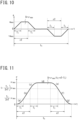
- the velocity v [m/s] of the arm tip portion 21 of the crane arm is controlled with the velocity and acceleration patterns illustrated in FIGS. 4A and 4B , respectively.
- the transport period is divided into 7 sections of (a) to (g) in a linear transport path, and the velocities represented by Expressions (1) to (7) below according to an elapsed time t [s] from the start of the transport are set.
- v max indicates the maximum velocity [m/s]
- t c indicates a transport time [s] of the suspended cargo.
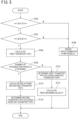
- step S100 it is first determined whether a first distance d 1 [m] between the swinging center C r of the cargo handling transport crane 1 and the cargo handling initial position A 1 is equal to or larger than the minimum swinging radius r min of the cargo handling transport crane 1 and within the maximum swinging radius r max of the cargo handling transport crane 1 (S100). In step S100, it may be determined whether the cargo handling initial position A 1 falls within the cargo handling range D a , instead of the determination described above.
- Step S100 when the first distance d 1 is equal to or larger than the minimum swinging radius r min and within the maximum swinging radius r max , it is determined whether a second distance d 2 [m] between the swinging center C r of the cargo handling transport crane 1 and the cargo handling target position A 2 is equal to or larger than the minimum swinging radius r min of the cargo handling transport crane and within the maximum swinging radius r max of the cargo handling transport crane 1 (S102). In Step S102, it may be determined whether the cargo handling target position A 2 falls within the cargo handling range D a , instead of the determination described above.
- Step S100 when the first distance d 1 is less than the minimum swinging radius r min or larger than the maximum swinging radius r max or when the second distance d 2 is less than the minimum swinging radius r min or larger than the maximum swinging radius r max , an error is issued, and the processing of generating the cargo handling transport path ends (S104).
- Step S104 is processed, a situation occurs in which at least one of the current cargo handling initial position A 1 and cargo handling target position A 2 cannot be accessed from the cargo handling transport crane 1. This makes it impossible to form a cargo handling transport path having the current cargo handling initial position A 1 and cargo handling target position A 2 .
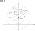
- Step S102 when the second distance d 2 is equal to or larger than the minimum swinging radius r min and within the maximum swinging radius r max , a linear path (straight ling L 0 ) connecting the cargo handling initial position A 1 and the cargo handling target position A 2 is calculated as the first transport path as illustrated in FIG. 6 (S106).
- the first transport path is a straight line track represented by Expression (11) below.
- x and y indicate the x-coordinate and the y-coordinate, respectively, of the arm tip portion 21 of the crane arm 2. [Expression 2]
- y y 2 ⁇ y 1 x 2 ⁇ x 1 x + y 1 ⁇ y 2 ⁇ y 1 x 2 ⁇ x 1 x 1
- Step S106 it is determined whether the number of intersection points between a circle R 1 in which the radius around the swinging center C r is the minimum swinging radius r min and a straight line L 0 is 2 or more (S108).
- the circle R 1 is represented by Expression (12) below.
- the circle R 1 is also referred to as an arm minimum swinging circle of the crane arm 2. More specifically, in Step S108, when the discriminant of Expression (13) (Expression (14)) obtained by substituting Expression (12) into Expression (11) takes a positive value, the number of the intersection points is determined to be 2 or more, otherwise the number of the intersection points is determined to be less than 2.
- the coordinates of the swinging center point C r are (0, y c ).
- Step S108 when the number of the intersection points is determined to be 1 or less, it is determined that the first transport path falls within the cargo handling range of the cargo handling transport crane 1, and the first transport path is adopted as the final cargo handling transport path. (S110). For example, when the cargo handling target positions in FIG. 6 are A 2a , A 2b , the number of the intersection points between the circle R 1 and the straight line L 0 (L 0a , L 0b ) is 1 or less.
- Step S110 a first maximum velocity v max1 [m/s] is calculated, which is the maximum velocity of the arm tip portion 21 during the steady rest transport in a path from the cargo handling initial position A 1 to the cargo handling target position A 2 (S112).
- v max1 the maximum velocity of the arm tip portion 21 during the steady rest transport in a path from the cargo handling initial position A 1 to the cargo handling target position A 2 (S112).
- a relay point A 3 is calculated (S114). For example, when the cargo handling target position in FIG. 6 is A 2c , the number of the intersection points between the circle R 1 and the straight line L 0 (L 0c ) is 2. A method for calculating the relay point A 3 is described later.
- Step S116 a second transport path, which is a transport route passing through the relay point A 3 , is determined as the final cargo handling transport path (S116). Further, in Step S116, the maximum velocities of the arm tip portion 21 during the steady rest transport in the second transport path (second maximum velocity v max2 and third maximum velocity v max3 described later) are calculated as described later.
- the cargo handling transport path and the maximum velocity of the arm tip portion 21 during the steady rest transport are generated.
- the relay point A 3 is a point where the transport time from the cargo handling initial position to the cargo handling target position is the shortest, and is determined as follows.
- a transport time t c from the cargo handling initial position A 1 to the cargo handling target position A 2 is represented by Expression (15) using the coordinates of the points A 1 to A 3 , the second maximum velocity v max2 [m/s], which is the maximum velocity of the arm tip portion 21 during the steady rest transport in a path from the cargo handling initial position A 1 to the relay point A 3 , the third maximum velocity v max3 [m/s], which is the maximum velocity of the arm tip portion 21 during the steady rest transport in a path from the relay point A 3 to the cargo handling target position A 2 , and the swing cycle T [s] of the suspended cargo.
- the swing cycle T is defined by Expression (16) below.
- the second maximum velocity v max3 and the third maximum velocity v max3 are affected by the facility constraints of the crane, such as the swinging angular velocity, the swinging angular acceleration, the luffing velocity, and the luffing acceleration of the crane arm.
- the swinging angular velocity among the above even in the case of the same upper limit value, when the swinging radius in the middle of the path increases, the second maximum velocity v max2 and the third maximum velocity v max3 at the arm tip portion 21 can be proportionally increased, which is advantageous.
- a smaller swinging radius in the middle of the path is advantageous because the path is closer to the shortest path.
- the transport time t c changes in a complicated manner due to the change in the swinging radius in the middle of the path, and thus it is difficult to analytically determine the same. Therefore, as a search problem, the relay point A 3 where a transport time T s is the shortest is derived.
- a particle swarm optimization method is applied, which includes arranging particle swarms and searching for a solution for minimizing an objective function by iterative calculations.
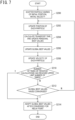
- FIG. 7 illustrates one example of a method for deriving the relay point using the particle swarm optimization method.
- Step S200 a transport time t ci is calculated from the maximum second velocity v max2 and the maximum third velocity v max3 which can be taken for each of the scattered particles, and the values of the position and the transport time are recorded as personal best values (x pi , y bi , t cpi ) for each particle. Further, in Step S200, the position and the transport time of a particle having the shortest transport time among all the particles are recorded as global best values (x g , y g , t cg ).
- Step S202 when the transport time t ci is calculated from the maximum second maximum velocity v max2 and the third maximum velocity v max3 which can be taken for each particle, and then compared with the personal best value t cpi , resulting in t ci ⁇ t cpi , the (x pi , y pi , t cpi ) values are updated with the current value as the personal best values (S204).
- Step S206 when there is t cpi satisfying t cpi ⁇ t cg , the (x g , y g , t cg ) values are updated with the values as the global best values (S206).
- Step S206 when there is no t cpi satisfying t cpi ⁇ t cg , the global best values are not updated and the recorded global best values are maintained.
- a method for deriving the second maximum velocity v max2 and the third maximum velocity v max3 is described later using FIG. 8 .
- Step S206 the velocities (v xi , v yi ) of each particle are updated according to Expressions (19) and (20) below using constants c 1 , c 2 , w (S208).
- Step S208 it is determined whether the number of times of the iterative calculations from Steps S202 to S208 has reached the upper limit number of times (S210).
- the calculations in Steps S202 to S208 are repeatedly performed as described later.
- the upper limit number of times is not particularly limited, but may be set to about 400 times.
- Step S212 it is determined whether the global best values have converged.
- the determination of whether the global best values have converged may be performed by determining that the global best values have converged when the global best values obtained in the calculations in Steps S202 to S208 iteratively performed do not change, for example.
- the determination of whether the global best values have converged may be performed by determining that the global best values have converged when the change amount of the global best values obtained by the iterative calculations is equal to or less than a predetermined threshold, for example.
- Step S212 When the global best values have not converged in the determination in Step S212, the steps in and after Step S202 are performed again.
- the personal best values of each particle obtained in the previous Step S206 are used as the initial position and the initial velocity.
- the second transport path which is a transport path from the cargo handling initial position A 1 to the cargo handling target position A 2 and passes through the relay point A 3 .
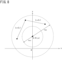
- the second transport path L 1 includes a transport path L 1a from the cargo handling initial position A 1 to the relay point A 3 and a transport path L 1b from the relay point A 3 to the cargo handling target position A 2 as illustrated in FIG. 8 , for example.
- the transport path L 1a and the transport path L 1b each are linear paths as with the first transport path.
- the method for deriving the relay point by the particle swarm optimization method of this embodiment generates the relay point A 3 and the second transport path by iteratively performing the calculation steps from Step S202 to S208 for a specified number of calculation steps or until the global best values have converged.
- a temporary maximum transport velocity v max0 is set for the linear transport path (S300).
- the position where the cargo handling is started is referred to as a start position and the position where the cargo handling ends is referred to as an end position.
- the cargo handling initial position A 1 serves as the start position and the cargo handling target position A 2 serves as the end position.
- the second maximum velocity v max3 is derived, the cargo handling initial position A 1 serves as the start position and the relay point A 3 serves as the end position.
- the relay point A 3 serves as the start position and the cargo handling target position A 2 serves as the end position.
- the maximum values ⁇ max , d ⁇ max , dr max , and d 2 r max of the swinging angular velocity ⁇ 1 , the swinging angular acceleration dw, the luffing velocity dr, and the luffing acceleration d 2 r, respectively, of the crane arm 2 in the transport from the start position to the end position are determined (S302).
- ratios ⁇ 1 , ⁇ 2 , ⁇ 3 , and ⁇ 4 of the maximum values ⁇ max , d ⁇ max , dr max , and d 2 r max and upper values ⁇ lim , d ⁇ lim , dr lim , and d 2 r lim of the swinging angular velocity ⁇ 1 , the swinging angular acceleration dw, the luffing velocity dr, and the luffing acceleration d 2 r are individually calculated using Expressions (21) to (24) below, respectively, (S304). Then, in Step S304, the largest ratio among the ratios ⁇ 1 , ⁇ 2 , ⁇ 3 , and ⁇ 4 is defined as ⁇ max .
- the upper limit values ⁇ lim , d ⁇ lim , dr lim , and d 2 r lim are preset values from the facility specification of the cargo handling transport crane 1.
- Step S308 When it is determined in Step S308 that ⁇ max has not converged to 1, the processing in and after Step S302 is repeated. In the processing in Step S302 on and after the second time, the calculation is performed using the value obtained by dividing the temporary maximum velocity v max0 by ⁇ max in the previous Step S306 as the temporary maximum velocity v max0 . More specifically, in this embodiment, the processing from Steps S302 to S306 is iteratively performed until ⁇ max has converged to 1.
- Step S308 When it is determined in Step S308 that ⁇ max has converged to 1, the used temporary maximum velocity v max0 is set as the maximum velocity v max (S310).
- the maximum velocity v max is derived. More specifically, in this embodiment, the maximum velocity v max is calculated based on the cargo handling initial position A 1 , the cargo handling target position A 2 , the range of the arm minimum swinging circle of the crane arm 2, the upper limit swinging angular velocity ⁇ lim of the crane arm 2, the upper limit swinging angular acceleration d ⁇ lim of the crane arm 2, the upper limit luffing velocity dr lim of the crane arm 2, and the upper limit luffing acceleration d 2 r lim of the crane arm 2.
- the maximum velocity v max is calculated in which the maximum values of the swinging angular velocity ⁇ 1 , the swinging angular acceleration d ⁇ , the luffing velocity dr, and the luffing acceleration d 2 r of the crane arm 2 each are less than the upper limits.
- the maximum velocity that the cargo handling transport crane 1 can take in the cargo handling transport path can be set as the maximum velocity v max during the steady rest transport, and the transport time can be shortened.
- the setting of the relay point A 3 enables the transport of the suspended cargo 7 in a linear cargo handling transport path even when a straight line path connecting the cargo handling initial position A 1 and the cargo handling target position A 2 is set as the cargo handling transport path, and the swinging radius of the cargo handling transport crane falls below the lower limit in the facility constraints in the middle of the path.
- the transport path in which the transport time is the shortest is set as the second transport path. Therefore, the transport time can be shortened as compared with a case where only the shortest path is set as the second transport path.
- the steady rest control of the suspended cargo is performed by the velocity pattern control of the tip of the crane, but the present invention is not limited to such an example.
- Feedback control may be combined with the above-described velocity pattern control when the influence of disturbance due to wind or the like is large.
- the velocity patterns of Expressions (1) to (7) are used, but the present invention is not limited to such an example.
- acceleration patterns and velocity patterns illustrated in FIGS. 10 and 11 may be used.
- an acceleration a is linearly raised at a rise time T 1 [s], which is a constant time.
- the rise time T 1 is a predetermined time during which the acceleration a is changed, and is preferably set as short as possible within the facility specification range.
- the acceleration is performed over a time (nT) that is n (natural number) times as long as the swing cycle T at the constant acceleration a.
- the acceleration a is linearly reduced in the time T 1 , and the transport at a constant speed is performed.
- the swing angle of the suspended cargo becomes 0 during the transport at the constant speed.
- an operation reverse to the operation in the acceleration is performed, and the suspended cargo is stopped at the target position at the swing angle of 0.
- a velocity v of the arm tip portion 21 changes as illustrated in FIG. 11 .
- t t is a transport time [s] of the suspended cargo
- the transport time t t is set such that an area S (integral value of the graph) of a region surrounded by the solid line indicating the velocity and a t-axis of the graph in FIG. 10 represented by Expression (25) below is the distance from the cargo handling initial position to the cargo handling target position.
- the velocity v of the arm tip portion 21 at each elapsed time t is represented by Expressions (26) to (32) below.
- Expression (26) indicates the velocity v of the arm tip portion 21 at a time when t ⁇ T 1 is established
- Expression (27) indicates the same at a time when T 1 ⁇ t ⁇ nT is established
- Expression (28) indicates the same at a time when nT ⁇ t ⁇ nT+T 1 is established
- Expression (29) indicates the same at a time when nT+T 1 ⁇ t ⁇ t t -nT-T 1 is established
- Expression (30) indicates a time when t t -nT-T 1 ⁇ t ⁇ t t -nT is established
- Expression (31) indicates the same at a time when t t -nT ⁇ t ⁇ t t -T 1 is established
- Expression (32) indicates the same at an elapsed time when t t -T 1 ⁇ t ⁇ t t is established.
- the relay point A 3 is set by determining whether the number of the intersection points is 2 or more in the determination in Step S108, but the present invention is not limited to such an example.
- the first transport path is set as the cargo handling transport path, and the suspended cargo 7 may be transported in the velocity pattern according to the first maximum velocity v max .
- the entire cargo handling transport path is the straight line track, but the cargo handling transport path may partially include a part that is not a straight line track but a circular arc track.
- Example 1 the steady rest control was performed in the cargo handling transport crane 1 illustrated in FIGS. 1 and 2 .
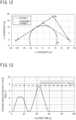
- a 10 t hot-rolled coil suspended by the wire 6 having a length of 10 m was used as the suspended cargo 7, and a path in the case of transporting the suspended cargo from the coordinates (20, 0), which is the handling initial position A 1 , to the coordinates (-20, 0), which is the cargo handling target position A 2 , by a swinging crane having the swinging center at (0, 0) at the coordinates (x, y) [unit: m] was generated.
- the minimum swinging radius of the swinging crane was 11 m and the maximum swinging radius thereof was 45 m.
- the upper limits of the crane arm swinging angular velocity, the crane arm swinging angular acceleration, the crane arm luffing velocity, and the crane arm luffing acceleration of the swinging crane were 7.5 deg/s, 0.65 deg/s 2 , 1.0 m/s, and 0.3 m/s 2 , respectively.
- the transport time at this time was 60.0 seconds.
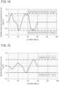
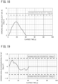
- the values of the crane arm swinging angular velocity, the crane arm swinging angular acceleration, the crane arm luffing velocity, and the crane arm luffing acceleration are illustrated in FIGS. 13 to 16 , respectively. As is clear from FIGS. 13 to 16 , it was able to be confirmed that all the values fall within the upper limits.
- the second maximum velocity v max2 , the third maximum velocity v max3 , and the transport time were derived when a relay point A 3a having the coordinates of (0.0, 13.2) was taken to obtain the shortest route for comparison (Comparative Example 1). Both the second maximum velocity v max3 and the third maximum velocity v max3 decreased to 0.82 m/s to keep the swinging angular velocity and the like within the upper limits. In connection therewith, the transport time also became 77.0 seconds, resulting in an increase in the transport time as compared with Example 1.
- the relay point A 3 and the transport velocity were able to be derived in which the transport time was the shortest within the specification limit of the cargo handling transport crane.
- Example 2 the transport velocity was derived for the first transport path not passing through the relay point A 3 from the cargo handling initial position A 1 at the coordinates (20, 10) to the cargo handling target position A 2 at the coordinates (-20, 20) as illustrated in FIG. 17 in the same cargo handling transport crane 1 as that in Example 1.
- Example 2 the first maximum velocity v max1 of 1.27 m/s was derived.
- the transport time at this time was 41.6 seconds.
- values of the crane arm swinging angular velocity, the crane arm swinging angular acceleration, the crane arm luffing velocity, and the crane arm luffing acceleration in Example 2 are illustrated in FIGS. 18 to 22, respectively. As is clear from FIGS. 18 to 22, all the values fall within the upper limits.
- the transport velocity was able to be derived in which the transport time is the shortest within the specification limit of the cargo handling transport crane 1.
Landscapes
- Engineering & Computer Science (AREA)
- Mechanical Engineering (AREA)
- Automation & Control Theory (AREA)
- Control And Safety Of Cranes (AREA)
Abstract
There are provided a method for generating a cargo handling transport path which makes it possible to transport a suspended cargo in a short time from an optional cargo handling initial position to an optional cargo handling target position by a cargo handling transport crane (1), the cargo handling transport crane (1), and a cargo handling transport method. A method for generating a cargo handling transport path for generating a cargo handling transport path for transporting a suspended cargo (7) suspended from an arm tip portion of a crane arm (2) from an optional cargo handling initial position to an optional cargo handling target position by swinging movement of the crane arm (2), and the method includes: calculating the cargo handling transport path and a cargo handling transport velocity for transporting the suspended cargo in a straight line track as viewed from at least the vertical direction in at least a part of the cargo handling transport path based on the cargo handling initial position, the cargo handling target position, the range of the arm minimum swinging circle of the crane arm (2), the upper limit swinging angular velocity of the crane arm (2), the upper limit swinging angular acceleration of the crane arm (2), the upper limit luffing velocity of the crane arm (2), and the upper limit luffing acceleration of the crane arm (2).
Description
- The present invention relates to a method for generating a cargo handling transport path, a cargo handling transport crane, and a cargo handling transport method.
- For example, when products, such as coils, are shipped from steel works, the transport is performed using a swinging cargo handling transport crane. This work is performed by a land-side worker performing slinging, a crane operator operating the crane, and a shipboard worker aligning and lashing the coils in the ship, so that the work requires manpower. Therefore, considering the future decline in the working population, there is a need for labor saving.
- As a labor saving method for the swinging cargo handling transport crane, automating crane operations is mentioned. To automate crane operations, there is a necessity of automatically calculating a cargo handling transport path from a cargo handling initial position, which is the current position of a suspended cargo, and a cargo handling target position, which is a transport destination of the suspended cargo. As a method therefor, a method has been conventionally taken which includes controlling the swinging of a swinging body and the luffing of a jib of a tower crane (cargo handling transport crane) and transporting the suspended cargo in a straight line track having the shortest distance (PTL 1) .
- PTL 1:
JP 2019-112178 A - In the method described in
PTL 1, there is no description regarding the maximum velocity during the suspended cargo transport. However, the maximum velocity changes depending on the swinging radius in the middle of the path or the like, and therefore it has been difficult to set the maximum velocity according to the cargo handling transport path. - Further, in the method described in
PTL 1, the transport distance is the shortest because the suspended cargo is transported in the straight line track. However, the cargo handling transport crane has the minimum swinging radius due to the facility structure. Therefore, when the cargo handling initial position and the cargo handling target position are connected by a straight line path, a non-transportable route is sometimes generated in which the swinging radius of the cargo handling transport crane falls below the lower limit in the facility constraints (i.e., equal to or less than the minimum swinging radius) in the middle of the transfer. For example, when the cargo handling initial position and the cargo handling target position of the suspended cargo are located at positions almost directly opposite each other across the cargo handling transport crane, for example, a non-transportable route is generated in which the swinging radius of the cargo handling transport crane falls below the lower limit in the facility constraints in the middle of the transfer. - Thus, the present invention has been made focusing on the above-described problem. It is an object of the present invention to provide a method for generating a cargo handling transport path which makes it possible to transport the suspended cargo in a short time from the optional cargo handling initial position to the optional cargo handling target position by the cargo handling transport crane, a cargo handling transport crane, and a cargo handling transport method.
- One aspect of the present invention provides a method for generating a cargo handling transport path for generating a cargo handling transport path for transporting a suspended cargo suspended from an arm tip portion of a crane arm from an optional cargo handling initial position to an optional cargo handling target position by swinging movement of the crane arm, and the method includes: calculating the cargo handling transport path and a cargo handling transport velocity for transporting the suspended cargo in a straight line track as viewed from at least the vertical direction in at least a part of the cargo handling transport path based on the cargo handling initial position, the cargo handling target position, the range of the arm minimum swinging circle of the crane arm, the upper limit swinging angular velocity of the crane arm, the upper limit swinging angular acceleration of the crane arm, the upper limit luffing velocity of the crane arm, and the upper limit luffing acceleration of the crane arm.
- One aspect of the present invention provides a cargo handling transport crane including: a crane arm configured to be able to perform swinging movement and have an arm tip portion from which a suspended cargo is suspended; an arm swinging mechanism configured to swing the crane arm; an arm luffing mechanism configured to adjust the luffing angle of the crane arm; and a control device configured to control the arm swinging mechanism and the arm luffing mechanism such that a track of the suspended cargo is a straight line track as viewed from at least the vertical direction in at least a part of a cargo handling transport path, in which the control device generates the cargo handling transport path and a cargo handling transport velocity using the method for generating a cargo handling transport path described in any one of
claims 1 to 4, and transports the suspended cargo based on the cargo handling transport path. - One aspect of the present invention provides a cargo handling transport method including: transporting a suspended cargo using the cargo handling transport crane.
- One aspect of the present invention provides a method for generating a cargo handling transport path which makes it possible to transport a suspended cargo in a short time from an optional cargo handling initial position to an optional cargo handling target position by a cargo handling transport crane, the cargo handling transport crane, and a cargo handling transport method.
-
-
FIG. 1 is a side view illustrating a cargo handling transport crane according to one embodiment of the present invention; -
FIG. 2 is a plane view illustrating the cargo handling transport crane according to one embodiment of the present invention; -
FIG. 3 is an explanatory view illustrating the cargo handling range of the cargo handling transport crane; -
FIG. 4A and 4B are graphs illustrating an acceleration pattern and a velocity pattern, respectively, of steady rest control, in whichFIG. 4A illustrates the acceleration velocity pattern andFIG. 4B illustrates the velocity pattern; -
FIG. 5 is a flow chart illustrating a method for generating a cargo handling transport path according to one embodiment of the present invention; -
FIG. 6 is an explanatory view illustrating the relationship between a first transport path and an arm minimum swinging circle; -
FIG. 7 is a flow chart illustrating a method for generating a relay point and a second transport path; -
FIG. 8 is an explanatory view illustrating one example of the second transport path; -
FIG. 9 is a flow chart illustrating a method for calculating the maximum velocity; -
FIG. 10 is a graph illustrating a modification of the acceleration pattern of the steady rest control; -
FIG. 11 is a graph illustrating a modification of the velocity pattern of the steady rest control; -
FIG. 12 is an explanatory view illustrating a cargo handling transport path in Example 1; -
FIG. 13 is a graph illustrating the swinging angular velocity result in Example 1; -
FIG. 14 is a graph illustrating the swinging angular acceleration result in Example 1; -
FIG. 15 is a graph illustrating the retracting velocity result in Example 1; -
FIG. 16 is a graph illustrating the retracting acceleration result in Example 1; -
FIG. 17 is an explanatory view illustrating a cargo handling transport path in Example 2; -
FIG. 18 is a graph illustrating the swinging angular velocity result in Example 2; -
FIG. 19 is a graph illustrating the swinging angular acceleration result in Example 2; -
FIG. 20 is a graph illustrating the retracting velocity result in Example 2; and -
FIG. 21 is a graph illustrating the retracting acceleration result in Example 2. - A detailed description below describes an embodiment of the present invention with reference to the drawings. In the description of the drawings, the same or similar reference numerals are attached to the same or similar parts, and duplicated descriptions are omitted. The drawings are schematic and are sometimes different from the actual ones. The embodiment described below exemplifies devices and methods for embodying the technical idea of the present invention. The technical idea of the present invention does not specify materials, structures, arrangement, and the like of constituent components to the materials, structures, arrangement, and the like described below. The technical idea of the present invention can be variously altered within the technical range defined by Claims.
- A cargo
handling transport crane 1 according to one embodiment of the present invention is described. The cargohandling transport crane 1 includes acrane arm 2 capable of performing swinging movement, anarm luffing mechanism 3, anarm swinging mechanism 4, anarm extension mechanism 5, and awire 6 as illustrated inFIGS. 1 and 2 . The tip to which thewire 6 is attached of thecrane arm 2 is also referred to as anarm tip portion 21. In the drawings, the x-axis, y-axis, and the z-axis are axes orthogonal to each other, the x-axis and the y-axis are axes parallel to the horizontal direction, and the z-axis is an axis parallel to the vertical direction. The cargohandling transport crane 1 lifts a suspended cargo 7 attached to the tip of thewire 6 and transports the same from a cargo handling initial position A1 to a cargo handling target position A2. As illustrated inFIG. 3 , the coordinates of the cargo handling initial position A1 are (x1, y1) [unit: m], and the coordinates of the cargo handling target position A2 are (x2, y2) [unit: m]. In this embodiment, the suspended cargo 7 is a coil that is a product manufactured in steel works as one example. - The
arm luffing mechanism 3 adjusts a luffing angle ϕ [deg], which is the angle in the extension direction of thecrane arm 2 with respect to the horizontal direction. Thearm swinging mechanism 4 adjusts a swinging angle θ [deg], which is the angle in the extension direction of thecrane arm 2 with respect to the x-axis direction, by swinging thecrane arm 2. Thearm extension mechanism 5 adjusts an arm length L [m], which is the projection length in the extension direction of thecrane arm 2 from the supporting position of thecrane arm 2 provided with thearm swinging mechanism 4. The cargohandling transport crane 1 may not include thearm extension mechanism 5. - The cargo
handling transport crane 1 is further provided with a hoisting device (not illustrated) adjusting the wire length from thearm tip portion 21 of thewire 6. Further, the cargo handlingtransport crane 1 is provided with a control device (not illustrated) controlling thearm luffing mechanism 3, thearm swinging mechanism 4, thearm extension mechanism 5, and the hoisting device and adjusting the luffing angle ϕ, the swinging angle θ, the arm length L, and the wire length to transport the suspended cargo 7 from the cargo handling initial position A1 to the cargo handling target position A2. The control device generates a cargo handling transport path which is a track of the suspended cargo 7 according to the cargo handling initial position, the cargo handling target position, and the swinging radius of the cargo handlingtransport crane 1. Details of a method for generating the cargo handling transport path by the control device are described later. Thereafter, the control device arithmetically operates the swinging angle θ, the luffing angle ϕ, and the arm length L of thecrane arm 2 such that the track of the suspended cargo 7 is the generated cargo handling transport path using the generated cargo handling transport path, a maximum velocity vmax [m/s] of thearm tip portion 21, a suspended cargo swing cycle T [s], and a rise time T1 [s]. Then, the control device controls thearm swinging mechanism 4, thearm luffing mechanism 3, and thearm extension mechanism 5 such that the arithmetically operated swinging angle θ, luffing angle ϕ, and arm length L are achieved, thereby transporting the suspended cargo 7. Details of a method for stopping the swing of the cargo handlingtransport crane 1 by the control device are described below. - As illustrated in
FIG. 3 viewed from above in the vertical direction, a cargo handling range Da in which the suspended cargo 7 can be transported of the cargo handlingtransport crane 1 is an annular range equal to or larger than a minimum swinging radius rmin [m] and within a maximum swinging radius rmax [m] around a swinging center Cr (point Cr). More specifically, the transport of the suspended cargo 7 by the cargo handlingtransport crane 1 cannot be performed in a region outside the cargo handling range Da (position where the distance from the swinging center Cr is less than the minimum swinging radius rmin or larger than the maximum swinging radius rmax). Herein, in this embodiment, the cargo handling transport path of the cargo handlingtransport crane 1 is considered in a plane view viewed from the vertical direction as illustrated inFIG. 3 . In this plane, the axes parallel to the horizontal plane and orthogonal to each other are defined as the x-axis and the y-axis, and the position through which the suspended cargo 7 passes is expressed by the x-y coordinates. - According to the cargo handling transport method of this embodiment, the suspended cargo 7 is transported in the cargo handling transport path determined by a method for generating a cargo handling transport path described later using the cargo handling
transport crane 1. Further, in addition to the generation of the cargo handling transport path, the maximum velocity of thearm tip portion 21 during steady rest transport is also calculated. The suspended cargo is transported at the cargo handling transport velocity of a velocity pattern in which the steady rest control is performed according to the maximum velocity. - As the velocity pattern of the steady rest control, the velocity pattern described in "Automation of Overhead Traveling Cranes, Okawa et al., NKK Technical Report, edited by Nippon Kokan Techno Service Co., Ltd., 1995, No. 149" is applicable, for example. Specifically, the velocity v [m/s] of the
arm tip portion 21 of the crane arm is controlled with the velocity and acceleration patterns illustrated inFIGS. 4A and 4B , respectively. In the patterns illustrated inFIGS. 4A and 4B , the transport period is divided into 7 sections of (a) to (g) in a linear transport path, and the velocities represented by Expressions (1) to (7) below according to an elapsed time t [s] from the start of the transport are set. vmax indicates the maximum velocity [m/s], and tc indicates a transport time [s] of the suspended cargo. An area (= T·amax) in the period of 0 ≤ t ≤ (3/2)T inFIG. 4A is vmax. An area (= (tc-(3/2)T)vmax) in the period of 0 ≤ t ≤ tc inFIG. 4B is the transport distance of the suspended cargo.
[Expression 1]


- The method for generating a cargo handling transport path according to this embodiment by the control device is described with reference to
FIGS. 3 ,5 . In this embodiment, it is first determined whether a first distance d1 [m] between the swinging center Cr of the cargo handlingtransport crane 1 and the cargo handling initial position A1 is equal to or larger than the minimum swinging radius rmin of the cargo handlingtransport crane 1 and within the maximum swinging radius rmax of the cargo handling transport crane 1 (S100). In step S100, it may be determined whether the cargo handling initial position A1 falls within the cargo handling range Da, instead of the determination described above. - In Step S100, when the first distance d1 is equal to or larger than the minimum swinging radius rmin and within the maximum swinging radius rmax, it is determined whether a second distance d2 [m] between the swinging center Cr of the cargo handling
transport crane 1 and the cargo handling target position A2 is equal to or larger than the minimum swinging radius rmin of the cargo handling transport crane and within the maximum swinging radius rmax of the cargo handling transport crane 1 (S102). In Step S102, it may be determined whether the cargo handling target position A2 falls within the cargo handling range Da, instead of the determination described above. - In Step S100, when the first distance d1 is less than the minimum swinging radius rmin or larger than the maximum swinging radius rmax or when the second distance d2 is less than the minimum swinging radius rmin or larger than the maximum swinging radius rmax, an error is issued, and the processing of generating the cargo handling transport path ends (S104). When Step S104 is processed, a situation occurs in which at least one of the current cargo handling initial position A1 and cargo handling target position A2 cannot be accessed from the cargo handling
transport crane 1. This makes it impossible to form a cargo handling transport path having the current cargo handling initial position A1 and cargo handling target position A2. - In Step S102, when the second distance d2 is equal to or larger than the minimum swinging radius rmin and within the maximum swinging radius rmax, a linear path (straight ling L0) connecting the cargo handling initial position A1 and the cargo handling target position A2 is calculated as the first transport path as illustrated in
FIG. 6 (S106). In Step S106, the first transport path is a straight line track represented by Expression (11) below. In Expression (1), x and y indicate the x-coordinate and the y-coordinate, respectively, of thearm tip portion 21 of thecrane arm 2.
[Expression 2]
- After Step S106, it is determined whether the number of intersection points between a circle R1 in which the radius around the swinging center Cr is the minimum swinging radius rmin and a straight line L0 is 2 or more (S108). The circle R1 is represented by Expression (12) below. The circle R1 is also referred to as an arm minimum swinging circle of the
crane arm 2. More specifically, in Step S108, when the discriminant of Expression (13) (Expression (14)) obtained by substituting Expression (12) into Expression (11) takes a positive value, the number of the intersection points is determined to be 2 or more, otherwise the number of the intersection points is determined to be less than 2. In this embodiment, the coordinates of the swinging center point Cr are (0, yc).
[Expression 3]


- As a result of the determination in Step S108, when the number of the intersection points is determined to be 1 or less, it is determined that the first transport path falls within the cargo handling range of the cargo handling
transport crane 1, and the first transport path is adopted as the final cargo handling transport path. (S110). For example, when the cargo handling target positions inFIG. 6 are A2a, A2b, the number of the intersection points between the circle R1 and the straight line L0 (L0a, L0b) is 1 or less. - After Step S110, a first maximum velocity vmax1 [m/s] is calculated, which is the maximum velocity of the
arm tip portion 21 during the steady rest transport in a path from the cargo handling initial position A1 to the cargo handling target position A2 (S112). A method for calculating the maximum velocity of thearm tip portion 21 during the steady rest transport is described later. - On the other hand, when it is determined that the number of the intersection points is 2 or more as the result of the determination in Step S108, a relay point A3 is calculated (S114). For example, when the cargo handling target position in
FIG. 6 is A2c, the number of the intersection points between the circle R1 and the straight line L0 (L0c) is 2. A method for calculating the relay point A3 is described later. - After Step S114, a second transport path, which is a transport route passing through the relay point A3, is determined as the final cargo handling transport path (S116). Further, in Step S116, the maximum velocities of the
arm tip portion 21 during the steady rest transport in the second transport path (second maximum velocity vmax2 and third maximum velocity vmax3 described later) are calculated as described later. - By the steps described above, the cargo handling transport path and the maximum velocity of the
arm tip portion 21 during the steady rest transport are generated. - The relay point A3 is a point where the transport time from the cargo handling initial position to the cargo handling target position is the shortest, and is determined as follows.
- When the coordinates of the relay point A3 are (x3, y3), a transport time tc from the cargo handling initial position A1 to the cargo handling target position A2 is represented by Expression (15) using the coordinates of the points A1 to A3, the second maximum velocity vmax2 [m/s], which is the maximum velocity of the
arm tip portion 21 during the steady rest transport in a path from the cargo handling initial position A1 to the relay point A3, the third maximum velocity vmax3 [m/s], which is the maximum velocity of thearm tip portion 21 during the steady rest transport in a path from the relay point A3 to the cargo handling target position A2, and the swing cycle T [s] of the suspended cargo. The swing cycle T is defined by Expression (16) below. In Expression (16), l is the length [m] of thewire 6 and G is the gravitational acceleration [m/s2].
[Expression 4]

- To reduce the transport time tc represented by Expression (15), it is important to increase the second maximum velocity vmax2 and the third maximum velocity vmax3 of the
arm tip portion 21 of thecrane arm 2 as much as possible and to minimize the distance between the cargo handling initial position A1 and the relay point A3 and the distance between the relay point A3 and the cargo handling target position A2 as much as possible. However, these two conditions are incompatible and have a trade-off relationship. - First, the second maximum velocity vmax3 and the third maximum velocity vmax3 are affected by the facility constraints of the crane, such as the swinging angular velocity, the swinging angular acceleration, the luffing velocity, and the luffing acceleration of the crane arm. With respect to the swinging angular velocity among the above, even in the case of the same upper limit value, when the swinging radius in the middle of the path increases, the second maximum velocity vmax2 and the third maximum velocity vmax3 at the
arm tip portion 21 can be proportionally increased, which is advantageous. - On the other hand, with respect to the distance between the cargo handling initial position A1 and the relay point A3 and the distance between the relay point A3 and the cargo handling target position A2, a smaller swinging radius in the middle of the path is advantageous because the path is closer to the shortest path.
- When the position of the relay point A3 is changed to positions other than the above, the transport time tc changes in a complicated manner due to the change in the swinging radius in the middle of the path, and thus it is difficult to analytically determine the same. Therefore, as a search problem, the relay point A3 where a transport time Ts is the shortest is derived.
- As a specific technique, a particle swarm optimization method is applied, which includes arranging particle swarms and searching for a solution for minimizing an objective function by iterative calculations.
-
FIG. 7 illustrates one example of a method for deriving the relay point using the particle swarm optimization method. - In the particle swarm optimization method illustrated in
FIG. 7 , first, N particle swarms having an initial position (xi, yi) and an initial velocity (vxi, vyi) (i = 1 to N (N is a natural number equal to or larger than 2) are scatted in a search area as candidates for the relay point A3 with respect to the cargo handling initial position A1 and the cargo handling target position A2 (S200). Further, in Step S200, a transport time tci is calculated from the maximum second velocity vmax2 and the maximum third velocity vmax3 which can be taken for each of the scattered particles, and the values of the position and the transport time are recorded as personal best values (xpi, ybi, tcpi) for each particle. Further, in Step S200, the position and the transport time of a particle having the shortest transport time among all the particles are recorded as global best values (xg, yg, tcg). - After Step S200, the position of each particle is updated according to Expression (17) and Expression (18) below (S202).
[Expression 5]

- After Step S202, when the transport time tci is calculated from the maximum second maximum velocity vmax2 and the third maximum velocity vmax3 which can be taken for each particle, and then compared with the personal best value tcpi, resulting in tci < tcpi, the (xpi, ypi, tcpi) values are updated with the current value as the personal best values (S204).
- Further, when there is tcpi satisfying tcpi< tcg, the (xg, yg, tcg) values are updated with the values as the global best values (S206). In Step S206, when there is no tcpi satisfying tcpi< tcg, the global best values are not updated and the recorded global best values are maintained. A method for deriving the second maximum velocity vmax2 and the third maximum velocity vmax3 is described later using
FIG. 8 . - After Step S206, the velocities (vxi, vyi) of each particle are updated according to Expressions (19) and (20) below using constants c1, c2, w (S208).
[Expression 6]

- After Step S208, it is determined whether the number of times of the iterative calculations from Steps S202 to S208 has reached the upper limit number of times (S210). In this embodiment, the calculations in Steps S202 to S208 are repeatedly performed as described later. In the example illustrated in
FIG. 7 , the upper limit number of times is not particularly limited, but may be set to about 400 times. - When the number of times of the iterative calculations has not reached the upper limit number of times in the determination in Step S210, it is determined whether the global best values have converged (S212). The determination of whether the global best values have converged may be performed by determining that the global best values have converged when the global best values obtained in the calculations in Steps S202 to S208 iteratively performed do not change, for example. The determination of whether the global best values have converged may be performed by determining that the global best values have converged when the change amount of the global best values obtained by the iterative calculations is equal to or less than a predetermined threshold, for example.
- When the global best values have not converged in the determination in Step S212, the steps in and after Step S202 are performed again. In the step of Step S202 on and after the second time, the personal best values of each particle obtained in the previous Step S206 are used as the initial position and the initial velocity.
- When the number of times of the iterative calculations has reached the upper limit number of times in the determination in Step S210 or when the global best values have converged in the determination in Step S212, a relay point having the finally obtained global best values is determined as the relay point A3 of the transport path (S214). In Step S214, the second transport path, which is a transport path from the cargo handling initial position A1 to the cargo handling target position A2 and passes through the relay point A3, is determined. In this case, the second transport path L1 includes a transport path L1a from the cargo handling initial position A1 to the relay point A3 and a transport path L1b from the relay point A3 to the cargo handling target position A2 as illustrated in
FIG. 8 , for example. The transport path L1a and the transport path L1b each are linear paths as with the first transport path. - More specifically, the method for deriving the relay point by the particle swarm optimization method of this embodiment generates the relay point A3 and the second transport path by iteratively performing the calculation steps from Step S202 to S208 for a specified number of calculation steps or until the global best values have converged.
- Next, a method for calculating the maximum velocities vmax, i.e., the first maximum velocity vmax1, the second maximum velocity vmax2, and the third maximum velocity vmax3, are described with reference to
FIG. 9 . - First, a temporary maximum transport velocity vmax0 is set for the linear transport path (S300). In this transport path, the position where the cargo handling is started is referred to as a start position and the position where the cargo handling ends is referred to as an end position. More specifically, when the first maximum velocity vmax1 is derived, the cargo handling initial position A1 serves as the start position and the cargo handling target position A2 serves as the end position. When the second maximum velocity vmax3 is derived, the cargo handling initial position A1 serves as the start position and the relay point A3 serves as the end position. When the third maximum velocity vmax3 is derived, the relay point A3 serves as the start position and the cargo handling target position A2 serves as the end position.
- Subsequently, the maximum values ωmax, dωmax, drmax, and d2rmax of the swinging angular velocity ω1, the swinging angular acceleration dw, the luffing velocity dr, and the luffing acceleration d2r, respectively, of the
crane arm 2 in the transport from the start position to the end position are determined (S302). - Further, ratios α1, α2, α3, and α4 of the maximum values ωmax, dωmax, drmax, and d2rmax and upper values ωlim, dωlim, drlim, and d2rlim of the swinging angular velocity ω1, the swinging angular acceleration dw, the luffing velocity dr, and the luffing acceleration d2r are individually calculated using Expressions (21) to (24) below, respectively, (S304). Then, in Step S304, the largest ratio among the ratios α1, α2, α3, and α4 is defined as αmax. The upper limit values ωlim, dωlim, drlim, and d2rlim are preset values from the facility specification of the cargo handling
transport crane 1.


- Thereafter, the temporary maximum velocity vmax0 is divided by αmax (S306) .
- Subsequently, it is determined whether αmax has converged to 1 (S308).
- When it is determined in Step S308 that αmax has not converged to 1, the processing in and after Step S302 is repeated. In the processing in Step S302 on and after the second time, the calculation is performed using the value obtained by dividing the temporary maximum velocity vmax0 by αmax in the previous Step S306 as the temporary maximum velocity vmax0. More specifically, in this embodiment, the processing from Steps S302 to S306 is iteratively performed until αmax has converged to 1.
- When it is determined in Step S308 that αmax has converged to 1, the used temporary maximum velocity vmax0 is set as the maximum velocity vmax (S310).
- By the steps above, the maximum velocity vmax is derived. More specifically, in this embodiment, the maximum velocity vmax is calculated based on the cargo handling initial position A1, the cargo handling target position A2, the range of the arm minimum swinging circle of the
crane arm 2, the upper limit swinging angular velocity ωlim of thecrane arm 2, the upper limit swinging angular acceleration dωlim of thecrane arm 2, the upper limit luffing velocity drlim of thecrane arm 2, and the upper limit luffing acceleration d2rlim of thecrane arm 2. - Further, in this embodiment, by performing the iterative calculations using αmax, the maximum velocity vmax is calculated in which the maximum values of the swinging angular velocity ω1, the swinging angular acceleration dω, the luffing velocity dr, and the luffing acceleration d2r of the
crane arm 2 each are less than the upper limits. - As described above, according to this embodiment, by calculating the maximum velocity vmax in the processing flow described in
FIG. 9 , the maximum velocity that the cargo handlingtransport crane 1 can take in the cargo handling transport path can be set as the maximum velocity vmax during the steady rest transport, and the transport time can be shortened. - Further, according to this embodiment, the setting of the relay point A3 enables the transport of the suspended cargo 7 in a linear cargo handling transport path even when a straight line path connecting the cargo handling initial position A1 and the cargo handling target position A2 is set as the cargo handling transport path, and the swinging radius of the cargo handling transport crane falls below the lower limit in the facility constraints in the middle of the path.
- Further, according to this embodiment, the transport path in which the transport time is the shortest is set as the second transport path. Therefore, the transport time can be shortened as compared with a case where only the shortest path is set as the second transport path.
- As described above, the present invention is described with reference to the specific embodiment, but it is not intended to limit the invention by these descriptions. Not only the disclosed embodiment but the other embodiments of the present invention including various modifications will be apparent to those skilled in the art by reference to the description of the present invention. Therefore, the embodiment of the invention described in Claims should be construed to cover embodiments including modifications thereof described in this specification alone or in combination.
- For example, in the above-described embodiment, the steady rest control of the suspended cargo is performed by the velocity pattern control of the tip of the crane, but the present invention is not limited to such an example. Feedback control may be combined with the above-described velocity pattern control when the influence of disturbance due to wind or the like is large.
- In the above-described embodiment, the velocity patterns of Expressions (1) to (7) are used, but the present invention is not limited to such an example. For example, acceleration patterns and velocity patterns illustrated in
FIGS. 10 and 11 , respectively, may be used. In this case, as illustrated inFIG. 10 , first, an acceleration a is linearly raised at a rise time T1 [s], which is a constant time. The rise time T1 is a predetermined time during which the acceleration a is changed, and is preferably set as short as possible within the facility specification range. Next, the acceleration is performed over a time (nT) that is n (natural number) times as long as the swing cycle T at the constant acceleration a. The transport time is preferably shorter, and therefore n = 1 is preferable when such a transport time can be realized in terms of a facility output. Further, the acceleration a is linearly reduced in the time T1, and the transport at a constant speed is performed. Thus, the swing angle of the suspended cargo becomes 0 during the transport at the constant speed. Thereafter, when stopping, an operation reverse to the operation in the acceleration is performed, and the suspended cargo is stopped at the target position at the swing angle of 0. - When such control is performed, a velocity v of the
arm tip portion 21 changes as illustrated inFIG. 11 . InFIG. 11 , tt is a transport time [s] of the suspended cargo, and the transport time tt is set such that an area S (integral value of the graph) of a region surrounded by the solid line indicating the velocity and a t-axis of the graph inFIG. 10 represented by Expression (25) below is the distance from the cargo handling initial position to the cargo handling target position. The velocity v of thearm tip portion 21 at each elapsed time t is represented by Expressions (26) to (32) below. Expression (26) indicates the velocity v of thearm tip portion 21 at a time when t < T1 is established, Expression (27) indicates the same at a time when T1 ≤ t < nT is established, Expression (28) indicates the same at a time when nT ≤ t < nT+T1 is established, Expression (29) indicates the same at a time when nT+T1 ≤ t < tt-nT-T1 is established, Expression (30) indicates a time when tt-nT-T1 ≤ t < tt-nT is established, Expression (31) indicates the same at a time when tt-nT ≤ t < tt-T1 is established, and Expression (32) indicates the same at an elapsed time when tt-T1 ≤ t ≤ tt is established.
[Expression 7]





- Further, in the above-described embodiment, it is determined whether the relay point A3 is set by determining whether the number of the intersection points is 2 or more in the determination in Step S108, but the present invention is not limited to such an example. When it is clear that there is no necessity of setting the relay point A3 in the cargo handling transport path, the first transport path is set as the cargo handling transport path, and the suspended cargo 7 may be transported in the velocity pattern according to the first maximum velocity vmax.
- In this embodiment, the entire cargo handling transport path is the straight line track, but the cargo handling transport path may partially include a part that is not a straight line track but a circular arc track.
- To evaluate the effects of the present invention, a path was generated in the same processing flow as that in the above-described embodiment, and the following test was performed using the cargo handling
transport crane 1. - In Example 1, the steady rest control was performed in the cargo handling
transport crane 1 illustrated inFIGS. 1 and 2 . In Example 1, a 10 t hot-rolled coil suspended by thewire 6 having a length of 10 m was used as the suspended cargo 7, and a path in the case of transporting the suspended cargo from the coordinates (20, 0), which is the handling initial position A1, to the coordinates (-20, 0), which is the cargo handling target position A2, by a swinging crane having the swinging center at (0, 0) at the coordinates (x, y) [unit: m] was generated. The minimum swinging radius of the swinging crane was 11 m and the maximum swinging radius thereof was 45 m. The upper limits of the crane arm swinging angular velocity, the crane arm swinging angular acceleration, the crane arm luffing velocity, and the crane arm luffing acceleration of the swinging crane were 7.5 deg/s, 0.65 deg/s2, 1.0 m/s, and 0.3 m/s2, respectively. - In Example 1, the coordinates of the relay point A3 (7.9, 18.4) as illustrated in
FIG. 12 , the second maximum velocity vmax1 = 1.25 m/s, and the third maximum velocity vmax3 = 1.43 m/s were derived. The transport time at this time was 60.0 seconds. The values of the crane arm swinging angular velocity, the crane arm swinging angular acceleration, the crane arm luffing velocity, and the crane arm luffing acceleration are illustrated inFIGS. 13 to 16 , respectively. As is clear fromFIGS. 13 to 16 , it was able to be confirmed that all the values fall within the upper limits. - Further, as illustrated in
FIG. 12 , the second maximum velocity vmax2, the third maximum velocity vmax3, and the transport time were derived when a relay point A3a having the coordinates of (0.0, 13.2) was taken to obtain the shortest route for comparison (Comparative Example 1). Both the second maximum velocity vmax3 and the third maximum velocity vmax3 decreased to 0.82 m/s to keep the swinging angular velocity and the like within the upper limits. In connection therewith, the transport time also became 77.0 seconds, resulting in an increase in the transport time as compared with Example 1. Thus, according to the cargo handling transport velocity, the cargo handling transport crane, and the cargo handling transport method of the above-described embodiment, it was found that the relay point A3 and the transport velocity were able to be derived in which the transport time was the shortest within the specification limit of the cargo handling transport crane. - In Example 2, the transport velocity was derived for the first transport path not passing through the relay point A3 from the cargo handling initial position A1 at the coordinates (20, 10) to the cargo handling target position A2 at the coordinates (-20, 20) as illustrated in
FIG. 17 in the same cargo handlingtransport crane 1 as that in Example 1. - As a result of Example 2, the first maximum velocity vmax1 of 1.27 m/s was derived. The transport time at this time was 41.6 seconds. Further, values of the crane arm swinging angular velocity, the crane arm swinging angular acceleration, the crane arm luffing velocity, and the crane arm luffing acceleration in Example 2 are illustrated in
FIGS. 18 to 22, respectively. As is clear fromFIGS. 18 to 22, all the values fall within the upper limits. Thus, according to the cargo handling transport velocity, the cargo handling transport crane, and the cargo handling transport method of the above-described embodiment, it was able to be confirmed that, even in the case of the transport in the first transport path without passing through the relay point A3 from the cargo handling initial position A1 to the cargo handling target position A2, the transport velocity was able to be derived in which the transport time is the shortest within the specification limit of the cargo handlingtransport crane 1. -
- 1
- cargo handling transport crane
- 2
- crane arm
- 21
- arm tip portion
- 3
- arm luffing mechanism
- 4
- arm swinging mechanism
- 5
- arm extension mechanism
- 6
- wire
- 7
- suspended cargo
Claims (6)
- A method for generating a cargo handling transport path for generating a cargo handling transport path for transporting a suspended cargo suspended from an arm tip portion of a crane arm from an optional cargo handling initial position to an optional cargo handling target position by swinging movement of the crane arm,
the method comprising:
calculating the cargo handling transport path and a cargo handling transport velocity for transporting the suspended cargo in a straight line track as viewed from at least a vertical direction in at least a part of the cargo handling transport path based on the cargo handling initial position, the cargo handling target position, a range of an arm minimum swinging circle of the crane arm, an upper limit swinging angular velocity of the crane arm, an upper limit swinging angular acceleration of the crane arm, an upper limit luffing velocity of the crane arm, and an upper limit luffing acceleration of the crane arm. - The method for generating a cargo handling transport path according to claim 1 comprising:
setting a relay point outside the arm minimum swinging circle, and generating the cargo handling transport path for transporting the suspended cargo from the cargo handling initial position to the cargo handling target position passing through the relay point. - The method for generating a cargo handling transport path according to claim 2, wherein the relay point is set at a position where a cargo handling transport time required for cargo handling from the cargo handling initial position to the cargo handling target position is the shortest by a particle swarm optimization method using the cargo handling transport time as an objective function.
- The method for generating a cargo handling transport path according to claim 3, wherein the cargo handling transport time is calculated using a maximum velocity of the arm tip portion satisfying conditions that maximum values of the swinging angular velocity of the crane arm, the swinging angular acceleration of the crane arm, the luffing velocity of the crane arm, and the luffing acceleration of the crane arm are less than upper limits.
- A cargo handling transport crane comprising:a crane arm configured to be able to perform swinging movement and have an arm tip portion from which a suspended cargo is suspended;an arm swinging mechanism configured to swing the crane arm;an arm luffing mechanism configured to adjust a luffing angle of the crane arm; anda control device configured to control the arm swinging mechanism and the arm luffing mechanism such that a track of the suspended cargo is a straight line track as viewed from at least a vertical direction in at least a part of a cargo handling transport path, whereinthe control device generates the cargo handling transport path and a cargo handling transport velocity using the method for generating a cargo handling transport path according to any one of claims 1 to 4, and transports the suspended cargo based on the cargo handling transport path.
- A cargo handling transport method comprising:
transporting a suspended cargo using the cargo handling transport crane according to claim 5.
Applications Claiming Priority (2)
| Application Number | Priority Date | Filing Date | Title |
|---|---|---|---|
| JP2020197895 | 2020-11-30 | ||
| PCT/JP2021/030820 WO2022113444A1 (en) | 2020-11-30 | 2021-08-23 | Method for generating cargo handling transport path, cargo handling transport crane, and cargo handling transport method |
Publications (2)
| Publication Number | Publication Date |
|---|---|
| EP4253303A1 true EP4253303A1 (en) | 2023-10-04 |
| EP4253303A4 EP4253303A4 (en) | 2024-02-14 |
Family
ID=81754537
Family Applications (1)
| Application Number | Title | Priority Date | Filing Date |
|---|---|---|---|
| EP21897422.8A Pending EP4253303A4 (en) | 2020-11-30 | 2021-08-23 | LOAD HANDLING TRANSPORT PATH GENERATING METHOD, LOAD HANDLING TRANSPORT CRANE AND LOAD HANDLING TRANSPORT METHOD |
Country Status (7)
| Country | Link |
|---|---|
| US (1) | US20240109757A1 (en) |
| EP (1) | EP4253303A4 (en) |
| JP (1) | JP7355121B2 (en) |
| KR (1) | KR102915547B1 (en) |
| CN (1) | CN116547227A (en) |
| MX (1) | MX2023006122A (en) |
| WO (1) | WO2022113444A1 (en) |
Families Citing this family (1)
| Publication number | Priority date | Publication date | Assignee | Title |
|---|---|---|---|---|
| CN118092186B (en) * | 2024-03-29 | 2025-02-07 | 山东大学 | A coordinated heave compensation control method and system for a dual-ship-borne lifting arm system |
Family Cites Families (16)
| Publication number | Priority date | Publication date | Assignee | Title |
|---|---|---|---|---|
| JP2577773B2 (en) * | 1988-05-12 | 1997-02-05 | 日立建機株式会社 | Crane turning control device |
| JP2512821B2 (en) * | 1989-03-27 | 1996-07-03 | 株式会社神戸製鋼所 | Crane turning stop control method and device |
| DE4025749A1 (en) * | 1990-08-14 | 1992-02-20 | Siemens Ag | METHOD FOR THE AUTOMATIC OPERATION OF A TURNING CRANE |
| DE19509734A1 (en) * | 1995-03-13 | 1996-09-19 | Mannesmann Ag | Procedure for guiding a crane with luffing jib |
| WO1997045359A1 (en) * | 1996-05-24 | 1997-12-04 | Siemens Aktiengesellschaft | Method and arrangement for automated planning by computer of the path of a suspended load being transported by a device for moving suspended loads |
| JP2000038286A (en) * | 1998-07-23 | 2000-02-08 | Toshiba Corp | Jib crane steady rest device |
| JP2003155192A (en) * | 2001-11-16 | 2003-05-27 | Mitsubishi Heavy Ind Ltd | Method for operating crane, control system, and crane provided with the same |
| JP4574609B2 (en) * | 2006-12-14 | 2010-11-04 | 国立大学法人豊橋技術科学大学 | Transport method by overhead crane using laser pointer and overhead crane system |
| DE102012004803A1 (en) * | 2012-03-09 | 2013-09-12 | Liebherr-Werk Nenzing Gmbh | Crane control with drive limitation |
| JP6601947B2 (en) * | 2014-08-25 | 2019-11-06 | 国立大学法人 鹿児島大学 | Navigation system, navigation method and program |
| JP6829858B2 (en) * | 2016-03-08 | 2021-02-17 | 国立大学法人京都大学 | Optimal flight network generation method and system |
| JP6772803B2 (en) * | 2016-12-09 | 2020-10-21 | 株式会社タダノ | crane |
| JP6966935B2 (en) | 2017-12-22 | 2021-11-17 | 戸田建設株式会社 | Automatic operation system for tower cranes |
| JP2019158500A (en) * | 2018-03-12 | 2019-09-19 | オムロン株式会社 | Visual inspection system, image processing device, imaging device, and inspection method |
| JP7159899B2 (en) * | 2019-02-14 | 2022-10-25 | 株式会社タダノ | Crane and crane path generation system |
| CN111708356B (en) * | 2019-03-02 | 2022-08-09 | 周口师范学院 | Automatic path planning system and method for crane |
-
2021
- 2021-08-23 CN CN202180078942.XA patent/CN116547227A/en active Pending
- 2021-08-23 JP JP2021571538A patent/JP7355121B2/en active Active
- 2021-08-23 MX MX2023006122A patent/MX2023006122A/en unknown
- 2021-08-23 US US18/038,462 patent/US20240109757A1/en active Pending
- 2021-08-23 WO PCT/JP2021/030820 patent/WO2022113444A1/en not_active Ceased
- 2021-08-23 KR KR1020237017463A patent/KR102915547B1/en active Active
- 2021-08-23 EP EP21897422.8A patent/EP4253303A4/en active Pending
Also Published As
| Publication number | Publication date |
|---|---|
| CN116547227A (en) | 2023-08-04 |
| JP7355121B2 (en) | 2023-10-03 |
| EP4253303A4 (en) | 2024-02-14 |
| MX2023006122A (en) | 2023-06-02 |
| KR20230093034A (en) | 2023-06-26 |
| JPWO2022113444A1 (en) | 2022-06-02 |
| WO2022113444A1 (en) | 2022-06-02 |
| KR102915547B1 (en) | 2026-01-20 |
| US20240109757A1 (en) | 2024-04-04 |
Similar Documents
| Publication | Publication Date | Title |
|---|---|---|
| US11987475B2 (en) | System and method for transporting a swaying hoisted load | |
| US8025167B2 (en) | Crane control, crane and method | |
| US5961563A (en) | Anti-sway control for rotating boom cranes | |
| JP4574609B2 (en) | Transport method by overhead crane using laser pointer and overhead crane system | |
| EP4253303A1 (en) | Method for generating cargo handling transport path, cargo handling transport crane, and cargo handling transport method | |
| CN119861577B (en) | A tower crane path intelligent planning and dynamic control method, system and medium in bridge construction | |
| CN118495359B (en) | Crane motion control method, device, equipment and readable storage medium | |
| JP2018167939A (en) | Crane control system and control method | |
| JP2021172472A (en) | Operation plan method and device of ceiling type crane and control method and device of ceiling type crane | |
| CN118514084B (en) | Method and device for planning obstacle avoidance path of full arm support, operation equipment and storage medium | |
| CN115010001A (en) | Tower crane auxiliary control method and device, electronic equipment and readable storage medium | |
| US20240217784A1 (en) | Control device, crane, and method for controlling crane | |
| JP2003155192A (en) | Method for operating crane, control system, and crane provided with the same | |
| JP5686401B2 (en) | Crane control method | |
| JP2023146623A (en) | crane | |
| CN111348559B (en) | Control system and control method for collision prediction and avoidance of cable crane and door crane | |
| JP7314896B2 (en) | Cargo handling and transportation route generation method, cargo handling and transportation crane, and cargo handling and transportation method | |
| JP2020105007A (en) | Crane control system and control method | |
| JP3376772B2 (en) | Crane steady rest / positioning device | |
| EP4169865A1 (en) | Cargo crane, cargo-crane swing prevention method, and cargo conveyance method | |
| JP4457231B2 (en) | Crane control method and control apparatus using the same | |
| Stadnik et al. | Spatial Transportation of The Beam on a Bifilar Fastening. | |
| JPH10329787A (en) | Automatic operation method and device for work vessel borne crane | |
| JPH07117983A (en) | Cable crane controller | |
| CN120331138A (en) | Intelligent hoisting control method and system for bridge erecting machine, and computer program product |
Legal Events
| Date | Code | Title | Description |
|---|---|---|---|
| STAA | Information on the status of an ep patent application or granted ep patent |
Free format text: STATUS: THE INTERNATIONAL PUBLICATION HAS BEEN MADE |
|
| PUAI | Public reference made under article 153(3) epc to a published international application that has entered the european phase |
Free format text: ORIGINAL CODE: 0009012 |
|
| STAA | Information on the status of an ep patent application or granted ep patent |
Free format text: STATUS: REQUEST FOR EXAMINATION WAS MADE |
|
| 17P | Request for examination filed |
Effective date: 20230526 |
|
| AK | Designated contracting states |
Kind code of ref document: A1 Designated state(s): AL AT BE BG CH CY CZ DE DK EE ES FI FR GB GR HR HU IE IS IT LI LT LU LV MC MK MT NL NO PL PT RO RS SE SI SK SM TR |
|
| A4 | Supplementary search report drawn up and despatched |
Effective date: 20240115 |
|
| DAV | Request for validation of the european patent (deleted) | ||
| DAX | Request for extension of the european patent (deleted) |