EP4253265A1 - Plastic bottle - Google Patents
Plastic bottle Download PDFInfo
- Publication number
- EP4253265A1 EP4253265A1 EP22779713.1A EP22779713A EP4253265A1 EP 4253265 A1 EP4253265 A1 EP 4253265A1 EP 22779713 A EP22779713 A EP 22779713A EP 4253265 A1 EP4253265 A1 EP 4253265A1
- Authority
- EP
- European Patent Office
- Prior art keywords
- cushion
- groove
- bottle
- down direction
- plastic bottle
- Prior art date
- Legal status (The legal status is an assumption and is not a legal conclusion. Google has not performed a legal analysis and makes no representation as to the accuracy of the status listed.)
- Granted
Links
Images


Classifications
-
- B—PERFORMING OPERATIONS; TRANSPORTING
- B65—CONVEYING; PACKING; STORING; HANDLING THIN OR FILAMENTARY MATERIAL
- B65D—CONTAINERS FOR STORAGE OR TRANSPORT OF ARTICLES OR MATERIALS, e.g. BAGS, BARRELS, BOTTLES, BOXES, CANS, CARTONS, CRATES, DRUMS, JARS, TANKS, HOPPERS, FORWARDING CONTAINERS; ACCESSORIES, CLOSURES, OR FITTINGS THEREFOR; PACKAGING ELEMENTS; PACKAGES
- B65D23/00—Details of bottles or jars not otherwise provided for
- B65D23/10—Handles
- B65D23/102—Gripping means formed in the walls, e.g. roughening, cavities, projections
-
- B—PERFORMING OPERATIONS; TRANSPORTING
- B65—CONVEYING; PACKING; STORING; HANDLING THIN OR FILAMENTARY MATERIAL
- B65D—CONTAINERS FOR STORAGE OR TRANSPORT OF ARTICLES OR MATERIALS, e.g. BAGS, BARRELS, BOTTLES, BOXES, CANS, CARTONS, CRATES, DRUMS, JARS, TANKS, HOPPERS, FORWARDING CONTAINERS; ACCESSORIES, CLOSURES, OR FITTINGS THEREFOR; PACKAGING ELEMENTS; PACKAGES
- B65D1/00—Rigid or semi-rigid containers having bodies formed in one piece, e.g. by casting metallic material, by moulding plastics, by blowing vitreous material, by throwing ceramic material, by moulding pulped fibrous material or by deep-drawing operations performed on sheet material
- B65D1/02—Bottles or similar containers with necks or like restricted apertures, designed for pouring contents
- B65D1/0223—Bottles or similar containers with necks or like restricted apertures, designed for pouring contents characterised by shape
-
- B—PERFORMING OPERATIONS; TRANSPORTING
- B65—CONVEYING; PACKING; STORING; HANDLING THIN OR FILAMENTARY MATERIAL
- B65D—CONTAINERS FOR STORAGE OR TRANSPORT OF ARTICLES OR MATERIALS, e.g. BAGS, BARRELS, BOTTLES, BOXES, CANS, CARTONS, CRATES, DRUMS, JARS, TANKS, HOPPERS, FORWARDING CONTAINERS; ACCESSORIES, CLOSURES, OR FITTINGS THEREFOR; PACKAGING ELEMENTS; PACKAGES
- B65D1/00—Rigid or semi-rigid containers having bodies formed in one piece, e.g. by casting metallic material, by moulding plastics, by blowing vitreous material, by throwing ceramic material, by moulding pulped fibrous material or by deep-drawing operations performed on sheet material
- B65D1/40—Details of walls
- B65D1/42—Reinforcing or strengthening parts or members
- B65D1/44—Corrugations
-
- B—PERFORMING OPERATIONS; TRANSPORTING
- B65—CONVEYING; PACKING; STORING; HANDLING THIN OR FILAMENTARY MATERIAL
- B65D—CONTAINERS FOR STORAGE OR TRANSPORT OF ARTICLES OR MATERIALS, e.g. BAGS, BARRELS, BOTTLES, BOXES, CANS, CARTONS, CRATES, DRUMS, JARS, TANKS, HOPPERS, FORWARDING CONTAINERS; ACCESSORIES, CLOSURES, OR FITTINGS THEREFOR; PACKAGING ELEMENTS; PACKAGES
- B65D2501/00—Containers having bodies formed in one piece
- B65D2501/0009—Bottles or similar containers with necks or like restricted apertures designed for pouring contents
- B65D2501/0018—Ribs
- B65D2501/0036—Hollow circonferential ribs
Definitions
- the present invention relates to plastic bottles.
- Plastic bottles are in common use for distribution and sale of liquid products such as beverages. Efforts to save resources have been made by reducing the thickness of plastic bottles as compared to conventional levels and thereby reducing the amount of plastic material being used. In particular, various designs have been proposed to reduce the thickness and prevent a decrease in the mechanical strength at the same time.
- Patent Literature 1 discloses a resin container including a body with a cushion.
- the resin container is configured such that the cushion is in an accordion form and allows elastic deformation of the resin container in the up-down direction. This allows the resin container to absorb a load in the up-down direction, and thereby prevents the resin container from buckling.
- Patent Literature 1 Japanese Patent No. 6388467 ( U.S. Patent No. 1051363 , specification)
- Patent Literature 1 strengthens a resin container against a load applied in the up-down direction, but fails to impart sufficient strength against a load applied in the lateral direction.
- the resin container of Patent Literature 1 filled with a beverage product is being conveyed on a conveyor, for instance, the resin container may be shaken by a load applied in the conveyance direction (that is, the lateral direction of the resin container) and topple over.
- Patent Literature 1 when two or more resin containers are packaged in a stretchable film, the technique of Patent Literature 1 may let those resin containers which are in direct contact with the film bend as a result of receiving a load caused by contraction of the film.
- Resin containers may be packaged as above when they are, for instance, distributed to retail stores or the like in the form of a so-called shrink package or loaded on a palette in a factory, a warehouse or the like.
- Resin containers having an insufficient strength against a lateral load as above may decrease productivity during production or distribution of beverage products. These circumstances have led to a demand for a plastic bottle capable of withstanding both a load applied in the up-down direction and a load applied in the lateral direction.
- a plastic bottle according to the present invention includes: a body including a cushion, the cushion having a groove extending entirely around the body, a first small recess disposed above the groove and extending entirely around the body, and a second small recess disposed below the groove and extending entirely around the body, the first and second small recesses being shallower than the groove, the cushion being shaped to have a position in an up-down direction which position varies continuously.
- the plastic bottle is capable of withstanding both a load applied in the up-down direction and a load applied in the lateral direction.
- the cushion has a position in the up-down direction which position varies continuously, and thereby achieves a unique visual effect that may allow the appearance of the plastic bottle to give a particular impression.
- a plastic bottle as a preferable embodiment of the present invention is configured such that the groove and each of the first and second small recesses are separated from each other by a boundary portion having a dimension in the up-down direction which dimension is smaller than a dimension of the groove in the up-down direction.
- the above configuration facilitates the groove and the small recesses acting integrally as a spring, and thereby facilitates the load absorption.
- a plastic bottle as a preferable embodiment of the present invention is configured such that the cushion is disposed at a portion of the body which portion has a substantially rectangular transverse cross-sectional shape.
- the above configuration facilitates the load absorption by the cushion.
- a plastic bottle as a preferable embodiment of the present invention is configured such that the cushion is in a shape of a wave including alternating upper and lower portions in the up-down direction and having vertices at respective corners of the body.
- the above configuration facilitates the load absorption by the cushion.
- a plastic bottle as a preferable embodiment of the present invention is configured such that the groove has a depth of 3 mm to 10 mm.
- the above configuration facilitates the load absorption by the cushion.
- a plastic bottle as a preferable embodiment of the present invention is configured such that the groove has a dimension of 3 mm to 10 mm in the up-down direction.
- the above configuration facilitates the load absorption by the cushion.
- plastic bottle 1 As an example plastic bottle according to the present invention, a plastic bottle 1 configured to contain a liquid product for distribution and sale (hereinafter referred to simply as "bottle 1 ").
- the bottle 1 as the present embodiment is made of polyethylene terephthalate, and is a colorless, transparent container.
- the bottle 1 is produced from a polyethylene terephthalate preform by biaxially oriented blow molding.
- the bottle is not necessarily made of polyethylene terephthalate, and may alternatively be made of polyethylene or polypropylene, for example.
- the bottle 1 as the present embodiment has a capacity of 2 L.
- the bottle 1 may, however, have any capacity.
- the capacity may be approximately from 200 mL to 2 L such as 280 mL, 350 mL, or 500 mL, as of a common plastic bottle.
- the bottle 1 is intended to be filled with a liquid product, examples of which include (i) beverages such as soft drinks (for example, carbonated drinks, fruit-based drinks, coffee beverages, tea-based drinks, mineral water, soy milk based drinks, vegetable-based drinks, sports drinks, and cocoa beverages), alcoholic beverages, and milk beverages, (ii) liquid foods such as soup, and (iii) liquid seasonings such as Worcester sauce and soy sauce.
- beverages such as soft drinks (for example, carbonated drinks, fruit-based drinks, coffee beverages, tea-based drinks, mineral water, soy milk based drinks, vegetable-based drinks, sports drinks, and cocoa beverages), alcoholic beverages, and milk beverages,
- liquid foods such as soup
- liquid seasonings such as Worcester sauce and soy sauce.
- the bottle 1 as the present embodiment includes a mouth 2, a shoulder 3, a body 4, and a bottom 5 (see Fig. 1 ).
- the description below in referring to the up-down direction of the bottle 1, assumes that the bottle 1 is oriented with the bottom 5 in contact with the ground on which the bottle 1 is placed (that is, the bottle 1 is oriented as illustrated in Fig. 1 ).
- the mouth 2 is on the upper side of the bottle 1
- the bottom 5 is on the lower side of the bottle 1.
- the lateral direction (or horizontal direction) of the bottle 1 is orthogonal to the up-down direction; in other words, it is the left-right direction in Fig. 1 or the direction orthogonal to the drawing.
- the bottle 1 is substantially rectangular as viewed from above (see Fig. 2 ). This means that the bottle 1 has a substantially rectangular transverse cross-sectional shape at each of the shoulder 3, the body 4, and the bottom 5.
- substantially rectangular indicates that the shape is not necessarily rectangular as technically defined in a mathematical sense and may be essentially rectangular with rounded corners and/or the like as of an industrial product.
- the mouth 2 has an opening for entry of a liquid product to be charged into the bottle 1 and exit of the liquid product having been charged.
- the mouth 2 has an outer surface provided with an external thread engageable with a cap (not illustrated in the drawings).
- the shoulder 3 is that portion of the bottle 1 which gradually increases in size from the mouth 2 to the body 4.
- the bottom 5 is, when the bottle 1 is placed on a surface such as a tabletop, in contact with that surface.
- the mouth 2, the shoulder 3, and the bottom 5 are similar in structure and function to those of a publicly known plastic bottle, and are not described in detail herein.
- the bottle 1 as the present embodiment is configured such that the body 4 has a depression 41, a plurality of linear ribs 42, a cushion 43, and a wavy rib 44.
- the depression 41 is in an upper portion of the body 4.
- the depression 41 has a two-stage depression structure including a first-stage section 41a receding inward of the bottle 1 and two second-stage sections 41b each receding further inward of the bottle 1 from the first-stage section 41a.
- the first-stage section 41a extends entirely around the body 4.
- the second-stage sections 41b are each on one of those two faces 4a of the body 4 which correspond to the long sides of the transverse cross-sectional shape. The user can catch one of the second-stage sections 41b with the thumb and the other second-stage section 41b with a finger such as the index finger or middle finger to hold the bottle 1 in a stable orientation.
- the palm is along that portion of the first-stage section 41a which is on a face 4b of the body 4, the face 4b corresponding to a short side of the transverse cross-sectional shape.
- the depression 41 helps the user to hold the bottle 1 stably.
- the plurality of (for the present embodiment, six) linear ribs 42 are in a vertically central portion of the body 4.
- the linear ribs 42 each extend horizontally and entirely around the body 4.
- the linear ribs 42 reinforce the body 4.
- the linear ribs 42 for the present embodiment each have a depth D L of 2.5 mm and an up-down width W L of 8 mm (see Fig. 3 ).
- the depth of a linear rib refers to how much the linear rib recedes inward of the bottle 1 relative to the outermost surface of the body 4.
- the up-down width of a linear rib refers to the dimension that the linear rib has on its open side along the outermost surface of the body 4.
- the cushion 43 and the wavy rib 44 are in a lower portion of the body 4.
- the cushion 43 has (i) a groove 43a extending entirely around the body 4 and (ii) two small recesses 43b extending entirely around the body 4, one of which is above the groove 43a and the other of which is below the groove 43a.
- the groove 43a and the small recesses 43b are ribs in actuality although they are termed differently for discrimination.
- the cushion 43, which has a groove 43a and two small recesses 43b, may itself be regarded as a single rib.
- the cushion 43 is shaped to have a position in the up-down direction which position varies continuously around the body 4.
- the cushion 43 is in the shape of a wave around the body 4, the wave being convex downward at the corners 4c, which correspond to the respective vertices of the transverse cross-sectional shape of the body 4.
- the cushion 43 has a height H 1 above a height H 2 , where H 1 denotes the portions of the cushion 43 on the respective faces 4a and 4b, which correspond to the sides of the transverse cross-sectional shape of the body 4, and H 2 denotes the portions of the cushion 43 at the respective corners 4c, which correspond to the vertices of the transverse cross-sectional shape of the body 4 (see Figs. 1 to 3 ).
- the position of the cushion 43 in the up-down direction is represented by the position of a vertically central portion of the groove 43a in the up-down direction.
- the groove 43a has a depth D 1 of 4.7 mm.
- the small recesses 43b each have a depth D 2 of 2 mm, which is smaller than the depth D 1 of the groove 43a (see Fig. 3 ).
- the cushion 43 has a relatively deep groove 43a and two relatively shallow small recesses 43b, one of which is above the groove 43a and the other of which is below the groove 43a. This allows the groove 43a and the small recesses 43b to act integrally as a spring, which allows the cushion 43 to, in response to an external force being applied to the bottle 1, move in such a manner as to absorb the external force and thereby prevent the bottle 1 as a whole from being greatly deformed by the external force.
- the cushion 43 being in the shape of a wave prevents deformation of the bottle 1 regardless of whether the external force is applied to the bottle 1 in the up-down direction or in the lateral direction.
- the groove 43a and the small recesses 43b are separated from each other by a boundary portion that recedes inward from the outer surface of the body 4. This allows the groove 43a and the small recesses 43b to act integrally as a spring,
- the cushion 43 as a whole has an up-down width W (a dimension in the up-down direction) of 16 mm.
- the groove 43a has an up-down width W 1 (a dimension in the up-down direction) of 7 mm.
- the small recesses 43b each have an up-down width W 2 of 3 mm (see Fig. 3 ).
- the up-down width W 1 of the groove 43a should, as in this example, preferably be not larger than 0.4 times the up-down width W of the cushion 43 as a whole.
- the up-down width W 2 of each small recess 43b is smaller than the up-down width W 1 of the groove 43a.
- the boundary portion between the groove 43a and each small recess 43b has a dimension in the up-down direction (i.e. an up-down width) of 1.5 mm, which is smaller than the up-down width W 1 of the groove 43a.
- the groove 43a and the small recesses 43b are thus adjacent to each other with substantially no gap therebetween. This allows the groove 43a and the small recesses 43b to act integrally as a spring.
- the wavy rib 44 is, similarly to the cushion 43, shaped to have a position in the up-down direction which position varies continuously around the body 4.
- the wavy rib 44 differs from the cushion 43 in that it is a single rib.
- the wavy rib 44 is similar to the cushion 43 in that the portions on the respective faces 4a and 4b are above the portions at the respective corners 4c.
- the embodiment described above is an example bottle 1 having a substantially rectangular transverse cross-sectional shape at each of the shoulder 3, the body 4, and the bottom 5.
- the plastic bottle according to the present invention does not necessarily have a particular transverse cross-sectional shape at each section; the transverse cross-sectional shape may be circular or polygonal, for example.
- the terms "circular” and “polygonal” refer to not only the shapes as technically defined in a mathematical sense, but also such shapes with additional deformation imparted for industrial application, as noted above about the expression "substantially rectangular”.
- the plastic bottle may have a transverse cross-sectional shape that varies according to the position in the up-down direction; for instance, the plastic bottle may have a circular transverse cross-sectional shape at an upper portion and a polygonal transverse cross-sectional shape at a lower portion.
- the portion of the body in which the cushion is disposed may also have any transverse cross-sectional shape, but should preferably have a substantially rectangular transverse cross-sectional shape.
- the embodiment described above is an example including a cushion 43 having a position in the up-down direction which position varies continuously such that the portions on the respective faces 4a and 4b are above the portions at the respective corners 4c.
- the plastic bottle according to the present invention is, however, configured such that the cushion has any position in the up-down direction as long as the position varies continuously around the body. If the cushion is in the shape of a wave, that is, it includes alternating upper and lower portions in the up-down direction, the wave should preferably have vertices at the respective corners of the body to facilitate load absorption.
- the vertices may, in that case, be convex downward (as in the embodiment described above) or upward.
- the embodiment described above is an example including a cushion 43 at a lower portion of the body 4.
- the plastic bottle according to the present invention is, however, configured such that the cushion may be at any position in the up-down direction.
- the cushion may thus be positioned in view of a factor only distantly related to the main function of the cushion (such as the appearance of the plastic bottle or how the linear ribs should be positioned for the plastic bottle as a whole to have a higher strength).
- the embodiment described above is an example in which the groove 43a and the small recesses 43b are separated from each other by a boundary portion that recedes inward from the outer surface of the body 4.
- the plastic bottle according to the present invention may, however, be configured such that the groove 43a and the small recesses 43b are separated from each other by a boundary portion that is flush with the outer surface of the body 4.
- the groove 43a, the small recesses 43b, and the boundary portion are not necessarily sized relative to one another as in the example above.
- the plastic bottle according to the present invention is configured such that the groove and the small recesses may each have a constant or varying depth and width.
- the groove and the small recesses may each, in the case of having a varying depth, have a depth that varies in the form of a wave, for example. This applies to the width as well. Further, the groove and the small recesses may each have a depth and a width both of which vary in the shape of a wave.
- the bottle 1 as the embodiment described above was used as an Example.
- the bottle 1 had a capacity of 2 L as mentioned above.
- Comparative Example 1 was a bottle 1A with a linear cushion 45 instead of the cushion 43 for the embodiment described above (see Fig. 4 ).
- the cushion 45 for Comparative Example 1 included a groove 45a and small recesses 45b each extending horizontally and entirely around the body 4. Comparative Example 1 thus differed from the Example on whether the position of the cushion in the up-down direction varied around the body.
- the bottle 1A as Comparative Example 1 also had a capacity of 2 L.
- Comparative Example 2 was a bottle 1B with an additional wavy rib 44 instead of the cushion 43 for the embodiment described above (see Fig. 5 ).
- the additional wavy rib 44 for Comparative Example 2 was configured similarly to the wavy rib 44 for the embodiment described above.
- the bottle 1B as Comparative Example 2 in other words, had two wavy ribs 44.
- Comparative Example 2 differed from the Example in that the former did not include a cushion.
- the bottle 1B as Comparative Example 2 also had a capacity of 2 L.
- the respective bottles of the Example and Comparative Examples were each filled with 2 L of water, placed to stand with the bottom 5 on the ground and subjected to a load in the up-down direction for a load-displacement measurement.
- the resulting load-displacement curve had a point at which the displacement stopped being proportional to the load (the point corresponding to the yield point in a load-displacement measurement for material evaluation).
- the bottles were each regarded as starting to buckle at the point, so that the load at the point was regarded as a buckling load.
- This test was conducted three times for each of the Example and Comparative Examples. The average of the respective measurements in the individual instances of the test was used as the test result.
- the results of the Example and Comparative Examples are shown in Table 1.
- Table 1 shows that Comparative Example 2, which did not include a cushion, had a low buckling load (that is, it easily buckled) as compared to the Example and Comparative Example 1, each of which did include a cushion.
- the results indicate that the respective bottles of the Example and Comparative Example 1, each of which included a cushion, did not easily buckle.
- the respective bottles of the Example and Comparative Example 1 were each filled with 2 L of water, laid with the upper and lower ends of the body 4 (specifically, a face 4a thereof) supported, and subjected to a downward load at a vertically central portion of the body 4 (see Fig. 6 ).
- the test used the device illustrated in Fig. 6 , which included a push-pull gauge P movable in the up-down direction and a vernier caliper N with a jaw N1 movable in the up-down direction to follow the push-pull gauge P for determination of the amount of movement of the push-pull gauge P.
- the amount by which the push-pull gauge P moved (that is, the measurement of the vernier caliper N) by the time the load (that is, the measurement of the push-pull gauge P) reached 50 N was regarded as the amount of deformation of the bottle. This test was conducted five times for each of the Example and Comparative Example 1. The average of the respective measurements in the individual instances of the test was used as the test result. The results of the Example and Comparative Example 1 are shown in Table 2.
- Table 2 shows that Comparative Example 1, which included a horizontal cushion, was easily deformed by a lateral load as compared to the Example, which included a wavy cushion. The results indicate that a cushion whose position in the up-down direction varies around the body as of the Example reinforces a bottle against both a vertical load and a lateral load.
- the present invention is applicable to, for example, a container configured to be filled with a liquid product such as a beverage.
Landscapes
- Engineering & Computer Science (AREA)
- Mechanical Engineering (AREA)
- Ceramic Engineering (AREA)
- Containers Having Bodies Formed In One Piece (AREA)
Abstract
Description
- The present invention relates to plastic bottles.
- Plastic bottles are in common use for distribution and sale of liquid products such as beverages. Efforts to save resources have been made by reducing the thickness of plastic bottles as compared to conventional levels and thereby reducing the amount of plastic material being used. In particular, various designs have been proposed to reduce the thickness and prevent a decrease in the mechanical strength at the same time.
-
Japanese Patent No. 6388467 - Patent Literature 1:
Japanese Patent No. 6388467 U.S. Patent No. 1051363 , specification) - The technique of
Patent Literature 1 strengthens a resin container against a load applied in the up-down direction, but fails to impart sufficient strength against a load applied in the lateral direction. Thus, while the resin container ofPatent Literature 1 filled with a beverage product is being conveyed on a conveyor, for instance, the resin container may be shaken by a load applied in the conveyance direction (that is, the lateral direction of the resin container) and topple over. - Further, when two or more resin containers are packaged in a stretchable film, the technique of
Patent Literature 1 may let those resin containers which are in direct contact with the film bend as a result of receiving a load caused by contraction of the film. Resin containers may be packaged as above when they are, for instance, distributed to retail stores or the like in the form of a so-called shrink package or loaded on a palette in a factory, a warehouse or the like. - Resin containers having an insufficient strength against a lateral load as above may decrease productivity during production or distribution of beverage products. These circumstances have led to a demand for a plastic bottle capable of withstanding both a load applied in the up-down direction and a load applied in the lateral direction.
- A plastic bottle according to the present invention includes: a body including a cushion, the cushion having a groove extending entirely around the body, a first small recess disposed above the groove and extending entirely around the body, and a second small recess disposed below the groove and extending entirely around the body, the first and second small recesses being shallower than the groove, the cushion being shaped to have a position in an up-down direction which position varies continuously.
- With the above configuration, the plastic bottle is capable of withstanding both a load applied in the up-down direction and a load applied in the lateral direction. Further, the cushion has a position in the up-down direction which position varies continuously, and thereby achieves a unique visual effect that may allow the appearance of the plastic bottle to give a particular impression.
- The description below deals with preferable embodiments of the present invention. The preferable embodiments described below as examples do not limit the scope of the present invention.
- A plastic bottle as a preferable embodiment of the present invention is configured such that the groove and each of the first and second small recesses are separated from each other by a boundary portion having a dimension in the up-down direction which dimension is smaller than a dimension of the groove in the up-down direction.
- The above configuration facilitates the groove and the small recesses acting integrally as a spring, and thereby facilitates the load absorption.
- A plastic bottle as a preferable embodiment of the present invention is configured such that the cushion is disposed at a portion of the body which portion has a substantially rectangular transverse cross-sectional shape.
- The above configuration facilitates the load absorption by the cushion.
- A plastic bottle as a preferable embodiment of the present invention is configured such that the cushion is in a shape of a wave including alternating upper and lower portions in the up-down direction and having vertices at respective corners of the body.
- The above configuration facilitates the load absorption by the cushion.
- A plastic bottle as a preferable embodiment of the present invention is configured such that the groove has a depth of 3 mm to 10 mm.
- The above configuration facilitates the load absorption by the cushion.
- A plastic bottle as a preferable embodiment of the present invention is configured such that the groove has a dimension of 3 mm to 10 mm in the up-down direction.
- The above configuration facilitates the load absorption by the cushion.
- Additional features and advantages of the present invention will be made clearer by the description of the exemplary and non-limiting embodiments below, which are described with reference to the drawings.
-
-
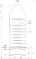
FIG. 1 is a front view of a bottle as an embodiment. -
FIG. 2 is a top view of a bottle as an embodiment. -
FIG. 3 is a cross-sectional view of the bottle inFIG. 2 as taken along line III-III. -
FIG. 4 is a front view of a bottle as Comparative Example 1. -
FIG. 5 is a front view of a bottle as Comparative Example 2. -
FIG. 6 is a diagram illustrating how a lateral load test was conducted. - The description below deals with a plastic bottle as an embodiment of the present invention with reference to drawings. The description below deals with, as an example plastic bottle according to the present invention, a
plastic bottle 1 configured to contain a liquid product for distribution and sale (hereinafter referred to simply as "bottle 1 "). - The
bottle 1 as the present embodiment is made of polyethylene terephthalate, and is a colorless, transparent container. Thebottle 1 is produced from a polyethylene terephthalate preform by biaxially oriented blow molding. The bottle is not necessarily made of polyethylene terephthalate, and may alternatively be made of polyethylene or polypropylene, for example. - The
bottle 1 as the present embodiment has a capacity of 2 L. Thebottle 1 may, however, have any capacity. The capacity may be approximately from 200 mL to 2 L such as 280 mL, 350 mL, or 500 mL, as of a common plastic bottle. - The
bottle 1 is intended to be filled with a liquid product, examples of which include (i) beverages such as soft drinks (for example, carbonated drinks, fruit-based drinks, coffee beverages, tea-based drinks, mineral water, soy milk based drinks, vegetable-based drinks, sports drinks, and cocoa beverages), alcoholic beverages, and milk beverages, (ii) liquid foods such as soup, and (iii) liquid seasonings such as Worcester sauce and soy sauce. - The
bottle 1 as the present embodiment includes amouth 2, ashoulder 3, abody 4, and a bottom 5 (seeFig. 1 ). The description below, in referring to the up-down direction of thebottle 1, assumes that thebottle 1 is oriented with thebottom 5 in contact with the ground on which thebottle 1 is placed (that is, thebottle 1 is oriented as illustrated inFig. 1 ). In other words, themouth 2 is on the upper side of thebottle 1, whereas thebottom 5 is on the lower side of thebottle 1. Further, the lateral direction (or horizontal direction) of thebottle 1 is orthogonal to the up-down direction; in other words, it is the left-right direction inFig. 1 or the direction orthogonal to the drawing. - The
bottle 1 is substantially rectangular as viewed from above (seeFig. 2 ). This means that thebottle 1 has a substantially rectangular transverse cross-sectional shape at each of theshoulder 3, thebody 4, and thebottom 5. The expression "substantially rectangular" indicates that the shape is not necessarily rectangular as technically defined in a mathematical sense and may be essentially rectangular with rounded corners and/or the like as of an industrial product. - The
mouth 2 has an opening for entry of a liquid product to be charged into thebottle 1 and exit of the liquid product having been charged. Themouth 2 has an outer surface provided with an external thread engageable with a cap (not illustrated in the drawings). Theshoulder 3 is that portion of thebottle 1 which gradually increases in size from themouth 2 to thebody 4. Thebottom 5 is, when thebottle 1 is placed on a surface such as a tabletop, in contact with that surface. Themouth 2, theshoulder 3, and thebottom 5 are similar in structure and function to those of a publicly known plastic bottle, and are not described in detail herein. - The
bottle 1 as the present embodiment is configured such that thebody 4 has adepression 41, a plurality oflinear ribs 42, acushion 43, and awavy rib 44. - The
depression 41 is in an upper portion of thebody 4. Thedepression 41 has a two-stage depression structure including a first-stage section 41a receding inward of thebottle 1 and two second-stage sections 41b each receding further inward of thebottle 1 from the first-stage section 41a. The first-stage section 41a extends entirely around thebody 4. The second-stage sections 41b are each on one of those twofaces 4a of thebody 4 which correspond to the long sides of the transverse cross-sectional shape. The user can catch one of the second-stage sections 41b with the thumb and the other second-stage section 41b with a finger such as the index finger or middle finger to hold thebottle 1 in a stable orientation. In this state, the palm is along that portion of the first-stage section 41a which is on aface 4b of thebody 4, theface 4b corresponding to a short side of the transverse cross-sectional shape. As described above, thedepression 41 helps the user to hold thebottle 1 stably. - The plurality of (for the present embodiment, six)
linear ribs 42 are in a vertically central portion of thebody 4. Thelinear ribs 42 each extend horizontally and entirely around thebody 4. Thelinear ribs 42 reinforce thebody 4. - The
linear ribs 42 for the present embodiment each have a depth DL of 2.5 mm and an up-down width WL of 8 mm (seeFig. 3 ). The depth of a linear rib refers to how much the linear rib recedes inward of thebottle 1 relative to the outermost surface of thebody 4. The up-down width of a linear rib refers to the dimension that the linear rib has on its open side along the outermost surface of thebody 4. - The
cushion 43 and thewavy rib 44 are in a lower portion of thebody 4. Thecushion 43 has (i) agroove 43a extending entirely around thebody 4 and (ii) twosmall recesses 43b extending entirely around thebody 4, one of which is above thegroove 43a and the other of which is below thegroove 43a. Thegroove 43a and thesmall recesses 43b are ribs in actuality although they are termed differently for discrimination. Thecushion 43, which has agroove 43a and twosmall recesses 43b, may itself be regarded as a single rib. - The
cushion 43 is shaped to have a position in the up-down direction which position varies continuously around thebody 4. Specifically, thecushion 43 is in the shape of a wave around thebody 4, the wave being convex downward at thecorners 4c, which correspond to the respective vertices of the transverse cross-sectional shape of thebody 4. In other words, thecushion 43 has a height H1 above a height H2, where H1 denotes the portions of thecushion 43 on therespective faces body 4, and H2 denotes the portions of thecushion 43 at therespective corners 4c, which correspond to the vertices of the transverse cross-sectional shape of the body 4 (seeFigs. 1 to 3 ). The position of thecushion 43 in the up-down direction is represented by the position of a vertically central portion of thegroove 43a in the up-down direction. - The
groove 43a has a depth D1 of 4.7 mm. Thesmall recesses 43b each have a depth D2 of 2 mm, which is smaller than the depth D1 of thegroove 43a (seeFig. 3 ). As described above, thecushion 43 has a relativelydeep groove 43a and two relatively shallowsmall recesses 43b, one of which is above thegroove 43a and the other of which is below thegroove 43a. This allows thegroove 43a and thesmall recesses 43b to act integrally as a spring, which allows thecushion 43 to, in response to an external force being applied to thebottle 1, move in such a manner as to absorb the external force and thereby prevent thebottle 1 as a whole from being greatly deformed by the external force. Thecushion 43 being in the shape of a wave prevents deformation of thebottle 1 regardless of whether the external force is applied to thebottle 1 in the up-down direction or in the lateral direction. - The
groove 43a and thesmall recesses 43b are separated from each other by a boundary portion that recedes inward from the outer surface of thebody 4. This allows thegroove 43a and thesmall recesses 43b to act integrally as a spring, - The
cushion 43 as a whole has an up-down width W (a dimension in the up-down direction) of 16 mm. Thegroove 43a has an up-down width W1 (a dimension in the up-down direction) of 7 mm. Thesmall recesses 43b each have an up-down width W2 of 3 mm (seeFig. 3 ). The up-down width W1 of thegroove 43a should, as in this example, preferably be not larger than 0.4 times the up-down width W of thecushion 43 as a whole. The up-down width W2 of eachsmall recess 43b is smaller than the up-down width W1 of thegroove 43a. - The boundary portion between the
groove 43a and eachsmall recess 43b has a dimension in the up-down direction (i.e. an up-down width) of 1.5 mm, which is smaller than the up-down width W1 of thegroove 43a. Thegroove 43a and thesmall recesses 43b are thus adjacent to each other with substantially no gap therebetween. This allows thegroove 43a and thesmall recesses 43b to act integrally as a spring. - The
wavy rib 44 is, similarly to thecushion 43, shaped to have a position in the up-down direction which position varies continuously around thebody 4. Thewavy rib 44 differs from thecushion 43 in that it is a single rib. Thewavy rib 44 is similar to thecushion 43 in that the portions on therespective faces respective corners 4c. - Finally, the description below deals with plastic bottles as other embodiments of the present invention. The arrangement disclosed for any embodiment below is combinable with the arrangement disclosed for any other embodiment unless such a combination causes any inconvenience.
- The embodiment described above is an
example bottle 1 having a substantially rectangular transverse cross-sectional shape at each of theshoulder 3, thebody 4, and thebottom 5. The plastic bottle according to the present invention, however, does not necessarily have a particular transverse cross-sectional shape at each section; the transverse cross-sectional shape may be circular or polygonal, for example. The terms "circular" and "polygonal" refer to not only the shapes as technically defined in a mathematical sense, but also such shapes with additional deformation imparted for industrial application, as noted above about the expression "substantially rectangular". Further, the plastic bottle may have a transverse cross-sectional shape that varies according to the position in the up-down direction; for instance, the plastic bottle may have a circular transverse cross-sectional shape at an upper portion and a polygonal transverse cross-sectional shape at a lower portion. The portion of the body in which the cushion is disposed may also have any transverse cross-sectional shape, but should preferably have a substantially rectangular transverse cross-sectional shape. - The embodiment described above is an example including a
cushion 43 having a position in the up-down direction which position varies continuously such that the portions on therespective faces respective corners 4c. The plastic bottle according to the present invention is, however, configured such that the cushion has any position in the up-down direction as long as the position varies continuously around the body. If the cushion is in the shape of a wave, that is, it includes alternating upper and lower portions in the up-down direction, the wave should preferably have vertices at the respective corners of the body to facilitate load absorption. The vertices may, in that case, be convex downward (as in the embodiment described above) or upward. - The embodiment described above is an example including a
cushion 43 at a lower portion of thebody 4. The plastic bottle according to the present invention is, however, configured such that the cushion may be at any position in the up-down direction. The cushion may thus be positioned in view of a factor only distantly related to the main function of the cushion (such as the appearance of the plastic bottle or how the linear ribs should be positioned for the plastic bottle as a whole to have a higher strength). - The embodiment described above is an example in which the
groove 43a and thesmall recesses 43b are separated from each other by a boundary portion that recedes inward from the outer surface of thebody 4. The plastic bottle according to the present invention may, however, be configured such that thegroove 43a and thesmall recesses 43b are separated from each other by a boundary portion that is flush with the outer surface of thebody 4. Further, thegroove 43a, thesmall recesses 43b, and the boundary portion are not necessarily sized relative to one another as in the example above. - The plastic bottle according to the present invention is configured such that the groove and the small recesses may each have a constant or varying depth and width. The groove and the small recesses may each, in the case of having a varying depth, have a depth that varies in the form of a wave, for example. This applies to the width as well. Further, the groove and the small recesses may each have a depth and a width both of which vary in the shape of a wave.
- It should be understood that with respect to other arrangements as well, the embodiments disclosed herein are illustrative in all respects and do not limit the scope of the present invention. Persons skilled in the art will readily understand that the present invention can be modified as appropriate without departing from the scope of the present invention. The present invention thus naturally covers in its scope any embodiment as modified without departing from the scope of the present invention.
- The description below deals with the present invention in greater detail on the basis of Examples. The present invention is, however, not limited by the Examples below.
- The
bottle 1 as the embodiment described above was used as an Example. Thebottle 1 had a capacity of 2 L as mentioned above. - Comparative Example 1 was a
bottle 1A with a linear cushion 45 instead of thecushion 43 for the embodiment described above (seeFig. 4 ). The cushion 45 for Comparative Example 1 included a groove 45a andsmall recesses 45b each extending horizontally and entirely around thebody 4. Comparative Example 1 thus differed from the Example on whether the position of the cushion in the up-down direction varied around the body. Thebottle 1A as Comparative Example 1 also had a capacity of 2 L. - Comparative Example 2 was a
bottle 1B with an additionalwavy rib 44 instead of thecushion 43 for the embodiment described above (seeFig. 5 ). The additionalwavy rib 44 for Comparative Example 2 was configured similarly to thewavy rib 44 for the embodiment described above. Thebottle 1B as Comparative Example 2, in other words, had twowavy ribs 44. Comparative Example 2 differed from the Example in that the former did not include a cushion. Thebottle 1B as Comparative Example 2 also had a capacity of 2 L. - The respective bottles of the Example and Comparative Examples were each filled with 2 L of water, placed to stand with the bottom 5 on the ground and subjected to a load in the up-down direction for a load-displacement measurement. The resulting load-displacement curve had a point at which the displacement stopped being proportional to the load (the point corresponding to the yield point in a load-displacement measurement for material evaluation). The bottles were each regarded as starting to buckle at the point, so that the load at the point was regarded as a buckling load. This test was conducted three times for each of the Example and Comparative Examples. The average of the respective measurements in the individual instances of the test was used as the test result. The results of the Example and Comparative Examples are shown in Table 1.
-
[Table 1] Example Comparative Example 1 Comparative Example 2 Buckling load [N] 641 644 481 - Table 1 shows that Comparative Example 2, which did not include a cushion, had a low buckling load (that is, it easily buckled) as compared to the Example and Comparative Example 1, each of which did include a cushion. The results indicate that the respective bottles of the Example and Comparative Example 1, each of which included a cushion, did not easily buckle.
- The respective bottles of the Example and Comparative Example 1 were each filled with 2 L of water, laid with the upper and lower ends of the body 4 (specifically, a
face 4a thereof) supported, and subjected to a downward load at a vertically central portion of the body 4 (seeFig. 6 ). The test used the device illustrated inFig. 6 , which included a push-pull gauge P movable in the up-down direction and a vernier caliper N with a jaw N1 movable in the up-down direction to follow the push-pull gauge P for determination of the amount of movement of the push-pull gauge P. The amount by which the push-pull gauge P moved (that is, the measurement of the vernier caliper N) by the time the load (that is, the measurement of the push-pull gauge P) reached 50 N was regarded as the amount of deformation of the bottle. This test was conducted five times for each of the Example and Comparative Example 1. The average of the respective measurements in the individual instances of the test was used as the test result. The results of the Example and Comparative Example 1 are shown in Table 2. -
[Table 2] Example Comparative Example 1 Deformation amount [mm] 6.92 7.68 - Table 2 shows that Comparative Example 1, which included a horizontal cushion, was easily deformed by a lateral load as compared to the Example, which included a wavy cushion. The results indicate that a cushion whose position in the up-down direction varies around the body as of the Example reinforces a bottle against both a vertical load and a lateral load.
- The present invention is applicable to, for example, a container configured to be filled with a liquid product such as a beverage.
-
- 1
- Plastic bottle
- 2
- Mouth
- 3
- Shoulder
- 4
- Body
- 4a
- Face (long side)
- 4b
- Face (short side)
- 4c
- Corner
- 41
- Depression
- 41a
- First-stage section
- 41b
- Second-stage section
- 42
- Linear rib
- 43
- Cushion
- 43a
- Groove
- 43b
- Small recess
- 44
- Wavy rib
- 45
- Cushion (Comparative Example 1)
- 45a
- Groove (Comparative Example 1)
- 45b
- Small recess (Comparative Example 1)
- 5
- Bottom
- N
- Vernier caliper
- P
- Push-pull gauge
Claims (6)
- A plastic bottle, comprising:a body including a cushion,the cushion having a groove extending entirely around the body, a first small recess disposed above the groove and extending entirely around the body, and a second small recess disposed below the groove and extending entirely around the body, the first and second small recesses being shallower than the groove,the cushion being shaped to have a position in an up-down direction which position varies continuously.
- The plastic bottle according to claim 1, wherein
the groove and each of the first and second small recesses are separated from each other by a boundary portion having a dimension in the up-down direction which dimension is smaller than a dimension of the groove in the up-down direction. - The plastic bottle according to claim 1 or 2, wherein
the cushion is disposed at a portion of the body which portion has a substantially rectangular transverse cross-sectional shape. - The plastic bottle according to claim 3, wherein
the cushion is in a shape of a wave including alternating upper and lower portions in the up-down direction and having vertices at respective corners of the body. - The plastic bottle according to any one of claims 1 to 4, wherein
the groove has a depth of 3 mm to 10 mm. - The plastic bottle according to any one of claims 1 to 5, wherein
the groove has a dimension of 3 mm to 10 mm in the up-down direction.
Applications Claiming Priority (2)
| Application Number | Priority Date | Filing Date | Title |
|---|---|---|---|
| JP2021063027A JP7586755B2 (en) | 2021-04-01 | 2021-04-01 | Plastic Bottles |
| PCT/JP2022/007946 WO2022209488A1 (en) | 2021-04-01 | 2022-02-25 | Plastic bottle |
Publications (3)
| Publication Number | Publication Date |
|---|---|
| EP4253265A1 true EP4253265A1 (en) | 2023-10-04 |
| EP4253265A4 EP4253265A4 (en) | 2024-11-06 |
| EP4253265B1 EP4253265B1 (en) | 2026-07-22 |
Family
ID=83458422
Family Applications (1)
| Application Number | Title | Priority Date | Filing Date |
|---|---|---|---|
| EP22779713.1A Active EP4253265B1 (en) | 2021-04-01 | 2022-02-25 | Plastic bottle |
Country Status (3)
| Country | Link |
|---|---|
| EP (1) | EP4253265B1 (en) |
| JP (1) | JP7586755B2 (en) |
| WO (1) | WO2022209488A1 (en) |
Family Cites Families (11)
| Publication number | Priority date | Publication date | Assignee | Title |
|---|---|---|---|---|
| US1051363A (en) | 1912-01-05 | 1913-01-21 | Emil Anderson | Generator. |
| US20090166314A1 (en) * | 2007-12-28 | 2009-07-02 | The Coca-Cola Company | Plastic bottle |
| JP5143686B2 (en) * | 2008-09-24 | 2013-02-13 | ザ コカ・コーラ カンパニー | Plastic bottle |
| JP5065363B2 (en) * | 2009-12-07 | 2012-10-31 | 麒麟麦酒株式会社 | Square beverage plastic container and beverage product using the same |
| JP5584929B2 (en) * | 2010-12-17 | 2014-09-10 | サントリーホールディングス株式会社 | Resin container |
| JP2013154907A (en) * | 2012-01-30 | 2013-08-15 | Yoshino Kogyosho Co Ltd | Bottle |
| JP6388467B2 (en) | 2012-12-03 | 2018-09-12 | サントリーホールディングス株式会社 | Resin container |
| JP6157348B2 (en) * | 2013-12-27 | 2017-07-05 | サントリー食品インターナショナル株式会社 | Resin container |
| JP2018140824A (en) * | 2017-02-28 | 2018-09-13 | サントリーホールディングス株式会社 | Resin container |
| JP6403823B2 (en) * | 2017-03-21 | 2018-10-10 | サントリーホールディングス株式会社 | Resin container |
| EP3784578B1 (en) * | 2018-04-26 | 2023-05-03 | Société des Produits Nestlé S.A. | Container grip portion with reinforcing ribs |
-
2021
- 2021-04-01 JP JP2021063027A patent/JP7586755B2/en active Active
-
2022
- 2022-02-25 EP EP22779713.1A patent/EP4253265B1/en active Active
- 2022-02-25 WO PCT/JP2022/007946 patent/WO2022209488A1/en not_active Ceased
Also Published As
| Publication number | Publication date |
|---|---|
| EP4253265B1 (en) | 2026-07-22 |
| JP2022158261A (en) | 2022-10-17 |
| JP7586755B2 (en) | 2024-11-19 |
| EP4253265A4 (en) | 2024-11-06 |
| WO2022209488A1 (en) | 2022-10-06 |
Similar Documents
| Publication | Publication Date | Title |
|---|---|---|
| US20240150063A1 (en) | Plastic Container With Strapped Base | |
| US20230202704A1 (en) | Plastic Container with Strapped Based | |
| CA2748264C (en) | Hot-fill container | |
| EP1365961B1 (en) | Blow molded slender grippable bottle having dome with flex panels | |
| CA2785772C (en) | Hot-fill container having flat panels | |
| US7080747B2 (en) | Lightweight container | |
| JP5030823B2 (en) | Plastic container having buckling resistance and beverage product using the same | |
| US7874442B2 (en) | Hot-fill plastic container with ribs and grip | |
| US8991628B2 (en) | Hot-fill jar base | |
| US20100326951A1 (en) | Lightweight, high strength bottle | |
| KR101496159B1 (en) | A bottleneck | |
| AU2002240230A1 (en) | Blow molded slender grippable bottle having dome with flex panels | |
| US10053275B2 (en) | Deformation-resistant container with panel indentations | |
| AU2011342160A1 (en) | Resin container | |
| US11312557B2 (en) | Container with pressure accommodation panel | |
| EP3397565B1 (en) | Plastic bottle with an annular gripping portion | |
| US6082546A (en) | Shock-resistant container | |
| JP7586755B2 (en) | Plastic Bottles | |
| EP3514075B1 (en) | Resin-made bottle |
Legal Events
| Date | Code | Title | Description |
|---|---|---|---|
| STAA | Information on the status of an ep patent application or granted ep patent |
Free format text: STATUS: THE INTERNATIONAL PUBLICATION HAS BEEN MADE |
|
| PUAI | Public reference made under article 153(3) epc to a published international application that has entered the european phase |
Free format text: ORIGINAL CODE: 0009012 |
|
| STAA | Information on the status of an ep patent application or granted ep patent |
Free format text: STATUS: REQUEST FOR EXAMINATION WAS MADE |
|
| 17P | Request for examination filed |
Effective date: 20230629 |
|
| AK | Designated contracting states |
Kind code of ref document: A1 Designated state(s): AL AT BE BG CH CY CZ DE DK EE ES FI FR GB GR HR HU IE IS IT LI LT LU LV MC MK MT NL NO PL PT RO RS SE SI SK SM TR |
|
| DAV | Request for validation of the european patent (deleted) | ||
| DAX | Request for extension of the european patent (deleted) | ||
| A4 | Supplementary search report drawn up and despatched |
Effective date: 20241004 |
|
| RIC1 | Information provided on ipc code assigned before grant |
Ipc: B65D 1/02 20060101ALI20240927BHEP Ipc: B65D 1/44 20060101AFI20240927BHEP |
|
| STAA | Information on the status of an ep patent application or granted ep patent |
Free format text: STATUS: EXAMINATION IS IN PROGRESS |
|
| 17Q | First examination report despatched |
Effective date: 20250509 |
|
| GRAP | Despatch of communication of intention to grant a patent |
Free format text: ORIGINAL CODE: EPIDOSNIGR1 |
|
| STAA | Information on the status of an ep patent application or granted ep patent |
Free format text: STATUS: GRANT OF PATENT IS INTENDED |
|
| INTG | Intention to grant announced |
Effective date: 20260211 |
|
| GRAS | Grant fee paid |
Free format text: ORIGINAL CODE: EPIDOSNIGR3 |
|
| GRAA | (expected) grant |
Free format text: ORIGINAL CODE: 0009210 |
|
| STAA | Information on the status of an ep patent application or granted ep patent |
Free format text: STATUS: THE PATENT HAS BEEN GRANTED |
|
| P01 | Opt-out of the competence of the unified patent court (upc) registered |
Free format text: CASE NUMBER: UPC_APP_0017778_4253265/2026 Effective date: 20260609 |
|
| AK | Designated contracting states |
Kind code of ref document: B1 Designated state(s): AL AT BE BG CH CY CZ DE DK EE ES FI FR GB GR HR HU IE IS IT LI LT LU LV MC MK MT NL NO PL PT RO RS SE SI SK SM TR |
|
| REG | Reference to a national code |
Ref country code: CH Ref legal event code: F10 Free format text: ST27 STATUS EVENT CODE: U-0-0-F10-F00 (AS PROVIDED BY THE NATIONAL OFFICE) Effective date: 20260722 Ref country code: GB Ref legal event code: FG4D |
|
| REG | Reference to a national code |
Ref country code: DE Ref legal event code: R096 Ref document number: 602022040270 Country of ref document: DE |
|
| REG | Reference to a national code |
Ref country code: IE Ref legal event code: FG4D |