EP4253256A1 - Method for temporarily closing openings in aircraft parts - Google Patents
Method for temporarily closing openings in aircraft parts Download PDFInfo
- Publication number
- EP4253256A1 EP4253256A1 EP22165990.7A EP22165990A EP4253256A1 EP 4253256 A1 EP4253256 A1 EP 4253256A1 EP 22165990 A EP22165990 A EP 22165990A EP 4253256 A1 EP4253256 A1 EP 4253256A1
- Authority
- EP
- European Patent Office
- Prior art keywords
- opening
- rfid tag
- closure member
- temporary
- temporary closure
- Prior art date
- Legal status (The legal status is an assumption and is not a legal conclusion. Google has not performed a legal analysis and makes no representation as to the accuracy of the status listed.)
- Granted
Links
Images

Classifications
-
- G—PHYSICS
- G05—CONTROLLING; REGULATING
- G05B—CONTROL OR REGULATING SYSTEMS IN GENERAL; FUNCTIONAL ELEMENTS OF SUCH SYSTEMS; MONITORING OR TESTING ARRANGEMENTS FOR SUCH SYSTEMS OR ELEMENTS
- G05B19/00—Program-control systems
- G05B19/02—Program-control systems electric
- G05B19/418—Total factory control, i.e. centrally controlling a plurality of machines, e.g. direct or distributed numerical control [DNC], flexible manufacturing systems [FMS], integrated manufacturing systems [IMS] or computer integrated manufacturing [CIM]
- G05B19/41805—Total factory control, i.e. centrally controlling a plurality of machines, e.g. direct or distributed numerical control [DNC], flexible manufacturing systems [FMS], integrated manufacturing systems [IMS] or computer integrated manufacturing [CIM] characterised by assembly
-
- B—PERFORMING OPERATIONS; TRANSPORTING
- B64—AIRCRAFT; AVIATION; COSMONAUTICS
- B64F—GROUND OR AIRCRAFT-CARRIER-DECK INSTALLATIONS SPECIALLY ADAPTED FOR USE IN CONNECTION WITH AIRCRAFT; DESIGNING, MANUFACTURING, ASSEMBLING, CLEANING, MAINTAINING OR REPAIRING AIRCRAFT, NOT OTHERWISE PROVIDED FOR; HANDLING, TRANSPORTING, TESTING OR INSPECTING AIRCRAFT COMPONENTS, NOT OTHERWISE PROVIDED FOR
- B64F5/00—Designing, manufacturing, assembling, cleaning, maintaining or repairing aircraft, not otherwise provided for; Handling, transporting, testing or inspecting aircraft components, not otherwise provided for
- B64F5/10—Manufacturing or assembling aircraft, e.g. jigs therefor
-
- F—MECHANICAL ENGINEERING; LIGHTING; HEATING; WEAPONS; BLASTING
- F16—ENGINEERING ELEMENTS AND UNITS; GENERAL MEASURES FOR PRODUCING AND MAINTAINING EFFECTIVE FUNCTIONING OF MACHINES OR INSTALLATIONS; THERMAL INSULATION IN GENERAL
- F16B—DEVICES FOR FASTENING OR SECURING CONSTRUCTIONAL ELEMENTS OR MACHINE PARTS TOGETHER, e.g. NAILS, BOLTS, CIRCLIPS, CLAMPS, CLIPS OR WEDGES; JOINTS OR JOINTING
- F16B19/00—Bolts without screw-thread; Pins, including deformable elements; Rivets
- F16B19/04—Rivets; Spigots or the like fastened by riveting
- F16B19/08—Hollow rivets; Multi-part rivets
- F16B19/10—Hollow rivets; Multi-part rivets fastened by expanding mechanically
- F16B19/1027—Multi-part rivets
- F16B19/1036—Blind rivets
- F16B19/109—Temporary rivets, e.g. with a spring-loaded pin
-
- F—MECHANICAL ENGINEERING; LIGHTING; HEATING; WEAPONS; BLASTING
- F16—ENGINEERING ELEMENTS AND UNITS; GENERAL MEASURES FOR PRODUCING AND MAINTAINING EFFECTIVE FUNCTIONING OF MACHINES OR INSTALLATIONS; THERMAL INSULATION IN GENERAL
- F16B—DEVICES FOR FASTENING OR SECURING CONSTRUCTIONAL ELEMENTS OR MACHINE PARTS TOGETHER, e.g. NAILS, BOLTS, CIRCLIPS, CLAMPS, CLIPS OR WEDGES; JOINTS OR JOINTING
- F16B5/00—Joining sheets or plates, e.g. panels, to one another or to strips or bars parallel to them
- F16B5/02—Joining sheets or plates, e.g. panels, to one another or to strips or bars parallel to them by means of fastening members using screw-thread
-
- F—MECHANICAL ENGINEERING; LIGHTING; HEATING; WEAPONS; BLASTING
- F16—ENGINEERING ELEMENTS AND UNITS; GENERAL MEASURES FOR PRODUCING AND MAINTAINING EFFECTIVE FUNCTIONING OF MACHINES OR INSTALLATIONS; THERMAL INSULATION IN GENERAL
- F16B—DEVICES FOR FASTENING OR SECURING CONSTRUCTIONAL ELEMENTS OR MACHINE PARTS TOGETHER, e.g. NAILS, BOLTS, CIRCLIPS, CLAMPS, CLIPS OR WEDGES; JOINTS OR JOINTING
- F16B5/00—Joining sheets or plates, e.g. panels, to one another or to strips or bars parallel to them
- F16B5/04—Joining sheets or plates, e.g. panels, to one another or to strips or bars parallel to them by means of riveting
-
- G—PHYSICS
- G05—CONTROLLING; REGULATING
- G05B—CONTROL OR REGULATING SYSTEMS IN GENERAL; FUNCTIONAL ELEMENTS OF SUCH SYSTEMS; MONITORING OR TESTING ARRANGEMENTS FOR SUCH SYSTEMS OR ELEMENTS
- G05B19/00—Program-control systems
- G05B19/02—Program-control systems electric
- G05B19/418—Total factory control, i.e. centrally controlling a plurality of machines, e.g. direct or distributed numerical control [DNC], flexible manufacturing systems [FMS], integrated manufacturing systems [IMS] or computer integrated manufacturing [CIM]
- G05B19/41865—Total factory control, i.e. centrally controlling a plurality of machines, e.g. direct or distributed numerical control [DNC], flexible manufacturing systems [FMS], integrated manufacturing systems [IMS] or computer integrated manufacturing [CIM] characterised by job scheduling, process planning, material flow
-
- G—PHYSICS
- G06—COMPUTING OR CALCULATING; COUNTING
- G06K—GRAPHICAL DATA READING; PRESENTATION OF DATA; RECORD CARRIERS; HANDLING RECORD CARRIERS
- G06K19/00—Record carriers for use with machines and with at least a part designed to carry digital markings
- G06K19/06—Record carriers for use with machines and with at least a part designed to carry digital markings characterised by the kind of the digital marking, e.g. shape, nature, code
- G06K19/067—Record carriers with conductive marks, printed circuits or semiconductor circuit elements, e.g. credit or identity cards also with resonating or responding marks without active components
- G06K19/07—Record carriers with conductive marks, printed circuits or semiconductor circuit elements, e.g. credit or identity cards also with resonating or responding marks without active components with integrated circuit chips
- G06K19/077—Constructional details, e.g. mounting of circuits in the carrier
- G06K19/07749—Constructional details, e.g. mounting of circuits in the carrier the record carrier being capable of non-contact communication, e.g. constructional details of the antenna of a non-contact smart card
- G06K19/07758—Constructional details, e.g. mounting of circuits in the carrier the record carrier being capable of non-contact communication, e.g. constructional details of the antenna of a non-contact smart card arrangements for adhering the record carrier to further objects or living beings, functioning as an identification tag
- G06K19/0776—Constructional details, e.g. mounting of circuits in the carrier the record carrier being capable of non-contact communication, e.g. constructional details of the antenna of a non-contact smart card arrangements for adhering the record carrier to further objects or living beings, functioning as an identification tag the adhering arrangement being a layer of adhesive, so that the record carrier can function as a sticker
-
- F—MECHANICAL ENGINEERING; LIGHTING; HEATING; WEAPONS; BLASTING
- F16—ENGINEERING ELEMENTS AND UNITS; GENERAL MEASURES FOR PRODUCING AND MAINTAINING EFFECTIVE FUNCTIONING OF MACHINES OR INSTALLATIONS; THERMAL INSULATION IN GENERAL
- F16B—DEVICES FOR FASTENING OR SECURING CONSTRUCTIONAL ELEMENTS OR MACHINE PARTS TOGETHER, e.g. NAILS, BOLTS, CIRCLIPS, CLAMPS, CLIPS OR WEDGES; JOINTS OR JOINTING
- F16B11/00—Connecting constructional elements or machine parts by sticking or pressing them together, e.g. cold pressure welding
- F16B11/006—Connecting constructional elements or machine parts by sticking or pressing them together, e.g. cold pressure welding by gluing
-
- F—MECHANICAL ENGINEERING; LIGHTING; HEATING; WEAPONS; BLASTING
- F16—ENGINEERING ELEMENTS AND UNITS; GENERAL MEASURES FOR PRODUCING AND MAINTAINING EFFECTIVE FUNCTIONING OF MACHINES OR INSTALLATIONS; THERMAL INSULATION IN GENERAL
- F16B—DEVICES FOR FASTENING OR SECURING CONSTRUCTIONAL ELEMENTS OR MACHINE PARTS TOGETHER, e.g. NAILS, BOLTS, CIRCLIPS, CLAMPS, CLIPS OR WEDGES; JOINTS OR JOINTING
- F16B2200/00—Constructional details of connections not covered for in other groups of this subclass
- F16B2200/95—Constructional details of connections not covered for in other groups of this subclass with markings, colours, indicators or the like
Definitions
- the invention relates to a method for temporarily closing openings during a manufacturing process.
- the invention provides a method for temporarily closing openings in a part, preferably an aircraft part, during a manufacturing process, the method comprising:
- step a) comprises providing a second part having at least one second opening and aligning at least one pair of first and second openings.
- the temporary closure member is configured as an adhesive strip and removable attached to the first part and/or second part by adhesive bonding such that the first and/or second openings are closed, wherein the RFID tag is integrated into the adhesive strip.
- the temporary closure member is configured as a temporary fastener that is getting inserted into the first and/or second openings such that the respective opening is closed and the first and second parts are removable fastened to each other by positive locking and/or friction locking.
- step c) comprises including a scannable information tag that includes information indicative of an RFID frequency and/or the unique identification of the respective RFID tag into technical drawing data.
- step d) comprises scanning the information tag from the technical drawings and finding the RFID tag based on that information.
- step d) comprises the permanent member being configured as a bolt or rivet that is permanently installed in the first and/or second opening, preferably to fasten the second part to the first part.
- the first part is a primary structure part of an aircraft and the second part is a secondary structure part of an aircraft.
- the first part is a duct and the temporary closure member is a plug inserted such that the duct is closed.
- the adhesive strip can marker an area to make a reservation for a later installation of a part (e.g. bracket).
- the RFID tag functions as a digital marker and can have different applications and configurations, such as a pendant, integrated chip or the like, but all are collectively designated as RFID tag independent of their actual embodiment.
- a temporary closure member is a temporary fastener, such as spring cleco fasteners (also sometimes called cleko fasteners).
- the RFID tag may be integrated into the fastener or attached to it as a pendant.
- a temporary closure member is a remove before flight tag that also has an RFID tag (integrated or attached).
- the temporary closure members can be equipped to any kind of temporary configuration during an aircraft manufacturing process, e.g. plugs for air-conditioning ducts etc.
- the holes/openings can be tagged for example with a spring cleco sheet metal fastener.
- This temporary fastener can have an RFID tag that is configured as a pendant equipped with an RFID chip.
- the RFID tag can be detected in a later production step, to find the temporarily fastened/closed openings.
- the cleko fastener are an example. Other types of temporary sheet metal fasteners can be used.
- open holes are usually not acceptable from the point of view of stress, e.g. related to fatigue issues. With the temporary plug installation as disclosed herein these issues are avoided. At an early stage of the production, usually a lot of holes will be drilled and closed with temporary fasteners. Later during production, some of the holes have to be reopened, since the rivet position is used for additional parts to install e.g. brackets.
- a part can be attached in any of several ways, e.g. the part can be attached using a sheet metal temporary fastener with an RFID pendant, a sheet metal temporary fastener having an integrated RFID tag.
- the hole can also be closed with a security seal having an attached or integrated RFID tag.
- a QR code on a technical drawing facilitates identification of the type of RFID chip frequency or (unique) identification number.
- the temporary closure member may have an eye-catching colour to get attention (yellow or fluorescent).
- the temporary closure member may have an integrated optional flashlight.
- the RFID tag is waterproof (e.g. IP67). The measures described herein are applicable to other temporary aircraft installations during production.
- Some holes require high effort to find by a visual inspection. With the hole having an additional digital marker it can be easier detected.
- the temporary tagging of the hole can be detected with an appropriate electronic device (e.g. RFID scanner) and reduces the effort to find the holes that are to be opened.
- An RFID or other kind of electronic transmitter (collectively designated RFID tag herein) is used to mark the hole.
- the electronic scanner can detect the position of the marked hole, preferably based on its unique identification and/or information from the technical drawing (cf. QR code).
- a first part 10 is provided.
- the first part 10 is preferably a primary structure part 12 of an aircraft (not shown).
- the first part 10 includes at least one first opening 14.
- a temporary closure member 16 is attached to the first part 10.
- the temporary closure member 16 is an adhesive strip 18.
- the temporary closure member 16 is attached such that the first opening 14 is covered by the temporary closure member 16.
- the temporary closure member 16 preferably has an easily noticeable colour, e.g. red.
- the temporary closure member 16 includes an RFID tag 20.
- the RFID tag 20 is preferably integrated into the temporary closure member 16.
- the RFID tag 20 may be attached to the temporary closure member 16 as a separate element.
- a unique identification (unique ID) is associated with the location of the closed opening and stored on the RFID tag 20.
- unique ID and/or the location of the temporary closure member 16 are also stored in a database and included into technical drawings for subsequent manufacturing.
- the frequency of the RFID tag 20 can be stored. This information may be stored as scannable information, e.g. in a QR code.
- the first opening 14 is to be permanently closed off.
- a worker uses an RFID scanner and scans for the temporary closure member 16 based on the information stored in the database or technical drawings. The worker finds the temporary closure member 16 and removes it. Where necessary a solvent may be used.
- a permanent member 22 is inserted in to the first opening 14 and fixed therein.
- the permanent member 22 is a permanent plug 24 that closes the first opening 14.
- the first part 10 is preferably a primary structure part 12 of an aircraft (not shown).
- the first part 10 includes at least one first opening 14.
- the second part 11 is preferably a secondary structure part 13 of the aircraft.
- the second part 11 includes at least one second opening 15.
- the second part 11 may be a mounting bracket, for example.
- the first and second parts 10, 11 are arranged such that the at least one pair of first and second openings 14, 15 are aligned.
- a temporary closure member 16 is inserted into the aligned pair of openings 14, 15.
- the temporary closure member 16 is attached such that the first and second opening 14, 15 are covered by the temporary closure member 16.
- the temporary closure member 16 preferably has an easily noticeable colour, e.g. red.
- the temporary closure member 16 is configured as a temporary fastener 26.
- the temporary fastener 26 comprises an actuation member 27 that actuates at least one locking member 28 between a locked and unlocked state. In the locked state the temporary fastener 26 is prohibited from moving along the axial direction of the pair of aligned openings 14, 15. In addition the temporary fastener 26 presses the first and second parts 10, 11 together so they are temporarily and removable fixed to each other.
- the temporary closure member 16 also includes an RFID tag 20.
- the RFID tag 20 is preferably integrated into the temporary closure member 16.
- the RFID tag 20 may be attached to the temporary closure member 16 as a separate element.
- a unique identification (unique ID) is associated with the location of the closed openings and stored on the RFID tag 20.
- unique ID and/or the location of the temporary closure member 16 are also stored in a database and included into technical drawings for subsequent manufacturing.
- the frequency of the RFID tag 20 can be stored. This information may be stored as scannable information, e.g. in a QR code.
- the first part 10 is to be permanently fixed to the second part 11.
- a worker uses an RFID scanner and scans for the temporary closure member 16 based on the information stored in the database or technical drawings. The worker finds the temporary closure member 16 and removes it by unlocking. Where necessary a special tool may be used.
- a permanent member 22 is inserted in to the first and second openings 14, 15 and fixed therein.
- the permanent member 22 is a rivet or a bolt 30 that fixes the first and second parts 10, 11 together.
- the invention proposes a method for temporarily closing openings in an aircraft part (10, 11) during a manufacturing process, by providing a first part (10) that has a first opening (14) and positioning a temporary closure member (16) insided that first opening (14).
- the temporary closing member (16) has an RFID tag (20) that has stored on it a unique identification.
- a scanning device is used to scan for the RFID tag (20) based on the identification.
- the temporary closure member (16) is removed from the first opening (14) and subsequently replaced by a permanent member (22).
Landscapes
- Engineering & Computer Science (AREA)
- General Engineering & Computer Science (AREA)
- Manufacturing & Machinery (AREA)
- Physics & Mathematics (AREA)
- General Physics & Mathematics (AREA)
- Mechanical Engineering (AREA)
- Quality & Reliability (AREA)
- Automation & Control Theory (AREA)
- Theoretical Computer Science (AREA)
- Microelectronics & Electronic Packaging (AREA)
- Computer Hardware Design (AREA)
- Transportation (AREA)
- Aviation & Aerospace Engineering (AREA)
- Automatic Assembly (AREA)
- Connection Of Plates (AREA)
Abstract
Description
- The invention relates to a method for temporarily closing openings during a manufacturing process.
- Currently, during aircraft manufacture and at an early stage of the production, a lot of holes are drilled and closed with fasteners. Later during production, some of the holes have to be reopened since the position is used for additional parts, e.g. brackets. However it is required that holes are not left open at the beginning of the production. Removing the fasteners at a later stage causes high effort with regards to manufacturing and production planning.
- It is the object of the invention to improve manufacturing of aircraft.
- The object of the invention is achieved by the subject-matter of the independent claims. Preferred embodiments are subject-matter of the dependent claims.
- The invention provides a method for temporarily closing openings in a part, preferably an aircraft part, during a manufacturing process, the method comprising:
- a) providing a first part having at least one first opening;
- b) positioning a temporary closure member so as to close the first opening, the closing member having an RFID tag;
- c) associating a unique identification with the first opening and storing the identification on the RFID tag;
- d) at a later stage, scanning for the RFID tag with an RFID scanning device based on the identification and removing the closure member from the first opening and installing a permanent member in the opening.
- Preferably, step a) comprises providing a second part having at least one second opening and aligning at least one pair of first and second openings.
- Preferably, in step b) the temporary closure member is configured as an adhesive strip and removable attached to the first part and/or second part by adhesive bonding such that the first and/or second openings are closed, wherein the RFID tag is integrated into the adhesive strip.
- Preferably, in step b) the temporary closure member is configured as a temporary fastener that is getting inserted into the first and/or second openings such that the respective opening is closed and the first and second parts are removable fastened to each other by positive locking and/or friction locking.
- Preferably, step c) comprises including a scannable information tag that includes information indicative of an RFID frequency and/or the unique identification of the respective RFID tag into technical drawing data.
- Preferably, step d) comprises scanning the information tag from the technical drawings and finding the RFID tag based on that information.
- Preferably, step d) comprises the permanent member being configured as a bolt or rivet that is permanently installed in the first and/or second opening, preferably to fasten the second part to the first part.
- Preferably, the first part is a primary structure part of an aircraft and the second part is a secondary structure part of an aircraft.
- Preferably, the first part is a duct and the temporary closure member is a plug inserted such that the duct is closed.
- One idea is using an adhesive strip or security seal equipped with an RFID tag as a temporary closure member. The adhesive strip can marker an area to make a reservation for a later installation of a part (e.g. bracket). The RFID tag functions as a digital marker and can have different applications and configurations, such as a pendant, integrated chip or the like, but all are collectively designated as RFID tag independent of their actual embodiment.
- Another possibility for a temporary closure member is a temporary fastener, such as spring cleco fasteners (also sometimes called cleko fasteners). The RFID tag may be integrated into the fastener or attached to it as a pendant.
- Another possibility for a temporary closure member is a remove before flight tag that also has an RFID tag (integrated or attached).
- The temporary closure members, as envisaged herein, can be equipped to any kind of temporary configuration during an aircraft manufacturing process, e.g. plugs for air-conditioning ducts etc.
- The holes/openings can be tagged for example with a spring cleco sheet metal fastener. This temporary fastener can have an RFID tag that is configured as a pendant equipped with an RFID chip. The RFID tag can be detected in a later production step, to find the temporarily fastened/closed openings. With the ideas presented here, it is possible to avoid removal of a permanent fastener.
- Another idea is to integrate the RFID function direct inside the fastener. The cleko fastener are an example. Other types of temporary sheet metal fasteners can be used.
- With the disclosure herein the removal of existing solid fasteners, as is a typical repetitive action during production of an aircraft, can be avoided. For example, during the primary structure assembly a lot of rivets are usually installed, but in some cases, a removal of some permanent rivets is necessary, e.g. for installing secondary structure parts. However, the removing of rivets causes extra work, effort and a possibility of oversize rivet installations. With the ideas presented herein, a technology is developed for avoiding extra work and effort.
- It should be noted that in the secondary structure, open holes are usually not acceptable from the point of view of stress, e.g. related to fatigue issues. With the temporary plug installation as disclosed herein these issues are avoided. At an early stage of the production, usually a lot of holes will be drilled and closed with temporary fasteners. Later during production, some of the holes have to be reopened, since the rivet position is used for additional parts to install e.g. brackets.
- With the temporary closure members the holes are closed from the beginning of the production. The association of RFID tags allow for a reliable and efficient removal of the temporary closure members and subsequent installation of the permanent members, e.g. rivets, bolts or plugs, as the case may be.
- The process steps can be summarized as follows:
- drilling of a hole in an early production step;
- installation of a temporary closure member with a digital marker (e.g. RFID tag);
- detection of the digital marker with an electronic device
- removal of the marker to use the holes, e.g. for installing another part
- In general, a part can be attached in any of several ways, e.g. the part can be attached using a sheet metal temporary fastener with an RFID pendant, a sheet metal temporary fastener having an integrated RFID tag. The hole can also be closed with a security seal having an attached or integrated RFID tag.
- A QR code on a technical drawing facilitates identification of the type of RFID chip frequency or (unique) identification number. The temporary closure member may have an eye-catching colour to get attention (yellow or fluorescent). The temporary closure member may have an integrated optional flashlight. Preferably, the RFID tag is waterproof (e.g. IP67). The measures described herein are applicable to other temporary aircraft installations during production.
- Some holes require high effort to find by a visual inspection. With the hole having an additional digital marker it can be easier detected. The temporary tagging of the hole can be detected with an appropriate electronic device (e.g. RFID scanner) and reduces the effort to find the holes that are to be opened. An RFID or other kind of electronic transmitter (collectively designated RFID tag herein) is used to mark the hole.
- The electronic scanner can detect the position of the marked hole, preferably based on its unique identification and/or information from the technical drawing (cf. QR code).
- With this it is easy to install for example a secondary structure bracket on a primary structure rivet pattern without having to remove the solid rivet on shell level. Rather, the temporary closure member is removed and the secondary structure bracket can be installed with permanent rivets.
- Embodiments of the invention are described in more detail with reference to the accompanying schematic drawings that are listed below
-
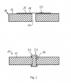
Fig. 1 depicts an embodiment of a method according to the invention; and -
Fig. 2 depcits another embodiment of a method according to the invention. - Referring to
Fig. 1 , top, afirst part 10 is provided. Thefirst part 10 is preferably aprimary structure part 12 of an aircraft (not shown). Thefirst part 10 includes at least onefirst opening 14. - A
temporary closure member 16 is attached to thefirst part 10. Thetemporary closure member 16 is anadhesive strip 18. Thetemporary closure member 16 is attached such that thefirst opening 14 is covered by thetemporary closure member 16. Thetemporary closure member 16 preferably has an easily noticeable colour, e.g. red. - The
temporary closure member 16 includes anRFID tag 20. TheRFID tag 20 is preferably integrated into thetemporary closure member 16. TheRFID tag 20 may be attached to thetemporary closure member 16 as a separate element. - After the
temporary closure member 16 is attached to thefirst part 10 and thefirst opening 14 is closed, a unique identification (unique ID) is associated with the location of the closed opening and stored on theRFID tag 20. In addition, the unique ID and/or the location of thetemporary closure member 16 are also stored in a database and included into technical drawings for subsequent manufacturing. Alternatively or additionally the frequency of theRFID tag 20 can be stored. This information may be stored as scannable information, e.g. in a QR code. - At a later stage of the manufacturing process, the
first opening 14 is to be permanently closed off. A worker uses an RFID scanner and scans for thetemporary closure member 16 based on the information stored in the database or technical drawings. The worker finds thetemporary closure member 16 and removes it. Where necessary a solvent may be used. - As depicted in
Fig. 1 , bottom, apermanent member 22 is inserted in to thefirst opening 14 and fixed therein. In this embodiment thepermanent member 22 is apermanent plug 24 that closes thefirst opening 14. - Referring to
Fig. 2 , top, afirst part 10 and asecond part 11 are provided. Thefirst part 10 is preferably aprimary structure part 12 of an aircraft (not shown). Thefirst part 10 includes at least onefirst opening 14. - The
second part 11 is preferably asecondary structure part 13 of the aircraft. Thesecond part 11 includes at least onesecond opening 15. Thesecond part 11 may be a mounting bracket, for example. - The first and
second parts second openings - A
temporary closure member 16 is inserted into the aligned pair ofopenings temporary closure member 16 is attached such that the first andsecond opening temporary closure member 16. Thetemporary closure member 16 preferably has an easily noticeable colour, e.g. red. - The
temporary closure member 16 is configured as atemporary fastener 26. Thetemporary fastener 26 comprises anactuation member 27 that actuates at least one lockingmember 28 between a locked and unlocked state. In the locked state thetemporary fastener 26 is prohibited from moving along the axial direction of the pair of alignedopenings temporary fastener 26 presses the first andsecond parts - The
temporary closure member 16 according to this embodiment also includes anRFID tag 20. TheRFID tag 20 is preferably integrated into thetemporary closure member 16. TheRFID tag 20 may be attached to thetemporary closure member 16 as a separate element. - After the
temporary closure member 16 is attached to the first andsecond parts second openings RFID tag 20. In addition, the unique ID and/or the location of thetemporary closure member 16 are also stored in a database and included into technical drawings for subsequent manufacturing. Alternatively or additionally the frequency of theRFID tag 20 can be stored. This information may be stored as scannable information, e.g. in a QR code. - At a later stage of the manufacturing process, the
first part 10 is to be permanently fixed to thesecond part 11. A worker uses an RFID scanner and scans for thetemporary closure member 16 based on the information stored in the database or technical drawings. The worker finds thetemporary closure member 16 and removes it by unlocking. Where necessary a special tool may be used. - As depicted in
Fig. 2 , bottom, apermanent member 22 is inserted in to the first andsecond openings permanent member 22 is a rivet or abolt 30 that fixes the first andsecond parts - In order to improve manufacturing of an aircraft, preferably reducing the effort of reopening holes, the invention proposes a method for temporarily closing openings in an aircraft part (10, 11) during a manufacturing process, by providing a first part (10) that has a first opening (14) and positioning a temporary closure member (16) insided that first opening (14). The temporary closing member (16) has an RFID tag (20) that has stored on it a unique identification. At a later stage in the aircraft manufacturing process a scanning device is used to scan for the RFID tag (20) based on the identification. The temporary closure member (16) is removed from the first opening (14) and subsequently replaced by a permanent member (22).
-
- 10
- first part
- 11
- second part
- 12
- primary structure part
- 13
- secondary structure part
- 14
- first opening
- 15
- second opening
- 16
- temporary closure member
- 18
- adhesive strip
- 20
- RFID tag
- 22
- permanent member
- 24
- permanent plug
- 26
- temporary fastener
- 27
- actuation member
- 28
- locking member
- 30
- bolt
Claims (8)
- A method for temporarily closing openings in a part (10, 11), preferably an aircraft part (12, 13), during a manufacturing process, the method comprising:a) providing a first part (10) having at least one first opening (14);b) positioning a temporary closure member (16) so as to close the first opening (14), the temporary closing member (16) having an RFID tag (20);c) associating a unique identification with the first opening (14) and storing the identification on the RFID tag (20);d) at a later stage, scanning for the RFID tag (20) with an RFID scanning device based on the identification and removing the temporary closure member (16) from the first opening (14) and installing a permanent member (22) in the first opening (14).
- The method according to claim 1, wherein step a) comprises providing a second part (11) having at least one second opening (15) and aligning at least one pair of first and second openings (14, 15).
- The method according to any of the preceding claims, wherein in step b) the temporary closure member (16) is configured as an adhesive strip (18) and removable attached to the first part (10) and/or second part (11) by adhesive bonding such that the first and/or second openings (14, 15) are closed, wherein the RFID tag (20) is integrated into the adhesive strip.
- The method according to any of the preceding claims, wherein in step b) the temporary closure member (16) is configured as a temporary fastener (26) that is getting inserted into the first and/or second openings (14, 15) such that the respective opening (14, 15) is closed and the first and second parts (10, 11) are removable fastened to each other by positive locking and/or friction locking.
- The method according to any of the preceding claims, wherein step c) comprises including a scannable information tag that includes information indicative of an RFID frequency and/or the unique identification of the respective RFID tag (20) into technical drawing data, and step d) comprises scanning the information tag from the technical drawings and finding the RFID tag (20) based on that information.
- The method according to any of the preceding claims, wherein step d) comprises the permanent member (22) being configured as a bolt or rivet or plug that gets permanently installed in the first and/or second opening (14, 15), preferably to fasten the second part (11) to the first part (10).
- The method according to any of the preceding claims, wherein the first part (10) is a primary structure part (12) of an aircraft and the second part (11) is a secondary structure part (13) of an aircraft.
- The method according to any of the preceding claims, wherein the first part (10) is a duct and the temporary closure member (16) is a plug that gets inserted such that the duct is temporarily closed.
Priority Applications (3)
| Application Number | Priority Date | Filing Date | Title |
|---|---|---|---|
| EP22165990.7A EP4253256B1 (en) | 2022-03-31 | 2022-03-31 | Method for temporarily closing openings in aircraft parts |
| US18/177,961 US12566425B2 (en) | 2022-03-31 | 2023-03-03 | Method for temporarily closing openings in aircraft parts |
| CN202310283951.3A CN116891004A (en) | 2022-03-31 | 2023-03-22 | Method for temporarily closing an opening in an aircraft part |
Applications Claiming Priority (1)
| Application Number | Priority Date | Filing Date | Title |
|---|---|---|---|
| EP22165990.7A EP4253256B1 (en) | 2022-03-31 | 2022-03-31 | Method for temporarily closing openings in aircraft parts |
Publications (2)
| Publication Number | Publication Date |
|---|---|
| EP4253256A1 true EP4253256A1 (en) | 2023-10-04 |
| EP4253256B1 EP4253256B1 (en) | 2025-06-04 |
Family
ID=81328328
Family Applications (1)
| Application Number | Title | Priority Date | Filing Date |
|---|---|---|---|
| EP22165990.7A Active EP4253256B1 (en) | 2022-03-31 | 2022-03-31 | Method for temporarily closing openings in aircraft parts |
Country Status (3)
| Country | Link |
|---|---|
| US (1) | US12566425B2 (en) |
| EP (1) | EP4253256B1 (en) |
| CN (1) | CN116891004A (en) |
Citations (5)
| Publication number | Priority date | Publication date | Assignee | Title |
|---|---|---|---|---|
| US8521448B1 (en) * | 2009-10-21 | 2013-08-27 | The Boeing Company | Structural analysis using measurement of fastener parameters |
| US9092714B1 (en) * | 2014-05-15 | 2015-07-28 | Northup Grumman Systems Corporation | Smart energized tapes for FOD-free aircraft applications |
| US20160243702A1 (en) * | 2015-02-25 | 2016-08-25 | The Boeing Company | Substantially Simultaneous Manufacturing Functions |
| EP3812968A1 (en) * | 2019-10-24 | 2021-04-28 | The Boeing Company | Intelligent fasteners |
| US20210206512A1 (en) * | 2020-01-03 | 2021-07-08 | The Boeing Company | Increased visibility of indicating markers in a structure and associated system and method |
Family Cites Families (1)
| Publication number | Priority date | Publication date | Assignee | Title |
|---|---|---|---|---|
| US9415411B2 (en) * | 2014-01-03 | 2016-08-16 | The Boeing Company | Masking plug |
-
2022
- 2022-03-31 EP EP22165990.7A patent/EP4253256B1/en active Active
-
2023
- 2023-03-03 US US18/177,961 patent/US12566425B2/en active Active
- 2023-03-22 CN CN202310283951.3A patent/CN116891004A/en active Pending
Patent Citations (5)
| Publication number | Priority date | Publication date | Assignee | Title |
|---|---|---|---|---|
| US8521448B1 (en) * | 2009-10-21 | 2013-08-27 | The Boeing Company | Structural analysis using measurement of fastener parameters |
| US9092714B1 (en) * | 2014-05-15 | 2015-07-28 | Northup Grumman Systems Corporation | Smart energized tapes for FOD-free aircraft applications |
| US20160243702A1 (en) * | 2015-02-25 | 2016-08-25 | The Boeing Company | Substantially Simultaneous Manufacturing Functions |
| EP3812968A1 (en) * | 2019-10-24 | 2021-04-28 | The Boeing Company | Intelligent fasteners |
| US20210206512A1 (en) * | 2020-01-03 | 2021-07-08 | The Boeing Company | Increased visibility of indicating markers in a structure and associated system and method |
Also Published As
| Publication number | Publication date |
|---|---|
| CN116891004A (en) | 2023-10-17 |
| US20230315056A1 (en) | 2023-10-05 |
| US12566425B2 (en) | 2026-03-03 |
| EP4253256B1 (en) | 2025-06-04 |
Similar Documents
| Publication | Publication Date | Title |
|---|---|---|
| ES2704474T3 (en) | Intelligent fastening system | |
| US8851789B2 (en) | Systems and methods for venting gas in the event of an explosion in a space covered by a manhole cover | |
| US9074392B2 (en) | Multi-point exit door lock and method of installation | |
| US20090055293A1 (en) | System for managing inventories comprising downhole tools used in the drilling, completion, and production of oil and gas wells | |
| CA3002611A1 (en) | Method for determining information relating to elevator components received in an elevator shaft | |
| US7270353B2 (en) | Multiple transponder seal device | |
| KR20160112969A (en) | System and method for tamper detection using rfid devices | |
| US12566425B2 (en) | Method for temporarily closing openings in aircraft parts | |
| US7118144B2 (en) | Padlock | |
| CN101425240A (en) | Intelligent fastener installation system | |
| US20180163392A1 (en) | Apparatus and method for coding of an anchor point in a structure | |
| CN106437304A (en) | Safety system | |
| US20140110474A1 (en) | Antenna deployment | |
| US6959567B2 (en) | Lid device of double-sided auxiliary lock | |
| US7160050B2 (en) | Lockable manhole cover | |
| JP6985428B2 (en) | One-sided fastening system for identification placards for utility burial chamber lids | |
| US10569344B2 (en) | Method and system for defining the position of a fastener with a peen mark | |
| US7360806B2 (en) | Methods and apparatus for facilitating security and tamper control | |
| CN110217658A (en) | The stop identifying system referred to for determining the building stop of elevator | |
| EP2284433A1 (en) | Tag for bottles, such as gas bottles and gas cylinders | |
| CN101155746B (en) | elevator door interlocking device | |
| US11834944B2 (en) | Downhole electronics puck and retention, installation and removal methods | |
| US7690091B2 (en) | Loop closure | |
| EP2709085A1 (en) | Method of certifying objects, sealing device and certifying system | |
| Campeau et al. | Artificial intelligence using real-time data |
Legal Events
| Date | Code | Title | Description |
|---|---|---|---|
| PUAI | Public reference made under article 153(3) epc to a published international application that has entered the european phase |
Free format text: ORIGINAL CODE: 0009012 |
|
| STAA | Information on the status of an ep patent application or granted ep patent |
Free format text: STATUS: THE APPLICATION HAS BEEN PUBLISHED |
|
| AK | Designated contracting states |
Kind code of ref document: A1 Designated state(s): AL AT BE BG CH CY CZ DE DK EE ES FI FR GB GR HR HU IE IS IT LI LT LU LV MC MK MT NL NO PL PT RO RS SE SI SK SM TR |
|
| STAA | Information on the status of an ep patent application or granted ep patent |
Free format text: STATUS: REQUEST FOR EXAMINATION WAS MADE |
|
| 17P | Request for examination filed |
Effective date: 20240404 |
|
| RBV | Designated contracting states (corrected) |
Designated state(s): AL AT BE BG CH CY CZ DE DK EE ES FI FR GB GR HR HU IE IS IT LI LT LU LV MC MK MT NL NO PL PT RO RS SE SI SK SM TR |
|
| GRAP | Despatch of communication of intention to grant a patent |
Free format text: ORIGINAL CODE: EPIDOSNIGR1 |
|
| STAA | Information on the status of an ep patent application or granted ep patent |
Free format text: STATUS: GRANT OF PATENT IS INTENDED |
|
| RIC1 | Information provided on ipc code assigned before grant |
Ipc: H01Q 1/22 20060101ALI20250212BHEP Ipc: G06K 19/04 20060101ALI20250212BHEP Ipc: F16B 19/10 20060101ALI20250212BHEP Ipc: B64F 5/10 20170101AFI20250212BHEP |
|
| INTG | Intention to grant announced |
Effective date: 20250221 |
|
| GRAS | Grant fee paid |
Free format text: ORIGINAL CODE: EPIDOSNIGR3 |
|
| GRAA | (expected) grant |
Free format text: ORIGINAL CODE: 0009210 |
|
| STAA | Information on the status of an ep patent application or granted ep patent |
Free format text: STATUS: THE PATENT HAS BEEN GRANTED |
|
| AK | Designated contracting states |
Kind code of ref document: B1 Designated state(s): AL AT BE BG CH CY CZ DE DK EE ES FI FR GB GR HR HU IE IS IT LI LT LU LV MC MK MT NL NO PL PT RO RS SE SI SK SM TR |
|
| REG | Reference to a national code |
Ref country code: GB Ref legal event code: FG4D |
|
| REG | Reference to a national code |
Ref country code: CH Ref legal event code: EP |
|
| REG | Reference to a national code |
Ref country code: DE Ref legal event code: R096 Ref document number: 602022015343 Country of ref document: DE |
|
| REG | Reference to a national code |
Ref country code: IE Ref legal event code: FG4D |
|
| REG | Reference to a national code |
Ref country code: NL Ref legal event code: MP Effective date: 20250604 |
|
| PG25 | Lapsed in a contracting state [announced via postgrant information from national office to epo] |
Ref country code: ES Free format text: LAPSE BECAUSE OF FAILURE TO SUBMIT A TRANSLATION OF THE DESCRIPTION OR TO PAY THE FEE WITHIN THE PRESCRIBED TIME-LIMIT Effective date: 20250604 Ref country code: FI Free format text: LAPSE BECAUSE OF FAILURE TO SUBMIT A TRANSLATION OF THE DESCRIPTION OR TO PAY THE FEE WITHIN THE PRESCRIBED TIME-LIMIT Effective date: 20250604 |
|
| REG | Reference to a national code |
Ref country code: LT Ref legal event code: MG9D |
|
| PG25 | Lapsed in a contracting state [announced via postgrant information from national office to epo] |
Ref country code: GR Free format text: LAPSE BECAUSE OF FAILURE TO SUBMIT A TRANSLATION OF THE DESCRIPTION OR TO PAY THE FEE WITHIN THE PRESCRIBED TIME-LIMIT Effective date: 20250905 Ref country code: NO Free format text: LAPSE BECAUSE OF FAILURE TO SUBMIT A TRANSLATION OF THE DESCRIPTION OR TO PAY THE FEE WITHIN THE PRESCRIBED TIME-LIMIT Effective date: 20250904 |
|
| PG25 | Lapsed in a contracting state [announced via postgrant information from national office to epo] |
Ref country code: PL Free format text: LAPSE BECAUSE OF FAILURE TO SUBMIT A TRANSLATION OF THE DESCRIPTION OR TO PAY THE FEE WITHIN THE PRESCRIBED TIME-LIMIT Effective date: 20250604 |
|
| PG25 | Lapsed in a contracting state [announced via postgrant information from national office to epo] |
Ref country code: BG Free format text: LAPSE BECAUSE OF FAILURE TO SUBMIT A TRANSLATION OF THE DESCRIPTION OR TO PAY THE FEE WITHIN THE PRESCRIBED TIME-LIMIT Effective date: 20250604 |
|
| PG25 | Lapsed in a contracting state [announced via postgrant information from national office to epo] |
Ref country code: HR Free format text: LAPSE BECAUSE OF FAILURE TO SUBMIT A TRANSLATION OF THE DESCRIPTION OR TO PAY THE FEE WITHIN THE PRESCRIBED TIME-LIMIT Effective date: 20250604 |
|
| PG25 | Lapsed in a contracting state [announced via postgrant information from national office to epo] |
Ref country code: RS Free format text: LAPSE BECAUSE OF FAILURE TO SUBMIT A TRANSLATION OF THE DESCRIPTION OR TO PAY THE FEE WITHIN THE PRESCRIBED TIME-LIMIT Effective date: 20250904 |
|
| PG25 | Lapsed in a contracting state [announced via postgrant information from national office to epo] |
Ref country code: LV Free format text: LAPSE BECAUSE OF FAILURE TO SUBMIT A TRANSLATION OF THE DESCRIPTION OR TO PAY THE FEE WITHIN THE PRESCRIBED TIME-LIMIT Effective date: 20250604 |
|
| PG25 | Lapsed in a contracting state [announced via postgrant information from national office to epo] |
Ref country code: NL Free format text: LAPSE BECAUSE OF FAILURE TO SUBMIT A TRANSLATION OF THE DESCRIPTION OR TO PAY THE FEE WITHIN THE PRESCRIBED TIME-LIMIT Effective date: 20250604 |
|
| PG25 | Lapsed in a contracting state [announced via postgrant information from national office to epo] |
Ref country code: PT Free format text: LAPSE BECAUSE OF FAILURE TO SUBMIT A TRANSLATION OF THE DESCRIPTION OR TO PAY THE FEE WITHIN THE PRESCRIBED TIME-LIMIT Effective date: 20251006 |
|
| REG | Reference to a national code |
Ref country code: AT Ref legal event code: MK05 Ref document number: 1800156 Country of ref document: AT Kind code of ref document: T Effective date: 20250604 |
|
| PG25 | Lapsed in a contracting state [announced via postgrant information from national office to epo] |
Ref country code: IS Free format text: LAPSE BECAUSE OF FAILURE TO SUBMIT A TRANSLATION OF THE DESCRIPTION OR TO PAY THE FEE WITHIN THE PRESCRIBED TIME-LIMIT Effective date: 20251004 |
|
| PG25 | Lapsed in a contracting state [announced via postgrant information from national office to epo] |
Ref country code: AT Free format text: LAPSE BECAUSE OF FAILURE TO SUBMIT A TRANSLATION OF THE DESCRIPTION OR TO PAY THE FEE WITHIN THE PRESCRIBED TIME-LIMIT Effective date: 20250604 Ref country code: SM Free format text: LAPSE BECAUSE OF FAILURE TO SUBMIT A TRANSLATION OF THE DESCRIPTION OR TO PAY THE FEE WITHIN THE PRESCRIBED TIME-LIMIT Effective date: 20250604 |
|
| PG25 | Lapsed in a contracting state [announced via postgrant information from national office to epo] |
Ref country code: CZ Free format text: LAPSE BECAUSE OF FAILURE TO SUBMIT A TRANSLATION OF THE DESCRIPTION OR TO PAY THE FEE WITHIN THE PRESCRIBED TIME-LIMIT Effective date: 20250604 |
|
| PG25 | Lapsed in a contracting state [announced via postgrant information from national office to epo] |
Ref country code: EE Free format text: LAPSE BECAUSE OF FAILURE TO SUBMIT A TRANSLATION OF THE DESCRIPTION OR TO PAY THE FEE WITHIN THE PRESCRIBED TIME-LIMIT Effective date: 20250604 |
|
| PG25 | Lapsed in a contracting state [announced via postgrant information from national office to epo] |
Ref country code: SK Free format text: LAPSE BECAUSE OF FAILURE TO SUBMIT A TRANSLATION OF THE DESCRIPTION OR TO PAY THE FEE WITHIN THE PRESCRIBED TIME-LIMIT Effective date: 20250604 |
|
| PG25 | Lapsed in a contracting state [announced via postgrant information from national office to epo] |
Ref country code: IT Free format text: LAPSE BECAUSE OF FAILURE TO SUBMIT A TRANSLATION OF THE DESCRIPTION OR TO PAY THE FEE WITHIN THE PRESCRIBED TIME-LIMIT Effective date: 20250604 |
|
| REG | Reference to a national code |
Ref country code: DE Ref legal event code: R097 Ref document number: 602022015343 Country of ref document: DE |
|
| PGFP | Annual fee paid to national office [announced via postgrant information from national office to epo] |
Ref country code: GB Payment date: 20260324 Year of fee payment: 5 |
|
| PLBE | No opposition filed within time limit |
Free format text: ORIGINAL CODE: 0009261 |
|
| STAA | Information on the status of an ep patent application or granted ep patent |
Free format text: STATUS: NO OPPOSITION FILED WITHIN TIME LIMIT |
|
| PG25 | Lapsed in a contracting state [announced via postgrant information from national office to epo] |
Ref country code: DK Free format text: LAPSE BECAUSE OF FAILURE TO SUBMIT A TRANSLATION OF THE DESCRIPTION OR TO PAY THE FEE WITHIN THE PRESCRIBED TIME-LIMIT Effective date: 20250604 |
|
| PGFP | Annual fee paid to national office [announced via postgrant information from national office to epo] |
Ref country code: DE Payment date: 20260319 Year of fee payment: 5 |
|
| REG | Reference to a national code |
Ref country code: CH Ref legal event code: L10 Free format text: ST27 STATUS EVENT CODE: U-0-0-L10-L00 (AS PROVIDED BY THE NATIONAL OFFICE) Effective date: 20260416 |
|
| PGFP | Annual fee paid to national office [announced via postgrant information from national office to epo] |
Ref country code: FR Payment date: 20260323 Year of fee payment: 5 |
|
| 26N | No opposition filed |
Effective date: 20260305 |