EP4253252A1 - An aircraft - Google Patents
An aircraft Download PDFInfo
- Publication number
- EP4253252A1 EP4253252A1 EP23163395.9A EP23163395A EP4253252A1 EP 4253252 A1 EP4253252 A1 EP 4253252A1 EP 23163395 A EP23163395 A EP 23163395A EP 4253252 A1 EP4253252 A1 EP 4253252A1
- Authority
- EP
- European Patent Office
- Prior art keywords
- aircraft
- hydrogen
- fuel
- hydrogen fuel
- port
- Prior art date
- Legal status (The legal status is an assumption and is not a legal conclusion. Google has not performed a legal analysis and makes no representation as to the accuracy of the status listed.)
- Pending
Links
Images







Classifications
-
- B—PERFORMING OPERATIONS; TRANSPORTING
- B64—AIRCRAFT; AVIATION; COSMONAUTICS
- B64D—EQUIPMENT FOR FITTING IN OR TO AIRCRAFT; FLIGHT SUITS; PARACHUTES; ARRANGEMENT OR MOUNTING OF POWER PLANTS OR PROPULSION TRANSMISSIONS IN AIRCRAFT
- B64D37/00—Arrangements in connection with fuel supply for power plant
- B64D37/30—Fuel systems for specific fuels
-
- B—PERFORMING OPERATIONS; TRANSPORTING
- B64—AIRCRAFT; AVIATION; COSMONAUTICS
- B64D—EQUIPMENT FOR FITTING IN OR TO AIRCRAFT; FLIGHT SUITS; PARACHUTES; ARRANGEMENT OR MOUNTING OF POWER PLANTS OR PROPULSION TRANSMISSIONS IN AIRCRAFT
- B64D37/00—Arrangements in connection with fuel supply for power plant
- B64D37/005—Accessories not provided for in the groups B64D37/02 - B64D37/28
-
- B—PERFORMING OPERATIONS; TRANSPORTING
- B64—AIRCRAFT; AVIATION; COSMONAUTICS
- B64D—EQUIPMENT FOR FITTING IN OR TO AIRCRAFT; FLIGHT SUITS; PARACHUTES; ARRANGEMENT OR MOUNTING OF POWER PLANTS OR PROPULSION TRANSMISSIONS IN AIRCRAFT
- B64D37/00—Arrangements in connection with fuel supply for power plant
- B64D37/02—Tanks
- B64D37/14—Filling or emptying
-
- B—PERFORMING OPERATIONS; TRANSPORTING
- B64—AIRCRAFT; AVIATION; COSMONAUTICS
- B64D—EQUIPMENT FOR FITTING IN OR TO AIRCRAFT; FLIGHT SUITS; PARACHUTES; ARRANGEMENT OR MOUNTING OF POWER PLANTS OR PROPULSION TRANSMISSIONS IN AIRCRAFT
- B64D37/00—Arrangements in connection with fuel supply for power plant
- B64D37/02—Tanks
- B64D37/14—Filling or emptying
- B64D37/16—Filling systems
-
- B—PERFORMING OPERATIONS; TRANSPORTING
- B64—AIRCRAFT; AVIATION; COSMONAUTICS
- B64D—EQUIPMENT FOR FITTING IN OR TO AIRCRAFT; FLIGHT SUITS; PARACHUTES; ARRANGEMENT OR MOUNTING OF POWER PLANTS OR PROPULSION TRANSMISSIONS IN AIRCRAFT
- B64D37/00—Arrangements in connection with fuel supply for power plant
- B64D37/32—Safety measures not otherwise provided for, e.g. preventing explosive conditions
-
- F—MECHANICAL ENGINEERING; LIGHTING; HEATING; WEAPONS; BLASTING
- F02—COMBUSTION ENGINES; HOT-GAS OR COMBUSTION-PRODUCT ENGINE PLANTS
- F02C—GAS-TURBINE PLANTS; AIR INTAKES FOR JET-PROPULSION PLANTS; CONTROLLING FUEL SUPPLY IN AIR-BREATHING JET-PROPULSION PLANTS
- F02C7/00—Features, components parts, details or accessories, not provided for in, or of interest apart form groups F02C1/00 - F02C6/00; Air intakes for jet-propulsion plants
- F02C7/22—Fuel supply systems
-
- F—MECHANICAL ENGINEERING; LIGHTING; HEATING; WEAPONS; BLASTING
- F17—STORING OR DISTRIBUTING GASES OR LIQUIDS
- F17C—VESSELS FOR CONTAINING OR STORING COMPRESSED, LIQUEFIED OR SOLIDIFIED GASES; FIXED-CAPACITY GAS-HOLDERS; FILLING VESSELS WITH, OR DISCHARGING FROM VESSELS, COMPRESSED, LIQUEFIED, OR SOLIDIFIED GASES
- F17C2205/00—Vessel construction, in particular mounting arrangements, attachments or identifications means
- F17C2205/03—Fluid connections, filters, valves, closure means or other attachments
- F17C2205/0302—Fittings, valves, filters, or components in connection with the gas storage device
- F17C2205/0352—Pipes
-
- F—MECHANICAL ENGINEERING; LIGHTING; HEATING; WEAPONS; BLASTING
- F17—STORING OR DISTRIBUTING GASES OR LIQUIDS
- F17C—VESSELS FOR CONTAINING OR STORING COMPRESSED, LIQUEFIED OR SOLIDIFIED GASES; FIXED-CAPACITY GAS-HOLDERS; FILLING VESSELS WITH, OR DISCHARGING FROM VESSELS, COMPRESSED, LIQUEFIED, OR SOLIDIFIED GASES
- F17C2205/00—Vessel construction, in particular mounting arrangements, attachments or identifications means
- F17C2205/03—Fluid connections, filters, valves, closure means or other attachments
- F17C2205/0302—Fittings, valves, filters, or components in connection with the gas storage device
- F17C2205/0352—Pipes
- F17C2205/0358—Pipes coaxial
-
- F—MECHANICAL ENGINEERING; LIGHTING; HEATING; WEAPONS; BLASTING
- F17—STORING OR DISTRIBUTING GASES OR LIQUIDS
- F17C—VESSELS FOR CONTAINING OR STORING COMPRESSED, LIQUEFIED OR SOLIDIFIED GASES; FIXED-CAPACITY GAS-HOLDERS; FILLING VESSELS WITH, OR DISCHARGING FROM VESSELS, COMPRESSED, LIQUEFIED, OR SOLIDIFIED GASES
- F17C2221/00—Handled fluid, in particular type of fluid
- F17C2221/01—Pure fluids
- F17C2221/012—Hydrogen
-
- F—MECHANICAL ENGINEERING; LIGHTING; HEATING; WEAPONS; BLASTING
- F17—STORING OR DISTRIBUTING GASES OR LIQUIDS
- F17C—VESSELS FOR CONTAINING OR STORING COMPRESSED, LIQUEFIED OR SOLIDIFIED GASES; FIXED-CAPACITY GAS-HOLDERS; FILLING VESSELS WITH, OR DISCHARGING FROM VESSELS, COMPRESSED, LIQUEFIED, OR SOLIDIFIED GASES
- F17C2265/00—Effects achieved by gas storage or gas handling
- F17C2265/06—Fluid distribution
- F17C2265/065—Fluid distribution for refuelling vehicle fuel tanks
-
- F—MECHANICAL ENGINEERING; LIGHTING; HEATING; WEAPONS; BLASTING
- F17—STORING OR DISTRIBUTING GASES OR LIQUIDS
- F17C—VESSELS FOR CONTAINING OR STORING COMPRESSED, LIQUEFIED OR SOLIDIFIED GASES; FIXED-CAPACITY GAS-HOLDERS; FILLING VESSELS WITH, OR DISCHARGING FROM VESSELS, COMPRESSED, LIQUEFIED, OR SOLIDIFIED GASES
- F17C2270/00—Applications
- F17C2270/01—Applications for fluid transport or storage
- F17C2270/0186—Applications for fluid transport or storage in the air or in space
- F17C2270/0189—Planes
Definitions
- the present invention relates to an aircraft, an aircraft refuelling port, and a method of refuelling an aircraft.
- the fuel lines are formed of multiple discrete sections of fuel pipe connected by couplings, axial compensators, and other connectors.
- the connections between these various parts are a potential source of leaks, can increase thermal ingress, and make assembly/disassembly more complex.
- a first aspect of the invention provides an aircraft comprising: a fuel tank for storing liquid hydrogen; an aircraft power plant and/or an aircraft refuelling port; and a hydrogen fuel line extending from a first end to a second end, the first end at the fuel tank and the second end at one of the aircraft power plant and the aircraft refuelling port; wherein the hydrogen fuel line is rigidly continuous and substantially unconstrained along an axial direction of the hydrogen fuel line between the first end and the second end; and wherein the first and/or second end is moveable in the axial direction of the hydrogen fuel line.
- Rigidly continuous refers to the hydrogen fuel line being uninterrupted by axial compensators, bellows, or any other means of providing significant axial displacement.
- the material from which the hydrogen fuel line is constructed may itself still offer some relative level of flexibility.
- the hydrogen fuel line may comprise two or more sections of fuel line that are rigidly connected (e.g. welded or otherwise connected), or the hydrogen fuel line may be one continuous fuel line.
- Substantially unconstrained refers to the end of the hydrogen fuel line not being fixedly attached to the aircraft or other structure. This does not preclude some constraint along the hydrogen fuel line (e.g. at the ends and/or at intermediate positions), as long as such a constraint allows at least some relative axial movement to compensate for the loads acting on the hydrogen fuel lines.
- the end of the fuel line is closer than the other end and close enough to perform its function of allowing fuel in to or out of the tank.
- the end may be directly attached to the fuel tank, aircraft power plant or refuelling port.
- the number of compensators (for compensating axial and/or angular displacements) and other connections on the fuel line may be significantly reduced, thereby reducing potential sites for leakage from the fuel line. This can be particularly beneficial in flight, or when the aircraft is moving, as the loads on the fuel lines (via deflections of the airframe) are greatest at these times.
- a second aspect of the invention provides an aircraft comprising: a fuel tank for storing liquid hydrogen; an aircraft refuelling port; and a hydrogen fuel line extending from a first end to a second end, the first end at the fuel tank and the second end at the aircraft refuelling port; wherein the hydrogen fuel line comprises a first fuel pipe configured to convey liquid hydrogen from the aircraft refuelling port to the fuel tank, and a second fuel pipe surrounding the first fuel pipe and configured to convey gases from the fuel tank to the aircraft refuelling port.
- the liquid hydrogen in the first fuel pipe is insulated by the gases in the second fuel pipe that surrounds the first fuel pipe. This may assist in maintaining a low (cryogenic) temperature that maintains the hydrogen in a liquid state, e.g. as it enters the hydrogen fuel tanks.
- the second fuel pipe may be configured to convey gaseous hydrogen from the fuel tank to the aircraft refuelling port.
- the first end may extend into the fuel tank and be moveable along the axial direction of the hydrogen fuel line.
- the second end may be moveable along the axial direction of the hydrogen fuel line.
- the second end may be at the aircraft refuelling port.
- the second end may be coupled via a flexible element that allows limited movement of the second end relative to the aircraft power plant or aircraft refuelling port.
- the hydrogen fuel line may be uninterrupted between the first end and the second end.
- the aircraft may comprise an outer pipe surrounding the hydrogen fuel line, wherein the outer pipe is fixedly coupled at a first end at the fuel tank and fixedly coupled at a second end at the aircraft power plant or the aircraft refuelling port.
- the aircraft may further comprise a vacuum between the outer pipe and the hydrogen fuel line.
- the aircraft may comprise a fuselage and a wing.
- the hydrogen fuel line may extend between the fuselage and the wing.
- the hydrogen fuel line may extend along at least 30% of a total length of the fuselage and/or at least 30% of a span of a wing.
- the aircraft power plant may be an aircraft engine or an electromotor.
- the aircraft may comprise: two or more fuel tanks; two or more hydrogen fuel lines, each hydrogen fuel line extending from a first end to a second end, each first end at a respective fuel tank and each second end at one of an aircraft power plant and the aircraft refuelling port; wherein each hydrogen fuel line is substantially unconstrained along an axial direction between the first end and the second end; and wherein the first and/or second end of each hydrogen fuel line is moveable in the axial direction of the hydrogen fuel line.
- each of the two or more hydrogen fuel lines may attach to a common coupling so as to be fixedly attached to each other.
- the common coupling may be at the aircraft refuelling port.
- a third aspect of the invention provides an aircraft refuelling port for delivering liquid hydrogen to a hydrogen fuel tank and recovering gases expelled from the hydrogen fuel tank, the refuelling port configured to attach to a hydrogen refuelling hose on a first side and attach to a hydrogen fuel line on a second side, the refuelling port comprising a first fuel port section configured to convey liquid hydrogen towards a hydrogen fuel tank, and a second fuel port section surrounding the first fuel port section and configured to convey gases away from the hydrogen fuel tank.
- a fourth aspect of the invention provides a method of refuelling an aircraft, comprising: coupling a hydrogen refuelling hose to an aircraft refuelling port, the refuelling port comprising a first fuel port section configured to convey liquid hydrogen towards a hydrogen fuel tank, and a second fuel port section surrounding the first fuel port section and configured to convey gases away from the hydrogen fuel tank; delivering liquid hydrogen fuel through the first fuel port section to a hydrogen fuel tank of the aircraft; and recovering gases expelled from the hydrogen fuel tank through the second fuel port section.
- gases expelled from the fuel tank during refuelling can be recovered and prevented from being expelled to atmosphere, for example channelled back to the refuelling tank.
- the gases can be expelled at an alternative location away from the refuelling port.
- Figure 1 shows an existing aircraft 1 with port and starboard fixed wings 2, 3, engines 9, a fuselage 4 with a nose end 5 and a tail end 6, the tail end 6 including horizontal and vertical stabilising surfaces 7, 8.
- the aircraft 1 is a typical jet passenger transonic transport aircraft but the invention is applicable to a wide variety of fixed wing aircraft types, including commercial, military, passenger, cargo, jet, propeller, general aviation, etc. with any number of engines attached to the wings or fuselage.
- Each wing 2, 3 of the aircraft 1 has a cantilevered structure with a length extending in a span-wise direction from a wing root 10 to a wing tip 11, the root 10 being joined to the aircraft fuselage 4.
- Hydrogen may be utilised as an aviation fuel in a number of ways, such as hydrogen direct burn (e.g. a modified gas turbine engine may provide power by burning hydrogen in the turbojet combustion chambers) or converting the hydrogen to electricity by using fuel cell technology in which the electrochemical cell converts the chemical energy of the hydrogen fuel and an oxidising agent (i.e. oxygen) into electricity through redox reactions.
- hydrogen direct burn e.g. a modified gas turbine engine may provide power by burning hydrogen in the turbojet combustion chambers
- converting the hydrogen to electricity by using fuel cell technology in which the electrochemical cell converts the chemical energy of the hydrogen fuel and an oxidising agent (i.e. oxygen) into electricity through redox reactions.
- an oxidising agent i.e. oxygen
- the hydrogen tank(s) 12 may be located in any suitable location on the aircraft 1, but are typically located in separate tanks below the wings 2, 3 (e.g. in fuel pods), in the wings 2, 3 or in one or more fuel tanks located within or adjacent the fuselage 4.
- Figure 2 shows a hydrogen fuel tank 12 located towards the rear of the fuselage 4, whilst Figure 3 shows the tanks located in the wings 2, 3.
- Hydrogen fuel lines 14a may extend from the fuel tank(s) 12 to the aircraft power plants (e.g. engines 9 and/or fuel cells 70) so as to channel hydrogen fuel to the power plants (these fuel lines 14a may alternatively be referred to as hydrogen distribution lines 14a).
- Hydrogen fuel lines 14b may extend from refuelling ports 16 located on an outer surface of the aircraft 1 (such as a lower cover 28 of a wing 2, 3) to the fuel tank(s) 12 (these fuel lines may be referred to as hydrogen refuelling lines 14b).
- the hydrogen fuel lines 14a, 14b may extend significant distances through the wing box structure of the wings 2, 3 and/or through or adjacent the structure of the fuselage 4.
- the hydrogen fuel lines 14a extend from the engines 9 on the wings 2, 3 to a hydrogen fuel tank 12 located in the fuselage 4
- hydrogen fuel lines 14b extend from the hydrogen fuel tank 12 to a refuelling port 16 located aft of the hydrogen fuel tank 12 in the fuselage 4.
- the hydrogen fuel lines 14a extend from the engines 9 on the wings 2, 3 to a hydrogen fuel tank 12 located on the wing 2, 3, and hydrogen fuel lines 14b extend from the hydrogen fuel tank 12 to a refuelling port 16 outboard of the hydrogen fuel tank 12. It will be understood that there are many further permutations, but that at least some of the hydrogen fuel lines 14a, 14b are required to extend significant distances across the aircraft 1.
- Typical hydrogen fuel lines 14a, 14b will be fixedly attached at connectors 21 at either end and include various pipes 22, couplings 23, bellows (e.g. axial compensators 24), as well as valves and control sensors.
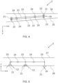
- Figures 4 & 5 show a hydrogen line 14a, 14b in the port wing 2 and extending in the spanwise direction (x-direction) between a leading edge 25 and a trailing edge 26, an upper cover 27 and a lower cover 28 of the wing 2.
- the longitudinal direction of the aircraft 1 is indicated generally as the y-direction
- the vertical axis is indicated generally as the z-direction.
- the fuel line 14a includes a connector 21 at each end, and several couplings 23 and axial compensators 24 along the length of the fuel line 14a, 14b. This can help to mitigate the effect of airframe deflections caused by aerodynamic and other external loads.
- the axial displacements of the fuel lines 14a, 14b also need to be accounted for due to the exposure of the fuel lines 14a, 14b to a wide range of operating temperatures ranging from the cryogenic temperatures of the liquid hydrogen to the potentially much higher temperatures of ambient, for which axial compensators or similar can be used.
- the connections between these various parts are a significant potential source of leaks, can increase thermal ingress, and make assembly/disassembly more complex. However, conventionally these various parts are seen as essential to ensuring the hydrogen fuel lines 14a, 14b can withstand the axial and out-of-plane deflections often encountered.
- the aircraft 1 may comprise one or more hydrogen fuel lines 114a that extend from a first end 131 to a second end 132.
- the first end 131 may be located at a fuel tank 12 and the second end 132 located at an aircraft power plant (e.g. engines 9 and/or fuel cells 70).
- the aircraft may comprise one or more hydrogen fuel lines 114b that extend from a first end 131 to a second end 132 and in which the first end 131 is located at a fuel tank 12 and the second end 132 is located at an aircraft refuelling port 16.
- the hydrogen fuel line 114a, 114b is substantially unconstrained along its axial direction between the first end 131 and the second end 132, and at least one end 131, 132 of the hydrogen fuel line 114a, 114b is moveable in the axial direction of the hydrogen fuel line 114a, 114b.
- FIGS 6 and 7 show an example in which two hydrogen fuel lines 114b extend from a respective hydrogen fuel tank 12 to a common aircraft refuelling port 16.
- the hydrogen fuel lines 114a, 114b are substantially unconstrained at the first end 131, located at each fuel tank 12, and attach to a common coupling 121 at the second end 132.
- substantially unconstrained refers to the end of the hydrogen fuel line 114b not being fixedly attached, although it may still be attached at the end 131, 132 if the constraint allows at least some relative axial movement to compensate for the loads acting on the hydrogen fuel lines 114a, 114b.
- the common connector 121 may be located at an aircraft refuelling port 16 of the aircraft 1.
- the hydrogen fuel tank 12 is substantially unconstrained at one end 131, 132, specifically the first end 131 in the present example although in other examples the second end 132 may be unconstrained in addition or alternatively, the unconstrained end 131, 132 of the hydrogen fuel line 114b is able to move axially and thereby compensate for the loads that may act on the hydrogen fuel line 114b.
- each hydrogen fuel line 114b does not include any such components and so has a single continuous fuel pipe extending from the first end 131 to the second end 132.
- Such a continuous hydrogen fuel line 114a, 114b may be referred to as being uninterrupted between the first end 131 and the second end 132.
- Figure 8 shows an example of a hydrogen fuel line 114b extending from a first end 131 to a second end 132, with the first end 131 located at a hydrogen fuel tank 12 and the second end 132 at an aircraft refuelling port 16 of the aircraft 1.
- the hydrogen fuel line 114b comprises a first fuel pipe 141 configured to convey liquid hydrogen from the aircraft refuelling port 16 to the hydrogen fuel tank 12. As the hydrogen fuel tank 12 is filled with liquid hydrogen via the first fuel pipe 141, gaseous hydrogen builds up in the hydrogen fuel tank 12. To remove this gaseous hydrogen, a second fuel pipe 142 extends from the hydrogen fuel tank 12.
- the gaseous hydrogen typically may have a temperature of around -245°C to - 250°C, in comparison to the liquid hydrogen which has a temperature below -253°C at atmospheric pressures.
- the second fuel pipe 142 may surround the first fuel pipe 141, with the second fuel pipe 142 configured to convey the gaseous hydrogen from the fuel tank 12 to the aircraft refuelling port 16.
- the refuelling port 16 may comprise a first fuel port section 17a configured to convey liquid hydrogen towards the fuel tank 12, and a second fuel port section 17b surrounding the first fuel port section 17a and configured to convey gases (such as gaseous hydrogen) away from the fuel tank 12.
- the first fuel port section 17a is arranged to couple to the first fuel pipe 141
- the second fuel port section 17b is configured to couple to the second fuel pipe 142.
- the gaseous hydrogen acts as a thermal insulator between the atmospheric temperatures around the hydrogen fuel line 114b and the liquid hydrogen in the first fuel pipe 141. This helps to maintain a low (cryogenic) temperature so as to maintain the hydrogen in a liquid state as it enters the fuel tank 12.
- the first end 143 of the first fuel pipe 141 and the first end 145 of the second fuel pipe 142 may both extend into the fuel tank 12.
- the second end 144 of the first fuel pipe 141 and the second end 146 of the second fuel pipe 142 may both extend towards the aircraft refuelling port 16.
- the second end 145 of the second fuel pipe 142 may be positioned to allow the gaseous hydrogen to escape to atmosphere.
- the first fuel pipe 141 may extend further into the fuel tank 12 than the second fuel pipe 142. This may assist the second fuel pipe 142 in conveying the gaseous hydrogen from the fuel tank 12, as the second fuel pipe 142 may be positioned above the liquid hydrogen in contact with any gaseous hydrogen, or other gases, in the fuel tank 12.
- Figures 8 and 9A show an example in which the first end 143 of the first fuel pipe 141 is located below a line 165 of the liquid hydrogen and the first end 145 of the second fuel pipe 142 is located above the line 165 of the liquid hydrogen.
- an outer pipe 150 may surround the hydrogen fuel line 114b.
- the outer pipe 150 may act as an additional insulation layer to the hydrogen fuel line 114b, as well as protect the hydrogen fuel line 114b.
- the outer pipe 150 may include couplings, multiple sections of pipe, bellows and other components that compensate for the loads that may act on the outer pipe 150.
- the outer pipe 150 may be fixedly coupled at a first end 151 proximate the fuel tank 12 and fixedly coupled at a second end 152.
- the second end 152 may be proximate the aircraft power plant (e.g. engines 9 and/or fuel cells 70) or the aircraft refuelling port 16.
- the hydrogen fuel line 114b may expel gases evacuated through the second fuel pipe 142 at the second end 132.
- the second fuel pipe 142 may include a section of pipe 142a extending away from the aircraft 1 and/or aircraft refuelling port 16 so as to redirect the gases to a location distal from the aircraft 1 and/or aircraft refuelling port 16.
- one or more guides 160 may be located adjacent the outer pipe 150 and/or the hydrogen fuel line 114a, 114b.
- the guides 160 may assist in directing the outer pipe 150 and/or the hydrogen fuel line 114a, 114b.
- the guides 160 may constrain the outer pipe 150 (or the hydrogen fuel line 114a, 114b) so that in-plane movements are restricted whilst axial movements are permitted.
- first and/or second ends 131, 132 of the hydrogen fuel lines 114a, 114b may be coupled to part of the aircraft 1, such as the aircraft refuelling port 16, with the coupling being arranged to allow at least some limited movement of that end 131, 132 of the hydrogen fuel line 114a, 114b.
- the coupling may be arranged via one or more flexible elements 170.
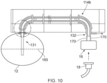
- Figure 10 shows an example in which the hydrogen fuel line 114b extends between a hydrogen fuel tank 12 and an aircraft refuelling port 16.
- the second end 132 is coupled at the aircraft refuelling port 16 via a flexible element 170 that allows limited movement of the second end 132 relative to the aircraft refuelling port 16.
- the second end 132 is moveable along the axial direction, to mitigate the effects of loads acting on the fuel line 114b, whilst the second end 132 is maintained in the locality of the aircraft refuelling port 16 so that a refuelling coupler (not shown) can be more easily connected to the second end 132 so as to fill the hydrogen fuel tank 12.
- FIG. 10 shows an example of a hydrogen fuel line 114b extending between a hydrogen fuel tank 12 and an aircraft refuelling port 16, with the second end 132 coupled at the aircraft refuelling port 16 via a flexible element 170, it will be understood that the flexible element 170 may be located at either end 131, 132 of the hydrogen fuel line 114a, 114b.
- an end 131, 132 of the hydrogen fuel line 114a, 114b may be releasably coupled at said end 131, 132, such as at the aircraft refuelling port 16.
- the end 131, 132 is selectively releasable at said end 131, 132.
- a second end 132 of the hydrogen fuel line 114a, 114b may configurable between a first configuration, in which the second end 132 is fixedly attached at the aircraft refuelling port 16, and a second configuration, in which the second end 132 is movable relative to the aircraft refuelling port 16.
- the hydrogen fuel line 114a, 114b may comprise any suitable number of pipes 141, 142, for example one, two or three pipes 141, 142.
- the pipes 141, 142 may be arranged concentrically.
- the hydrogen fuel line 114a, 114b may or may not comprise an outer pipe 150 that surrounds the hydrogen fuel line 114a, 114b.
- Figure 10 shows a refuelling coupling 18 arranged to connect to the aircraft refuelling port 16, although it will be appreciated that the refuelling coupling 18 may connect to an aircraft refuelling port 16 of any example disclosed herein.
- the refuelling coupling 18 may connect to an aircraft refuelling port 16 of any example disclosed herein.
- it is possible to recover the gases expelled from the fuel tank 12 through the second fuel port section 17b, preventing the gaseous hydrogen from releasing to atmosphere or redirecting the gases to escape to atmosphere at a different location distal from the aircraft 1 and/or aircraft refuelling port 16.
- Figure 11 shows an example in which the first fuel pipe 141 and second fuel pipe 142 are separated by spacers 145.
- An insulating material 155 is located between the second fuel pipe 142 and the outer pipe 150.
- the insulating material may be any suitable material known in the art.
- Figure 12 shows an example in which a vacuum is provided between the outer pipe 150 and the second fuel pipe 142 of the hydrogen fuel line 114a.
- spacers 145a are provided between the first fuel pipe 141 and the second fuel pipe 142
- spacers 145b are provided between the second fuel pipe 142 and the outer pipe 150.
- the outer pipe 150 may be further insulated by one or more layers of insulation material.
- the hydrogen fuel line 114a, 114b may not comprise a second fuel pipe 142 and/or an outer pipe 150.
- the hydrogen fuel line 114a, 114b may be formed so as to accommodate at least some of the various deflections and loads impacting the hydrogen fuel line 114a, 114b.
- the hydrogen fuel line 114a, 114b (the first fuel pipe 141 and/or the second fuel pipe 142 of such) may be formed of a material and/or be designed such that the hydrogen fuel line 114a, 114b is able to accommodate deflections and other forces acting on the hydrogen fuel line 114a, 114b.
- the hydrogen fuel line 114a, 114b may include a corrugated metal pipe, or include a fibre reinforced composite pipe, that allows at least some flexibility with respect to an equivalent circular cross-section metal pipe without corrugations.
- the hydrogen fuel line 114a, 114b may include a smooth inner liner (not shown) that reduces disturbances of the hydrogen fuel flowing through the fuel line 114a, 114b.
- Figure 13 shows an example in which the hydrogen fuel tank 12 is located in the fuselage 4, with a plurality of hydrogen fuel lines 114a extending from a respective first end 131 at the hydrogen fuel tank 12 to a respective second end 132 at respective aircraft engines 9 located on the wings 2, 3 (the first and second ends 131, 132 of only one of the hydrogen fuel lines 114a is shown in Figure 13 ).
- the second end 132 will be fixedly coupled at the aircraft engines 9.
- a hydrogen fuel line 114b extends from the hydrogen fuel tank 12 to an aircraft refuelling port 16 located on the fuselage 4, although it will be understood that the aircraft refuelling port 16 may be located elsewhere on the aircraft 1.
- a single hydrogen fuel line 114a, 114b extends between each power plant (e.g. engine 9) and hydrogen fuel tank 12, and between each hydrogen fuel tank 12 and aircraft refuelling port 16.
- two or more hydrogen fuel lines 114a, 114b may extend between a particular power plant and hydrogen fuel tank 12, or between a particular aircraft refuelling port 16 and hydrogen fuel tank 12.
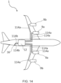
- Figure 14 shows an example in which two hydrogen fuel lines 114a extend between the hydrogen fuel tank 12 and inner engines 9a of the aircraft 1, and in which two hydrogen fuel lines 114b extend between the hydrogen fuel tank 12 and the aircraft refuelling port 16.
- Two or more hydrogen fuel lines 114a may also extend between the hydrogen fuel tank 12 and the outer engines 9b in some examples.
- These additional hydrogen fuel lines 114a, 114b provide additional paths for fuel to flow, for example in the event that one or more of the hydrogen fuel lines 114a, 114b is inoperable or otherwise inadequate.
- Figure 15 shows an example in which an aircraft 1 includes fuel cells 70 configured to power an electromotor 72, that drive one or more propellers 71.
- a hydrogen fuel line 114a extends from the hydrogen fuel tank 12 to the fuel cells 70, with the hydrogen converted to electricity by the fuel cells 70 to power (e.g.) an electromotor 72.
- the aircraft 1 may include any suitable number of fuel tanks 12.
- One or more of the fuel tanks 12 may be co-located, so as to be located directly next to one another, and/or one or more of the fuel tanks 12 may be located in different locations on the aircraft 1.
- one or more fuel tanks 12 may be located in the wings 2, 3, and one or more fuel tanks 12 may be located in the fuselage 4.
- the fuel tanks 12 may be located in separate parts of the wings 2, 3, such as towards a wing tip and towards a wing root, and may be located in separate parts of the fuselage 4, such as towards a nose end 5 and towards a tail end 6 of the fuselage 4.
- the one or more fuel tanks 12 may be mounted to an outer surface of the aircraft 1, such as mounted to a wing 2, 3.
- the engines 9 and/or fuel cells 70 are located on the wings 2,3, although it will be appreciated that the engines 9 and/or fuel cells 70 may be located on any suitable part of the aircraft, such as the fuselage 4.
Landscapes
- Engineering & Computer Science (AREA)
- Aviation & Aerospace Engineering (AREA)
- Chemical & Material Sciences (AREA)
- Combustion & Propulsion (AREA)
- Mechanical Engineering (AREA)
- General Engineering & Computer Science (AREA)
- Filling Or Discharging Of Gas Storage Vessels (AREA)
- Liquid Carbonaceous Fuels (AREA)
Abstract
Description
- The present invention relates to an aircraft, an aircraft refuelling port, and a method of refuelling an aircraft.
- There is a drive to provide aircraft that can meet future emissions targets. One approach to tackling this challenge is the use of alternative fuels, such as liquid hydrogen. A difficulty in providing aircraft that are powered by alternative fuels, such as liquid hydrogen, is the need to store the fuel in pressurised fuel tanks. These pressurised fuel tanks typically require significant amounts of space, and are therefore positioned away from the engines and other parts of the fuel system. The fuel lines may therefore extend significant distances across the aircraft, and are required to compensate for the effects of airframe deflections caused by aerodynamic and other external loads, as well as account for axial displacements due to exposure of the fuel lines to a wide range of operating temperatures ranging from the cryogenic temperatures of the liquid hydrogen to the potentially much higher temperatures of ambient atmospheric temperatures.
- As a result, the fuel lines are formed of multiple discrete sections of fuel pipe connected by couplings, axial compensators, and other connectors. The connections between these various parts are a potential source of leaks, can increase thermal ingress, and make assembly/disassembly more complex.
- A first aspect of the invention provides an aircraft comprising: a fuel tank for storing liquid hydrogen; an aircraft power plant and/or an aircraft refuelling port; and a hydrogen fuel line extending from a first end to a second end, the first end at the fuel tank and the second end at one of the aircraft power plant and the aircraft refuelling port; wherein the hydrogen fuel line is rigidly continuous and substantially unconstrained along an axial direction of the hydrogen fuel line between the first end and the second end; and wherein the first and/or second end is moveable in the axial direction of the hydrogen fuel line.
- Rigidly continuous refers to the hydrogen fuel line being uninterrupted by axial compensators, bellows, or any other means of providing significant axial displacement. The material from which the hydrogen fuel line is constructed may itself still offer some relative level of flexibility. The hydrogen fuel line may comprise two or more sections of fuel line that are rigidly connected (e.g. welded or otherwise connected), or the hydrogen fuel line may be one continuous fuel line.
- Substantially unconstrained refers to the end of the hydrogen fuel line not being fixedly attached to the aircraft or other structure. This does not preclude some constraint along the hydrogen fuel line (e.g. at the ends and/or at intermediate positions), as long as such a constraint allows at least some relative axial movement to compensate for the loads acting on the hydrogen fuel lines.
- Reference to the first end being "at" the fuel tank and the second end being "at" one of the aircraft power plant and the aircraft refuelling port, refers to that end being in the locality of said part. In other words, the end of the fuel line is closer than the other end and close enough to perform its function of allowing fuel in to or out of the tank. In some examples, the end may be directly attached to the fuel tank, aircraft power plant or refuelling port.
- With this arrangement, the number of compensators (for compensating axial and/or angular displacements) and other connections on the fuel line may be significantly reduced, thereby reducing potential sites for leakage from the fuel line. This can be particularly beneficial in flight, or when the aircraft is moving, as the loads on the fuel lines (via deflections of the airframe) are greatest at these times.
- A second aspect of the invention provides an aircraft comprising: a fuel tank for storing liquid hydrogen; an aircraft refuelling port; and a hydrogen fuel line extending from a first end to a second end, the first end at the fuel tank and the second end at the aircraft refuelling port; wherein the hydrogen fuel line comprises a first fuel pipe configured to convey liquid hydrogen from the aircraft refuelling port to the fuel tank, and a second fuel pipe surrounding the first fuel pipe and configured to convey gases from the fuel tank to the aircraft refuelling port.
- With this arrangement, the liquid hydrogen in the first fuel pipe is insulated by the gases in the second fuel pipe that surrounds the first fuel pipe. This may assist in maintaining a low (cryogenic) temperature that maintains the hydrogen in a liquid state, e.g. as it enters the hydrogen fuel tanks.
- The second fuel pipe may be configured to convey gaseous hydrogen from the fuel tank to the aircraft refuelling port.
- The first end may extend into the fuel tank and be moveable along the axial direction of the hydrogen fuel line.
- The second end may be moveable along the axial direction of the hydrogen fuel line.
- The second end may be at the aircraft refuelling port.
- The second end may be coupled via a flexible element that allows limited movement of the second end relative to the aircraft power plant or aircraft refuelling port.
- The hydrogen fuel line may be uninterrupted between the first end and the second end.
- The aircraft may comprise an outer pipe surrounding the hydrogen fuel line, wherein the outer pipe is fixedly coupled at a first end at the fuel tank and fixedly coupled at a second end at the aircraft power plant or the aircraft refuelling port.
- The aircraft may further comprise a vacuum between the outer pipe and the hydrogen fuel line.
- The aircraft may comprise a fuselage and a wing. The hydrogen fuel line may extend between the fuselage and the wing.
- The hydrogen fuel line may extend along at least 30% of a total length of the fuselage and/or at least 30% of a span of a wing.
- The aircraft power plant may be an aircraft engine or an electromotor.
- The aircraft may comprise: two or more fuel tanks; two or more hydrogen fuel lines, each hydrogen fuel line extending from a first end to a second end, each first end at a respective fuel tank and each second end at one of an aircraft power plant and the aircraft refuelling port; wherein each hydrogen fuel line is substantially unconstrained along an axial direction between the first end and the second end; and wherein the first and/or second end of each hydrogen fuel line is moveable in the axial direction of the hydrogen fuel line.
- The second end of each of the two or more hydrogen fuel lines may attach to a common coupling so as to be fixedly attached to each other.
- The common coupling may be at the aircraft refuelling port.
- A third aspect of the invention provides an aircraft refuelling port for delivering liquid hydrogen to a hydrogen fuel tank and recovering gases expelled from the hydrogen fuel tank, the refuelling port configured to attach to a hydrogen refuelling hose on a first side and attach to a hydrogen fuel line on a second side, the refuelling port comprising a first fuel port section configured to convey liquid hydrogen towards a hydrogen fuel tank, and a second fuel port section surrounding the first fuel port section and configured to convey gases away from the hydrogen fuel tank.
- A fourth aspect of the invention provides a method of refuelling an aircraft, comprising: coupling a hydrogen refuelling hose to an aircraft refuelling port, the refuelling port comprising a first fuel port section configured to convey liquid hydrogen towards a hydrogen fuel tank, and a second fuel port section surrounding the first fuel port section and configured to convey gases away from the hydrogen fuel tank; delivering liquid hydrogen fuel through the first fuel port section to a hydrogen fuel tank of the aircraft; and recovering gases expelled from the hydrogen fuel tank through the second fuel port section.
- With this arrangement, gases expelled from the fuel tank during refuelling can be recovered and prevented from being expelled to atmosphere, for example channelled back to the refuelling tank. Alternatively, the gases can be expelled at an alternative location away from the refuelling port.
- Embodiments of the invention will now be described with reference to the accompanying drawings, in which:
-
Figure 1 shows an aircraft; -
Figure 2 shows an example of a hydrogen fuel system of the aircraft; -
Figure 3 shows an example of a hydrogen fuel system of the aircraft; -
Figure 4 shows a schematic of a fuel line in a wing viewed from above the aircraft; -
Figure 5 shows a schematic of the fuel line in the wing viewed in the z-x plane; -
Figure 6 shows a schematic of an aircraft fuel system in plan view according to the present invention; -
Figure 7 shows a schematic of the aircraft fuel system ofFigure 6 viewed in the z-x plane; -
Figure 8 shows a cross-section of a fuel line extending between a refuelling port and a fuel tank; -
Figure 9A shows a cross-section of the fuel line; -
Figure 9B shows a cross-section of a refuelling port; -
Figure 10 shows a cross-section of an alternative fuel line extending between a refuelling port and a fuel tank; -
Figure 11 shows a cross-section of a first example of a fuel line; -
Figure 12 shows a cross-section of a second example of a fuel line; -
Figure 13 shows an example of an aircraft fuel system on an aircraft; -
Figure 14 shows a further example of an aircraft fuel system in which multiple fuel lines extend to the engines; -
Figure 15 shows a further example of an aircraft fuel system for a fuel cell powered aircraft. -
Figure 1 shows an existingaircraft 1 with port and starboard fixedwings engines 9, afuselage 4 with anose end 5 and atail end 6, thetail end 6 including horizontal andvertical stabilising surfaces aircraft 1 is a typical jet passenger transonic transport aircraft but the invention is applicable to a wide variety of fixed wing aircraft types, including commercial, military, passenger, cargo, jet, propeller, general aviation, etc. with any number of engines attached to the wings or fuselage. - Each
wing aircraft 1 has a cantilevered structure with a length extending in a span-wise direction from awing root 10 to awing tip 11, theroot 10 being joined to theaircraft fuselage 4. - Endeavours to increase aircraft efficiency mean that improvements to existing aircraft are continuously being made, with one such solution being the use of cryogenic fuels such as liquid hydrogen.
- Hydrogen may be utilised as an aviation fuel in a number of ways, such as hydrogen direct burn (e.g. a modified gas turbine engine may provide power by burning hydrogen in the turbojet combustion chambers) or converting the hydrogen to electricity by using fuel cell technology in which the electrochemical cell converts the chemical energy of the hydrogen fuel and an oxidising agent (i.e. oxygen) into electricity through redox reactions.
- The hydrogen tank(s) 12 may be located in any suitable location on the
aircraft 1, but are typically located in separate tanks below thewings 2, 3 (e.g. in fuel pods), in thewings fuselage 4.Figure 2 shows ahydrogen fuel tank 12 located towards the rear of thefuselage 4, whilstFigure 3 shows the tanks located in thewings -
Hydrogen fuel lines 14a may extend from the fuel tank(s) 12 to the aircraft power plants (e.g. engines 9 and/or fuel cells 70) so as to channel hydrogen fuel to the power plants (thesefuel lines 14a may alternatively be referred to ashydrogen distribution lines 14a).Hydrogen fuel lines 14b may extend from refuellingports 16 located on an outer surface of the aircraft 1 (such as alower cover 28 of awing 2, 3) to the fuel tank(s) 12 (these fuel lines may be referred to ashydrogen refuelling lines 14b). - Dependent on the respective location of the fuel tank(s) 12, power plants, and
refuelling ports 16, thehydrogen fuel lines wings fuselage 4. In the example shown inFigure 2 , thehydrogen fuel lines 14a extend from theengines 9 on thewings hydrogen fuel tank 12 located in thefuselage 4, andhydrogen fuel lines 14b extend from thehydrogen fuel tank 12 to arefuelling port 16 located aft of thehydrogen fuel tank 12 in thefuselage 4. In the example shown inFigure 3 , thehydrogen fuel lines 14a extend from theengines 9 on thewings hydrogen fuel tank 12 located on thewing hydrogen fuel lines 14b extend from thehydrogen fuel tank 12 to arefuelling port 16 outboard of thehydrogen fuel tank 12. It will be understood that there are many further permutations, but that at least some of thehydrogen fuel lines aircraft 1. - Typical
hydrogen fuel lines connectors 21 at either end and includevarious pipes 22,couplings 23, bellows (e.g. axial compensators 24), as well as valves and control sensors. For instance,Figures 4 & 5 show ahydrogen line port wing 2 and extending in the spanwise direction (x-direction) between aleading edge 25 and a trailingedge 26, anupper cover 27 and alower cover 28 of thewing 2. The longitudinal direction of theaircraft 1 is indicated generally as the y-direction, and the vertical axis is indicated generally as the z-direction. - The
fuel line 14a includes aconnector 21 at each end, andseveral couplings 23 andaxial compensators 24 along the length of thefuel line fuel lines fuel lines hydrogen fuel lines - Examples of the invention will now be described in relation to
Figures 6 to 17, in which like reference numerals are used to denote like parts with the examples ofFigures 1 to 5 , and similar reference numerals but numbered in the 100 series are used to denote similar parts. - According to an example, the
aircraft 1 may comprise one or morehydrogen fuel lines 114a that extend from afirst end 131 to asecond end 132. Thefirst end 131 may be located at afuel tank 12 and thesecond end 132 located at an aircraft power plant (e.g. engines 9 and/or fuel cells 70). Alternatively or in addition, the aircraft may comprise one or morehydrogen fuel lines 114b that extend from afirst end 131 to asecond end 132 and in which thefirst end 131 is located at afuel tank 12 and thesecond end 132 is located at anaircraft refuelling port 16. - In order to mitigate the effects of various loads imparted on the
hydrogen fuel lines hydrogen fuel line first end 131 and thesecond end 132, and at least oneend hydrogen fuel line hydrogen fuel line -
Figures 6 and 7 show an example in which twohydrogen fuel lines 114b extend from a respectivehydrogen fuel tank 12 to a commonaircraft refuelling port 16. Thehydrogen fuel lines first end 131, located at eachfuel tank 12, and attach to acommon coupling 121 at thesecond end 132. In this context, substantially unconstrained refers to the end of thehydrogen fuel line 114b not being fixedly attached, although it may still be attached at theend hydrogen fuel lines common connector 121 may be located at anaircraft refuelling port 16 of theaircraft 1. - As the
hydrogen fuel tank 12 is substantially unconstrained at oneend first end 131 in the present example although in other examples thesecond end 132 may be unconstrained in addition or alternatively, theunconstrained end hydrogen fuel line 114b is able to move axially and thereby compensate for the loads that may act on thehydrogen fuel line 114b. - These loads are typically greatest during flight and ground manoeuvres of the
aircraft 1, and so benefits of having thehydrogen fuel line hydrogen fuel line first end 131 and thesecond end 132, and having at least oneend hydrogen fuel line - As a consequence, the number of pipes, couplings, bellows and other components of the
hydrogen fuel line 114b may be reduced. In the example offigures 6 and 7 , eachhydrogen fuel line 114b does not include any such components and so has a single continuous fuel pipe extending from thefirst end 131 to thesecond end 132. Such a continuoushydrogen fuel line first end 131 and thesecond end 132. -
Figure 8 shows an example of ahydrogen fuel line 114b extending from afirst end 131 to asecond end 132, with thefirst end 131 located at ahydrogen fuel tank 12 and thesecond end 132 at anaircraft refuelling port 16 of theaircraft 1. - The
hydrogen fuel line 114b comprises afirst fuel pipe 141 configured to convey liquid hydrogen from theaircraft refuelling port 16 to thehydrogen fuel tank 12. As thehydrogen fuel tank 12 is filled with liquid hydrogen via thefirst fuel pipe 141, gaseous hydrogen builds up in thehydrogen fuel tank 12. To remove this gaseous hydrogen, asecond fuel pipe 142 extends from thehydrogen fuel tank 12. - The gaseous hydrogen typically may have a temperature of around -245°C to - 250°C, in comparison to the liquid hydrogen which has a temperature below -253°C at atmospheric pressures. As shown, for example, in
Figures 8 and 9A , thesecond fuel pipe 142 may surround thefirst fuel pipe 141, with thesecond fuel pipe 142 configured to convey the gaseous hydrogen from thefuel tank 12 to theaircraft refuelling port 16. Similarly, for example as shown inFigure 9B , therefuelling port 16 may comprise a firstfuel port section 17a configured to convey liquid hydrogen towards thefuel tank 12, and a secondfuel port section 17b surrounding the firstfuel port section 17a and configured to convey gases (such as gaseous hydrogen) away from thefuel tank 12. The firstfuel port section 17a is arranged to couple to thefirst fuel pipe 141, and the secondfuel port section 17b is configured to couple to thesecond fuel pipe 142. - As the
second fuel pipe 142 surrounds thefirst fuel pipe 141, the gaseous hydrogen acts as a thermal insulator between the atmospheric temperatures around thehydrogen fuel line 114b and the liquid hydrogen in thefirst fuel pipe 141. This helps to maintain a low (cryogenic) temperature so as to maintain the hydrogen in a liquid state as it enters thefuel tank 12. - The
first end 143 of thefirst fuel pipe 141 and thefirst end 145 of thesecond fuel pipe 142 may both extend into thefuel tank 12. Thesecond end 144 of thefirst fuel pipe 141 and thesecond end 146 of thesecond fuel pipe 142 may both extend towards theaircraft refuelling port 16. Thesecond end 145 of thesecond fuel pipe 142 may be positioned to allow the gaseous hydrogen to escape to atmosphere. - The
first fuel pipe 141 may extend further into thefuel tank 12 than thesecond fuel pipe 142. This may assist thesecond fuel pipe 142 in conveying the gaseous hydrogen from thefuel tank 12, as thesecond fuel pipe 142 may be positioned above the liquid hydrogen in contact with any gaseous hydrogen, or other gases, in thefuel tank 12.Figures 8 and 9A show an example in which thefirst end 143 of thefirst fuel pipe 141 is located below aline 165 of the liquid hydrogen and thefirst end 145 of thesecond fuel pipe 142 is located above theline 165 of the liquid hydrogen. - In some examples, an
outer pipe 150 may surround thehydrogen fuel line 114b. Theouter pipe 150 may act as an additional insulation layer to thehydrogen fuel line 114b, as well as protect thehydrogen fuel line 114b. As theouter pipe 150 is not intended to convey the hydrogen between thefirst end 131 and thesecond end 132 of thehydrogen fuel line 114b, theouter pipe 150 may include couplings, multiple sections of pipe, bellows and other components that compensate for the loads that may act on theouter pipe 150. - The
outer pipe 150 may be fixedly coupled at afirst end 151 proximate thefuel tank 12 and fixedly coupled at asecond end 152. Thesecond end 152 may be proximate the aircraft power plant (e.g. engines 9 and/or fuel cells 70) or theaircraft refuelling port 16. - The
hydrogen fuel line 114b may expel gases evacuated through thesecond fuel pipe 142 at thesecond end 132. Thesecond fuel pipe 142 may include a section ofpipe 142a extending away from theaircraft 1 and/oraircraft refuelling port 16 so as to redirect the gases to a location distal from theaircraft 1 and/oraircraft refuelling port 16. - In some examples, such as shown in
Figure 8 , one or more guides 160 (e.g. clamps or fairleads) may be located adjacent theouter pipe 150 and/or thehydrogen fuel line guides 160 may assist in directing theouter pipe 150 and/or thehydrogen fuel line guides 160 may constrain the outer pipe 150 (or thehydrogen fuel line - In some examples, the first and/or second ends 131, 132 of the
hydrogen fuel lines aircraft 1, such as theaircraft refuelling port 16, with the coupling being arranged to allow at least some limited movement of thatend hydrogen fuel line flexible elements 170. -
Figure 10 shows an example in which thehydrogen fuel line 114b extends between ahydrogen fuel tank 12 and anaircraft refuelling port 16. Thesecond end 132 is coupled at theaircraft refuelling port 16 via aflexible element 170 that allows limited movement of thesecond end 132 relative to theaircraft refuelling port 16. In this way, thesecond end 132 is moveable along the axial direction, to mitigate the effects of loads acting on thefuel line 114b, whilst thesecond end 132 is maintained in the locality of theaircraft refuelling port 16 so that a refuelling coupler (not shown) can be more easily connected to thesecond end 132 so as to fill thehydrogen fuel tank 12. - Whilst the example in
Figure 10 shows an example of ahydrogen fuel line 114b extending between ahydrogen fuel tank 12 and anaircraft refuelling port 16, with thesecond end 132 coupled at theaircraft refuelling port 16 via aflexible element 170, it will be understood that theflexible element 170 may be located at eitherend hydrogen fuel line - In some examples, an
end hydrogen fuel line end aircraft refuelling port 16. In other words, theend end second end 132 of thehydrogen fuel line second end 132 is fixedly attached at theaircraft refuelling port 16, and a second configuration, in which thesecond end 132 is movable relative to theaircraft refuelling port 16. - It will be understood that the
hydrogen fuel line pipes pipes pipes hydrogen fuel line outer pipe 150 that surrounds thehydrogen fuel line -
Figure 10 shows arefuelling coupling 18 arranged to connect to theaircraft refuelling port 16, although it will be appreciated that therefuelling coupling 18 may connect to anaircraft refuelling port 16 of any example disclosed herein. With this arrangement, it is possible to recover the gases expelled from thefuel tank 12 through the secondfuel port section 17b, preventing the gaseous hydrogen from releasing to atmosphere or redirecting the gases to escape to atmosphere at a different location distal from theaircraft 1 and/oraircraft refuelling port 16. -
Figure 11 shows an example in which thefirst fuel pipe 141 andsecond fuel pipe 142 are separated byspacers 145. An insulatingmaterial 155 is located between thesecond fuel pipe 142 and theouter pipe 150. The insulating material may be any suitable material known in the art.Figure 12 shows an example in which a vacuum is provided between theouter pipe 150 and thesecond fuel pipe 142 of thehydrogen fuel line 114a. In this example,spacers 145a are provided between thefirst fuel pipe 141 and thesecond fuel pipe 142, andspacers 145b are provided between thesecond fuel pipe 142 and theouter pipe 150. In some examples, theouter pipe 150 may be further insulated by one or more layers of insulation material. In some examples, thehydrogen fuel line second fuel pipe 142 and/or anouter pipe 150. - The
hydrogen fuel line hydrogen fuel line hydrogen fuel line first fuel pipe 141 and/or thesecond fuel pipe 142 of such) may be formed of a material and/or be designed such that thehydrogen fuel line hydrogen fuel line hydrogen fuel line hydrogen fuel line hydrogen fuel line fuel line - It will be appreciated that the examples described above are applicable to a
hydrogen fuel line first end 131 at ahydrogen fuel tank 12 to asecond end 132 at an aircraft power plant oraircraft refuelling point 16, with thehydrogen fuel tank 12, aircraft power plant andaircraft refuelling point 16 locatable in any suitable location on theaircraft 1. -
Figure 13 shows an example in which thehydrogen fuel tank 12 is located in thefuselage 4, with a plurality ofhydrogen fuel lines 114a extending from a respectivefirst end 131 at thehydrogen fuel tank 12 to a respectivesecond end 132 atrespective aircraft engines 9 located on thewings 2, 3 (the first and second ends 131, 132 of only one of thehydrogen fuel lines 114a is shown inFigure 13 ). Preferably, thesecond end 132 will be fixedly coupled at theaircraft engines 9. - In addition, a
hydrogen fuel line 114b extends from thehydrogen fuel tank 12 to anaircraft refuelling port 16 located on thefuselage 4, although it will be understood that theaircraft refuelling port 16 may be located elsewhere on theaircraft 1. - In the examples discussed above, a single
hydrogen fuel line hydrogen fuel tank 12, and between eachhydrogen fuel tank 12 andaircraft refuelling port 16. However, it will be understood that two or morehydrogen fuel lines hydrogen fuel tank 12, or between a particularaircraft refuelling port 16 andhydrogen fuel tank 12.Figure 14 shows an example in which twohydrogen fuel lines 114a extend between thehydrogen fuel tank 12 andinner engines 9a of theaircraft 1, and in which twohydrogen fuel lines 114b extend between thehydrogen fuel tank 12 and theaircraft refuelling port 16. Two or morehydrogen fuel lines 114a may also extend between thehydrogen fuel tank 12 and theouter engines 9b in some examples. These additionalhydrogen fuel lines hydrogen fuel lines - Whilst the examples above show an
aircraft 1 that includeshydrogen fuel lines hydrogen fuel lines fuel cells 70. -
Figure 15 shows an example in which anaircraft 1 includesfuel cells 70 configured to power anelectromotor 72, that drive one ormore propellers 71. Ahydrogen fuel line 114a extends from thehydrogen fuel tank 12 to thefuel cells 70, with the hydrogen converted to electricity by thefuel cells 70 to power (e.g.) anelectromotor 72. - The examples described above reference an
aircraft 1 including onefuel tank 12, although it will be appreciated that theaircraft 1 may include any suitable number offuel tanks 12. One or more of thefuel tanks 12 may be co-located, so as to be located directly next to one another, and/or one or more of thefuel tanks 12 may be located in different locations on theaircraft 1. For example, one ormore fuel tanks 12 may be located in thewings more fuel tanks 12 may be located in thefuselage 4. Thefuel tanks 12 may be located in separate parts of thewings fuselage 4, such as towards anose end 5 and towards atail end 6 of thefuselage 4. The one ormore fuel tanks 12 may be mounted to an outer surface of theaircraft 1, such as mounted to awing - The examples described above refer to the
engines 9 and/orfuel cells 70 as being located on thewings engines 9 and/orfuel cells 70 may be located on any suitable part of the aircraft, such as thefuselage 4. - Where the word 'or' appears this is to be construed to mean 'and/or' such that items referred to are not necessarily mutually exclusive and may be used in any appropriate combination.
- Although the invention has been described above with reference to one or more preferred embodiments, it will be appreciated that various changes or modifications may be made without departing from the scope of the invention as defined in the appended claims.
Claims (15)
- An aircraft comprising:a fuel tank for storing liquid hydrogen;an aircraft power plant and/or an aircraft refuelling port; anda hydrogen fuel line extending from a first end to a second end, the first end at the fuel tank and the second end at one of the aircraft power plant and the aircraft refuelling port;wherein the hydrogen fuel line is rigidly continuous and substantially unconstrained along an axial direction of the hydrogen fuel line between the first end and the second end; and wherein the first and/or second end is moveable in the axial direction of the hydrogen fuel line.
- An aircraft comprising:a fuel tank for storing liquid hydrogen; an aircraft refuelling port; and a hydrogen fuel line extending from a first end to a second end, the first end at the fuel tank and the second end at the aircraft refuelling port;wherein the hydrogen fuel line comprises a first fuel pipe configured to convey liquid hydrogen from the aircraft refuelling port to the fuel tank, and a second fuel pipe surrounding the first fuel pipe and configured to convey gases from the fuel tank to the aircraft refuelling port, preferably wherein the gas is gaseous hydrogen.
- The aircraft of any preceding claim, wherein the first end extends into the fuel tank and is moveable along the axial direction of the hydrogen fuel line.
- The aircraft of any preceding claim, wherein the second end is moveable along the axial direction of the hydrogen fuel line.
- The aircraft of claim 4, wherein the second end is at the aircraft refuelling port.
- The aircraft of claim 4 or 5, wherein the second end is coupled via a flexible element that allows limited movement of the second end relative to the aircraft power plant or aircraft refuelling port.
- The aircraft of any preceding claim, wherein the hydrogen fuel line is uninterrupted between the first end and the second end.
- The aircraft of any preceding claim, comprising an outer pipe surrounding the hydrogen fuel line, wherein the outer pipe is fixedly coupled at a first end at the fuel tank and fixedly coupled at a second end at the aircraft power plant or the aircraft refuelling port, optionally the aircraft further comprising a vacuum between the outer pipe and the hydrogen fuel line.
- The aircraft of any preceding claim, comprising a fuselage and a wing, and wherein the hydrogen fuel line extends between the fuselage and the wing.
- The aircraft of any preceding claim, wherein the hydrogen fuel line extends along at least 30% of a total length of the fuselage and/or at least 30% of a span of a wing.
- The aircraft of any preceding claim, wherein the aircraft power plant is an aircraft engine or an electromotor.
- The aircraft of any preceding claim, comprising:two or more fuel tanks;two or more hydrogen fuel lines, each hydrogen fuel line extending from a first end to a second end, each first end at a respective fuel tank and each second end at one of an aircraft power plant and the aircraft refuelling port;wherein each hydrogen fuel line is substantially unconstrained along an axial direction between the first end and the second end; and wherein the first and/or second end of each hydrogen fuel line is moveable in the axial direction of the hydrogen fuel line.
- The aircraft of claim 12, wherein the second end of each of the two or more hydrogen fuel lines attach to a common coupling so as to be fixedly attached to each other, optionally wherein the common coupling is at the aircraft refuelling port.
- An aircraft refuelling port for delivering liquid hydrogen to a hydrogen fuel tank and recovering gases expelled from the hydrogen fuel tank, the refuelling port configured to attach to a hydrogen refuelling hose on a first side and attach to a hydrogen fuel line on a second side,
the refuelling port comprising a first fuel port section configured to convey liquid hydrogen towards a hydrogen fuel tank, and a second fuel port section surrounding the first fuel port section and configured to convey gases away from the hydrogen fuel tank. - A method of refuelling an aircraft, comprising:coupling a hydrogen refuelling hose to an aircraft refuelling port, the refuelling port comprising a first fuel port section configured to convey liquid hydrogen towards a hydrogen fuel tank, and a second fuel port section surrounding the first fuel port section and configured to convey gases away from the hydrogen fuel tank;delivering liquid hydrogen fuel through the first fuel port section to a hydrogen fuel tank of the aircraft; andrecovering gases expelled from the hydrogen fuel tank through the second fuel port section.
Applications Claiming Priority (1)
| Application Number | Priority Date | Filing Date | Title |
|---|---|---|---|
| GB2204463.0A GB2617108A (en) | 2022-03-29 | 2022-03-29 | An aircraft |
Publications (1)
| Publication Number | Publication Date |
|---|---|
| EP4253252A1 true EP4253252A1 (en) | 2023-10-04 |
Family
ID=81449253
Family Applications (1)
| Application Number | Title | Priority Date | Filing Date |
|---|---|---|---|
| EP23163395.9A Pending EP4253252A1 (en) | 2022-03-29 | 2023-03-22 | An aircraft |
Country Status (4)
| Country | Link |
|---|---|
| US (1) | US12296974B2 (en) |
| EP (1) | EP4253252A1 (en) |
| CN (1) | CN116891000A (en) |
| GB (1) | GB2617108A (en) |
Cited By (2)
| Publication number | Priority date | Publication date | Assignee | Title |
|---|---|---|---|---|
| WO2026008993A1 (en) * | 2024-07-04 | 2026-01-08 | Gkn Aerospace Services Limited | Conduit for transporting at least of cryogenic material and electrical current |
| EP4438494B1 (en) * | 2023-03-31 | 2026-04-01 | Airbus Operations Limited | Aircraft connector for fluid transfer |
Families Citing this family (1)
| Publication number | Priority date | Publication date | Assignee | Title |
|---|---|---|---|---|
| EP4647344A1 (en) * | 2024-05-06 | 2025-11-12 | AIRBUS Operations GmbH | A pipe arrangement for a vehicle, such as an aircraft, propulsion system and vehicle equipped therewith |
Citations (9)
| Publication number | Priority date | Publication date | Assignee | Title |
|---|---|---|---|---|
| US20080197137A1 (en) * | 2007-02-16 | 2008-08-21 | Harald Schlag | Cryogenic storage tank with thermal shield |
| US20100122747A1 (en) * | 2007-09-10 | 2010-05-20 | Hydrogen Discoveries, Inc. | Composite Structures for Hydrogen Storage and Transfer |
| US20120104172A1 (en) * | 2010-11-02 | 2012-05-03 | Eads Deutschland Gmbh | Fuel Line in an Aircraft |
| US20160356403A1 (en) * | 2015-06-08 | 2016-12-08 | The Boeing Company | Electromagnetic effects-sensitive pass-through mounting assemblies with adjustable offset |
| CN207712306U (en) * | 2017-12-26 | 2018-08-10 | 中国空气动力研究与发展中心高速空气动力研究所 | A kind of hydrogen fuel aircraft |
| US20200072391A1 (en) * | 2018-09-05 | 2020-03-05 | Airbus Operations Limited | Pipe support |
| US20210107674A1 (en) * | 2016-05-29 | 2021-04-15 | Neoex Systems, Inc. | System and method for the transfer of cryogenic fluids |
| EP4141310A1 (en) * | 2021-08-27 | 2023-03-01 | Airbus Operations Limited | A fluid pipe connection |
| EP4180706A1 (en) * | 2021-11-10 | 2023-05-17 | Zero Emissions Aerospace Limited | Cryogenic tank |
Family Cites Families (19)
| Publication number | Priority date | Publication date | Assignee | Title |
|---|---|---|---|---|
| DE4342207C1 (en) * | 1993-12-10 | 1995-02-16 | Deutsche Aerospace | Cryosystem |
| DE502006008159D1 (en) | 2005-03-24 | 2010-12-09 | Ems Chemie Ag | Use of a piping system for volatile fluids |
| DE102011010385A1 (en) | 2011-02-05 | 2012-08-09 | Eads Deutschland Gmbh | Double-walled pipe and manufacturing process |
| FR2977299B1 (en) * | 2011-07-01 | 2014-11-07 | Airbus Operations Sas | DOUBLE SKIN TUBING SYSTEM, JOINT SYSTEM BETWEEN TWO TUBE PORTIONS, AND AIRCRAFT PROVIDED WITH SUCH A SYSTEM |
| FR2981141A1 (en) | 2011-10-07 | 2013-04-12 | Dassault Aviat | CONDUIT OF TRANSPORT OF A DOUBLE-WALL FLUID, INSTALLATION OF SUCH A DRIVING AND AIRCRAFT COMPRISING SUCH A CONDUCT |
| US8893748B2 (en) | 2012-11-08 | 2014-11-25 | Linde Aktiengesellschaft | Pipeline for high pressure cryogenic applications |
| DE102012222020B4 (en) | 2012-11-30 | 2022-03-31 | Airbus Operations Gmbh | System for supplying inert gas to an aircraft, method for supplying inert gas to an aircraft, use of a membrane and aircraft |
| US9310023B2 (en) | 2013-06-20 | 2016-04-12 | The Boeing Company | Methods and systems for distributing inert gas in an aircraft |
| DE102013107324A1 (en) | 2013-07-10 | 2015-01-15 | Airbus Operations Gmbh | Management system for an aircraft and aircraft with a pipeline system |
| DE102014107316A1 (en) * | 2014-05-23 | 2015-11-26 | Airbus Operations Gmbh | Tank system for the cryogenic storage of hydrogen and aircraft with a tank system for the cryogenic storage of hydrogen |
| JP6577192B2 (en) | 2014-05-27 | 2019-09-18 | ザ・ボーイング・カンパニーThe Boeing Company | Method of manufacturing a fluid distribution system assembly |
| FR3026091B1 (en) * | 2014-09-24 | 2023-10-06 | Zodiac Aerotechnics | METHOD AND SYSTEM FOR CIRCULATING FUEL IN AN AIRCRAFT |
| US9933093B2 (en) * | 2014-11-28 | 2018-04-03 | Embraer S.A. | Aircraft fuel line couplings in compliance with survivable crash and lightning strike requirements |
| EP3086011B1 (en) | 2015-04-21 | 2019-07-31 | Airbus Operations GmbH | Double-walled pipe with integrated heating capability for an aircraft or spacecraft |
| JP2017165242A (en) * | 2016-03-16 | 2017-09-21 | 三菱航空機株式会社 | Fuel pipe of aircraft and aircraft |
| US10794522B2 (en) | 2018-04-05 | 2020-10-06 | The Boeing Company | Flexible double walled hose connection |
| FR3120603A1 (en) * | 2021-03-11 | 2022-09-16 | Airbus Operations (S.A.S.) | Aircraft mast comprising a tubular primary structure incorporating at least one double-skin pipe and aircraft comprising at least one such mast |
| US11578638B2 (en) * | 2021-03-16 | 2023-02-14 | Marathon Petroleum Company Lp | Scalable greenhouse gas capture systems and methods |
| FR3127203A1 (en) * | 2021-09-22 | 2023-03-24 | Airbus | AIRCRAFT COMPRISING A DIHYDROGEN TRANSPORT PIPE AND A BURIAL CHANNEL FOR SAID TRANSPORT PIPE |
-
2022
- 2022-03-29 GB GB2204463.0A patent/GB2617108A/en active Pending
-
2023
- 2023-03-22 EP EP23163395.9A patent/EP4253252A1/en active Pending
- 2023-03-28 US US18/127,485 patent/US12296974B2/en active Active
- 2023-03-29 CN CN202310321286.2A patent/CN116891000A/en active Pending
Patent Citations (9)
| Publication number | Priority date | Publication date | Assignee | Title |
|---|---|---|---|---|
| US20080197137A1 (en) * | 2007-02-16 | 2008-08-21 | Harald Schlag | Cryogenic storage tank with thermal shield |
| US20100122747A1 (en) * | 2007-09-10 | 2010-05-20 | Hydrogen Discoveries, Inc. | Composite Structures for Hydrogen Storage and Transfer |
| US20120104172A1 (en) * | 2010-11-02 | 2012-05-03 | Eads Deutschland Gmbh | Fuel Line in an Aircraft |
| US20160356403A1 (en) * | 2015-06-08 | 2016-12-08 | The Boeing Company | Electromagnetic effects-sensitive pass-through mounting assemblies with adjustable offset |
| US20210107674A1 (en) * | 2016-05-29 | 2021-04-15 | Neoex Systems, Inc. | System and method for the transfer of cryogenic fluids |
| CN207712306U (en) * | 2017-12-26 | 2018-08-10 | 中国空气动力研究与发展中心高速空气动力研究所 | A kind of hydrogen fuel aircraft |
| US20200072391A1 (en) * | 2018-09-05 | 2020-03-05 | Airbus Operations Limited | Pipe support |
| EP4141310A1 (en) * | 2021-08-27 | 2023-03-01 | Airbus Operations Limited | A fluid pipe connection |
| EP4180706A1 (en) * | 2021-11-10 | 2023-05-17 | Zero Emissions Aerospace Limited | Cryogenic tank |
Cited By (2)
| Publication number | Priority date | Publication date | Assignee | Title |
|---|---|---|---|---|
| EP4438494B1 (en) * | 2023-03-31 | 2026-04-01 | Airbus Operations Limited | Aircraft connector for fluid transfer |
| WO2026008993A1 (en) * | 2024-07-04 | 2026-01-08 | Gkn Aerospace Services Limited | Conduit for transporting at least of cryogenic material and electrical current |
Also Published As
| Publication number | Publication date |
|---|---|
| GB202204463D0 (en) | 2022-05-11 |
| US20230406527A1 (en) | 2023-12-21 |
| CN116891000A (en) | 2023-10-17 |
| GB2617108A (en) | 2023-10-04 |
| US12296974B2 (en) | 2025-05-13 |
Similar Documents
| Publication | Publication Date | Title |
|---|---|---|
| EP4253252A1 (en) | An aircraft | |
| US12240622B2 (en) | Aircraft assembly | |
| US8220739B2 (en) | Beam mounted rear propulsion system for an aircraft and aircraft with such system | |
| EP4470924B1 (en) | Aircraft with hydrogen storage tanks | |
| US8844862B2 (en) | Aft pylon fairing for aircraft engine suspension system, comprising a heat shield capable of expanding freely | |
| EP4375196B1 (en) | Aircraft pipework assembly | |
| US9868543B2 (en) | Assembly for an aircraft comprising an attachment pylon primary structure formed with three independent elements | |
| US11254437B2 (en) | Aircraft engine assembly | |
| CN107654296B (en) | Thermal insulating blanket and thermal insulating blanket assembly | |
| US20250368348A1 (en) | An aircraft assembly | |
| EP4141310B1 (en) | FLUID PIPE CONNECTION | |
| EP4045869B1 (en) | Actively-cooled heat shield system and vehicle including the same | |
| EP4375195B1 (en) | AIRCRAFT DEVICE | |
| US20260116558A1 (en) | Aircraft propulsion unit comprising a main link for an engine mount, in addition to two safety links in parallel, which are connected to a front transverse reinforcement of a primary structure of a pylon | |
| US20240174373A1 (en) | Pipe spacer | |
| EP3907137B1 (en) | Propulsion system, aircraft having a propulsion system, and method of manufacturing an aircraft | |
| CN106314807A (en) | Thrust frame structure of air-breathing scramjet engine | |
| US20250223924A1 (en) | Cryogenic fuelled aircraft propulsion system | |
| WO2025116977A9 (en) | Aerodynamic hydrogen tanks, and cryogenic insulated pipes | |
| CN117360766A (en) | Wing for an aircraft and aircraft |
Legal Events
| Date | Code | Title | Description |
|---|---|---|---|
| PUAI | Public reference made under article 153(3) epc to a published international application that has entered the european phase |
Free format text: ORIGINAL CODE: 0009012 |
|
| STAA | Information on the status of an ep patent application or granted ep patent |
Free format text: STATUS: THE APPLICATION HAS BEEN PUBLISHED |
|
| AK | Designated contracting states |
Kind code of ref document: A1 Designated state(s): AL AT BE BG CH CY CZ DE DK EE ES FI FR GB GR HR HU IE IS IT LI LT LU LV MC ME MK MT NL NO PL PT RO RS SE SI SK SM TR |
|
| STAA | Information on the status of an ep patent application or granted ep patent |
Free format text: STATUS: REQUEST FOR EXAMINATION WAS MADE |
|
| 17P | Request for examination filed |
Effective date: 20240208 |
|
| RBV | Designated contracting states (corrected) |
Designated state(s): AL AT BE BG CH CY CZ DE DK EE ES FI FR GB GR HR HU IE IS IT LI LT LU LV MC ME MK MT NL NO PL PT RO RS SE SI SK SM TR |
|
| STAA | Information on the status of an ep patent application or granted ep patent |
Free format text: STATUS: EXAMINATION IS IN PROGRESS |
|
| 17Q | First examination report despatched |
Effective date: 20241002 |