EP4253221A1 - System for and method of controlling watercraft - Google Patents
System for and method of controlling watercraft Download PDFInfo
- Publication number
- EP4253221A1 EP4253221A1 EP22209848.5A EP22209848A EP4253221A1 EP 4253221 A1 EP4253221 A1 EP 4253221A1 EP 22209848 A EP22209848 A EP 22209848A EP 4253221 A1 EP4253221 A1 EP 4253221A1
- Authority
- EP
- European Patent Office
- Prior art keywords
- watercraft
- trouble
- information
- marine propulsion
- propulsion device
- Prior art date
- Legal status (The legal status is an assumption and is not a legal conclusion. Google has not performed a legal analysis and makes no representation as to the accuracy of the status listed.)
- Pending
Links
Images




Classifications
-
- B—PERFORMING OPERATIONS; TRANSPORTING
- B63—SHIPS OR OTHER WATERBORNE VESSELS; RELATED EQUIPMENT
- B63H—MARINE PROPULSION OR STEERING
- B63H20/00—Outboard propulsion units, e.g. outboard motors or Z-drives; Arrangements thereof on vessels
- B63H20/08—Means enabling movement of the position of the propulsion element, e.g. for trim, tilt or steering; Control of trim or tilt
- B63H20/12—Means enabling steering
-
- B—PERFORMING OPERATIONS; TRANSPORTING
- B63—SHIPS OR OTHER WATERBORNE VESSELS; RELATED EQUIPMENT
- B63B—SHIPS OR OTHER WATERBORNE VESSELS; EQUIPMENT FOR SHIPPING
- B63B79/00—Monitoring properties or operating parameters of vessels in operation
- B63B79/10—Monitoring properties or operating parameters of vessels in operation using sensors, e.g. pressure sensors, strain gauges or accelerometers
-
- B—PERFORMING OPERATIONS; TRANSPORTING
- B63—SHIPS OR OTHER WATERBORNE VESSELS; RELATED EQUIPMENT
- B63B—SHIPS OR OTHER WATERBORNE VESSELS; EQUIPMENT FOR SHIPPING
- B63B79/00—Monitoring properties or operating parameters of vessels in operation
- B63B79/10—Monitoring properties or operating parameters of vessels in operation using sensors, e.g. pressure sensors, strain gauges or accelerometers
- B63B79/15—Monitoring properties or operating parameters of vessels in operation using sensors, e.g. pressure sensors, strain gauges or accelerometers for monitoring environmental variables, e.g. wave height or weather data
-
- B—PERFORMING OPERATIONS; TRANSPORTING
- B63—SHIPS OR OTHER WATERBORNE VESSELS; RELATED EQUIPMENT
- B63B—SHIPS OR OTHER WATERBORNE VESSELS; EQUIPMENT FOR SHIPPING
- B63B79/00—Monitoring properties or operating parameters of vessels in operation
- B63B79/30—Monitoring properties or operating parameters of vessels in operation for diagnosing, testing or predicting the integrity or performance of vessels
-
- B—PERFORMING OPERATIONS; TRANSPORTING
- B63—SHIPS OR OTHER WATERBORNE VESSELS; RELATED EQUIPMENT
- B63H—MARINE PROPULSION OR STEERING
- B63H20/00—Outboard propulsion units, e.g. outboard motors or Z-drives; Arrangements thereof on vessels
- B63H2020/003—Arrangements of two, or more outboard propulsion units
-
- B—PERFORMING OPERATIONS; TRANSPORTING
- B63—SHIPS OR OTHER WATERBORNE VESSELS; RELATED EQUIPMENT
- B63H—MARINE PROPULSION OR STEERING
- B63H25/00—Steering; Slowing-down otherwise than by use of propulsive elements; Dynamic anchoring, i.e. positioning vessels by means of main or auxiliary propulsive elements
- B63H25/02—Initiating means for steering, for slowing down, otherwise than by use of propulsive elements, or for dynamic anchoring
- B63H2025/026—Initiating means for steering, for slowing down, otherwise than by use of propulsive elements, or for dynamic anchoring using multi-axis control levers, or the like, e.g. joysticks, wherein at least one degree of freedom is employed for steering, slowing down, or dynamic anchoring
-
- B—PERFORMING OPERATIONS; TRANSPORTING
- B63—SHIPS OR OTHER WATERBORNE VESSELS; RELATED EQUIPMENT
- B63H—MARINE PROPULSION OR STEERING
- B63H25/00—Steering; Slowing-down otherwise than by use of propulsive elements; Dynamic anchoring, i.e. positioning vessels by means of main or auxiliary propulsive elements
- B63H25/02—Initiating means for steering, for slowing down, otherwise than by use of propulsive elements, or for dynamic anchoring
- B63H25/04—Initiating means for steering, for slowing down, otherwise than by use of propulsive elements, or for dynamic anchoring automatic, e.g. reacting to compass
- B63H2025/045—Initiating means for steering, for slowing down, otherwise than by use of propulsive elements, or for dynamic anchoring automatic, e.g. reacting to compass making use of satellite radio beacon positioning systems, e.g. the Global Positioning System [GPS]
-
- B—PERFORMING OPERATIONS; TRANSPORTING
- B63—SHIPS OR OTHER WATERBORNE VESSELS; RELATED EQUIPMENT
- B63H—MARINE PROPULSION OR STEERING
- B63H25/00—Steering; Slowing-down otherwise than by use of propulsive elements; Dynamic anchoring, i.e. positioning vessels by means of main or auxiliary propulsive elements
- B63H25/42—Steering or dynamic anchoring by propulsive elements; Steering or dynamic anchoring by propellers used therefor only; Steering or dynamic anchoring by rudders carrying propellers
Definitions
- the present invention relates to a system for and a method of controlling a watercraft.
- a type of system for controlling a watercraft has an automatic control function.
- the system automatically controls a marine propulsion device attached to the watercraft.
- a system for controlling a watercraft described in JP 2020-168921 A has a position keeping function.
- the system controls a marine propulsion device such that the watercraft is kept in a predetermined position.
- the aforementioned system for controlling a watercraft includes an operating member to be operated by a user.
- the operating member includes a shift lever, a steering wheel, and/or a joystick.
- the user operates the shift lever to perform switching between a forward moving action and a rearward moving action by the marine propulsion device.
- the user operates the steering wheel to turn the watercraft.
- the user operates the joystick to move the watercraft forward, rearward, rightward, and leftward.
- the maritime environment is greater in diversity than the onshore environment. Because of this, it is not easy to grasp the following information at the sea: in what kind of environment the automatic control function is used by the user; what kind of automatic control function is used by the user; and in what kind of operational pattern the operating member is operated by the user.
- the information described herein makes it possible to grasp how the marine propulsion device is used by the user; hence, the information can be useful for enhancement in user convenience.
- a system relates to a system for controlling a watercraft including a marine propulsion device.
- the system includes a data communication module, a position sensor, and a controller.
- the data communication module performs wireless communication with an external computer.
- the position sensor detects a position of the watercraft.
- the controller obtains the position of the watercraft.
- the controller sends at least one of functional information, trouble information, and operational information to the external computer through the data communication module.
- the functional information an automatic control function used for the marine propulsion device and the position of the watercraft when the automatic control function is used are associated with each other.
- trouble information a trouble occurred in the marine propulsion device and the position of the watercraft when the trouble is occurred are associated with each other.
- an operational pattern performed by a user for the marine propulsion device and the position of the watercraft when the operational pattern is performed are associated with each other.
- a method according to another aspect of the present invention relates to a method of controlling a watercraft including a marine propulsion device.
- the method according to the present aspect includes the following: obtaining a position of the watercraft; and sending at least one of functional information, trouble information, and operational information to an external computer.
- functional information an automatic control function used for the marine propulsion device and the position of the watercraft when the automatic control function is used are associated with each other.
- trouble information a trouble occurred in the marine propulsion device and the position of the watercraft when the trouble is occurred are associated with each other.
- an operational pattern performed by a user for the marine propulsion device and the position of the watercraft when the operational pattern is performed are associated with each other.
- At least one of the functional information, the trouble information, and the operational information is sent to the external computer.
- the functional information the used automatic control function and the position of the watercraft obtained in the use of the automatic control function are associated with each other.
- the trouble information the occurred trouble and the position of the watercraft obtained in the occurrence of the trouble are associated with each other.
- the operational information the operational pattern and the position of the watercraft obtained in the performance of the operational pattern are associated with each other. Therefore, at least one of the functional information, the trouble information, and the operational information is collected by the external computer, whereby user convenience can be enhanced.
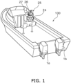
- FIG. 1 is a perspective view of a watercraft 100 to which marine propulsion devices 1a and 1b according to the embodiment are mounted.
- the marine propulsion devices 1a and 1b are mounted to the watercraft 100 as a plurality of marine propulsion devices.
- the marine propulsion devices 1a and 1b are outboard motors.
- the marine propulsion devices 1a and 1b are attached to the stern of the watercraft 100.
- the marine propulsion devices 1a and 1b are disposed in alignment in the width direction of the watercraft 100.
- the marine propulsion device 1a is disposed on the port side of the watercraft 100.
- the marine propulsion device 1b is disposed on the starboard side of the watercraft 100.
- Each marine propulsion device 1a, 1b generates a thrust for propelling the watercraft 100.
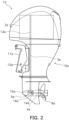
- FIG. 2 is a side view of the marine propulsion device 1a.
- the structure of the marine propulsion device 1a will be hereinafter explained; however, the structure of the marine propulsion device 1a is also true of the marine propulsion device 1b.
- the marine propulsion device 1a is attached to the watercraft 100 through a bracket 11a.
- the bracket 11a supports the marine propulsion device 1a such that the marine propulsion device 1a is rotatable about a steering shaft 12a.
- the steering shaft 12a extends in the up-and-down direction of the marine propulsion device 1a.
- the marine propulsion device 1a includes a drive source 2a, a drive shaft 3a, a propeller shaft 4a, a shift mechanism 5a, and a housing 10a.
- the drive source 2a generates the thrust for propelling the watercraft 100.
- the drive source 2a is an internal combustion engine.
- the drive source 2a includes a crankshaft 13a. The crankshaft 13a extends in the up-and-down direction of the marine propulsion device 1a.
- the drive shaft 3a is connected to the crankshaft 13a.
- the drive shaft 3a extends in the up-and-down direction of the marine propulsion device 1a.
- the propeller shaft 4a extends in the back-and-forth direction of the marine propulsion device 1a.
- the propeller shaft 4a is connected to the drive shaft 3a through the shift mechanism 5a.
- a propeller 6a is attached to the propeller shaft 4a.
- the shift mechanism 5a includes a forward moving gear 14a, a rearward moving gear 15a, and a dog clutch 16a.
- the shift mechanism 5a When gear engagement of each gear 14a, 15a is switched by the dog clutch 16a, the shift mechanism 5a is switched among a forward moving state, a rearward moving state, and a neutral state.
- the shift mechanism 5a When set in the forward moving state, the shift mechanism 5a transmits rotation, directed to move the watercraft 100 forward, from the drive shaft 3a to the propeller shaft 4a.
- the shift mechanism 5a When set in the rearward moving state, the shift mechanism 5a transmits rotation, directed to move the watercraft 100 rearward, from the drive shaft 3a to the propeller shaft 4a.
- the shift mechanism 5a When set in the neutral state, the shift mechanism 5a does not transmit rotation from the drive shaft 3a to the propeller shaft 4a.
- the housing 10a accommodates the drive source 2a, the drive shaft 3a, the propeller shaft 4a, and the shift mechanism 5a.
- FIG. 3 is a schematic diagram for showing a configuration of a control system 20 for the watercraft 100.
- the marine propulsion device 1a includes a shift actuator 7a and a steering actuator 8a.
- the shift actuator 7a is connected to the dog clutch 16a of the shift mechanism 5a.
- the shift actuator 7a actuates the dog clutch 16a to switch gear engagement of each gear 14a, 15a.
- the shift mechanism 5a is switched among the forward moving state, the rearward moving state, and the neutral state.
- the shift actuator 7a is, for instance, an electric motor.
- the shift actuator 7a may be another type of actuator such as an electric cylinder, a hydraulic motor, or a hydraulic cylinder.
- the steering actuator 8a is connected to the marine propulsion device 1a.
- the steering actuator 8a rotates the marine propulsion device 1a about the steering shaft 12a. Accordingly, the marine propulsion device 1a is changed in rudder angle.
- the steering actuator 8a is, for instance, an electric motor.
- the steering actuator 8a may be another type of actuator such as an electric cylinder, a hydraulic motor, or a hydraulic cylinder.
- the marine propulsion device 1a includes a first ECU 9a.
- the first ECU 9a includes a processor such as a CPU (Central Processing Unit) and memories such as a RAM (Random Access Memory) and a ROM (Read Only Memory).
- the first ECU 9a stores programs and data for controlling the marine propulsion device 1a.
- the first ECU 9a controls the drive source 2a.
- the marine propulsion device 1b includes a drive source 2b, a shift actuator 7b, a steering actuator 8b, and a second ECU 9b.
- the drive source 2b, the shift actuator 7b, the steering actuator 8b, and the second ECU 9b in the marine propulsion device 1b are configured in similar manner to the drive source 2a, the shift actuator 7a, the steering actuator 8a, and the first ECU 9a in the marine propulsion device 1a, respectively.
- the control system 20 includes a steering operating device 24, a throttle-shift operating device 25, and a joystick 26.
- the steering operating device 24, the throttle-shift operating device 25, and the joystick 26 are disposed in a cockpit of the watercraft 100.
- the steering operating device 24 is operable by a user to adjust the rudder angle of each marine propulsion device 1a, 1b.
- the steering operating device 24 includes, for instance, a steering wheel.
- the steering operating device 24 outputs a steering signal indicating the operating position thereof.
- the throttle-shift operating device 25 includes a first throttle-shift operating member 25a and a second throttle-shift operating member 25b.
- Each of the first and second throttle-shift operating members 25a and 25b is, for instance, a lever.
- each of the first and second throttle-shift operating members 25a and 25b may be another member such as a switch.
- the first throttle-shift operating member 25a is operable by the user to regulate the output rotational speed of the marine propulsion device 1a. Besides, the first throttle-shift operating member 25a is operable by the user to perform switching between a forward moving action and a rearward moving action by the marine propulsion device 1a. The first throttle-shift operating member 25a is operable from a neutral position to a forward moving position and a rearward moving position. The throttle-shift operating device 25 outputs a throttle signal indicating the operating position of the first throttle-shift operating member 25a.
- the second throttle-shift operating member 25b is operable by the user to regulate the output rotational speed of the marine propulsion device 1b. Besides, the second throttle-shift operating member 25b is operable by the user to perform switching between a forward moving action and a rearward moving action by the marine propulsion device 1b.
- the second throttle-shift operating member 25b is configured in similar manner to the first throttle-shift operating member 25a.
- the throttle-shift operating device 25 outputs a throttle signal indicating the operating position of the second throttle-shift operating member 25b.
- the joystick 26 is operable by the user to move the watercraft 100 forward, rearward, rightward, and leftward.
- the joystick 26 is operable from a neutral position in front, rear, right, and left directions.
- the joystick 26 may be operable from the neutral position in all directions.
- the joystick 26 is operable by the user to cause the watercraft 100 to perform a bow turning motion.
- the joystick 26 is operable about a center axis Ax1 thereof by a twist operation.
- the joystick 26 outputs a joystick signal indicating the operating position thereof.
- the control system 20 includes a watercraft operating controller 30.
- the watercraft operating controller 30 includes a processor such as a CPU, memories such as a RAM and a ROM, and a storage such as an HDD (Hard Disk Drive) or an SSD (Solid State Drive).
- the watercraft operating controller 30 stores programs and data for controlling the marine propulsion devices 1a and 1b.
- the watercraft operating controller 30 is connected to the first and second ECUs 9a and 9b through wired or wireless communication.
- the watercraft operating controller 30 is connected to the steering operating device 24, the throttle-shift operating device 25, and the joystick 26 through wired or wireless communication.
- the watercraft operating controller 30 receives the steering signal from the steering operating device 24.
- the watercraft operating controller 30 receives the throttle signals from the throttle-shift operating device 25.
- the watercraft operating controller 30 outputs command signals to the first and second ECUs 9a and 9b based on the steering signal and the throttle signals.
- the command signals are sent to the shift actuator 7a and the steering actuator 8a through the first ECU 9a.
- the command signals are sent to the shift actuator 7b and the steering actuator 8b through the second ECU 9b.
- the watercraft operating controller 30 outputs the command signal to the shift actuator 7a in accordance with the operating position of the first throttle-shift operating member 25a. In response, switching between the forward moving action and the rearward moving action by the marine propulsion device 1a is made. Besides, the watercraft operating controller 30 outputs a throttle command for the drive source 2a in accordance with the operating position of the first throttle-shift operating member 25a. The first ECU 9a controls the output rotational speed of the marine propulsion device 1a in accordance with the throttle command.
- the watercraft operating controller 30 outputs a command signal for the shift actuator 7b in accordance with the operating position of the second throttle-shift operating member 25b. In response, switching between the forward moving action and the rearward moving action by the marine propulsion device 1b is made. Besides, the watercraft operating controller 30 outputs a throttle command for the drive source 2b in accordance with the operating position of the second throttle-shift operating member 25b. The second ECU 9b controls the output rotational speed of the marine propulsion device 1b in accordance with the throttle command.
- the watercraft operating controller 30 outputs command signals for the steering actuators 8a and 8b in accordance with the operating position of the steering operating device 24.
- the watercraft operating controller 30 controls the rudder angles of the marine propulsion devices 1a and 1b in accordance with the operating position of the steering operating device 24.
- the watercraft operating controller 30 controls the steering actuators 8a and 8b such that the marine propulsion devices 1a and 1b are rotated rightward.
- the watercraft 100 thereby turns leftward.
- the watercraft operating controller 30 controls the steering actuators 8a and 8b such that the marine propulsion devices 1a and 1b are rotated leftward.
- the watercraft 100 thereby turns rightward.
- the watercraft operating controller 30 outputs the command signals to each drive source 2a, 2b, each shift actuator 7a, 7b, and each steering actuator 8a, 8b in accordance with the operating position of the joystick 26.
- the watercraft operating controller 30 controls the marine propulsion devices 1a and 1b such that the watercraft 100 moves in a direction corresponding to the operating direction of the joystick 26.
- the watercraft operating controller 30 controls the thrust and the rudder angle of each marine propulsion device 1a, 1b such that a net thrust (F3) of the thrust (F1) of the marine propulsion device 1a and the thrust (F2) of the marine propulsion device 1b is oriented rightward, while extending from the center of gravity (G1) of the watercraft 100. Accordingly, the watercraft 100 performs a rightward translational motion.
- the watercraft operating controller 30 controls the thrust F1, F2 and the rudder angle of each marine propulsion device 1a, 1b such that the net thrust F3 of the thrust F1 of the marine propulsion device 1a and the thrust F2 of the marine propulsion device 1b is oriented leftward, while extending from the center of gravity G1 of the watercraft 100.
- the watercraft operating controller 30 controls each marine propulsion device 1a, 1b such that the watercraft 100 performs a bow turning motion in a direction corresponding to the twist direction of the joystick 26.
- the watercraft operating controller 30 causes the marine propulsion device 1a to generate a thrust oriented in the forward moving direction, and simultaneously, causes the marine propulsion device 1b to generate a thrust oriented in the rearward moving direction. Accordingly, the watercraft 100 performs a clockwise bow turning motion.
- the watercraft operating controller 30 causes the marine propulsion device 1b to generate a thrust oriented in the forward moving direction, and simultaneously, causes the marine propulsion device 1a to generate a thrust oriented in the rearward moving direction. Accordingly, the watercraft 100 performs a counterclockwise bow turning motion.
- the control system 20 includes a display 27 and an input device 28.
- the display 27 displays information regarding each marine propulsion device 1a, 1b.
- the display 27 displays an image in response to an image signal inputted thereto.
- the input device 28 receives an operational input by the user.
- the input device 28 outputs an input signal indicating the operational input by the user.
- the input device 28 may be disposed in the joystick 26. Alternatively, the input device 28 may be disposed in a position separated from the joystick 26.
- the input device 28 includes at least one switch.
- the input device 28 may not necessarily include the at least one switch, and alternatively, may include another type of device such as a touchscreen.
- the marine propulsion device 1a includes a rotational speed sensor 17a and a temperature sensor 18a.
- the rotational speed sensor 17a outputs a rotational speed signal indicating the output rotational speed of the drive source 2a.
- the temperature sensor 18a outputs a temperature signal indicating the temperature of the drive source 2a.
- the watercraft operating controller 30 receives the rotational speed signal from the rotational speed sensor 17a.
- the watercraft operating controller 30 receives the temperature signal from the temperature sensor 18a.
- the marine propulsion device 1b includes a rotational speed sensor 17b and a temperature sensor 18b.
- the rotational speed sensor 17b outputs a rotational speed signal indicating the output rotational speed of the drive source 2b.
- the temperature sensor 18b outputs a temperature signal indicating the temperature of the drive source 2b.
- the watercraft operating controller 30 receives the rotational speed signal from the rotational speed sensor 17b.
- the watercraft operating controller 30 receives the temperature signal from the temperature sensor 18b.
- the watercraft operating controller 30 determines whether or not over-revolution of the drive source 2a is occurring based on the output rotational speed of the drive source 2a. For example, when the output rotational speed of the drive source 2a is greater than or equal to a predetermined threshold of rotational speed, the watercraft operating controller 30 determines that over-revolution of the drive source 2a is occurring. When determining that over-revolution of the drive source 2a is occurring, the watercraft operating controller 30 causes the display 27 to display an alert. Alternatively, when determining that over-revolution of the drive source 2a is occurring, the watercraft operating controller 30 may turn on a warning lamp. Likewise, the watercraft operating controller 30 determines whether or not over-revolution of the drive source 2b is occurring based on the output rotational speed of the drive source 2b.
- the watercraft operating controller 30 determines whether or not overheating of the drive source 2a is occurring based on the temperature of the drive source 2a. For example, when the temperature of the drive source 2a is greater than or equal to a predetermined threshold of temperature, the watercraft operating controller 30 determines that overheating of the drive source 2a is occurring. When determining that overheating of the drive source 2a is occurring, the watercraft operating controller 30 causes the display 27 to display an alert. Alternatively, when determining that overheating of the drive source 2a is occurring, the watercraft operating controller 30 may turn on a warning lamp. Likewise, the watercraft operating controller 30 determines whether or not overheating of the drive source 2b is occurring based on the temperature of the drive source 2b.
- the control system 20 includes a position sensor 31.
- the position sensor 31 detects the position of the watercraft 100.
- the position sensor 31 is a GNSS (Global Navigation Satellite System) receiver such as a GPS (Global Positioning System) receiver.
- the position sensor 31 may be a type of sensor other than the GNSS receiver.
- the position sensor 31 outputs a position signal indicating the position of the watercraft 100.
- the watercraft operating controller 30 is connected to the position sensor 31 in communicable manner.
- the watercraft operating controller 30 obtains the position of the watercraft 100 based on the position signal transmitted thereto from the position sensor 31.
- the watercraft operating controller 30 obtains the velocity of the watercraft 100 based on the position signal transmitted thereto from the position sensor 31.
- the control system 20 may include another type of sensor for detecting the velocity of the watercraft 100.
- the system includes a compass direction sensor 32.
- the compass direction sensor 32 detects a compass direction of the bow of the watercraft 100.
- the compass direction sensor 32 is, for instance, an IMU (Inertial Measurement Unit). However, the compass direction sensor 32 may be a type of sensor other than the IMU.
- the compass direction sensor 32 outputs a compass direction signal indicating the compass direction of the bow of the watercraft 100.
- the watercraft operating controller 30 is connected to the compass direction sensor 32 in communicable manner. The watercraft operating controller 30 obtains the compass direction of the watercraft 100 based on the compass direction signal transmitted thereto from the compass direction sensor 32.
- the watercraft operating controller 30 has automatic control functions of the watercraft 100.
- the watercraft operating controller 30 automatically controls the watercraft 100 under the automatic control functions based on the position and the compass direction of the watercraft 100.
- the input device 28 is operable by the user to select one of the automatic control functions.
- the input device 28 outputs an input signal indicating which one of the automatic control functions has been selected by the user.
- the watercraft operating controller 30 receives the input signal from the input device 28.
- the watercraft operating controller 30 automatically controls the watercraft 100 in accordance with the selected one of the automatic control functions.
- the automatic control functions include an autopilot function and a position keeping function.
- the watercraft operating controller 30 controls each marine propulsion device 1a, 1b such that the watercraft 100 moves in a predetermined trajectory.
- the watercraft operating controller 30 controls each marine propulsion device 1a, 1b such that the watercraft 100 is kept located in a predetermined position.
- the watercraft operating controller 30 controls each marine propulsion device 1a, 1b such that the watercraft 100 moves along a route R1 to be set.
- the user sets the route R1 with the input device 28.
- the user specifies a plurality of target spots P1 to P4, including the target spot P4 as a destination, with the input device 28.
- the user arbitrarily selects the target spots P1 to P4 on a map displayed on the display 27.
- the input device 28 outputs an operating signal indicating the plural target spots P1 to P4 selected by the user.
- the number of target spots may be one.
- the watercraft operating controller 30 computes the route R1 on which the target spots P1 to P4 are located.
- the watercraft operating controller 30 controls the thrust and the rudder angle of each marine propulsion device 1a, 1b such that the watercraft 100 moves along the route R1.
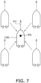
- the watercraft operating controller 30 keeps the watercraft 100 located in a setting position P0, while the bow of the watercraft 100 is kept oriented in a target direction H 1.
- the watercraft operating controller 30 determines, as the target direction H1, a direction in which the watercraft 100 is oriented in selecting the position keeping function with the input device 28.
- the watercraft operating controller 30 determines, as the setting position P0, a position in which the watercraft 100 is located in selecting the position keeping function with the input device 28.
- the watercraft operating controller 30 controls the thrust and the rudder angle of each marine propulsion device 1a, 1b such that the watercraft 100 is kept located in the setting position P0, while the bow thereof is kept oriented in the target direction H1.
- the control system 20 includes a data communication module (hereinafter referred to as "DCM") 33.
- the DCM 33 performs wireless communication with an external computer.
- the DCM 33 is capable of performing data transmission with the external computer through a mobile communication network 200.
- the mobile communication network 200 is, for instance, a network of a 3G, 4G, or 5G mobile communication system.
- the DCM 33 is communicable with a server 201.
- the DCM 33 is communicable with a user terminal 202.
- the user terminal 202 may be, for instance, a smartphone, a tablet, or a personal computer.
- the DCM 33 may be communicable with the user terminal 202 through the server 201.
- the watercraft operating controller 30 sends functional information, trouble information, and operational information to the server 201 through the DCM 33.
- the functional information which one of the automatic control functions is used and the position of the watercraft 100 located in a use of the used automatic control function are associated with each other.
- FIG. 8 is a schematic diagram showing a data structure of functional information 40. As shown in FIG. 8 , the functional information 40 contains identification data 41, time data 42, functional data 43, positional data 44, and weather data 45.
- the identification data 41 indicate an identifier of the watercraft 100.
- the identification data 41 may take the form of an identification number of the watercraft 100.
- the identification data 41 may indicate an identifier specifying the type of the watercraft 100.
- the time data 42 indicate a set of date and clock time when the automatic control function has been used.
- the functional data 43 indicate the automatic control function used in the watercraft 100.
- the positional data 44 indicate the position of the watercraft 100 when the automatic control function has been used.
- the positional data 44 contain, for instance, a set of latitude and longitude coordinates in the position of the watercraft 100.
- the weather data 45 indicate weather in the surroundings of the watercraft 100 when the automatic control function ha been used.
- the weather data 45 contains, for instance, a short-term atmospheric condition, an atmospheric pressure, a precipitation, a temperature, and a speed and a direction of wind.
- a short-term atmospheric condition is indicated by such expressions as sunny, cloudy, rainy, and foggy.
- the watercraft operating controller 30 in the use of the autopilot function, the watercraft operating controller 30 generates the functional information 40 by combining the following to each other: the identification data 41; the time data 42 indicating a set of date and clock time in a use of the autopilot function; the functional data 43 indicating the autopilot function; the positional data 44 indicating the position of the watercraft 100 in the use of the autopilot function; and the weather data 45 indicating weather in the use of the autopilot function.
- the watercraft operating controller 30 In the use of the position keeping function, the watercraft operating controller 30 generates the functional information 40 by combining the following to each other: the identification data 41; the time data 42 indicating a set of date and clock time in a use of the position keeping function; the functional data 43 indicating the position keeping function; the positional data 44 indicating the position of the watercraft 100 in the use of the position keeping function; and the weather data 45 indicating weather in the use of the position keeping function.
- the watercraft operating controller 30 sends the generated functional information 40 to the server 201 through the DCM 33.
- the watercraft operating controller 30 may accumulate and store a plurality of pieces of functional information 40 and may send the stored pieces of functional information 40 to the server 201 at predetermined intervals of time.
- the watercraft operating controller 30 may send the stored pieces of functional information 40 to the server 201 in response to a request from the server 201 or the user terminal 202.
- the watercraft operating controller 30 may send a piece of functional information 40 to the server 201 every time the piece of functional information 40 is generated.
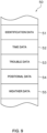
- FIG. 9 is a schematic diagram showing a data structure of trouble information 50.
- the trouble information 50 contains identification data 51, time data 52, trouble data 53, positional data 54, and weather data 55.
- the identification data 51 are similar to the identification data 41 contained in the functional information 40.
- the time data 52 indicate a set of date and clock time in an occurrence of a trouble.
- the trouble data 53 indicates the trouble occurred in each marine propulsion device 1a, 1b.
- the positional data 54 indicate the position of the watercraft 100 in the occurrence of the trouble.
- the weather data 55 indicate weather in the surroundings of the watercraft 100 in the occurrence of the trouble.
- the watercraft operating controller 30 in an occurrence of overheating of the drive source 2a, the watercraft operating controller 30 generates the trouble information 50 by combining the following to each other: the identification data 51; the time data 52 indicating a set of date and clock time in the occurrence of the overheating; the trouble data 53 indicating the overheating; the positional data 54 indicating the position of the watercraft 100 in the occurrence of the overheating; and the weather data 55 indicating weather in the occurrence of the overheating.
- the watercraft operating controller 30 In an occurrence of over-revolution of the drive source 2a, the watercraft operating controller 30 generates the trouble information 50 by combining the following to each other: the identification data 51; the time data 52 indicating a set of date and clock time in the occurrence of the over-revolution; the trouble data 53 indicating the over-revolution; the positional data 54 indicating the position of the watercraft 100 in the occurrence of the over-revolution; and the weather data 55 indicating weather in the occurrence of the over-revolution.
- the watercraft operating controller 30 sends the generated trouble information 50 to the server 201 through the DCM 33.
- the watercraft operating controller 30 may accumulate and store a plurality of pieces of trouble information 50 and may send the stored pieces of trouble information 50 to the server 201 at predetermined intervals of time.
- the watercraft operating controller 30 may send the stored pieces of trouble information 50 to the server 201 in response to a request from the server 201 or the user terminal 202.
- the watercraft operating controller 30 may send a piece of trouble information 50 to the server 201 every time the piece of trouble information 50 is generated.
- FIG. 10 is a schematic diagram showing a data structure of operational information 60.
- the operational information 60 contains identification data 61, time data 62, operational pattern data 63, positional data 64, and weather data 65.
- the identification data 61 are similar to the identification data 41 contained in the functional information 40.
- the time data 62 indicate a set of date and clock time in an operation performed by the user for each marine propulsion device 1a, 1b.
- the operational pattern data 63 indicate the operation performed by the user for each marine propulsion device 1a, 1b.
- the operation performed by the user for each marine propulsion device 1a, 1b indicates the content of the operation performed for the steering operating device 24, that of the operation performed for the throttle-shift operating device 25, that of the operation performed for the joystick 26, and combinations of the contents.
- the positional data 64 indicate the position of the watercraft 100 in the operation performed by the user for each marine propulsion device 1a, 1b.
- the weather data 65 indicate weather in the surroundings of the watercraft 100 in the operation performed by the user for each marine propulsion device 1a, 1b.
- the watercraft operating controller 30 in an operation performed by the user for the throttle-shift operating members 25a and 25b, the watercraft operating controller 30 generates the operational information 60 by combining the following to each other: the identification data 61; the time data 62 indicating a set of date and clock time in the operation performed for the throttle-shift operating members 25a and 25b; the operational pattern data 63 indicating the operation performed for the throttle-shift operating members 25a and 25b; the positional data 64 indicating the position of the watercraft 100 in the operation performed for the throttle-shift operating members 25a and 25b; and the weather data 65 indicating weather in the operation performed for the throttle-shift operating members 25a and 25b.
- the watercraft operating controller 30 In an operation performed by the user for the steering operating device 24, the watercraft operating controller 30 generates the operational information 60 by combining the following to each other: the identification data 61; the time data 62 indicating a set of date and clock time in the operation performed for the steering operating device 24; the operational pattern data 63 indicating the operation performed for the steering operating device 24; the positional data 64 indicating the position of the watercraft 100 in the operation performed for the steering operating device 24; and the weather data 65 indicating weather in the operation performed for the steering operating device 24.
- the watercraft operating controller 30 In an operation performed by the user for the joystick 26, the watercraft operating controller 30 generates the operational information 60 by combining the following to each other: the identification data 61; the time data 62 indicating a set of date and clock time in the operation performed for the joystick 26; the operational pattern data 63 indicating the operation performed for the joystick 26; the positional data 64 indicating the position of the watercraft 100 in the operation performed for the joystick 26; and the weather data 65 indicating weather in the operation performed for the joystick 26.
- the watercraft operating controller 30 sends the generated operational information 60 to the server 201 through the DCM 33.
- the watercraft operating controller 30 may accumulate and store a plurality of pieces of operational information 60 and may send the stored pieces of operational information 60 to the server 201 at predetermined intervals of time.
- the watercraft operating controller 30 may send the stored pieces of operational information 60 to the server 201 in response to a request from the server 201 or the user terminal 202.
- the watercraft operating controller 30 may send a piece of operational information 60 to the server 201 every time the piece of operational information 60 is generated.
- the server 201 receives the functional information 40 from the watercraft operating controller 30.
- the server 201 records the received functional information 40 in a database for the functional information 40 and accumulates and stores therein the recorded functional information 40.
- the server 201 receives the trouble information 50 from the watercraft operating controller 30.
- the server 201 records the received trouble information 50 in a database for the trouble information 50 and accumulates and stores therein the recorded trouble information 50.
- the server 201 receives the operational information 60 from the watercraft operating controller 30.
- the server 201 records the received operational information 60 in a database for the operational information 60 and accumulates and stores therein the recorded operational information 60.
- the functional information 40, the trouble information 50, and the operational information 60 are sent to the server 201.
- the functional information 40 the one used in the automatic control functions and the position of the watercraft 100 in the use of the automatic control function are associated with each other.
- the trouble information 50 the occurred trouble and the position of the watercraft 100 in the occurrence of the occurred trouble are associated with each other.
- the operational information 60 the performed operational pattern and the position of the watercraft 100 in performing the performed operational pattern are associated with each other. Therefore, the functional information 40, the trouble information 50, and the operational information 60 are collected by the server 201, whereby user convenience can be enhanced.
- the server 201 may specify a region in which a specific trouble occurs frequently by analyzing pieces of trouble information 50 transmitted thereto from a variety of watercraft 100.
- the server 201 may display a map indicating the specified region on a website on the Internet, an application installed in the user terminal 202, or the display 27.
- the server 201 may send an alert to the watercraft 100 that passes through the specified region.
- the server 201 may suggest a specific watercraft 100 a method of appropriately operating the specific watercraft 100 by analyzing the operational information 60 of the specific watercraft 100. For example, when the user manually operates the watercraft 100 such that the watercraft 100 is kept in a fixed spot, the server 201 may suggest the user to use the position keeping function. The server 201 may suggest an appropriate method of operating the watercraft 100 in the form of display on the display 27 or the application installed in the user terminal 202 or in the form of sending an e-mail.
- Each marine propulsion device 1a, 1b is not limited to the outboard motor, and alternatively, may be another type of propulsion device such as an inboard engine outboard drive or a jet propulsion device.
- the structure of each marine propulsion device 1a, 1b is not limited to that in the embodiment described above and may be changed.
- each drive source 2a, 2b may be an electric motor.
- the number of marine propulsion devices is not limited to two. The number of marine propulsion devices may be one or may be more than two.
- the watercraft operating controller 30 may generate part of the functional information 40, the trouble information 50, and the operational information 60 and may send the generated information to the server 201.
- the functional information 40, the trouble information 50, and the operational information 60 are not limited to those in the embodiment described above and may be changed.
- the identification data, the time data, or the weather data may be omitted.
- the automatic control functions are not limited to that in the embodiment described above and may be changed.
- the automatic control functions may include a pattern control function for moving the watercraft 100 along a specific trajectory having a zigzag shape, a spiral shape, or so forth.
- the trouble information 50 is not limited to that in the embodiment described above and may be changed.
- the trouble information 50 may include another trouble such as an occurrence of engine stall or a jump of the watercraft 100.
- the operational information 60 is not limited to that in the embodiment described above and may be changed.
- the operation of the steering operating device 24 may be omitted.
- the operation of the throttle-shift operating device 25 may be omitted.
- the operation of the joystick 26 may be omitted.
Landscapes
- Engineering & Computer Science (AREA)
- Chemical & Material Sciences (AREA)
- Combustion & Propulsion (AREA)
- Mechanical Engineering (AREA)
- Ocean & Marine Engineering (AREA)
- Life Sciences & Earth Sciences (AREA)
- Atmospheric Sciences (AREA)
- Environmental & Geological Engineering (AREA)
- Control Of Vehicle Engines Or Engines For Specific Uses (AREA)
- Control Of Position, Course, Altitude, Or Attitude Of Moving Bodies (AREA)
Abstract
Description
- The present invention relates to a system for and a method of controlling a watercraft.
- A type of system for controlling a watercraft has an automatic control function. In the automatic control function, the system automatically controls a marine propulsion device attached to the watercraft. For example, a system for controlling a watercraft described in
JP 2020-168921 A - Besides, the aforementioned system for controlling a watercraft includes an operating member to be operated by a user. The operating member includes a shift lever, a steering wheel, and/or a joystick. The user operates the shift lever to perform switching between a forward moving action and a rearward moving action by the marine propulsion device. The user operates the steering wheel to turn the watercraft. The user operates the joystick to move the watercraft forward, rearward, rightward, and leftward.
- The maritime environment is greater in diversity than the onshore environment. Because of this, it is not easy to grasp the following information at the sea: in what kind of environment the automatic control function is used by the user; what kind of automatic control function is used by the user; and in what kind of operational pattern the operating member is operated by the user. The information described herein makes it possible to grasp how the marine propulsion device is used by the user; hence, the information can be useful for enhancement in user convenience.
- Besides, when a trouble occurs in the watercraft at the sea, it is not easy to solve the trouble. If it is possible to grasp what kind of environment the trouble occurs in and what kind of trouble occurs by collecting information, such information collection can be helpful to tackle a recurrence of the trouble; consequently, user convenience can be enhanced.
- It is an object of the present invention to enhance user convenience by collecting information indicating what kind of environment a marine propulsion device is used in, how the marine propulsion device is used, or what kind of trouble occurs.
- A system according to an aspect of the present invention relates to a system for controlling a watercraft including a marine propulsion device. The system according to the present aspect includes a data communication module, a position sensor, and a controller. The data communication module performs wireless communication with an external computer. The position sensor detects a position of the watercraft. The controller obtains the position of the watercraft. The controller sends at least one of functional information, trouble information, and operational information to the external computer through the data communication module. In the functional information, an automatic control function used for the marine propulsion device and the position of the watercraft when the automatic control function is used are associated with each other. In the trouble information, a trouble occurred in the marine propulsion device and the position of the watercraft when the trouble is occurred are associated with each other. In the operational information, an operational pattern performed by a user for the marine propulsion device and the position of the watercraft when the operational pattern is performed are associated with each other.
- A method according to another aspect of the present invention relates to a method of controlling a watercraft including a marine propulsion device. The method according to the present aspect includes the following: obtaining a position of the watercraft; and sending at least one of functional information, trouble information, and operational information to an external computer. In the functional information, an automatic control function used for the marine propulsion device and the position of the watercraft when the automatic control function is used are associated with each other. In the trouble information, a trouble occurred in the marine propulsion device and the position of the watercraft when the trouble is occurred are associated with each other. In the operational information, an operational pattern performed by a user for the marine propulsion device and the position of the watercraft when the operational pattern is performed are associated with each other.
- Overall, according to the present invention, at least one of the functional information, the trouble information, and the operational information is sent to the external computer. In the functional information, the used automatic control function and the position of the watercraft obtained in the use of the automatic control function are associated with each other. In the trouble information, the occurred trouble and the position of the watercraft obtained in the occurrence of the trouble are associated with each other. In the operational information, the operational pattern and the position of the watercraft obtained in the performance of the operational pattern are associated with each other. Therefore, at least one of the functional information, the trouble information, and the operational information is collected by the external computer, whereby user convenience can be enhanced.
-
-
FIG. 1 is a perspective view of a watercraft according to an embodiment. -
FIG. 2 is a side view of a marine propulsion device. -
FIG. 3 is a schematic diagram showing a configuration of a system for controlling the watercraft. -
FIG. 4 is a schematic diagram showing a control executed for the marine propulsion device by a joystick. -
FIG. 5 is a schematic diagram showing another control executed for the marine propulsion device by the joystick. -
FIG. 6 is a diagram showing motions of the watercraft in an autopilot function. -
FIG. 7 is a diagram showing motions of the watercraft in a position keeping function. -
FIG. 8 is a schematic diagram showing a data structure of functional information. -
FIG. 9 is a schematic diagram showing a data structure of trouble data. -
FIG. 10 is a schematic diagram showing a data structure of operational information. - A preferred embodiment will be hereinafter explained with reference to drawings.
FIG. 1 is a perspective view of awatercraft 100 to whichmarine propulsion devices marine propulsion devices watercraft 100 as a plurality of marine propulsion devices. In the present embodiment, themarine propulsion devices marine propulsion devices watercraft 100. Themarine propulsion devices watercraft 100. Specifically, themarine propulsion device 1a is disposed on the port side of thewatercraft 100. Themarine propulsion device 1b is disposed on the starboard side of thewatercraft 100. Eachmarine propulsion device watercraft 100. -
FIG. 2 is a side view of themarine propulsion device 1a. The structure of themarine propulsion device 1a will be hereinafter explained; however, the structure of themarine propulsion device 1a is also true of themarine propulsion device 1b. Themarine propulsion device 1a is attached to thewatercraft 100 through abracket 11a. Thebracket 11a supports themarine propulsion device 1a such that themarine propulsion device 1a is rotatable about asteering shaft 12a. Thesteering shaft 12a extends in the up-and-down direction of themarine propulsion device 1a. - The
marine propulsion device 1a includes adrive source 2a, adrive shaft 3a, apropeller shaft 4a, ashift mechanism 5a, and ahousing 10a. Thedrive source 2a generates the thrust for propelling thewatercraft 100. Thedrive source 2a is an internal combustion engine. Thedrive source 2a includes acrankshaft 13a. Thecrankshaft 13a extends in the up-and-down direction of themarine propulsion device 1a. - The
drive shaft 3a is connected to thecrankshaft 13a. Thedrive shaft 3a extends in the up-and-down direction of themarine propulsion device 1a. Thepropeller shaft 4a extends in the back-and-forth direction of themarine propulsion device 1a. Thepropeller shaft 4a is connected to thedrive shaft 3a through theshift mechanism 5a. A propeller 6a is attached to thepropeller shaft 4a. - The
shift mechanism 5a includes a forward movinggear 14a, a rearward movinggear 15a, and a dog clutch 16a. When gear engagement of eachgear dog clutch 16a, theshift mechanism 5a is switched among a forward moving state, a rearward moving state, and a neutral state. When set in the forward moving state, theshift mechanism 5a transmits rotation, directed to move thewatercraft 100 forward, from thedrive shaft 3a to thepropeller shaft 4a. When set in the rearward moving state, theshift mechanism 5a transmits rotation, directed to move thewatercraft 100 rearward, from thedrive shaft 3a to thepropeller shaft 4a. When set in the neutral state, theshift mechanism 5a does not transmit rotation from thedrive shaft 3a to thepropeller shaft 4a. Thehousing 10a accommodates thedrive source 2a, thedrive shaft 3a, thepropeller shaft 4a, and theshift mechanism 5a. -
FIG. 3 is a schematic diagram for showing a configuration of acontrol system 20 for thewatercraft 100. As shown inFIG. 3 , themarine propulsion device 1a includes ashift actuator 7a and asteering actuator 8a. - The
shift actuator 7a is connected to the dog clutch 16a of theshift mechanism 5a. Theshift actuator 7a actuates the dog clutch 16a to switch gear engagement of eachgear shift mechanism 5a is switched among the forward moving state, the rearward moving state, and the neutral state. Theshift actuator 7a is, for instance, an electric motor. However, theshift actuator 7a may be another type of actuator such as an electric cylinder, a hydraulic motor, or a hydraulic cylinder. - The
steering actuator 8a is connected to themarine propulsion device 1a. Thesteering actuator 8a rotates themarine propulsion device 1a about thesteering shaft 12a. Accordingly, themarine propulsion device 1a is changed in rudder angle. Thesteering actuator 8a is, for instance, an electric motor. However, thesteering actuator 8a may be another type of actuator such as an electric cylinder, a hydraulic motor, or a hydraulic cylinder. - The
marine propulsion device 1a includes afirst ECU 9a. Thefirst ECU 9a includes a processor such as a CPU (Central Processing Unit) and memories such as a RAM (Random Access Memory) and a ROM (Read Only Memory). Thefirst ECU 9a stores programs and data for controlling themarine propulsion device 1a. Thefirst ECU 9a controls thedrive source 2a. - The
marine propulsion device 1b includes adrive source 2b, ashift actuator 7b, asteering actuator 8b, and asecond ECU 9b. Thedrive source 2b, theshift actuator 7b, thesteering actuator 8b, and thesecond ECU 9b in themarine propulsion device 1b are configured in similar manner to thedrive source 2a, theshift actuator 7a, thesteering actuator 8a, and thefirst ECU 9a in themarine propulsion device 1a, respectively. - The
control system 20 includes asteering operating device 24, a throttle-shift operating device 25, and ajoystick 26. Thesteering operating device 24, the throttle-shift operating device 25, and thejoystick 26 are disposed in a cockpit of thewatercraft 100. - The
steering operating device 24 is operable by a user to adjust the rudder angle of eachmarine propulsion device steering operating device 24 includes, for instance, a steering wheel. Thesteering operating device 24 outputs a steering signal indicating the operating position thereof. - The throttle-
shift operating device 25 includes a first throttle-shift operating member 25a and a second throttle-shift operating member 25b. Each of the first and second throttle-shift operating members shift operating members - The first throttle-
shift operating member 25a is operable by the user to regulate the output rotational speed of themarine propulsion device 1a. Besides, the first throttle-shift operating member 25a is operable by the user to perform switching between a forward moving action and a rearward moving action by themarine propulsion device 1a. The first throttle-shift operating member 25a is operable from a neutral position to a forward moving position and a rearward moving position. The throttle-shift operating device 25 outputs a throttle signal indicating the operating position of the first throttle-shift operating member 25a. - The second throttle-
shift operating member 25b is operable by the user to regulate the output rotational speed of themarine propulsion device 1b. Besides, the second throttle-shift operating member 25b is operable by the user to perform switching between a forward moving action and a rearward moving action by themarine propulsion device 1b. The second throttle-shift operating member 25b is configured in similar manner to the first throttle-shift operating member 25a. The throttle-shift operating device 25 outputs a throttle signal indicating the operating position of the second throttle-shift operating member 25b. - The
joystick 26 is operable by the user to move thewatercraft 100 forward, rearward, rightward, and leftward. Thejoystick 26 is operable from a neutral position in front, rear, right, and left directions. Thejoystick 26 may be operable from the neutral position in all directions. Thejoystick 26 is operable by the user to cause thewatercraft 100 to perform a bow turning motion. Thejoystick 26 is operable about a center axis Ax1 thereof by a twist operation. Thejoystick 26 outputs a joystick signal indicating the operating position thereof. - The
control system 20 includes awatercraft operating controller 30. Thewatercraft operating controller 30 includes a processor such as a CPU, memories such as a RAM and a ROM, and a storage such as an HDD (Hard Disk Drive) or an SSD (Solid State Drive). Thewatercraft operating controller 30 stores programs and data for controlling themarine propulsion devices watercraft operating controller 30 is connected to the first andsecond ECUs watercraft operating controller 30 is connected to thesteering operating device 24, the throttle-shift operating device 25, and thejoystick 26 through wired or wireless communication. - The
watercraft operating controller 30 receives the steering signal from thesteering operating device 24. Thewatercraft operating controller 30 receives the throttle signals from the throttle-shift operating device 25. Thewatercraft operating controller 30 outputs command signals to the first andsecond ECUs shift actuator 7a and thesteering actuator 8a through thefirst ECU 9a. The command signals are sent to theshift actuator 7b and thesteering actuator 8b through thesecond ECU 9b. - For example, the
watercraft operating controller 30 outputs the command signal to theshift actuator 7a in accordance with the operating position of the first throttle-shift operating member 25a. In response, switching between the forward moving action and the rearward moving action by themarine propulsion device 1a is made. Besides, thewatercraft operating controller 30 outputs a throttle command for thedrive source 2a in accordance with the operating position of the first throttle-shift operating member 25a. Thefirst ECU 9a controls the output rotational speed of themarine propulsion device 1a in accordance with the throttle command. - The
watercraft operating controller 30 outputs a command signal for theshift actuator 7b in accordance with the operating position of the second throttle-shift operating member 25b. In response, switching between the forward moving action and the rearward moving action by themarine propulsion device 1b is made. Besides, thewatercraft operating controller 30 outputs a throttle command for thedrive source 2b in accordance with the operating position of the second throttle-shift operating member 25b. Thesecond ECU 9b controls the output rotational speed of themarine propulsion device 1b in accordance with the throttle command. - The
watercraft operating controller 30 outputs command signals for thesteering actuators steering operating device 24. Thewatercraft operating controller 30 controls the rudder angles of themarine propulsion devices steering operating device 24. - When the
steering operating device 24 is operated leftward from a neutral position, thewatercraft operating controller 30 controls thesteering actuators marine propulsion devices watercraft 100 thereby turns leftward. When thesteering operating device 24 is operated rightward from the neutral position, thewatercraft operating controller 30 controls thesteering actuators marine propulsion devices watercraft 100 thereby turns rightward. - The
watercraft operating controller 30 outputs the command signals to each drivesource shift actuator steering actuator joystick 26. When thejoystick 26 is operated in any of front, rear, right, and left directions, thewatercraft operating controller 30 controls themarine propulsion devices watercraft 100 moves in a direction corresponding to the operating direction of thejoystick 26. - For example, when thejoystick26 is operated rightward, as shown in
FIG. 4 , thewatercraft operating controller 30 controls the thrust and the rudder angle of eachmarine propulsion device marine propulsion device 1a and the thrust (F2) of themarine propulsion device 1b is oriented rightward, while extending from the center of gravity (G1) of thewatercraft 100. Accordingly, thewatercraft 100 performs a rightward translational motion. Likewise, when thejoystick 26 is operated leftward, thewatercraft operating controller 30 controls the thrust F1, F2 and the rudder angle of eachmarine propulsion device marine propulsion device 1a and the thrust F2 of themarine propulsion device 1b is oriented leftward, while extending from the center of gravity G1 of thewatercraft 100. - When the
joystick 26 is twisted, thewatercraft operating controller 30 controls eachmarine propulsion device watercraft 100 performs a bow turning motion in a direction corresponding to the twist direction of thejoystick 26. For example, when thejoystick 26 is twisted clockwise, as shown inFIG. 5 , thewatercraft operating controller 30 causes themarine propulsion device 1a to generate a thrust oriented in the forward moving direction, and simultaneously, causes themarine propulsion device 1b to generate a thrust oriented in the rearward moving direction. Accordingly, thewatercraft 100 performs a clockwise bow turning motion. Likewise, when thejoystick 26 is twisted counterclockwise, thewatercraft operating controller 30 causes themarine propulsion device 1b to generate a thrust oriented in the forward moving direction, and simultaneously, causes themarine propulsion device 1a to generate a thrust oriented in the rearward moving direction. Accordingly, thewatercraft 100 performs a counterclockwise bow turning motion. - As shown in
FIG. 3 , thecontrol system 20 includes adisplay 27 and aninput device 28. Thedisplay 27 displays information regarding eachmarine propulsion device display 27 displays an image in response to an image signal inputted thereto. - The
input device 28 receives an operational input by the user. Theinput device 28 outputs an input signal indicating the operational input by the user. Theinput device 28 may be disposed in thejoystick 26. Alternatively, theinput device 28 may be disposed in a position separated from thejoystick 26. Theinput device 28 includes at least one switch. Theinput device 28 may not necessarily include the at least one switch, and alternatively, may include another type of device such as a touchscreen. - The
marine propulsion device 1a includes arotational speed sensor 17a and atemperature sensor 18a. Therotational speed sensor 17a outputs a rotational speed signal indicating the output rotational speed of thedrive source 2a. Thetemperature sensor 18a outputs a temperature signal indicating the temperature of thedrive source 2a. Thewatercraft operating controller 30 receives the rotational speed signal from therotational speed sensor 17a. Thewatercraft operating controller 30 receives the temperature signal from thetemperature sensor 18a. - The
marine propulsion device 1b includes arotational speed sensor 17b and atemperature sensor 18b. Therotational speed sensor 17b outputs a rotational speed signal indicating the output rotational speed of thedrive source 2b. Thetemperature sensor 18b outputs a temperature signal indicating the temperature of thedrive source 2b. Thewatercraft operating controller 30 receives the rotational speed signal from therotational speed sensor 17b. Thewatercraft operating controller 30 receives the temperature signal from thetemperature sensor 18b. - The
watercraft operating controller 30 determines whether or not over-revolution of thedrive source 2a is occurring based on the output rotational speed of thedrive source 2a. For example, when the output rotational speed of thedrive source 2a is greater than or equal to a predetermined threshold of rotational speed, thewatercraft operating controller 30 determines that over-revolution of thedrive source 2a is occurring. When determining that over-revolution of thedrive source 2a is occurring, thewatercraft operating controller 30 causes thedisplay 27 to display an alert. Alternatively, when determining that over-revolution of thedrive source 2a is occurring, thewatercraft operating controller 30 may turn on a warning lamp. Likewise, thewatercraft operating controller 30 determines whether or not over-revolution of thedrive source 2b is occurring based on the output rotational speed of thedrive source 2b. - The
watercraft operating controller 30 determines whether or not overheating of thedrive source 2a is occurring based on the temperature of thedrive source 2a. For example, when the temperature of thedrive source 2a is greater than or equal to a predetermined threshold of temperature, thewatercraft operating controller 30 determines that overheating of thedrive source 2a is occurring. When determining that overheating of thedrive source 2a is occurring, thewatercraft operating controller 30 causes thedisplay 27 to display an alert. Alternatively, when determining that overheating of thedrive source 2a is occurring, thewatercraft operating controller 30 may turn on a warning lamp. Likewise, thewatercraft operating controller 30 determines whether or not overheating of thedrive source 2b is occurring based on the temperature of thedrive source 2b. - The
control system 20 includes aposition sensor 31. Theposition sensor 31 detects the position of thewatercraft 100. Theposition sensor 31 is a GNSS (Global Navigation Satellite System) receiver such as a GPS (Global Positioning System) receiver. However, theposition sensor 31 may be a type of sensor other than the GNSS receiver. Theposition sensor 31 outputs a position signal indicating the position of thewatercraft 100. Thewatercraft operating controller 30 is connected to theposition sensor 31 in communicable manner. Thewatercraft operating controller 30 obtains the position of thewatercraft 100 based on the position signal transmitted thereto from theposition sensor 31. Besides, thewatercraft operating controller 30 obtains the velocity of thewatercraft 100 based on the position signal transmitted thereto from theposition sensor 31. Thecontrol system 20 may include another type of sensor for detecting the velocity of thewatercraft 100. - The system includes a
compass direction sensor 32. Thecompass direction sensor 32 detects a compass direction of the bow of thewatercraft 100. Thecompass direction sensor 32 is, for instance, an IMU (Inertial Measurement Unit). However, thecompass direction sensor 32 may be a type of sensor other than the IMU. Thecompass direction sensor 32 outputs a compass direction signal indicating the compass direction of the bow of thewatercraft 100. Thewatercraft operating controller 30 is connected to thecompass direction sensor 32 in communicable manner. Thewatercraft operating controller 30 obtains the compass direction of thewatercraft 100 based on the compass direction signal transmitted thereto from thecompass direction sensor 32. - The
watercraft operating controller 30 has automatic control functions of thewatercraft 100. Thewatercraft operating controller 30 automatically controls thewatercraft 100 under the automatic control functions based on the position and the compass direction of thewatercraft 100. Theinput device 28 is operable by the user to select one of the automatic control functions. Theinput device 28 outputs an input signal indicating which one of the automatic control functions has been selected by the user. Thewatercraft operating controller 30 receives the input signal from theinput device 28. Thewatercraft operating controller 30 automatically controls thewatercraft 100 in accordance with the selected one of the automatic control functions. - The automatic control functions include an autopilot function and a position keeping function. Under the autopilot function, the
watercraft operating controller 30 controls eachmarine propulsion device watercraft 100 moves in a predetermined trajectory. Under the position keeping function, thewatercraft operating controller 30 controls eachmarine propulsion device watercraft 100 is kept located in a predetermined position. - As shown in
Fig. 6 , under the autopilot function, thewatercraft operating controller 30 controls eachmarine propulsion device watercraft 100 moves along a route R1 to be set. The user sets the route R1 with theinput device 28. When described in detail, the user specifies a plurality of target spots P1 to P4, including the target spot P4 as a destination, with theinput device 28. For example, the user arbitrarily selects the target spots P1 to P4 on a map displayed on thedisplay 27. Theinput device 28 outputs an operating signal indicating the plural target spots P1 to P4 selected by the user. The number of target spots may be one. Thewatercraft operating controller 30 computes the route R1 on which the target spots P1 to P4 are located. Thewatercraft operating controller 30 controls the thrust and the rudder angle of eachmarine propulsion device watercraft 100 moves along the route R1. - As shown in
FIG. 7 , under the position keeping function, thewatercraft operating controller 30 keeps thewatercraft 100 located in a setting position P0, while the bow of thewatercraft 100 is kept oriented in atarget direction H 1. For example, thewatercraft operating controller 30 determines, as the target direction H1, a direction in which thewatercraft 100 is oriented in selecting the position keeping function with theinput device 28. Thewatercraft operating controller 30 determines, as the setting position P0, a position in which thewatercraft 100 is located in selecting the position keeping function with theinput device 28. Thewatercraft operating controller 30 controls the thrust and the rudder angle of eachmarine propulsion device watercraft 100 is kept located in the setting position P0, while the bow thereof is kept oriented in the target direction H1. - The
control system 20 includes a data communication module (hereinafter referred to as "DCM") 33. TheDCM 33 performs wireless communication with an external computer. For example, theDCM 33 is capable of performing data transmission with the external computer through amobile communication network 200. Themobile communication network 200 is, for instance, a network of a 3G, 4G, or 5G mobile communication system. TheDCM 33 is communicable with aserver 201. TheDCM 33 is communicable with auser terminal 202. Theuser terminal 202 may be, for instance, a smartphone, a tablet, or a personal computer. TheDCM 33 may be communicable with theuser terminal 202 through theserver 201. - The
watercraft operating controller 30 sends functional information, trouble information, and operational information to theserver 201 through theDCM 33. In the functional information, which one of the automatic control functions is used and the position of thewatercraft 100 located in a use of the used automatic control function are associated with each other.FIG. 8 is a schematic diagram showing a data structure offunctional information 40. As shown inFIG. 8 , thefunctional information 40 containsidentification data 41,time data 42,functional data 43,positional data 44, andweather data 45. - The
identification data 41 indicate an identifier of thewatercraft 100. For example, theidentification data 41 may take the form of an identification number of thewatercraft 100. Alternatively, theidentification data 41 may indicate an identifier specifying the type of thewatercraft 100. Thetime data 42 indicate a set of date and clock time when the automatic control function has been used. Thefunctional data 43 indicate the automatic control function used in thewatercraft 100. Thepositional data 44 indicate the position of thewatercraft 100 when the automatic control function has been used. Thepositional data 44 contain, for instance, a set of latitude and longitude coordinates in the position of thewatercraft 100. Theweather data 45 indicate weather in the surroundings of thewatercraft 100 when the automatic control function ha been used. Theweather data 45 contains, for instance, a short-term atmospheric condition, an atmospheric pressure, a precipitation, a temperature, and a speed and a direction of wind. For example, the short-term atmospheric condition is indicated by such expressions as sunny, cloudy, rainy, and foggy. - For example, in the use of the autopilot function, the
watercraft operating controller 30 generates thefunctional information 40 by combining the following to each other: theidentification data 41; thetime data 42 indicating a set of date and clock time in a use of the autopilot function; thefunctional data 43 indicating the autopilot function; thepositional data 44 indicating the position of thewatercraft 100 in the use of the autopilot function; and theweather data 45 indicating weather in the use of the autopilot function. - In the use of the position keeping function, the
watercraft operating controller 30 generates thefunctional information 40 by combining the following to each other: theidentification data 41; thetime data 42 indicating a set of date and clock time in a use of the position keeping function; thefunctional data 43 indicating the position keeping function; thepositional data 44 indicating the position of thewatercraft 100 in the use of the position keeping function; and theweather data 45 indicating weather in the use of the position keeping function. - Then, the
watercraft operating controller 30 sends the generatedfunctional information 40 to theserver 201 through theDCM 33. Thewatercraft operating controller 30 may accumulate and store a plurality of pieces offunctional information 40 and may send the stored pieces offunctional information 40 to theserver 201 at predetermined intervals of time. Thewatercraft operating controller 30 may send the stored pieces offunctional information 40 to theserver 201 in response to a request from theserver 201 or theuser terminal 202. Thewatercraft operating controller 30 may send a piece offunctional information 40 to theserver 201 every time the piece offunctional information 40 is generated. - In the trouble information, a trouble occurred in each
marine propulsion device watercraft 100 in an occurrence of the trouble are associated with each other.FIG. 9 is a schematic diagram showing a data structure oftrouble information 50. As shown inFIG. 9 , thetrouble information 50 containsidentification data 51,time data 52,trouble data 53,positional data 54, andweather data 55. - The
identification data 51 are similar to theidentification data 41 contained in thefunctional information 40. Thetime data 52 indicate a set of date and clock time in an occurrence of a trouble. Thetrouble data 53 indicates the trouble occurred in eachmarine propulsion device positional data 54 indicate the position of thewatercraft 100 in the occurrence of the trouble. Theweather data 55 indicate weather in the surroundings of thewatercraft 100 in the occurrence of the trouble. - For example, in an occurrence of overheating of the
drive source 2a, thewatercraft operating controller 30 generates thetrouble information 50 by combining the following to each other: theidentification data 51; thetime data 52 indicating a set of date and clock time in the occurrence of the overheating; thetrouble data 53 indicating the overheating; thepositional data 54 indicating the position of thewatercraft 100 in the occurrence of the overheating; and theweather data 55 indicating weather in the occurrence of the overheating. - In an occurrence of over-revolution of the
drive source 2a, thewatercraft operating controller 30 generates thetrouble information 50 by combining the following to each other: theidentification data 51; thetime data 52 indicating a set of date and clock time in the occurrence of the over-revolution; thetrouble data 53 indicating the over-revolution; thepositional data 54 indicating the position of thewatercraft 100 in the occurrence of the over-revolution; and theweather data 55 indicating weather in the occurrence of the over-revolution. - Then, the
watercraft operating controller 30 sends the generatedtrouble information 50 to theserver 201 through theDCM 33. Thewatercraft operating controller 30 may accumulate and store a plurality of pieces oftrouble information 50 and may send the stored pieces oftrouble information 50 to theserver 201 at predetermined intervals of time. Thewatercraft operating controller 30 may send the stored pieces oftrouble information 50 to theserver 201 in response to a request from theserver 201 or theuser terminal 202. Thewatercraft operating controller 30 may send a piece oftrouble information 50 to theserver 201 every time the piece oftrouble information 50 is generated. - In the operational information, an operational pattern performed by the user for each
marine propulsion device watercraft 100 in performing the operational pattern are associated with each other.FIG. 10 is a schematic diagram showing a data structure ofoperational information 60. As shown inFIG. 9 , theoperational information 60 containsidentification data 61,time data 62,operational pattern data 63,positional data 64, andweather data 65. - The
identification data 61 are similar to theidentification data 41 contained in thefunctional information 40. Thetime data 62 indicate a set of date and clock time in an operation performed by the user for eachmarine propulsion device operational pattern data 63 indicate the operation performed by the user for eachmarine propulsion device marine propulsion device steering operating device 24, that of the operation performed for the throttle-shift operating device 25, that of the operation performed for thejoystick 26, and combinations of the contents. Thepositional data 64 indicate the position of thewatercraft 100 in the operation performed by the user for eachmarine propulsion device weather data 65 indicate weather in the surroundings of thewatercraft 100 in the operation performed by the user for eachmarine propulsion device - For example, in an operation performed by the user for the throttle-
shift operating members watercraft operating controller 30 generates theoperational information 60 by combining the following to each other: theidentification data 61; thetime data 62 indicating a set of date and clock time in the operation performed for the throttle-shift operating members operational pattern data 63 indicating the operation performed for the throttle-shift operating members positional data 64 indicating the position of thewatercraft 100 in the operation performed for the throttle-shift operating members weather data 65 indicating weather in the operation performed for the throttle-shift operating members - In an operation performed by the user for the
steering operating device 24, thewatercraft operating controller 30 generates theoperational information 60 by combining the following to each other: theidentification data 61; thetime data 62 indicating a set of date and clock time in the operation performed for thesteering operating device 24; theoperational pattern data 63 indicating the operation performed for thesteering operating device 24; thepositional data 64 indicating the position of thewatercraft 100 in the operation performed for thesteering operating device 24; and theweather data 65 indicating weather in the operation performed for thesteering operating device 24. - In an operation performed by the user for the
joystick 26, thewatercraft operating controller 30 generates theoperational information 60 by combining the following to each other: theidentification data 61; thetime data 62 indicating a set of date and clock time in the operation performed for thejoystick 26; theoperational pattern data 63 indicating the operation performed for thejoystick 26; thepositional data 64 indicating the position of thewatercraft 100 in the operation performed for thejoystick 26; and theweather data 65 indicating weather in the operation performed for thejoystick 26. - Then, the
watercraft operating controller 30 sends the generatedoperational information 60 to theserver 201 through theDCM 33. Thewatercraft operating controller 30 may accumulate and store a plurality of pieces ofoperational information 60 and may send the stored pieces ofoperational information 60 to theserver 201 at predetermined intervals of time. Thewatercraft operating controller 30 may send the stored pieces ofoperational information 60 to theserver 201 in response to a request from theserver 201 or theuser terminal 202. Thewatercraft operating controller 30 may send a piece ofoperational information 60 to theserver 201 every time the piece ofoperational information 60 is generated. - The
server 201 receives thefunctional information 40 from thewatercraft operating controller 30. Theserver 201 records the receivedfunctional information 40 in a database for thefunctional information 40 and accumulates and stores therein the recordedfunctional information 40. Theserver 201 receives thetrouble information 50 from thewatercraft operating controller 30. Theserver 201 records the receivedtrouble information 50 in a database for thetrouble information 50 and accumulates and stores therein the recordedtrouble information 50. Theserver 201 receives theoperational information 60 from thewatercraft operating controller 30. Theserver 201 records the receivedoperational information 60 in a database for theoperational information 60 and accumulates and stores therein the recordedoperational information 60. - In the
control system 20 according to the present embodiment, thefunctional information 40, thetrouble information 50, and theoperational information 60 are sent to theserver 201. In thefunctional information 40, the one used in the automatic control functions and the position of thewatercraft 100 in the use of the automatic control function are associated with each other. In thetrouble information 50, the occurred trouble and the position of thewatercraft 100 in the occurrence of the occurred trouble are associated with each other. In theoperational information 60, the performed operational pattern and the position of thewatercraft 100 in performing the performed operational pattern are associated with each other. Therefore, thefunctional information 40, thetrouble information 50, and theoperational information 60 are collected by theserver 201, whereby user convenience can be enhanced. - For example, the
server 201 may specify a region in which a specific trouble occurs frequently by analyzing pieces oftrouble information 50 transmitted thereto from a variety ofwatercraft 100. Theserver 201 may display a map indicating the specified region on a website on the Internet, an application installed in theuser terminal 202, or thedisplay 27. Alternatively, theserver 201 may send an alert to thewatercraft 100 that passes through the specified region. - The
server 201 may suggest a specific watercraft 100 a method of appropriately operating thespecific watercraft 100 by analyzing theoperational information 60 of thespecific watercraft 100. For example, when the user manually operates thewatercraft 100 such that thewatercraft 100 is kept in a fixed spot, theserver 201 may suggest the user to use the position keeping function. Theserver 201 may suggest an appropriate method of operating thewatercraft 100 in the form of display on thedisplay 27 or the application installed in theuser terminal 202 or in the form of sending an e-mail. - One embodiment of the present invention has been explained above. However, the present invention is not limited to the embodiment described above, and a variety of changes can be made without departing from the gist of the present invention.
- Each
marine propulsion device marine propulsion device drive source - The
watercraft operating controller 30 may generate part of thefunctional information 40, thetrouble information 50, and theoperational information 60 and may send the generated information to theserver 201. Thefunctional information 40, thetrouble information 50, and theoperational information 60 are not limited to those in the embodiment described above and may be changed. For example, the identification data, the time data, or the weather data may be omitted. The automatic control functions are not limited to that in the embodiment described above and may be changed. For example, the automatic control functions may include a pattern control function for moving thewatercraft 100 along a specific trajectory having a zigzag shape, a spiral shape, or so forth. - The
trouble information 50 is not limited to that in the embodiment described above and may be changed. For example, thetrouble information 50 may include another trouble such as an occurrence of engine stall or a jump of thewatercraft 100. Theoperational information 60 is not limited to that in the embodiment described above and may be changed. For example, the operation of thesteering operating device 24 may be omitted. The operation of the throttle-shift operating device 25 may be omitted. The operation of thejoystick 26 may be omitted. -
- 1a: Marine propulsion device
- 2a: Drive source
- 25a: First throttle-shift operating member
- 26: Joystick
- 30: Watercraft operating controller
- 31: Position sensor
- 33: Data communication module
Claims (20)
- A system for controlling a watercraft (100) including a marine propulsion device (1a. 1b), the system comprising:a data communication module (33) that performs wireless communication with an external computer;a position sensor (31) that detects a position of the watercraft; anda controller (30) configured toobtain the position of the watercraft (100), andsend at least one of functional information, trouble information, and operational information to the external computer through the data communication module (33), whereinan automatic control function used for the marine propulsion device (1a, 1b) and the position of the watercraft (100) when the automatic control function is used are associated with each other in the functional information,a trouble occurred in the marine propulsion device (1a, 1b) and the position of the watercraft (100) when the trouble is occurred are associated with each other in the trouble information, andan operational pattern performed by a user for the marine propulsion device (1a, 1b) and the position of the watercraft (100) when the operational pattern is performed are associated with each other in the operational information.
- The system according to claim 1, wherein the functional information further includes weather when the automatic control function is used.
- The system according to claim 1 or 2, whereinthe automatic control function includes an autopilot function for controlling the marine propulsion device (1a, 1b) so as to move the watercraft (100) along a predetermined trajectory,the controller is further configured to
generate the functional information by associating functional data and positional data to each other, the functional data indicating that the automatic control function used is the autopilot function, the position data indicating the position of the watercraft (100) when the autopilot function is used, andsend the functional information to the external computer through the data communication module. - The system according to any of claims 1 to 3, whereinthe automatic control function includes a position keeping function for controlling the marine propulsion device (1a, 1b) so as to keep the watercraft (100) in a predetermined position,the controller (30) is further configured togenerate the functional information by associating functional data and positional data to each other, the functional data indicating that the automatic control function used is the position keeping function, the positional data indicating the position of the watercraft (100) when the position keeping function is used, andsend the functional information to the external computer through the data communication module.
- The system according to any of claims 1 to 4, wherein the trouble information further includes weather when the trouble is occurred.
- The system according to any of claims 1 to 5, whereinthe marine propulsion device (1a, 1b) includes a drive source (2a, 2b),the trouble includes overheating of the drive source (2a, 2b),the controller (30) is further configured togenerate the trouble information by associating trouble data and positional data to each other, the trouble data indicating that the trouble occurred is the overheating of the drive source (2a, 2b), the positional data indicating the position of the watercraft when the overheating is occurred, andsend the trouble information to the external computer through the data communication module (33).
- The system according to any of claims 1 to 5, whereinthe marine propulsion device (1a, 1b) includes a drive source (2a, 2b),the trouble includes over-revolution of the drive source (2a, 2b),the controller (30) is further configured togenerate the trouble information by associating trouble data and positional data to each other, the trouble data indicating that the trouble occurred is the over-revolution of the drive source (2a, 2b), the positional data indicating the position of the watercraft (100) when the over-revolution is occurred, andsend the trouble information to the external computer through the data communication module (33).
- The system according to any of claims 1 to 7, wherein the operational information further includes weather when the operational pattern is performed.
- The system according to any of claims 1 to 8, whereinthe watercraft (100) further includes a shift operating member (25a, 25b) operated for performing switching between a forward moving action and a rearward moving action by the marine propulsion device (1a, 1b),the operational pattern indicates an operation of the shift operating member (25a, 25b) performed by the user,the controller (30) is further configured togenerate the operational information by associating operational pattern data and positional data to each other, the operational pattern data indicating the operation of the shift operating member (25a, 25b), the positional data indicating the position of the watercraft (100) when the shift operating member (25a, 25b) is operated, andsend the operational information to the external computer through the data communication module (33).
- The system according to any of claims 1 to 8, whereinthe watercraft (100) further includes a joystick (26) operated for moving the watercraft (100) forward, rearward, rightward, and leftward,the operational pattern indicates an operation of the joystick (26) performed by the user,the controller (30) is further configured togenerate the operational information by associating operational pattern data and positional data to each other, the operational pattern data indicating the operation of the joystick (26), the positional data indicating the position of the watercraft (100) when the joystick (26) is operated, andsend the operational information to the external computer through the data communication module (33).
- A method of controlling a watercraft (100) including a marine propulsion device (1a, 1b), the method comprising:obtaining a position of the watercraft (100); andsending at least one of functional information, trouble information, and operational information to an external computer, whereinan automatic control function used for the marine propulsion device (1a, 1b) and the position of the watercraft (100) when the automatic control function is used are associated with each other in the functional information,a trouble occurred in the marine propulsion device (1a, 1b) and the position of the watercraft (100) obtained in an occurrence of the trouble are associated with each other in the trouble information, andan operational pattern performed by a user for the marine propulsion device (1a, 1b) and the position of the watercraft (100) when the operational pattern is performed are associated with each other in the operational information.
- The method according to claim 11, wherein the functional information further includes weather when the automatic control function is used.
- The method according to claim 11 or 12, wherein
the automatic control function includes an autopilot function for controlling the marine propulsion device (1a, 1b) so as to move the watercraft (100) along a predetermined trajectory, the method further comprising:generating the functional information by associating functional data and positional data to each other, the functional data indicating that the automatic control function used is the autopilot function, the positional data indicating the position of the watercraft (100) when the autopilot function is used; andsending the functional information to the external computer. - The method according to any of claims 11 to 13, wherein
the automatic control function includes a position keeping function for controlling the marine propulsion device (1a, 1b) so as to keep the watercraft (100) in a predetermined position, the method further comprising:generating the functional information by associating functional data and positional data to each other, the functional data indicating that the automatic control function used is the position keeping function, the positional data indicating the position of the watercraft (100) when the position keeping function is used; andsending the functional information to the external computer. - The method according to any of claims 11 to 14, wherein the trouble information further includes weather when the trouble is occurred.
- The method according to any of claims 11 to 15, whereinthe marine propulsion device (1a, 1b) includes a drive source (2a, 2b), andthe trouble includes overheating of the drive source (2a, 2b), the method further comprising:generating the trouble information by associating trouble data and positional data to each other, the trouble data indicating that the trouble occurred is the overheating of the drive source (2a, 2b), the positional data indicating the position of the watercraft (100) when the overheating is occurred; andsending the trouble information to the external computer.
- The method according to any of claims 11 to 15, whereinthe marine propulsion device (1a, 1b) includes a drive source (2a, 2b), andthe trouble includes over-revolution of the drive source (2a, 2b), the method further comprising:generating the trouble information by associating trouble data and positional data to each other, the trouble data indicating that the trouble occurred is the over-revolution of the drive source (2a, 2b), the positional data indicating the position of the watercraft when the over-revolution is occurred; andsending the trouble information to the external computer.
- The method according to any of claims 11 to 17, wherein the operational information further includes weather when the operational pattern is performed.
- The method according to any of claims 11 to 18, whereinthe watercraft (100) further includes a shift operating member (25a, 25b) operated for performing switching between a forward moving action and a rearward moving action by the marine propulsion device (1a, 1b), andthe operational pattern indicates an operation of the shift operating member (25a, 25b) performed by the user, the method further comprising:generating the operational information by associating operational pattern data and positional data to each other, the operational pattern data indicating the operation of the shift operating member (25a, 25b), the positional data indicating the position of the watercraft (100) when the shift operating member (25a, 25b) is operated; andsending the operational information to the external computer.
- The method according to any of claims 11 to 18, whereinthe watercraft (100) further includes a joystick (26) operated for moving the watercraft (100) forward, rearward, rightward, and leftward, andthe operational pattern indicates an operation of the joystick (26) performed by the user, the method further comprising:generating the operational information by associating operational pattern data and positional data to each other, the operational pattern data indicating the operation of the joystick (26), the positional data indicating the position of the watercraft (100) when the joystick (26) is operated; andsending the operational information to the external computer.
Applications Claiming Priority (1)
| Application Number | Priority Date | Filing Date | Title |
|---|---|---|---|
| JP2022062136A JP2023152163A (en) | 2022-04-01 | 2022-04-01 | Ship control system and control method |
Publications (1)
| Publication Number | Publication Date |
|---|---|
| EP4253221A1 true EP4253221A1 (en) | 2023-10-04 |
Family
ID=84363603
Family Applications (1)
| Application Number | Title | Priority Date | Filing Date |
|---|---|---|---|
| EP22209848.5A Pending EP4253221A1 (en) | 2022-04-01 | 2022-11-28 | System for and method of controlling watercraft |
Country Status (3)
| Country | Link |
|---|---|
| US (1) | US12330761B2 (en) |
| EP (1) | EP4253221A1 (en) |
| JP (1) | JP2023152163A (en) |
Citations (6)
| Publication number | Priority date | Publication date | Assignee | Title |
|---|---|---|---|---|
| WO2010005392A1 (en) * | 2008-07-10 | 2010-01-14 | Ascenz Pte Ltd | A system for monitoring marine vessels |
| JP2011113538A (en) * | 2009-11-30 | 2011-06-09 | Uzushio Electric Co Ltd | Ship information collection device |
| KR101494341B1 (en) * | 2014-03-31 | 2015-02-24 | 퍼스텍주식회사 | Unmanned Robot Automatic Water Quality Measurement System |
| US20180281907A1 (en) * | 2017-03-29 | 2018-10-04 | Honda Motor Co., Ltd. | Boat navigation assist system, and navigation assist apparatus and server of the system |
| JP2020168921A (en) | 2019-04-02 | 2020-10-15 | ヤマハ発動機株式会社 | Propulsion system for ships and ships |
| EP4224897A1 (en) * | 2022-02-08 | 2023-08-09 | Yamaha Hatsudoki Kabushiki Kaisha | System for and method of controlling watercraft |
-
2022
- 2022-04-01 JP JP2022062136A patent/JP2023152163A/en active Pending
- 2022-11-28 EP EP22209848.5A patent/EP4253221A1/en active Pending
-
2023
- 2023-01-09 US US18/094,423 patent/US12330761B2/en active Active
Patent Citations (6)
| Publication number | Priority date | Publication date | Assignee | Title |
|---|---|---|---|---|
| WO2010005392A1 (en) * | 2008-07-10 | 2010-01-14 | Ascenz Pte Ltd | A system for monitoring marine vessels |
| JP2011113538A (en) * | 2009-11-30 | 2011-06-09 | Uzushio Electric Co Ltd | Ship information collection device |
| KR101494341B1 (en) * | 2014-03-31 | 2015-02-24 | 퍼스텍주식회사 | Unmanned Robot Automatic Water Quality Measurement System |
| US20180281907A1 (en) * | 2017-03-29 | 2018-10-04 | Honda Motor Co., Ltd. | Boat navigation assist system, and navigation assist apparatus and server of the system |
| JP2020168921A (en) | 2019-04-02 | 2020-10-15 | ヤマハ発動機株式会社 | Propulsion system for ships and ships |
| EP4224897A1 (en) * | 2022-02-08 | 2023-08-09 | Yamaha Hatsudoki Kabushiki Kaisha | System for and method of controlling watercraft |
Also Published As
| Publication number | Publication date |
|---|---|
| JP2023152163A (en) | 2023-10-16 |
| US20230312072A1 (en) | 2023-10-05 |
| US12330761B2 (en) | 2025-06-17 |
Similar Documents
| Publication | Publication Date | Title |
|---|---|---|
| US6273771B1 (en) | Control system for a marine vessel | |
| CN113906369B (en) | User interface device for controlling marine vessels | |
| JP6466600B1 (en) | Propeller control device | |
| US12174633B2 (en) | Watercraft auto-docking system and watercraft auto-docking method | |
| US20220374015A1 (en) | Marine vessel propulsion control system and marine vessel | |
| EP4224440A1 (en) | System for and method of controlling watercraft | |
| US12187397B2 (en) | System for and method of controlling watercraft | |
| US12091148B2 (en) | System for and method of controlling watercraft | |
| US12330761B2 (en) | System for and method of controlling watercraft | |
| JP2022129788A (en) | System and method for controlling vessel | |
| US12077272B2 (en) | System for and method of controlling watercraft including marine propulsion device | |
| EP4303117A1 (en) | System for and method of controlling watercraft | |
| US11573087B1 (en) | Boat maneuvering control method for boat and boat maneuvering control system for boat | |
| US12197714B2 (en) | Dynamically zoomed gauges systems and methods | |
| JP2024072550A (en) | Information processing method and device, ship, and program | |
| JP2014184846A (en) | Ship operating system and ship having the same | |
| EP4386321B1 (en) | SYSTEM FOR PROVIDING INFORMATION ABOUT A FISHING SITE, METHOD FOR PROVIDING INFORMATION ABOUT A FISHING SITE AND SERVER | |
| EP4640553A1 (en) | System for and method of remotely operating watercraft | |
| JP7668453B2 (en) | Ship, ship control device, ship control method and program | |
| US20250236374A1 (en) | Boat control system and boat | |
| JP2025167102A (en) | Automatic ship steering system and method | |
| US20260109445A1 (en) | Vessel steering system for docking and vessel steering method for docking | |
| JP2026075581A (en) | Information processing device, information processing method, and program |
Legal Events
| Date | Code | Title | Description |
|---|---|---|---|
| PUAI | Public reference made under article 153(3) epc to a published international application that has entered the european phase |
Free format text: ORIGINAL CODE: 0009012 |
|
| STAA | Information on the status of an ep patent application or granted ep patent |
Free format text: STATUS: THE APPLICATION HAS BEEN PUBLISHED |
|
| AK | Designated contracting states |
Kind code of ref document: A1 Designated state(s): AL AT BE BG CH CY CZ DE DK EE ES FI FR GB GR HR HU IE IS IT LI LT LU LV MC ME MK MT NL NO PL PT RO RS SE SI SK SM TR |
|
| P01 | Opt-out of the competence of the unified patent court (upc) registered |
Effective date: 20231127 |
|
| STAA | Information on the status of an ep patent application or granted ep patent |
Free format text: STATUS: REQUEST FOR EXAMINATION WAS MADE |
|
| 17P | Request for examination filed |
Effective date: 20240403 |
|
| RBV | Designated contracting states (corrected) |
Designated state(s): AL AT BE BG CH CY CZ DE DK EE ES FI FR GB GR HR HU IE IS IT LI LT LU LV MC ME MK MT NL NO PL PT RO RS SE SI SK SM TR |
|
| STAA | Information on the status of an ep patent application or granted ep patent |
Free format text: STATUS: EXAMINATION IS IN PROGRESS |
|
| 17Q | First examination report despatched |
Effective date: 20250826 |