EP4253196A1 - Driving assistance device, driving assistance method, and program - Google Patents
Driving assistance device, driving assistance method, and program Download PDFInfo
- Publication number
- EP4253196A1 EP4253196A1 EP23160126.1A EP23160126A EP4253196A1 EP 4253196 A1 EP4253196 A1 EP 4253196A1 EP 23160126 A EP23160126 A EP 23160126A EP 4253196 A1 EP4253196 A1 EP 4253196A1
- Authority
- EP
- European Patent Office
- Prior art keywords
- steering
- torque
- vehicle
- driver
- cancellation
- Prior art date
- Legal status (The legal status is an assumption and is not a legal conclusion. Google has not performed a legal analysis and makes no representation as to the accuracy of the status listed.)
- Pending
Links
Images






Classifications
-
- B—PERFORMING OPERATIONS; TRANSPORTING
- B62—LAND VEHICLES FOR TRAVELLING OTHERWISE THAN ON RAILS
- B62D—MOTOR VEHICLES; TRAILERS
- B62D15/00—Steering not otherwise provided for
- B62D15/02—Steering position indicators ; Steering position determination; Steering aids
- B62D15/025—Active steering aids, e.g. helping the driver by actively influencing the steering system after environment evaluation
-
- B—PERFORMING OPERATIONS; TRANSPORTING
- B60—VEHICLES IN GENERAL
- B60W—CONJOINT CONTROL OF VEHICLE SUB-UNITS OF DIFFERENT TYPE OR DIFFERENT FUNCTION; CONTROL SYSTEMS SPECIALLY ADAPTED FOR HYBRID VEHICLES; ROAD VEHICLE DRIVE CONTROL SYSTEMS FOR PURPOSES NOT RELATED TO THE CONTROL OF A PARTICULAR SUB-UNIT
- B60W30/00—Purposes of road vehicle drive control systems not related to the control of a particular sub-unit, e.g. of systems using conjoint control of vehicle sub-units
- B60W30/08—Active safety systems predicting or avoiding probable or impending collision or attempting to minimise its consequences
- B60W30/09—Taking automatic action to avoid collision, e.g. braking and steering
-
- B—PERFORMING OPERATIONS; TRANSPORTING
- B62—LAND VEHICLES FOR TRAVELLING OTHERWISE THAN ON RAILS
- B62D—MOTOR VEHICLES; TRAILERS
- B62D15/00—Steering not otherwise provided for
- B62D15/02—Steering position indicators ; Steering position determination; Steering aids
- B62D15/025—Active steering aids, e.g. helping the driver by actively influencing the steering system after environment evaluation
- B62D15/0265—Automatic obstacle avoidance by steering
-
- B—PERFORMING OPERATIONS; TRANSPORTING
- B60—VEHICLES IN GENERAL
- B60W—CONJOINT CONTROL OF VEHICLE SUB-UNITS OF DIFFERENT TYPE OR DIFFERENT FUNCTION; CONTROL SYSTEMS SPECIALLY ADAPTED FOR HYBRID VEHICLES; ROAD VEHICLE DRIVE CONTROL SYSTEMS FOR PURPOSES NOT RELATED TO THE CONTROL OF A PARTICULAR SUB-UNIT
- B60W10/00—Conjoint control of vehicle sub-units of different type or different function
- B60W10/20—Conjoint control of vehicle sub-units of different type or different function including control of steering systems
-
- B—PERFORMING OPERATIONS; TRANSPORTING
- B60—VEHICLES IN GENERAL
- B60W—CONJOINT CONTROL OF VEHICLE SUB-UNITS OF DIFFERENT TYPE OR DIFFERENT FUNCTION; CONTROL SYSTEMS SPECIALLY ADAPTED FOR HYBRID VEHICLES; ROAD VEHICLE DRIVE CONTROL SYSTEMS FOR PURPOSES NOT RELATED TO THE CONTROL OF A PARTICULAR SUB-UNIT
- B60W30/00—Purposes of road vehicle drive control systems not related to the control of a particular sub-unit, e.g. of systems using conjoint control of vehicle sub-units
- B60W30/08—Active safety systems predicting or avoiding probable or impending collision or attempting to minimise its consequences
- B60W30/095—Predicting travel path or likelihood of collision
- B60W30/0956—Predicting travel path or likelihood of collision the prediction being responsive to traffic or environmental parameters
-
- B—PERFORMING OPERATIONS; TRANSPORTING
- B60—VEHICLES IN GENERAL
- B60W—CONJOINT CONTROL OF VEHICLE SUB-UNITS OF DIFFERENT TYPE OR DIFFERENT FUNCTION; CONTROL SYSTEMS SPECIALLY ADAPTED FOR HYBRID VEHICLES; ROAD VEHICLE DRIVE CONTROL SYSTEMS FOR PURPOSES NOT RELATED TO THE CONTROL OF A PARTICULAR SUB-UNIT
- B60W50/00—Details of control systems for road vehicle drive control not related to the control of a particular sub-unit, e.g. process diagnostic or vehicle driver interfaces
- B60W50/08—Interaction between the driver and the control system
-
- B—PERFORMING OPERATIONS; TRANSPORTING
- B62—LAND VEHICLES FOR TRAVELLING OTHERWISE THAN ON RAILS
- B62D—MOTOR VEHICLES; TRAILERS
- B62D6/00—Arrangements for automatically controlling steering depending on driving conditions sensed and responded to, e.g. control circuits
- B62D6/002—Arrangements for automatically controlling steering depending on driving conditions sensed and responded to, e.g. control circuits computing target steering angles for front or rear wheels
-
- B—PERFORMING OPERATIONS; TRANSPORTING
- B60—VEHICLES IN GENERAL
- B60W—CONJOINT CONTROL OF VEHICLE SUB-UNITS OF DIFFERENT TYPE OR DIFFERENT FUNCTION; CONTROL SYSTEMS SPECIALLY ADAPTED FOR HYBRID VEHICLES; ROAD VEHICLE DRIVE CONTROL SYSTEMS FOR PURPOSES NOT RELATED TO THE CONTROL OF A PARTICULAR SUB-UNIT
- B60W2510/00—Input parameters relating to a particular sub-units
- B60W2510/20—Steering systems
- B60W2510/202—Steering torque
-
- B—PERFORMING OPERATIONS; TRANSPORTING
- B60—VEHICLES IN GENERAL
- B60W—CONJOINT CONTROL OF VEHICLE SUB-UNITS OF DIFFERENT TYPE OR DIFFERENT FUNCTION; CONTROL SYSTEMS SPECIALLY ADAPTED FOR HYBRID VEHICLES; ROAD VEHICLE DRIVE CONTROL SYSTEMS FOR PURPOSES NOT RELATED TO THE CONTROL OF A PARTICULAR SUB-UNIT
- B60W2540/00—Input parameters relating to occupants
- B60W2540/18—Steering angle
Definitions
- the present disclosure relates to a driving assistance device, a driving assistance method, and a program, and relates to a technology of collision avoidance control of avoiding collision between an own vehicle and an obstacle.
- Japanese Patent Application Laid-open No. 2004-256076 there is disclosed a technology of setting a gain of an assist torque for assisting in steering of a driver to a smaller gain during automatic steering than that used during manual steering, and gradually increasing the gain of the assist torque and gradually reducing a gain of an automatic steering torque when steering intervention by the driver is detected, to thereby switch the automatic steering to the manual steering.
- a driving assistance device installed in a vehicle
- a device which executes, when an obstacle which is highly likely to collide with an own vehicle is detected in front of the own vehicle, collision avoidance control of automatically controlling a steering angle of the own vehicle such that the collision with the obstacle is avoided.
- the collision avoidance control successively executes steering control for avoiding the collision of the own vehicle with the obstacle, and then executes steering control for preventing deviation of the own vehicle from a traveling lane.
- the present disclosure has been made in order to solve the above-mentioned problem. That is, one object of the present disclosure is to effectively increase steering angle followability of automatic steering through collision avoidance control.
- a driving assistance device for executing collision avoidance control of controlling, when an obstacle which is highly likely to collide with an own vehicle is detected in a region located on a front side and front lateral sides of the own vehicle, a steering angle of the own vehicle so that the own vehicle travels along a target trajectory which enables the own vehicle to avoid the collision with the obstacle without deviating from a traveling lane
- the driving assistance device including: a target steering torque setting unit configured to set a target steering angle required to cause the own vehicle to travel along the target trajectory, and to set a target steering torque for matching a steering angle of the own vehicle with the target steering angle under a state in which a driver steering torque generated through one of a holding operation or a steering operation of a steering wheel by a driver of the own vehicle is not generated; a cancellation torque setting unit configured to set a cancellation torque being a torque in a direction of canceling a total steering torque obtained by summing the driver steering torque and a steering assist torque set based on
- the driving assistance method including: setting a target steering angle required to cause the own vehicle to travel along the target trajectory, and setting a target steering torque for matching a steering angle of the own vehicle with the target steering angle under a state in which a driver steering torque generated through one of a holding operation or a steering operation of a steering wheel by a driver of the own vehicle is not generated; setting a cancellation torque being a torque in a direction of canceling a total steering torque obtained by summing the driver steering torque and a steering assist torque set based on the driver steering torque; and executing steering control of controlling the steering angle of the own
- the driving assistance ECU applies the cancellation torque for canceling the driver total torque obtained by summing the driver steering torque generated through the holding operation or the steering operation of the driver and the assist torque generated in accordance with the driver steering torque.
- the cancellation torque setting unit includes: a basic cancellation torque setting unit configured to set a basic cancellation torque for completely canceling the total steering torque ; and a gain setting unit configured to set a cancellation gain corresponding to a magnitude of the driver steering torque, and the cancellation torque setting unit is configured to set the cancellation torque by multiplying the basic cancellation torque by the cancellation gain.
- the optimal cancellation torque corresponding to a magnitude of the driver steering torque can be applied.
- the gain setting unit is configured to set the cancellation gain such that the cancellation gain decreases as the driver steering torque increases.
- the gain setting unit is configured to set the cancellation gain to 0 when a state in which the driver steering torque is equal to or higher than a predetermined threshold torque continues for a predetermined threshold time or longer.
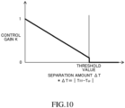
- the gain setting unit is configured to set the cancellation gain such that the cancellation gain decreases as a separation amount between the target steering torque and the driver steering torque increases, and to set the cancellation gain to 0 when the separation amount exceeds a predetermined threshold value.
- the optimal cancellation torque corresponding to strength (degree) of the steering intention of the driver can be applied.
- the gain setting unit is configured to set the cancellation gain to 0 also when a state in which the separation amount is equal to or smaller than the predetermined threshold value continues for a predetermined threshold time or longer.
- the gain setting unit is configured to set the cancellation gain to 1 when the driver steering torque changes to increase and decrease within a predetermined torque range.
- the cancellation gain is set to 1, that is, the basic cancellation torque for completely canceling the total steering torque is applied, and thus the steering angle followability of the automatic steering can reliably be increased.
- FIG. 1 is a schematic overall configuration diagram of a driving assistance device 1 according to the at least one embodiment.
- the driving assistance device 1 is mounted to a vehicle 100.
- the vehicle 100 to which the driving assistance device 1 is mounted is hereinafter also referred to as "own vehicle” to distinguish this vehicle 100 from other vehicles.
- the driving assistance device 1 includes a driving assistance ECU 10, a drive source ECU 40, a brake ECU 50, and a steering ECU 60.
- Each of the ECUs 10, 40, 50, and 60 includes a microcomputer as a principal component, and is connected for mutual transmission and reception via a controller area network (CAN) (not shown).
- CAN controller area network
- the term "ECU” is an abbreviation for "electronic control unit.”
- the microcomputer includes a CPU, a ROM, a RAM, and an interface, for example, and the CPU implements various functions by executing instructions (programs, or routines) stored in the ROM. Some or all of the ECUs 10, 40, 50, and 60 may be integrated into one ECU to serve as a controller.
- the driving assistance ECU 10 is a control device serving as a center of the execution of the driving assistance for a driver, and executes collision avoidance control in the at least one embodiment.
- the driving assistance ECU 10 is connected to a vehicle state acquisition device 20 and a periphery recognition device 30, and is configured to receive output signals and detection signals from those devices 20 and 30 each time a predetermined cycle elapses.
- the vehicle state acquisition device 20 is sensors which acquire states of the vehicle 100.
- the vehicle state acquisition device 20 includes a vehicle speed sensor 21, an accelerator sensor 22, a brake sensor 23, an inertial measurement unit (IMU) 24, and the like.
- IMU inertial measurement unit
- the vehicle speed sensor 21 detects a travel speed of the vehicle 100 (vehicle speed V).
- vehicle speed sensor 21 may be a wheel speed sensor.
- the accelerator sensor 22 detects an operation amount of an accelerator pedal (not shown) by a driver.
- the brake sensor 23 detects an operation amount of a brake pedal (not shown) by the driver.
- the IMU 24 detects an acceleration in each of a front-rear direction, a right-left direction, and an up-down direction of the vehicle 100 and an angular velocity in each of a roll direction, a pitch direction, and a yaw direction (yaw rate Yr) of the vehicle 100.
- the periphery recognition device 30 comprises sensors which acquire target information on targets around the vehicle 100.
- the periphery recognition device 30 includes a camera sensor 31, a radar sensor 32, an ultrasonic sensor 33, and the like.
- the camera sensor 31 is, for example, a stereo camera or a monocular camera, and a digital camera including an image pickup element such as a CMOS or a CCD can be used as the sensor 31.
- the camera sensor 31 captures an image of a region located on a front side and front lateral sides of the vehicle 100, and processes captured image data, to thereby recognize road surface markings.
- the road surface markings include separation lines.
- the separation lines are lines marked on a road in order to partition travel of vehicles for each direction.
- the separation line includes a solid-line separation line and a broken-line separation line.
- a region between two separation lines next to each other and extending on a vehicle road is defined as a lane.
- the camera sensor 31 calculates a shape of the lane based on the recognized separation lines. Moreover, the camera sensor calculates presence or absence of a three-dimensional object in the region located on the front side and the front lateral sides of the own vehicle 100, a type of the three-dimensional object, and a relative relationship between the own vehicle 100 and the three-dimensional object based on the captured image data.
- the type of the three-dimensional object can be determined by analyzing the image data through use of a well-known pattern matching method.
- the radar sensor 32 detects a target existing in a region located on the front side and the front lateral sides of the vehicle 100.
- the radar sensor 32 includes a millimeter wave radar or Lidar.
- the millimeter wave radar radiates a radio wave (millimeter wave) in a millimeter wave band, and receives the millimeter wave (reflected wave) reflected by a target existing within a radiation range.
- the millimeter wave radar acquires the relative distance between the vehicle 100 and the target, the relative speed between the vehicle 100 and the target, and the like based on a phase difference between the transmitted millimeter wave and the received reflected wave, an attenuation level of the reflected wave, a time from the transmission of the millimeter wave to the reception of the reflected wave, and the like.
- the Lidar sequentially scans laser light in a pulse form having a shorter wavelength than that of the millimeter wave in a plurality of directions, and receives reflected light reflected by a target, to thereby acquire a shape of the target detected in front of the vehicle 100, the relative distance between the vehicle 100 and the target, the relative speed between the vehicle 100 and the target, and the like.
- the ultrasonic sensor 33 transmits an ultrasonic wave in a pulse form within a predetermined range in a periphery of the vehicle 100, and receives a reflected wave reflected by a three-dimensional object.
- the ultrasonic sensor 33 acquires target information indicating a reflected point being a point on the three-dimensional object on which the transmitted ultrasonic wave is reflected, a distance from the ultrasonic sensor 33, and the like based on a time from the transmission to the reception of the ultrasonic wave.
- the drive source ECU 40 is connected to a drive device 41.
- the drive device 41 generates a driving force to be transmitted to driving wheels of the vehicle 100.
- an electric motor and an engine are given.
- the vehicle 100 may be any one of an engine vehicle, a hybrid vehicle (HEV), a plug-in hybrid electric vehicle (PHEV), a fuel cell electric vehicle (FCEV), and a battery electric vehicle (BEV).
- the drive source ECU 40 sets a driver-requested driving torque based on an accelerator pedal operation amount acquired by the accelerator sensor 22 and the like, and controls the operation of the drive device 41 such that the drive device 41 outputs the driver-requested driving torque.
- the brake ECU 50 is connected to a brake actuator 51.
- the brake actuator 51 is provided in a hydraulic circuit between a master cylinder (not shown) which pressurizes a hydraulic fluid through use of a stepping force on the brake pedal and a brake mechanism 52 provided to each wheel.
- the brake mechanism 52 includes a brake disc 52a fixed to the wheel and a brake caliper 52b fixed to a vehicle body.
- the brake mechanism 52 is not limited to the disc-type brake, and may be another brake mechanism such as a drum-type brake which applies a braking force to the wheel of the vehicle 100.
- the brake actuator 51 adjusts a hydraulic pressure of the fluid supplied to a wheel cylinder integrated into the brake caliper 52b in response to an instruction from the brake ECU 50, and operates the wheel cylinder through this hydraulic pressure. As a result, the brake actuator 51 presses brake pads against the brake disc 52a, to thereby generate a frictional braking force.
- the brake ECU 50 can control a braking force of the vehicle 100 by controlling the brake actuator 51.
- the steering ECU 60 is connected to a motor driver 61.
- the motor driver 61 is connected to a steering motor 62.
- the steering motor 62 is built into a steering device 63 including a steering wheel SW, a steering shaft SF, and the like.
- the steering device 63 may be any one of a rack-and-pinion type and a steer-by-wire type.
- the steering motor 62 generates a steering torque through use of electric power supplied from the motor driver 61.
- Right and left steered wheels of the vehicle 100 can be steered though use of this steering torque. That is, the steering motor 62 can change a steering angle of the vehicle 100 (steering angle of the steered wheels).
- the steering ECU 60 is connected to a steering angle sensor 64 and a steering torque sensor 65.
- the steering angle sensor 64 detects a rotation angle of the steering wheel SW or the steering shaft SF, that is, an actual steering angle ⁇ s.
- the steering torque sensor 65 detects a rotational torque of the steering wheel SW or the steering shaft SF, that is, a driver steering torque Tdr.
- the driver steering torque Tdr as used herein is a concept including both of a steering torque generated when the driver rotates the steering wheel SW and a steering holding torque generated when the driver holds the steering wheel SW.
- the actual steering angle ⁇ s and the driver steering torque Tdr take positive values when the steering wheel SW is rotated toward the left direction from a predetermined reference position (neutral position), and take negative values when the steering wheel SW is rotated toward the right direction from the predetermined reference position.
- the neutral position is a reference position at which the actual steering angle ⁇ s is substantially zero, and is a position of the steering wheel SW at the time when the vehicle 100 travels substantially straight.
- the steering ECU 60 controls the drive of the steering motor 62 based on the actual steering angle ⁇ s detected by the steering angle sensor 64, the actual steering torque Tq detected by the steering torque sensor 65, and the vehicle speed V detected by the vehicle speed sensor 21.
- the steering ECU 60 can apply an assist torque for assisting in a steering operation of the driver to the steering device 63 through use of the drive of this steering motor 62.
- the steering ECU 60 when the steering ECU 60 receives a steering command from the driving assistance ECU 10 during the execution of the collision avoidance control, the steering ECU 60 drives the steering motor 62 via the motor driver 61 based on a target steering torque specified by this steering command. As a result, the steering ECU 60 generates the steering torque such that the steering torque matches the target steering torque. This steering torque is different from the above-mentioned assist torque, and is a torque applied to the steering device 63 based on the steering command from the driving assistance ECU 10.
- the driving assistance ECU 10 can automatically change the steering angle of the steered wheels of the vehicle 100 via the steering ECU 60 without requiring the steering operation of the driver during the execution of the collision avoidance control.
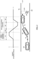
- the collision avoidance control refers to control of automatically steering the steered wheels of the own vehicle 100 such that the own vehicle 100 avoids the collision with the obstacle OB without deviating from the traveling lane LA1.
- the automatic steering as used herein is a concept including steering assistance of assisting in the steering operation of the driver such that the own vehicle 100 avoids the collision with the obstacle OB.
- the driving assistance ECU 10 executes, as the collision avoidance control, "first steering control” for avoiding the collision with the obstacle OB, and then executes “second steering control” for maintaining the own vehicle 100 within the traveling lane LA1.
- first steering control "first incremental steering” (see a section S1) of incrementing the steering angle from, for example, a neutral position (state in which the steering angle is substantially 0).
- first decremental steering (see a section S2) of returning the steering angle incremented through the first steering control to the neutral position
- second incremental steering (see a section S3) of incrementing the steering angle from the neutral position toward an opposite direction of the steering direction of the first steering control
- second decremental steering (see a section S4) of again returning the steering to the neutral position.
- FIG. 3 is a control block diagram of the driving assistance ECU 10 which executes the collision avoidance control.
- the driving assistance ECU 10 includes, as a part of function elements, a three-dimensional object information acquisition unit 11A, an obstacle determination unit 11B, a collision determination unit 11C, a target trajectory setting unit 11D, a target steering angle calculation unit 12, an FF control amount calculation unit 13, an FB control amount calculation unit 14, a subtraction unit 15, an assist torque calculation unit 16, a cancellation torque calculation unit 17, and an addition unit 18.
- Those functional elements are included in the driving assistance ECU 10 which is integrated hardware in this description, but any part thereof may be provided to another ECU independent of the driving assistance ECU 10.
- all or a part of the functional elements of the driving assistance ECU 10 may be provided in an information processing device installed at a facility (for example, a control center) which can communicate to and from the own vehicle 100.
- the three-dimensional object information acquisition unit 11A recognizes, based on position information on a left white line WL and a right white line WR (see FIG. 2 ) transmitted from the periphery recognition device 30, the traveling lane LA1 partitioned by the left white line WL and the right white line WR. Moreover, the three-dimensional object information acquisition unit 11A determines whether or not three-dimensional objects exist in the region located on the front side and the front lateral sides of the own vehicle 100 based on the target information transmitted from the periphery recognition device 30. When the three-dimensional object information acquisition unit 11A determines that three-dimensional objects exist, the three-dimensional object information acquisition unit 11A generates information on all of the three-dimensional objects determined to exist.
- the three-dimensional object information acquisition unit 11A uses a coordinate system which has a center position at a front end of the own vehicle 100 as an origin, and extends from this origin toward the right direction and the left direction and the front side to generate coordinate information on the three-dimensional objects including position coordinates of each three-dimensional object.
- the obstacle determination unit 11B determines whether or not each of all of the three-dimensional objects acquired by the three-dimensional object information acquisition unit 11A is an obstacle OB which is likely to collide with the own vehicle 100. Specifically, the obstacle determination unit 11B calculates a trajectory of the own vehicle 100 based on the vehicle speed V detected by the vehicle speed sensor 21, the yaw rate Yr detected by the IMU 24, and the actual steering angle ⁇ s detected by the steering angle sensor 64.
- the obstacle determination unit 11B calculates a trajectory of each three-dimensional object based on the coordinate information on each three-dimensional object.
- the obstacle determination unit 11B determines whether or not the own vehicle 100 is likely to collide with any one of the three-dimensional objects when the own vehicle 100 travels while maintaining a current travel state and each three-dimensional object moves while maintaining a current movement state based on the trajectory of the own vehicle 100 and the trajectory of each three-dimensional object.
- the driving assistance ECU 10 executes this determination processing based on the trajectory of the own vehicle 100 and the current position of the three-dimensional object.
- the obstacle determination unit 11B determines that this three-dimensional object is an obstacle OB.
- the collision determination unit 11C calculates, when the obstacle determination unit 11B determines that the three-dimensional object is an obstacle OB, an estimated time to the collision of the own vehicle 100 with the obstacle OB (time to collision, hereinafter referred to as "TTC") based on a distance L from the vehicle 100 to the obstacle OB and a relative speed Vr of the own vehicle 100 with respect to the obstacle OB.
- TTC time to collision
- the TTC is an index value which indicates a possibility of the collision of the own vehicle 100 with the obstacle OB.
- the target trajectory setting unit 11D calculates, when the collision determination unit 11C determines that the own vehicle 100 is highly likely to collide with the obstacle OB, a trajectory which enables the vehicle 100 to avoid the collision with the obstacle OB without interfering therewith through use of a well-known method, and sets the calculated trajectory as a target trajectory Rt (see FIG. 2 ) (see, for example, Japanese Patent Application Laid-open No. 2017-43262 and Japanese Patent Application Laid-open No. 2018-106230 ).
- the target trajectory Rt is generated, based on the target information on the obstacle OB and the position of each of the left and right white lines WL and WR, such that the target trajectory Rt passes through a collision avoidance space SP1 set on any one of the left side and the right side of the obstacle OB and is within a range in which the own vehicle 100 does not deviate from the traveling lane LA1.
- the target trajectory Rt is set so that the target trajectory Rt is formed of a first steering section S1 in which the first steering control for avoiding the collision between the vehicle 100 and the obstacle OB is executed and a second steering section S2 to a fourth steering section S4 in which the second steering control for maintaining the own vehicle 100 within the traveling lane LA1 is executed.
- the first steering section S1 the first incremental steering of the first steering control is executed.
- the second steering section S2 the first decremental steering of the second steering control is executed.
- the third steering section S3 the second incremental steering of the second steering control is executed.
- the fourth steering section S4 the second decremental steering of the second steering control is executed.
- the target steering angle calculation unit 12 calculates, when the target trajectory Rt is set by the target trajectory setting unit 11D, the target steering angle ⁇ t which achieves the target yaw rate based on the current vehicle speed V of the own vehicle 100 and a target yaw rate required to cause the own vehicle 100 to travel along the target trajectory Rt.
- the target steering angle calculation unit 12 transmits the calculated target steering angle ⁇ t to the FF control amount calculation unit 13 and the subtraction unit 15.
- the FF control amount calculation unit 13 calculates, based on the target steering angle ⁇ t, an FF target steering torque T FF which is a feedforward control amount.
- the FF target steering torque T FF is a torque control amount required to cause the own vehicle 100 to travel along the target trajectory Rt under a state in which the driver steering torque Tdr caused by the holding operation or the steering operation of the driver is not generated.
- the FF control amount calculation unit 13 refers to an FF torque map (not shown) stored in advance based on the target steering angle ⁇ t, to thereby calculate the FF target steering torque T FF .
- the FF torque map is set such that as the target steering angle ⁇ t increases, the FF target steering torque T FF increases.
- the calculation of the FF target steering torque T FF is not limited to the method which uses the map, and may be performed based on a calculation equation.
- the FF control amount calculation unit 13 transmits the calculated FF target steering torque T FF to the addition unit 18.
- the subtraction unit 15 calculates, based on the target steering angle ⁇ t transmitted from the target steering angle calculation unit 12 and the actual steering angle ⁇ s detected by the steering angle sensor 64, a deviation ⁇ between the target steering angle ⁇ t and the actual steering angle ⁇ s.
- the subtraction unit 15 transmits the calculated deviation ⁇ to the FB control amount calculation unit 14.
- the FB control amount calculation unit 14 calculates, based on the deviation ⁇ , an FB target steering torque T FB which is a feedback control amount.
- the FB control amount calculation unit 14 uses, for example, a PID control equation, a PI control equation, and a P control equation, each of which includes the deviation ⁇ as a proportional term, to calculate the FB target steering torque T FB .
- the FB control amount calculation unit 14 transmits the calculated FB target steering torque T FB to the subtraction unit 15.
- the assist torque calculation unit 16 calculates an assist torque T AS being an assist control amount for assisting in the steering operation of the driver.
- the assist torque calculation unit 16 refers to, for example, an assist torque map (not shown) stored in advance based on the driver steering torque Tdr and the vehicle speed V, to thereby calculate the assist torque T AS . It is only required to acquire the driver steering torque Tdr based on the detection result of the steering torque sensor 65 and acquire the vehicle speed V based on the detection result of the vehicle speed sensor 21. It is preferred that the assist torque map be set such that the assist torque T AS (absolute value) increases as the driver steering torque Tdr (absolute value) increases, and that the assist torque T AS (absolute value) increases as the vehicle speed V decreases.
- the calculation of the assist torque T AS is not limited to the method which uses the map, and may be calculated based on a calculation equation.
- the assist torque calculation unit 16 transmits the calculated assist torque T AS to the cancellation torque calculation unit 17 and the steering ECU 60.
- the steering ECU 60 receives the assist torque T AS from the assist torque calculation unit 16, the steering torque ECU 60 controls a current supplied to the steering motor 62 such that the torque generated by the steering motor 62 matches the assist torque T AS .
- the cancellation torque calculation unit 17 calculates a cancellation torque T CA to be applied to cancel the driver steering torque Tdr and the assist torque T AS during the execution of the collision avoidance control.
- the cancellation torque calculation unit 17 includes a basic cancellation torque calculation unit 17A, a gain setting unit 17B, and a multiplication unit 17C.
- the driver steering torque Tdr as used herein is a concept including both of the steering torque generated when the driver executes the steering operation on the steering wheel SW and the steering holding torque generated when the driver holds the steering wheel SW. It is only required to acquire the driver steering torque Tdr based on the detection result of the steering torque sensor 65.
- the basic cancellation torque calculation unit 17A inverts the signs of the total value of the driver steering torque Tdr and the assist torque T AS , to thereby calculate the basic cancellation torque T CA1 . That is, when the driver total torque T SUM is a positive value (left turn direction), the basic cancellation torque T CA1 is a negative value (right turn direction). When the driver total torque T SUM is a negative value (right turn direction), the basic cancellation torque T CA1 is a positive value (left turn direction). The basic cancellation torque calculation unit 17A transmits the calculated basic cancellation torque T CA1 to the multiplication unit 17C.
- the gain setting unit 17B sets a control gain K corresponding to a cancellation rate for canceling the driver total torque T SUM .
- the gain setting unit 17B sets the control gain K in a range of from “0" to "1.” Details of the setting of the control gain K are described later.
- the gain setting unit 17B transmits the set control gain K to the multiplication unit 17C.
- T FF +T FB +T CA +T AS a value obtained by adding the automatic steering torque control amount Tc to the assist torque T AS .
- FIG. 4A to FIG. 4C and FIG. 5A to FIG. 5C a case in which the cancellation torque T CA is applied during the execution of the collision avoidance control and a case in which the cancellation torque T CA is not applied during the execution of the collision avoidance control are compared with each other.
- FIG. 4A to FIG. 4C are diagrams of an example in the at least one embodiment in which the cancellation torque T CA is applied.
- FIG. 5A to FIG. 5C are diagrams in a comparative example in which the cancellation torque T CA is not applied.
- the own vehicle 100 avoids the collision with the obstacle OB through left turn steering.
- the signs of the steering angle and the steering torque are inverted. Thus, description of the right turn steering is omitted below.
- the driver total torque T SUM obtained by summing the driver steering holding torque generated through the holding operation of the driver and the assist torque corresponding to the driver steering holding torque is applied to the steered wheels of the vehicle 100 as indicated by a broken line of FIG. 5A .
- This driver total torque T SUM acts toward a direction opposite to that of the control torque through the automatic steering of the collision avoidance control.
- the driver total torque T SUM is a negative value opposite to the FF target steering torque T FF in the first steering control (section S1) and the first decremental steering of the second steering control (section S2), and is a positive value opposite to the FF target steering torque T FF in the second incremental steering (section S3) and the second decremental steering (section S4) of the second steering control.
- a combined torque T TAL absolute value obtained by combining the driver total torque T SUM and the FF target steering torque T FF with each other, which is indicated by a one-dot chain line of FIG. 5A , is lower than the FF target steering torque T FF (absolute value). That is, as indicated by a one-dot chain line of FIG. 5B , deterioration in steering angle followability in which the actual steering angle ⁇ s separates from the target steering angle ⁇ t is caused. As a result, there occurs a possibility that the collision between the own vehicle 100 and the obstacle OB cannot be avoided in the first steering control, and there occurs a possibility that the own vehicle 100 cannot reliably be maintained within the traveling lane LA1 in the second steering control.
- FIG. 4A to FIG. 4C show the at least one embodiment in which the cancellation torque T CA is applied.
- the control gain K is set to "1," that is, the cancellation rate is set to 100%.
- the driving assistance ECU 10 applies the basic cancellation torque T CA1 (see two-dot chain line of FIG. 4A to FIG. 4C ) for completely canceling the driver total torque T SUM during the execution of the collision avoidance control.
- the basic cancellation torque T CA1 having a positive value in a direction opposite to the driver total torque T SUM is added to the FF target steering torque T FF in the first steering control (section S1) and the first decremental steering (section S2) of the second steering control.
- the basic cancellation torque T CA1 having a negative value in a direction opposite to the driver total torque T SUM is added to the FF target steering torque T FF in the second incremental steering (section S3) and the second decremental steering (section S4) of the second steering control.
- the combined torque T TAL absolute value obtained by combining the driver total torque T SUM , the FF target steering torque T FF , and the basic cancellation torque T CA1 , which is indicated by a one-dot chain line of FIG. 4A , substantially matches the FF target steering torque T FF (absolute value). That is, as indicated by a broken line of FIG. 4B , such an increase in steering angle followability that the actual steering angle ⁇ s substantially matches the target steering angle ⁇ t is achieved. As a result, the collision between the own vehicle 100 and the obstacle OB can reliably be avoided in the first steering control, and the own vehicle 100 can reliably be maintained within the traveling lane LA1 in the second steering control.
- the control gain K is uniformly set to "1," that is, the cancellation rate is uniformly set to 100%
- the steering operation of the driver is greatly interfered with when the driver has steering intention to operate the steering wheel SW.
- the gain setting unit 17B illustrated in FIG. 3
- the gain setting unit 17B in the at least one embodiment appropriately sets the control gain K to a small value.
- a gain setting map M of FIG. 6 is stored in advance in a memory of the driving assistance ECU 10.
- the control gain K is defined on a vertical axis
- the driver steering torque Tdr is defined on a horizontal axis.
- the gain setting unit 17B refers to the gain setting map M based on the driver steering torque Tdr detected by the steering torque sensor 65, to thereby set the control gain K corresponding to the driver steering torque Tdr.
- a first threshold torque Tth1 and a second threshold torque Tth2 for determining whether or not the steering intention of the driver exists are set. It is only required to set the first threshold torque Tth1 and the second threshold torque Tth2 by executing experiments, simulation, or the like in advance.
- the first threshold torque Tth1 is set in advance with the maximum value of the steering torque at the time when the driver aimlessly holds the steering wheel SW as a reference.
- the steering angle followability of the automatic steering can reliably be increased.
- the second threshold torque Tth2 is set in advance with the minimum value of the steering torque at the time when the driver intentionally operates the steering wheel SW as a reference.
- the second threshold torque Tth2 is a value larger than the first threshold torque Tth1 (Tth2>Tth1).
- Tdr the driver steering torque
- Tth2 the second threshold torque Tth2
- the control gain K is set to "0" (cancellation rate: 0%). That is, when the driver intentionally executes the steering operation during the execution of the collision avoidance control, the cancellation torque T CA for canceling the driver total torque T SUM is set to "0."
- the driver has the steering intention, it is possible to effectively prevent the steering operation of the driver from being interfered with.
- the driver may intentionally execute the steering operation, or the driver may aimlessly hold the steering wheel SW.
- the control gain K is set such that the control gain K approaches "0" as the driver steering torque Tdr approaches from the first threshold torque Tth1 to the second threshold torque Tth2. That is, the control gain K is set such that the control gain K decreases as the driver steering torque Tdr increases.
- the gain K is caused to transition from "1" to "0,” that is, gradually reduced as the driver steering torque Tdr increases, thereby being capable of effectively preventing the steering operation of the driver from being greatly interfered with while the decrease in steering angle followability of the automatic steering is suppressed.
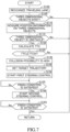
- the driving assistance ECU 10 repeatedly executes processing steps of Step S100 and subsequent steps of FIG. 7 at a predetermined cycle during the travel of the vehicle 100.
- Step S100 the driving assistance ECU 10 recognizes the traveling lane LA1 partitioned by the left white line WL and the right white line WR based on the position information on the left white line WL and the right white line WR transmitted from the periphery recognition device 30.
- Step S105 the driving assistance ECU 10 determines whether or not three-dimensional objects exist in the region located on the front side and the front lateral sides of the own vehicle 100 based on the target information transmitted from the periphery recognition device 30.
- the driving assistance ECU 10 advances the process to Step S110.
- the driving assistance ECU 10 temporarily finishes this routine (returns).
- Step S110 the driving assistance ECU 10 acquires the position information on the three-dimensional objects.
- Step S115 the driving assistance ECU 10 determines whether or not each three-dimensional object is an obstacle OB which is likely to collide with the own vehicle 100.
- the driving assistance ECU 10 determines that this three-dimensional object is an obstacle OB.
- the driving assistance ECU 10 advances the process to Step S120. Meanwhile, when the driving assistance ECU 10 determines that the three-dimensional object is not an obstacle OB (No), the driving assistance ECU 10 temporarily finishes this routine (returns).
- Step S120 the driving assistance ECU 10 calculates the TTC.
- Step S125 the driving assistance ECU 10 determines whether or not the TTC is equal to or shorter than the predetermined collision determination threshold value TTCth.
- the driving assistance ECU 10 advances the process to Step S130.
- the driving assistance ECU 10 temporarily finishes this routine (returns).
- Step S130 the driving assistance ECU 10 determines that the own vehicle 100 is highly likely to collide with the obstacle OB. After that, in Step S140, the driving assistance ECU 10 sets the target trajectory Rt which enables the own vehicle 100 to avoid the collision with the obstacle OB without deviating from the traveling lane LA1, and advances the process to Step S150.
- the driving assistance ECU 10 cannot set the target trajectory Rt, it is only required for the driving assistance ECU 10 to execute the collision avoidance control through braking control, which is not described in detail.
- Step S150 the driving assistance ECU 10 starts the automatic steering through the collision avoidance control. Specifically, the driving assistance ECU 10 starts the first steering control of executing the first incremental steering which increases the steering angle of the own vehicle 100 such that the own vehicle 100 avoids the obstacle OB while traveling along the target trajectory Rt.
- Step S155 when the finish condition for the first steering control is satisfied, the driving assistance ECU 10 advances the process to Step S160. It is only required to set a point at which the steering angle starts to gradually decrease from the maximum value as an end point of the first steering control based on, for example, a profile of the steering angle obtained from the FF target steering torque T FF .
- Step S160 the driving assistance ECU 10 starts the second steering control of increasing and decreasing the steering angle of the own vehicle 100 such that the own vehicle 100 is maintained within the traveling lane LA1 while traveling along the target trajectory Rt.
- the first decremental steering of returning the steering angle incremented through the first steering control to the neutral position the second incremental steering of incrementing the steering angle from the neutral position toward the opposite direction of the steering direction of the first steering control, and the second decremental steering of returning again the steering angle to the neutral position are successively executed.
- Step S165 when the finish condition for the second steering control is satisfied, the driving assistance ECU 10 temporarily finishes this routine (returns). It is only required that the second steering control be finished, for example, when the yaw angle of the vehicle 100 is substantially parallel with the traveling lane LA1 (white lines WL and WR) or when the actual steering angle ⁇ s falls within a desired angle range.
- the driving assistance ECU 10 repeatedly executes the cancellation torque control of FIG. 8 in parallel with the routine of FIG. 7 during the travel of the vehicle 100.
- Step S200 the driving assistance ECU 10 determines whether or not the first steering control has been started.
- the driving assistance ECU 10 advances the process to Step S210.
- the driving assistance ECU 10 temporarily finishes this routine (returns).
- Step S210 the driving assistance ECU 10 determines whether or not the driver steering torque Tdr detected by the steering torque sensor 65 is equal to or lower than the first threshold torque Tth1.
- the driving assistance ECU 10 advances the process to Step S230.
- Step S230 the driving assistance ECU 10 determines whether or not the driver steering torque Tdr detected by the steering torque sensor 65 is equal to or higher than the second threshold torque Tth2.
- the driving assistance ECU 10 advances the process to Step S240, and sets the control gain K to "0.” That is, the driving assistance ECU 10 does not apply the cancellation torque T CA .
- the driving assistance ECU 10 advances the process to Step S250.
- Step S250 the driving assistance ECU 10 sets the control gain K such that the control gain K decreases as the driver steering torque Tdr increases within the range in which the control gain K is larger than "0" and smaller than "1" (0 ⁇ K ⁇ 1). That is, the driving assistance ECU 10 gradually reduces the control gain K as the driver steering torque Tdr increases. As a result, it is possible to effectively prevent the steering operation of the driver from being greatly interfered with while the decrease in steering angle followability of the automatic steering is suppressed.
- Step S220 Step S240, or Step S250 to Step S260
- the driving assistance ECU 10 determines whether or not the second steering control has been finished.
- the driving assistance ECU 10 temporarily finishes this routine (returns).
- the driving assistance ECU 10 returns the process to the determination of Step S210. That is, until the automatic steering through the collision avoidance control is finished, the driving assistance ECU 10 repeatedly executes the processing steps of Step S210 to Step S260 described above.
- the driving assistance ECU 10 in the at least one embodiment sets, when an obstacle OB which is highly likely to collide with the own vehicle 100 is detected in the region located on the front side and the front lateral sides of the own vehicle 100, the target trajectory Rt which enables the own vehicle 100 to avoid the collision with the obstacle OB without deviating from the traveling lane LA1, and executes the automatic steering of controlling the steering angle of the steered wheels of the own vehicle 100 such that the own vehicle 100 travels along the target trajectory Rt.
- the driving assistance ECU 10 successively executes, as the automatic steering, the first steering control for avoiding the collision between the own vehicle 100 and the obstacle OB and the second steering control for preventing the own vehicle 100 from deviating from the traveling lane LA1.
- T CA driver total torque
- control gain K When the control gain K is to be gradually reduced from “1" to "0,” it is preferred to set a gradual reduction time (see the time t2 to a time t3) in which a reduction amount of the control gain K per unit time is limited in order to prevent a sudden change in driver steering torque Tdr. It is only required to set the gradual reduction time such that the gradual reduction time becomes longer as the driver steering torque Tdr increases.
- a combination of the threshold torque Tth and the threshold time Sth is not limited to one pattern, and a plurality of patterns may be set, such as a pattern in which the threshold time Sth is short when the threshold torque Tth is high, and the threshold time Sth is long when the threshold torque Tth is low.
- the driving assistance ECU 10 may determine that the driver has the steering intention, and may gradually reduce the control gain K to "0." In this case, when the control gain K is to be gradually reduced to "0," as in Modification Example 1 described above, it is preferred to set the gradual reduction time in which the reduction amount of the control gain K per unit time is limited in order to prevent the sudden change in driver steering torque Tdr.
- the state in which the driver aimlessly holds the steering wheel SW can be determined also based on a periodic change (fluctuation) in driver steering torque Tdr.
- a periodic change (fluctuation) in driver steering torque Tdr As shown in FIG. 11 , when the driver steering torque Tdr detected by the steering torque sensor 65 repeatedly changes to increase and decrease within a predetermined torque range of from T1 to T2, it is estimated that the direction of the steering of the driver is not determined. In this case, the driving assistance ECU 10 determines that the driver aimlessly holds the steering wheel SW, and maintains the setting of the control gain K at "1."
- the presence or absence of the steering intention of the driver and the like are determined based on the driver steering torque Tdr detected by the steering torque sensor 65.
- the steering torque sensor 65 detects a high reverse torque which is in the opposite direction of that of the FF target steering torque T FF generated through steering inertia and the holding operation of the driver immediately after a start of the automatic steering (first steering control) through the collision avoidance control.
- an erroneous determination may be caused.
- the driving assistance ECU 10 does not make the determination based on the detection result of the steering torque sensor 65 until a predetermined time has elapsed since the start of the first steering control. Specifically, the driving assistance ECU 10 executes the processing step of Step 205 of determining whether or not the elapsed time since the start of the first steering control has reached the predetermined time between Step S200 and Step S210 of the flow of FIG. 8 in the at least one embodiment. In this case, when the elapsed time has reached the predetermined time, it is only required to advance the process to Step S210.
- the driving assistance ECU 10 starts the determination of whether or not the driver steering torque Tdr is equal to or higher than the predetermined threshold torque Tth when the predetermined time has elapsed since the start of the first steering control. Further, in Modification Example 2 and Modification Example 3 described above, the driving assistance ECU 10 calculates the separation amount ⁇ T between the FF target steering torque T FF and the driver steering torque Tdr when the predetermined time has elapsed since the start of the first steering control.
- the driving assistance ECU 10 starts the determination of whether or not the driver steering torque Tdr is changing to increase and decrease within the predetermined torque range of from T1 to T2 when the predetermined time has elapsed since the start of the first steering control. As described above, it is possible to effectively prevent the erroneous determination based on the reverse torque by starting the determination when the predetermined time has elapsed since the start of the first steering control.
Landscapes
- Engineering & Computer Science (AREA)
- Transportation (AREA)
- Mechanical Engineering (AREA)
- Chemical & Material Sciences (AREA)
- Combustion & Propulsion (AREA)
- Automation & Control Theory (AREA)
- Physics & Mathematics (AREA)
- Mathematical Physics (AREA)
- Human Computer Interaction (AREA)
- Steering Control In Accordance With Driving Conditions (AREA)
- Control Of Driving Devices And Active Controlling Of Vehicle (AREA)
Abstract
To increase steering angle followability of automatic steering, it is provided a driving assistance device (1) for executing collision avoidance control of controlling a steering angle (θs) of an own vehicle (100) such that the own vehicle (100) travels along a target trajectory (Rt) which enables the own vehicle (100) to avoid a collision with an obstacle (OB). The driving assistance device (1) includes: a setting unit configured to set a target steering angle (θt), and to set a target steering torque (Tt) for matching the steering angle (θs) with the target steering angle (θt); a cancellation unit (17) configured to set a cancellation torque (TCA) which cancels a total steering torque (TSUM) obtained by summing a driver steering torque (Tdr) and a steering assist torque (TAS) set based on the driver steering torque (Tdr); and a control unit (60) configured to execute steering control of controlling the steering angle (θs) based on a torque control amount obtained by adding the target steering torque (Tt) to the cancellation torque (TCA).
Description
- The present disclosure relates to a driving assistance device, a driving assistance method, and a program, and relates to a technology of collision avoidance control of avoiding collision between an own vehicle and an obstacle.
- For example, in
Japanese Patent Application Laid-open No. 2004-256076 - There has been known, as a driving assistance device installed in a vehicle, a device which executes, when an obstacle which is highly likely to collide with an own vehicle is detected in front of the own vehicle, collision avoidance control of automatically controlling a steering angle of the own vehicle such that the collision with the obstacle is avoided. The collision avoidance control successively executes steering control for avoiding the collision of the own vehicle with the obstacle, and then executes steering control for preventing deviation of the own vehicle from a traveling lane. In the above-mentioned collision avoidance control, in order to achieve the avoidance of the collision with the obstacle and the prevention of the deviation from the traveling lane, it is important to increase steering angle followability of the automatic steering.
- However, when the driver aimlessly holds a steering wheel during the execution of the collision avoidance control, a steering holding torque through the holding operation by the driver and an assist torque corresponding to this steering holding torque act toward an opposite direction on a control torque through the automatic steering. When this torque toward the opposite direction acts on the control torque, there is a problem in that steering angle followability of the automatic steering decreases, resulting in an insufficient steering angle and the like.
- The present disclosure has been made in order to solve the above-mentioned problem. That is, one object of the present disclosure is to effectively increase steering angle followability of automatic steering through collision avoidance control.
- According to at least one embodiment of the present disclosure, there is provided a driving assistance device for executing collision avoidance control of controlling, when an obstacle which is highly likely to collide with an own vehicle is detected in a region located on a front side and front lateral sides of the own vehicle, a steering angle of the own vehicle so that the own vehicle travels along a target trajectory which enables the own vehicle to avoid the collision with the obstacle without deviating from a traveling lane, the driving assistance device including: a target steering torque setting unit configured to set a target steering angle required to cause the own vehicle to travel along the target trajectory, and to set a target steering torque for matching a steering angle of the own vehicle with the target steering angle under a state in which a driver steering torque generated through one of a holding operation or a steering operation of a steering wheel by a driver of the own vehicle is not generated; a cancellation torque setting unit configured to set a cancellation torque being a torque in a direction of canceling a total steering torque obtained by summing the driver steering torque and a steering assist torque set based on the driver steering torque; and a steering control unit configured to execute steering control of controlling the steering angle of the own vehicle based on a torque control amount obtained by adding the target steering torque to the cancellation torque.
- According to at least one embodiment of the present disclosure, there is provided a driving assistance method of executing collision avoidance control of controlling, when an obstacle which is highly likely to collide with an own vehicle is detected in a region located on a front side and front lateral sides of the own vehicle, a steering angle of the own vehicle so that the own vehicle travels along a target trajectory which enables the own vehicle to avoid the collision with the obstacle without deviating from a traveling lane, the driving assistance method including: setting a target steering angle required to cause the own vehicle to travel along the target trajectory, and setting a target steering torque for matching a steering angle of the own vehicle with the target steering angle under a state in which a driver steering torque generated through one of a holding operation or a steering operation of a steering wheel by a driver of the own vehicle is not generated; setting a cancellation torque being a torque in a direction of canceling a total steering torque obtained by summing the driver steering torque and a steering assist torque set based on the driver steering torque; and executing steering control of controlling the steering angle of the own vehicle based on a torque control amount obtained by adding the target steering torque to the cancellation torque.
- According to at least one embodiment of the present disclosure, there is provided a program for causing a computer of a driving assistance device for executing collision avoidance control of controlling, when an obstacle which is highly likely to collide with an own vehicle is detected in a region located on a front side and front lateral sides of the own vehicle, a steering angle of the own vehicle so that the own vehicle travels along a target trajectory which enables the own vehicle to avoid the collision with the obstacle without deviating from a traveling lane, to execute the processes of: setting a target steering angle required to cause the own vehicle to travel along the target trajectory, and setting a target steering torque for matching a steering angle of the own vehicle with the target steering angle under a state in which a driver steering torque generated through one of a holding operation or a steering operation of a steering wheel by a driver of the own vehicle is not generated; setting a cancellation torque being a torque in a direction of canceling a total steering torque obtained by summing the driver steering torque and a steering assist torque set based on the driver steering torque; and executing steering control of controlling the steering angle of the own vehicle based on a torque control amount obtained by adding the target steering torque to the cancellation torque.
- With the above-mentioned configuration, during the execution of the automatic steering, the driving assistance ECU applies the cancellation torque for canceling the driver total torque obtained by summing the driver steering torque generated through the holding operation or the steering operation of the driver and the assist torque generated in accordance with the driver steering torque. As a result, an insufficient steering angle of the actual steering angle with respect to the target steering angle which is caused by the driver total torque during the execution of the automatic steering is suppressed, and hence steering angle followability can be increased.
- In another aspect of the present disclosure, the cancellation torque setting unit includes: a basic cancellation torque setting unit configured to set a basic cancellation torque for completely canceling the total steering torque ; and a gain setting unit configured to set a cancellation gain corresponding to a magnitude of the driver steering torque, and the cancellation torque setting unit is configured to set the cancellation torque by multiplying the basic cancellation torque by the cancellation gain.
- According to this aspect, the optimal cancellation torque corresponding to a magnitude of the driver steering torque can be applied.
- In another aspect of the present disclosure, the gain setting unit is configured to set the cancellation gain such that the cancellation gain decreases as the driver steering torque increases.
- According to this aspect, it is possible to effectively prevent the steering operation of the driver from being interfered with when the driver has steering intention to execute the steering operation.
- In another aspect of the present disclosure, the gain setting unit is configured to set the cancellation gain to 0 when a state in which the driver steering torque is equal to or higher than a predetermined threshold torque continues for a predetermined threshold time or longer.
- According to this aspect, it is possible to reliably prevent the steering operation of the driver from being interfered with when the driver clearly has steering intention to execute the steering operation.
- In another aspect of the present disclosure, the gain setting unit is configured to set the cancellation gain such that the cancellation gain decreases as a separation amount between the target steering torque and the driver steering torque increases, and to set the cancellation gain to 0 when the separation amount exceeds a predetermined threshold value.
- According to this aspect, the optimal cancellation torque corresponding to strength (degree) of the steering intention of the driver can be applied.
- The gain setting unit is configured to set the cancellation gain to 0 also when a state in which the separation amount is equal to or smaller than the predetermined threshold value continues for a predetermined threshold time or longer.
- According to this aspect, it is possible to effectively prevent the steering operation of the driver from being interfered with after the steering intention of the driver becomes clear.
- The gain setting unit is configured to set the cancellation gain to 1 when the driver steering torque changes to increase and decrease within a predetermined torque range.
- According to this aspect, in a case in which the driver aimlessly holds the steering wheel, the cancellation gain is set to 1, that is, the basic cancellation torque for completely canceling the total steering torque is applied, and thus the steering angle followability of the automatic steering can reliably be increased.
- In order to facilitate the understanding of the invention, in the above description, the constituent features of the invention corresponding to at least one embodiment of the present disclosure are suffixed in parentheses with reference symbols used in the at least one embodiment. However, the constituent features of the invention are not intended to be limited to those in the at least one embodiment as defined by the reference symbols.
-
-
FIG. 1 is a schematic overall configuration diagram of a driving assistance device according to at least one embodiment of the present disclosure. -
FIG. 2 is a schematic diagram for illustrating an overview of an operation of collision avoidance control in the at least one embodiment. -
FIG. 3 is a control block diagram of a driving assistance ECU in the at least one embodiment. -
FIG. 4A, FIG. 4B, and FIG. 4C are schematic diagrams for illustrating the at least one embodiment in which a cancellation torque is applied during execution of the collision avoidance control. -
FIG. 5A, FIG. 5B, and FIG. 5C are schematic diagrams for illustrating a comparative example in which the cancellation torque is not applied during the execution of the collision avoidance control. -
FIG. 6 is a schematic graph for showing an example of a gain setting map. -
FIG. 7 is a flowchart for illustrating a routine of processing of the collision avoidance control in the at least one embodiment. -
FIG. 8 is a flowchart for illustrating a routine of processing of cancellation torque control in the at least one embodiment. -
FIG. 9 is a schematic graph for showing Modification Example 1. -
FIG. 10 is a schematic graph for showing Modification Example 2. -
FIG. 11 is a schematic graph for showing Modification Example 4. - Description is now given of a driving assistance device, a driving assistance method, and a program according to at least one embodiment of the present disclosure with reference to the drawings. Like components are denoted by like reference symbols and the same applies to the names and functions of those components. Thus, a detailed description of those components is not repeated.
-
FIG. 1 is a schematic overall configuration diagram of adriving assistance device 1 according to the at least one embodiment. As illustrated inFIG. 1 , thedriving assistance device 1 is mounted to avehicle 100. Thevehicle 100 to which thedriving assistance device 1 is mounted is hereinafter also referred to as "own vehicle" to distinguish thisvehicle 100 from other vehicles. Thedriving assistance device 1 includes adriving assistance ECU 10, adrive source ECU 40, abrake ECU 50, and asteering ECU 60. Each of theECUs ECUs - The driving assistance ECU 10 is a control device serving as a center of the execution of the driving assistance for a driver, and executes collision avoidance control in the at least one embodiment. The driving
assistance ECU 10 is connected to a vehiclestate acquisition device 20 and aperiphery recognition device 30, and is configured to receive output signals and detection signals from thosedevices - The vehicle
state acquisition device 20 is sensors which acquire states of thevehicle 100. Specifically, the vehiclestate acquisition device 20 includes avehicle speed sensor 21, anaccelerator sensor 22, abrake sensor 23, an inertial measurement unit (IMU) 24, and the like. - The
vehicle speed sensor 21 detects a travel speed of the vehicle 100 (vehicle speed V). Thevehicle speed sensor 21 may be a wheel speed sensor. Theaccelerator sensor 22 detects an operation amount of an accelerator pedal (not shown) by a driver. Thebrake sensor 23 detects an operation amount of a brake pedal (not shown) by the driver. TheIMU 24 detects an acceleration in each of a front-rear direction, a right-left direction, and an up-down direction of thevehicle 100 and an angular velocity in each of a roll direction, a pitch direction, and a yaw direction (yaw rate Yr) of thevehicle 100. - The
periphery recognition device 30 comprises sensors which acquire target information on targets around thevehicle 100. Specifically, theperiphery recognition device 30 includes acamera sensor 31, aradar sensor 32, anultrasonic sensor 33, and the like. - The
camera sensor 31 is, for example, a stereo camera or a monocular camera, and a digital camera including an image pickup element such as a CMOS or a CCD can be used as thesensor 31. Thecamera sensor 31 captures an image of a region located on a front side and front lateral sides of thevehicle 100, and processes captured image data, to thereby recognize road surface markings. The road surface markings include separation lines. The separation lines are lines marked on a road in order to partition travel of vehicles for each direction. The separation line includes a solid-line separation line and a broken-line separation line. In the at least one embodiment, a region between two separation lines next to each other and extending on a vehicle road is defined as a lane. Thecamera sensor 31 calculates a shape of the lane based on the recognized separation lines. Moreover, the camera sensor calculates presence or absence of a three-dimensional object in the region located on the front side and the front lateral sides of theown vehicle 100, a type of the three-dimensional object, and a relative relationship between theown vehicle 100 and the three-dimensional object based on the captured image data. The type of the three-dimensional object can be determined by analyzing the image data through use of a well-known pattern matching method. - The
radar sensor 32 detects a target existing in a region located on the front side and the front lateral sides of thevehicle 100. Theradar sensor 32 includes a millimeter wave radar or Lidar. The millimeter wave radar radiates a radio wave (millimeter wave) in a millimeter wave band, and receives the millimeter wave (reflected wave) reflected by a target existing within a radiation range. The millimeter wave radar acquires the relative distance between thevehicle 100 and the target, the relative speed between thevehicle 100 and the target, and the like based on a phase difference between the transmitted millimeter wave and the received reflected wave, an attenuation level of the reflected wave, a time from the transmission of the millimeter wave to the reception of the reflected wave, and the like. The Lidar sequentially scans laser light in a pulse form having a shorter wavelength than that of the millimeter wave in a plurality of directions, and receives reflected light reflected by a target, to thereby acquire a shape of the target detected in front of thevehicle 100, the relative distance between thevehicle 100 and the target, the relative speed between thevehicle 100 and the target, and the like. - The
ultrasonic sensor 33 transmits an ultrasonic wave in a pulse form within a predetermined range in a periphery of thevehicle 100, and receives a reflected wave reflected by a three-dimensional object. Theultrasonic sensor 33 acquires target information indicating a reflected point being a point on the three-dimensional object on which the transmitted ultrasonic wave is reflected, a distance from theultrasonic sensor 33, and the like based on a time from the transmission to the reception of the ultrasonic wave. - The
drive source ECU 40 is connected to adrive device 41. Thedrive device 41 generates a driving force to be transmitted to driving wheels of thevehicle 100. As thedrive device 41, for example, an electric motor and an engine are given. Thevehicle 100 may be any one of an engine vehicle, a hybrid vehicle (HEV), a plug-in hybrid electric vehicle (PHEV), a fuel cell electric vehicle (FCEV), and a battery electric vehicle (BEV). Thedrive source ECU 40 sets a driver-requested driving torque based on an accelerator pedal operation amount acquired by theaccelerator sensor 22 and the like, and controls the operation of thedrive device 41 such that thedrive device 41 outputs the driver-requested driving torque. - The
brake ECU 50 is connected to abrake actuator 51. Thebrake actuator 51 is provided in a hydraulic circuit between a master cylinder (not shown) which pressurizes a hydraulic fluid through use of a stepping force on the brake pedal and abrake mechanism 52 provided to each wheel. Thebrake mechanism 52 includes abrake disc 52a fixed to the wheel and abrake caliper 52b fixed to a vehicle body. Thebrake mechanism 52 is not limited to the disc-type brake, and may be another brake mechanism such as a drum-type brake which applies a braking force to the wheel of thevehicle 100. - The
brake actuator 51 adjusts a hydraulic pressure of the fluid supplied to a wheel cylinder integrated into thebrake caliper 52b in response to an instruction from thebrake ECU 50, and operates the wheel cylinder through this hydraulic pressure. As a result, thebrake actuator 51 presses brake pads against thebrake disc 52a, to thereby generate a frictional braking force. Thus, thebrake ECU 50 can control a braking force of thevehicle 100 by controlling thebrake actuator 51. - The steering
ECU 60 is connected to amotor driver 61. Themotor driver 61 is connected to asteering motor 62. Thesteering motor 62 is built into asteering device 63 including a steering wheel SW, a steering shaft SF, and the like. Thesteering device 63 may be any one of a rack-and-pinion type and a steer-by-wire type. Thesteering motor 62 generates a steering torque through use of electric power supplied from themotor driver 61. Right and left steered wheels of thevehicle 100 can be steered though use of this steering torque. That is, thesteering motor 62 can change a steering angle of the vehicle 100 (steering angle of the steered wheels). - The steering
ECU 60 is connected to asteering angle sensor 64 and asteering torque sensor 65. Thesteering angle sensor 64 detects a rotation angle of the steering wheel SW or the steering shaft SF, that is, an actual steering angle θs. Thesteering torque sensor 65 detects a rotational torque of the steering wheel SW or the steering shaft SF, that is, a driver steering torque Tdr. The driver steering torque Tdr as used herein is a concept including both of a steering torque generated when the driver rotates the steering wheel SW and a steering holding torque generated when the driver holds the steering wheel SW. The actual steering angle θs and the driver steering torque Tdr, for example, take positive values when the steering wheel SW is rotated toward the left direction from a predetermined reference position (neutral position), and take negative values when the steering wheel SW is rotated toward the right direction from the predetermined reference position. The neutral position is a reference position at which the actual steering angle θs is substantially zero, and is a position of the steering wheel SW at the time when thevehicle 100 travels substantially straight. - The steering
ECU 60 controls the drive of thesteering motor 62 based on the actual steering angle θs detected by thesteering angle sensor 64, the actual steering torque Tq detected by thesteering torque sensor 65, and the vehicle speed V detected by thevehicle speed sensor 21. Thesteering ECU 60 can apply an assist torque for assisting in a steering operation of the driver to thesteering device 63 through use of the drive of thissteering motor 62. - Moreover, when the steering
ECU 60 receives a steering command from the drivingassistance ECU 10 during the execution of the collision avoidance control, the steeringECU 60 drives thesteering motor 62 via themotor driver 61 based on a target steering torque specified by this steering command. As a result, the steeringECU 60 generates the steering torque such that the steering torque matches the target steering torque. This steering torque is different from the above-mentioned assist torque, and is a torque applied to thesteering device 63 based on the steering command from the drivingassistance ECU 10. Thus, the drivingassistance ECU 10 can automatically change the steering angle of the steered wheels of thevehicle 100 via thesteering ECU 60 without requiring the steering operation of the driver during the execution of the collision avoidance control. - Next, referring to
FIG. 2 andFIG. 3 , an overview of an operation of the collision avoidance control is described. As illustrated inFIG. 2 , it is assumed that, when theown vehicle 100 is traveling on a traveling lane LA1, which is, for example, a straight road, there occurs a situation in which an obstacle OB, which is a three-dimensional object (target) and is highly likely to collide with theown vehicle 100, exists. In this case, the drivingassistance ECU 10 executes the collision avoidance control of avoiding the collision of theown vehicle 100 with the obstacle OB. The collision avoidance control refers to control of automatically steering the steered wheels of theown vehicle 100 such that theown vehicle 100 avoids the collision with the obstacle OB without deviating from the traveling lane LA1. The automatic steering as used herein is a concept including steering assistance of assisting in the steering operation of the driver such that theown vehicle 100 avoids the collision with the obstacle OB. - Specifically, the driving
assistance ECU 10 executes, as the collision avoidance control, "first steering control" for avoiding the collision with the obstacle OB, and then executes "second steering control" for maintaining theown vehicle 100 within the traveling lane LA1. In the first steering control, "first incremental steering" (see a section S1) of incrementing the steering angle from, for example, a neutral position (state in which the steering angle is substantially 0). In the second steering control, there are successively executed "first decremental steering (see a section S2)" of returning the steering angle incremented through the first steering control to the neutral position, "second incremental steering" (see a section S3) of incrementing the steering angle from the neutral position toward an opposite direction of the steering direction of the first steering control, and "second decremental steering" (see a section S4) of again returning the steering to the neutral position. -
FIG. 3 is a control block diagram of the drivingassistance ECU 10 which executes the collision avoidance control. The drivingassistance ECU 10 includes, as a part of function elements, a three-dimensional objectinformation acquisition unit 11A, anobstacle determination unit 11B, a collision determination unit 11C, a targettrajectory setting unit 11D, a target steeringangle calculation unit 12, an FF controlamount calculation unit 13, an FB controlamount calculation unit 14, asubtraction unit 15, an assisttorque calculation unit 16, a cancellationtorque calculation unit 17, and anaddition unit 18. Those functional elements are included in thedriving assistance ECU 10 which is integrated hardware in this description, but any part thereof may be provided to another ECU independent of the drivingassistance ECU 10. Moreover, all or a part of the functional elements of the drivingassistance ECU 10 may be provided in an information processing device installed at a facility (for example, a control center) which can communicate to and from theown vehicle 100. - The three-dimensional object
information acquisition unit 11A recognizes, based on position information on a left white line WL and a right white line WR (seeFIG. 2 ) transmitted from theperiphery recognition device 30, the traveling lane LA1 partitioned by the left white line WL and the right white line WR. Moreover, the three-dimensional objectinformation acquisition unit 11A determines whether or not three-dimensional objects exist in the region located on the front side and the front lateral sides of theown vehicle 100 based on the target information transmitted from theperiphery recognition device 30. When the three-dimensional objectinformation acquisition unit 11A determines that three-dimensional objects exist, the three-dimensional objectinformation acquisition unit 11A generates information on all of the three-dimensional objects determined to exist. Specifically, the three-dimensional objectinformation acquisition unit 11A uses a coordinate system which has a center position at a front end of theown vehicle 100 as an origin, and extends from this origin toward the right direction and the left direction and the front side to generate coordinate information on the three-dimensional objects including position coordinates of each three-dimensional object. - The
obstacle determination unit 11B determines whether or not each of all of the three-dimensional objects acquired by the three-dimensional objectinformation acquisition unit 11A is an obstacle OB which is likely to collide with theown vehicle 100. Specifically, theobstacle determination unit 11B calculates a trajectory of theown vehicle 100 based on the vehicle speed V detected by thevehicle speed sensor 21, the yaw rate Yr detected by theIMU 24, and the actual steering angle θs detected by thesteering angle sensor 64. - Moreover, the
obstacle determination unit 11B calculates a trajectory of each three-dimensional object based on the coordinate information on each three-dimensional object. Theobstacle determination unit 11B determines whether or not theown vehicle 100 is likely to collide with any one of the three-dimensional objects when theown vehicle 100 travels while maintaining a current travel state and each three-dimensional object moves while maintaining a current movement state based on the trajectory of theown vehicle 100 and the trajectory of each three-dimensional object. When the three-dimensional object is stationary, the drivingassistance ECU 10 executes this determination processing based on the trajectory of theown vehicle 100 and the current position of the three-dimensional object. When theobstacle determination unit 11B determines that theown vehicle 100 is likely to collide with the three-dimensional object based on a result of the determination, theobstacle determination unit 11B determines that this three-dimensional object is an obstacle OB. - The collision determination unit 11C calculates, when the
obstacle determination unit 11B determines that the three-dimensional object is an obstacle OB, an estimated time to the collision of theown vehicle 100 with the obstacle OB (time to collision, hereinafter referred to as "TTC") based on a distance L from thevehicle 100 to the obstacle OB and a relative speed Vr of theown vehicle 100 with respect to the obstacle OB. The TTC is an index value which indicates a possibility of the collision of theown vehicle 100 with the obstacle OB. The TTC can be obtained by dividing the distance L from theown vehicle 100 to the obstacle OB by the relative speed Vr (TTC=L/Vr). The collision determination unit 11C determines that theown vehicle 100 is highly likely to collide with the obstacle OB when the TTC is equal to or shorter than a predetermined collision determination threshold value TTCth. - The target
trajectory setting unit 11D calculates, when the collision determination unit 11C determines that theown vehicle 100 is highly likely to collide with the obstacle OB, a trajectory which enables thevehicle 100 to avoid the collision with the obstacle OB without interfering therewith through use of a well-known method, and sets the calculated trajectory as a target trajectory Rt (seeFIG. 2 ) (see, for example,Japanese Patent Application Laid-open No. 2017-43262 Japanese Patent Application Laid-open No. 2018-106230 own vehicle 100 does not deviate from the traveling lane LA1. - Specifically, as illustrated in
FIG. 2 , the target trajectory Rt is set so that the target trajectory Rt is formed of a first steering section S1 in which the first steering control for avoiding the collision between thevehicle 100 and the obstacle OB is executed and a second steering section S2 to a fourth steering section S4 in which the second steering control for maintaining theown vehicle 100 within the traveling lane LA1 is executed. In the first steering section S1, the first incremental steering of the first steering control is executed. In the second steering section S2, the first decremental steering of the second steering control is executed. In the third steering section S3, the second incremental steering of the second steering control is executed. In the fourth steering section S4, the second decremental steering of the second steering control is executed. - The target steering
angle calculation unit 12 calculates, when the target trajectory Rt is set by the targettrajectory setting unit 11D, the target steering angle θt which achieves the target yaw rate based on the current vehicle speed V of theown vehicle 100 and a target yaw rate required to cause theown vehicle 100 to travel along the target trajectory Rt. The target steeringangle calculation unit 12 transmits the calculated target steering angle θt to the FF controlamount calculation unit 13 and thesubtraction unit 15. - The FF control
amount calculation unit 13 calculates, based on the target steering angle θt, an FF target steering torque TFF which is a feedforward control amount. The FF target steering torque TFF is a torque control amount required to cause theown vehicle 100 to travel along the target trajectory Rt under a state in which the driver steering torque Tdr caused by the holding operation or the steering operation of the driver is not generated. For example, the FF controlamount calculation unit 13 refers to an FF torque map (not shown) stored in advance based on the target steering angle θt, to thereby calculate the FF target steering torque TFF. The FF torque map is set such that as the target steering angle θt increases, the FF target steering torque TFF increases. The calculation of the FF target steering torque TFF is not limited to the method which uses the map, and may be performed based on a calculation equation. The FF controlamount calculation unit 13 transmits the calculated FF target steering torque TFF to theaddition unit 18. - The
subtraction unit 15 calculates, based on the target steering angle θt transmitted from the target steeringangle calculation unit 12 and the actual steering angle θs detected by thesteering angle sensor 64, a deviation Δθ between the target steering angle θt and the actual steering angle θs. Thesubtraction unit 15 transmits the calculated deviation Δθ to the FB controlamount calculation unit 14. - The FB control
amount calculation unit 14 calculates, based on the deviation Δθ, an FB target steering torque TFB which is a feedback control amount. The FB controlamount calculation unit 14 uses, for example, a PID control equation, a PI control equation, and a P control equation, each of which includes the deviation Δθ as a proportional term, to calculate the FB target steering torque TFB. The FB controlamount calculation unit 14 transmits the calculated FB target steering torque TFB to thesubtraction unit 15. - The assist
torque calculation unit 16 calculates an assist torque TAS being an assist control amount for assisting in the steering operation of the driver. The assisttorque calculation unit 16 refers to, for example, an assist torque map (not shown) stored in advance based on the driver steering torque Tdr and the vehicle speed V, to thereby calculate the assist torque TAS. It is only required to acquire the driver steering torque Tdr based on the detection result of thesteering torque sensor 65 and acquire the vehicle speed V based on the detection result of thevehicle speed sensor 21. It is preferred that the assist torque map be set such that the assist torque TAS (absolute value) increases as the driver steering torque Tdr (absolute value) increases, and that the assist torque TAS (absolute value) increases as the vehicle speed V decreases. The calculation of the assist torque TAS is not limited to the method which uses the map, and may be calculated based on a calculation equation. The assisttorque calculation unit 16 transmits the calculated assist torque TAS to the cancellationtorque calculation unit 17 and thesteering ECU 60. When thesteering ECU 60 receives the assist torque TAS from the assisttorque calculation unit 16, thesteering torque ECU 60 controls a current supplied to thesteering motor 62 such that the torque generated by thesteering motor 62 matches the assist torque TAS. - The cancellation
torque calculation unit 17 calculates a cancellation torque TCA to be applied to cancel the driver steering torque Tdr and the assist torque TAS during the execution of the collision avoidance control. Specifically, the cancellationtorque calculation unit 17 includes a basic cancellationtorque calculation unit 17A, again setting unit 17B, and amultiplication unit 17C. - The basic cancellation
torque calculation unit 17A calculates a basic cancellation torque TCA1 (=-TSUM) being a steering torque for completely canceling a driver total torque TSUM (=Tdr+TAS) obtained by summing the driver steering torque Tdr and the assist torque TAS. The driver steering torque Tdr as used herein is a concept including both of the steering torque generated when the driver executes the steering operation on the steering wheel SW and the steering holding torque generated when the driver holds the steering wheel SW. It is only required to acquire the driver steering torque Tdr based on the detection result of thesteering torque sensor 65. - The basic cancellation
torque calculation unit 17A inverts the signs of the total value of the driver steering torque Tdr and the assist torque TAS, to thereby calculate the basic cancellation torque TCA1. That is, when the driver total torque TSUM is a positive value (left turn direction), the basic cancellation torque TCA1 is a negative value (right turn direction). When the driver total torque TSUM is a negative value (right turn direction), the basic cancellation torque TCA1 is a positive value (left turn direction). The basic cancellationtorque calculation unit 17A transmits the calculated basic cancellation torque TCA1 to themultiplication unit 17C. - The
gain setting unit 17B sets a control gain K corresponding to a cancellation rate for canceling the driver total torque TSUM. Thegain setting unit 17B sets the control gain K in a range of from "0" to "1." Details of the setting of the control gain K are described later. Thegain setting unit 17B transmits the set control gain K to themultiplication unit 17C. - The
multiplication unit 17C obtains a value (=TCA1×K) by multiplying the basic cancellation torque TCA1 transmitted from the basic cancellationtorque calculation unit 17A by the control gain K transmitted from thegain setting unit 17B, and transmits this value to theaddition unit 18 as a final cancellation torque TCA. - The
addition unit 18 adds the FB target steering torque TFB transmitted from the FB controlamount calculation unit 14 to the FF target steering torque TFF transmitted from the FF controlamount calculation unit 13, to thereby calculate a target steering torque Tt (=TFF+TFB). Moreover, theaddition unit 18 obtains an automatic steering torque control amount Tc (=TFF+TFB+TCA) being a value obtained by adding the cancellation torque TCA(=TCA1×K) transmitted from themultiplication unit 17C to the target steering torque Tt, and transmits this automatic steering torque control amount Tc to thesteering ECU 60 as a final control amount of the collision avoidance control. When thesteering ECU 60 receives the automatic steering torque control amount Tc from theaddition unit 18, the steeringECU 60 controls the current supplied to thesteering motor 62 such that the torque generated by thesteering motor 62 matches a value (=TFF+TFB+TCA+TAS) obtained by adding the automatic steering torque control amount Tc to the assist torque TAS. As a result, the automatic steering of causing theown vehicle 100 to travel along the target trajectory Rt while canceling the driver total torque TSUM during the execution of the collision avoidance control is achieved. - Now, referring to
FIG. 4A to FIG. 4C andFIG. 5A to FIG. 5C , a case in which the cancellation torque TCA is applied during the execution of the collision avoidance control and a case in which the cancellation torque TCA is not applied during the execution of the collision avoidance control are compared with each other.FIG. 4A to FIG. 4C are diagrams of an example in the at least one embodiment in which the cancellation torque TCA is applied.FIG. 5A to FIG. 5C are diagrams in a comparative example in which the cancellation torque TCA is not applied. In the examples ofFIG. 4A to FIG. 4C andFIG. 5A to FIG. 5C , theown vehicle 100 avoids the collision with the obstacle OB through left turn steering. When the collision is avoided through right turn steering, only the signs of the steering angle and the steering torque are inverted. Thus, description of the right turn steering is omitted below. - First, the comparative example of
FIG. 5A to FIG. 5C is described. When the driver aimlessly holds the steering wheel SW during the execution of the collision avoidance control, the driver total torque TSUM obtained by summing the driver steering holding torque generated through the holding operation of the driver and the assist torque corresponding to the driver steering holding torque is applied to the steered wheels of thevehicle 100 as indicated by a broken line ofFIG. 5A . This driver total torque TSUM acts toward a direction opposite to that of the control torque through the automatic steering of the collision avoidance control. That is, the driver total torque TSUM is a negative value opposite to the FF target steering torque TFF in the first steering control (section S1) and the first decremental steering of the second steering control (section S2), and is a positive value opposite to the FF target steering torque TFF in the second incremental steering (section S3) and the second decremental steering (section S4) of the second steering control. - When such a driver total torque TSUM is added during the execution of the collision avoidance control, a combined torque TTAL (absolute value) obtained by combining the driver total torque TSUM and the FF target steering torque TFF with each other, which is indicated by a one-dot chain line of
FIG. 5A , is lower than the FF target steering torque TFF (absolute value). That is, as indicated by a one-dot chain line ofFIG. 5B , deterioration in steering angle followability in which the actual steering angle θs separates from the target steering angle θt is caused. As a result, there occurs a possibility that the collision between theown vehicle 100 and the obstacle OB cannot be avoided in the first steering control, and there occurs a possibility that theown vehicle 100 cannot reliably be maintained within the traveling lane LA1 in the second steering control. -
FIG. 4A to FIG. 4C show the at least one embodiment in which the cancellation torque TCA is applied. In the example ofFIG. 4A to FIG. 4C , it is assumed that the control gain K is set to "1," that is, the cancellation rate is set to 100%. In the at least one embodiment ofFIG. 4A to FIG. 4C , the drivingassistance ECU 10 applies the basic cancellation torque TCA1 (see two-dot chain line ofFIG. 4A to FIG. 4C ) for completely canceling the driver total torque TSUM during the execution of the collision avoidance control. That is, the basic cancellation torque TCA1 having a positive value in a direction opposite to the driver total torque TSUM is added to the FF target steering torque TFF in the first steering control (section S1) and the first decremental steering (section S2) of the second steering control. The basic cancellation torque TCA1 having a negative value in a direction opposite to the driver total torque TSUM is added to the FF target steering torque TFF in the second incremental steering (section S3) and the second decremental steering (section S4) of the second steering control. - When such a basic cancellation torque TCA1 is added to the FF target steering torque TFF, the combined torque TTAL (absolute value) obtained by combining the driver total torque TSUM, the FF target steering torque TFF, and the basic cancellation torque TCA1, which is indicated by a one-dot chain line of
FIG. 4A , substantially matches the FF target steering torque TFF (absolute value). That is, as indicated by a broken line ofFIG. 4B , such an increase in steering angle followability that the actual steering angle θs substantially matches the target steering angle θt is achieved. As a result, the collision between theown vehicle 100 and the obstacle OB can reliably be avoided in the first steering control, and theown vehicle 100 can reliably be maintained within the traveling lane LA1 in the second steering control. - In this case, when the control gain K is uniformly set to "1," that is, the cancellation rate is uniformly set to 100%, the steering operation of the driver is greatly interfered with when the driver has steering intention to operate the steering wheel SW. As a result, there is a fear in that a dangerous behavior of the
vehicle 100 is caused. Thus, when steering intervention of the driver is detected, thegain setting unit 17B (illustrated inFIG. 3 ) in the at least one embodiment appropriately sets the control gain K to a small value. - Specifically, a gain setting map M of
FIG. 6 is stored in advance in a memory of the drivingassistance ECU 10. In the gain setting map M, for example, the control gain K is defined on a vertical axis, and the driver steering torque Tdr is defined on a horizontal axis. Thegain setting unit 17B refers to the gain setting map M based on the driver steering torque Tdr detected by thesteering torque sensor 65, to thereby set the control gain K corresponding to the driver steering torque Tdr. - In the gain setting map M in the at least one embodiment, a first threshold torque Tth1 and a second threshold torque Tth2 for determining whether or not the steering intention of the driver exists are set. It is only required to set the first threshold torque Tth1 and the second threshold torque Tth2 by executing experiments, simulation, or the like in advance.
- The first threshold torque Tth1 is set in advance with the maximum value of the steering torque at the time when the driver aimlessly holds the steering wheel SW as a reference. When the driver steering torque Tdr is equal to or lower than the first threshold torque Tth1 (Tdr≤Tth1), the control gain K is set to "1" (cancellation rate: 100%). That is, when the driver aimlessly holds the steering wheel SW during the execution of the collision avoidance control, the cancellation torque TCA (=basic cancellation torque TCA1×1) which completely cancels the driver total torque TSUM obtained by summing the driver steering holding torque Tdr and the assist torque TAS is to be applied. As a result, the steering angle followability of the automatic steering can reliably be increased.
- The second threshold torque Tth2 is set in advance with the minimum value of the steering torque at the time when the driver intentionally operates the steering wheel SW as a reference. The second threshold torque Tth2 is a value larger than the first threshold torque Tth1 (Tth2>Tth1). When the driver steering torque Tdr is equal to or higher than the second threshold torque Tth2 (Tdr≥Tth2), the control gain K is set to "0" (cancellation rate: 0%). That is, when the driver intentionally executes the steering operation during the execution of the collision avoidance control, the cancellation torque TCA for canceling the driver total torque TSUM is set to "0." As a result, when the driver has the steering intention, it is possible to effectively prevent the steering operation of the driver from being interfered with.
- When the driver steering torque Tdr is between the first threshold torque Tth1 and the second threshold torque Tth2 (Tth1<Tdr<Tth2), the driver may intentionally execute the steering operation, or the driver may aimlessly hold the steering wheel SW. In this case, the control gain K is set such that the control gain K approaches "0" as the driver steering torque Tdr approaches from the first threshold torque Tth1 to the second threshold torque Tth2. That is, the control gain K is set such that the control gain K decreases as the driver steering torque Tdr increases. As described above, when the driver may have the steering intention, or the driver may aimlessly hold the steering wheel SW, the gain K is caused to transition from "1" to "0," that is, gradually reduced as the driver steering torque Tdr increases, thereby being capable of effectively preventing the steering operation of the driver from being greatly interfered with while the decrease in steering angle followability of the automatic steering is suppressed.
- Now, referring to a flowchart of
FIG. 7 , description is given of a routine of processing of the collision avoidance control executed by the drivingassistance ECU 10. The drivingassistance ECU 10 repeatedly executes processing steps of Step S100 and subsequent steps ofFIG. 7 at a predetermined cycle during the travel of thevehicle 100. - In Step S100, the driving
assistance ECU 10 recognizes the traveling lane LA1 partitioned by the left white line WL and the right white line WR based on the position information on the left white line WL and the right white line WR transmitted from theperiphery recognition device 30. - After that, in Step S105, the driving
assistance ECU 10 determines whether or not three-dimensional objects exist in the region located on the front side and the front lateral sides of theown vehicle 100 based on the target information transmitted from theperiphery recognition device 30. When three-dimensional objects exist (Yes), the drivingassistance ECU 10 advances the process to Step S110. Meanwhile, when three-dimensional objects do not exist (No), the drivingassistance ECU 10 temporarily finishes this routine (returns). - In Step S110, the driving
assistance ECU 10 acquires the position information on the three-dimensional objects. After that, in Step S115, the drivingassistance ECU 10 determines whether or not each three-dimensional object is an obstacle OB which is likely to collide with theown vehicle 100. When theown vehicle 100 is likely to collide with the three-dimensional object, the drivingassistance ECU 10 determines that this three-dimensional object is an obstacle OB. When the drivingassistance ECU 10 determines that the three-dimensional object is an obstacle OB (Yes), the drivingassistance ECU 10 advances the process to Step S120. Meanwhile, when the drivingassistance ECU 10 determines that the three-dimensional object is not an obstacle OB (No), the drivingassistance ECU 10 temporarily finishes this routine (returns). - In Step S120, the driving
assistance ECU 10 calculates the TTC. After that, in Step S125, the drivingassistance ECU 10 determines whether or not the TTC is equal to or shorter than the predetermined collision determination threshold value TTCth. When the TTC is equal to or shorter than the collision determination threshold value TTCth (Yes), the drivingassistance ECU 10 advances the process to Step S130. Meanwhile, when the TTC is not equal to or shorter than the collision determination threshold value TTCth (No), the drivingassistance ECU 10 temporarily finishes this routine (returns). - In Step S130, the driving
assistance ECU 10 determines that theown vehicle 100 is highly likely to collide with the obstacle OB. After that, in Step S140, the drivingassistance ECU 10 sets the target trajectory Rt which enables theown vehicle 100 to avoid the collision with the obstacle OB without deviating from the traveling lane LA1, and advances the process to Step S150. When the above-mentioned collision avoidance space SP1 (seeFIG. 2 ) does not exist, and hence the drivingassistance ECU 10 cannot set the target trajectory Rt, it is only required for thedriving assistance ECU 10 to execute the collision avoidance control through braking control, which is not described in detail. - In Step S150, the driving
assistance ECU 10 starts the automatic steering through the collision avoidance control. Specifically, the drivingassistance ECU 10 starts the first steering control of executing the first incremental steering which increases the steering angle of theown vehicle 100 such that theown vehicle 100 avoids the obstacle OB while traveling along the target trajectory Rt. In Step S155, when the finish condition for the first steering control is satisfied, the drivingassistance ECU 10 advances the process to Step S160. It is only required to set a point at which the steering angle starts to gradually decrease from the maximum value as an end point of the first steering control based on, for example, a profile of the steering angle obtained from the FF target steering torque TFF. - In Step S160, the driving
assistance ECU 10 starts the second steering control of increasing and decreasing the steering angle of theown vehicle 100 such that theown vehicle 100 is maintained within the traveling lane LA1 while traveling along the target trajectory Rt. Specifically, the first decremental steering of returning the steering angle incremented through the first steering control to the neutral position, the second incremental steering of incrementing the steering angle from the neutral position toward the opposite direction of the steering direction of the first steering control, and the second decremental steering of returning again the steering angle to the neutral position are successively executed. In Step S165, when the finish condition for the second steering control is satisfied, the drivingassistance ECU 10 temporarily finishes this routine (returns). It is only required that the second steering control be finished, for example, when the yaw angle of thevehicle 100 is substantially parallel with the traveling lane LA1 (white lines WL and WR) or when the actual steering angle θs falls within a desired angle range. - Next, referring to a flowchart of
FIG. 8 , description is given of a routine of processing of the cancellation torque control executed by the drivingassistance ECU 10. The drivingassistance ECU 10 repeatedly executes the cancellation torque control ofFIG. 8 in parallel with the routine ofFIG. 7 during the travel of thevehicle 100. - In Step S200, the driving
assistance ECU 10 determines whether or not the first steering control has been started. When the first steering control has been started (Yes), the drivingassistance ECU 10 advances the process to Step S210. Meanwhile, when the first steering control has not been started (No), the drivingassistance ECU 10 temporarily finishes this routine (returns). - In Step S210, the driving
assistance ECU 10 determines whether or not the driver steering torque Tdr detected by thesteering torque sensor 65 is equal to or lower than the first threshold torque Tth1. When the driver steering torque Tdr is equal to or lower than the first threshold torque Tth1 (Yes), the drivingassistance ECU 10 advances the process to Step S220, sets the control gain K to "1," and applies the cancellation torque TCA (=basic cancellation torque TCA1×1) which completely cancels the driver total torque TSUM (=Tdr+TAS). As a result, the steering angle followability of the automatic steering can be increased. Meanwhile, when the driver steering torque Tdr is not equal to or lower than the first threshold torque Tth1 (No) in the determination of Step S210, the drivingassistance ECU 10 advances the process to Step S230. - In Step S230, the driving
assistance ECU 10 determines whether or not the driver steering torque Tdr detected by thesteering torque sensor 65 is equal to or higher than the second threshold torque Tth2. When the driver steering torque Tdr is equal to or higher than the second threshold torque Tth2 (Yes), the drivingassistance ECU 10 advances the process to Step S240, and sets the control gain K to "0." That is, the drivingassistance ECU 10 does not apply the cancellation torque TCA. As a result, when the driver has the steering intention, it is possible to effectively prevent the steering operation of the driver from being interfered with. Meanwhile, when the driver steering torque Tdr is not equal to or higher than the second threshold torque Tth2 (No) in the determination of Step S230, the drivingassistance ECU 10 advances the process to Step S250. - In Step S250, the driving
assistance ECU 10 sets the control gain K such that the control gain K decreases as the driver steering torque Tdr increases within the range in which the control gain K is larger than "0" and smaller than "1" (0<K<1). That is, the drivingassistance ECU 10 gradually reduces the control gain K as the driver steering torque Tdr increases. As a result, it is possible to effectively prevent the steering operation of the driver from being greatly interfered with while the decrease in steering angle followability of the automatic steering is suppressed. - When the driving
assistance ECU 10 advances the process from Step S220, Step S240, or Step S250 to Step S260, the drivingassistance ECU 10 determines whether or not the second steering control has been finished. When the second steering control has been finished (Yes), the drivingassistance ECU 10 temporarily finishes this routine (returns). Meanwhile, when the second steering control has not been finished (No), the drivingassistance ECU 10 returns the process to the determination of Step S210. That is, until the automatic steering through the collision avoidance control is finished, the drivingassistance ECU 10 repeatedly executes the processing steps of Step S210 to Step S260 described above. - As described in detail above, the driving
assistance ECU 10 in the at least one embodiment sets, when an obstacle OB which is highly likely to collide with theown vehicle 100 is detected in the region located on the front side and the front lateral sides of theown vehicle 100, the target trajectory Rt which enables theown vehicle 100 to avoid the collision with the obstacle OB without deviating from the traveling lane LA1, and executes the automatic steering of controlling the steering angle of the steered wheels of theown vehicle 100 such that theown vehicle 100 travels along the target trajectory Rt. The drivingassistance ECU 10 successively executes, as the automatic steering, the first steering control for avoiding the collision between theown vehicle 100 and the obstacle OB and the second steering control for preventing theown vehicle 100 from deviating from the traveling lane LA1. Moreover, during the execution of the automatic steering, the drivingassistance ECU 10 applies the cancellation torque TCA which cancels the driver total torque TSUM (=Tdr+TAS) obtained by summing the driver steering torque Tdr generated through the holding operation or the steering operation of the driver and the assist torque TAS generated in accordance with the driver steering torque Tdr. As a result, during the execution of the automatic steering through the collision avoidance control, an increase in steering angle followability that the actual steering angle θs substantially matches the target steering angle θt is achieved. As a result of the increase in the steering angle followability, the collision between theown vehicle 100 and the obstacle OB can reliably be avoided in the first steering control, and theown vehicle 100 can reliably be maintained within the traveling lane LA1 in the second steering control. - In the above, the driving assistance device, the driving assistance method, and the program according to the at least one embodiment have been described, but the present disclosure is not limited to the above-mentioned at least one embodiment, and various modifications are possible within the range not departing from the object of the present disclosure.
- In Modification Example 1, as shown in
FIG. 9 , when a state in which the driver steering torque Tdr detected by thesteering torque sensor 65 is equal to or higher than a predetermined threshold torque Tth continues for a predetermined threshold time Sth (or a threshold distance) or longer (see a time t1 to a time t2) during the execution of the automatic steering, the drivingassistance ECU 10 determines that the driver has the steering intention, and gradually reduces the control gain K from "1" to "0." Meanwhile, the drivingassistance ECU 10 maintains the setting of the control gain K at "1" when the state in which the driver steering torque Tdr is equal to or higher than the threshold torque Tth does not continue for the predetermined threshold time Sth or longer or when the driver steering torque Tdr is lower than the threshold torque Tth. - When the control gain K is to be gradually reduced from "1" to "0," it is preferred to set a gradual reduction time (see the time t2 to a time t3) in which a reduction amount of the control gain K per unit time is limited in order to prevent a sudden change in driver steering torque Tdr. It is only required to set the gradual reduction time such that the gradual reduction time becomes longer as the driver steering torque Tdr increases. A combination of the threshold torque Tth and the threshold time Sth is not limited to one pattern, and a plurality of patterns may be set, such as a pattern in which the threshold time Sth is short when the threshold torque Tth is high, and the threshold time Sth is long when the threshold torque Tth is low.
- As described above, when the state in which the driver steering torque Tdr is equal to or higher than the threshold torque Tth continues for the threshold time Sth or longer, it is possible to effectively prevent the interference with the steering operation of the driver when the driver has the steering intention by gradually reducing the control gain K from "1" to "0." Moreover, when the state in which the driver steering torque Tdr is equal to or higher than the threshold torque Tth does not continue for the threshold time Sth or longer, or when the driver steering torque Tdr is lower than the threshold torque Tth, it is possible to effectively prevent the decrease in steering angle followability of the automatic steering under the state in which the driver aimlessly holds the steering wheel SW by maintaining the setting of the control gain K at "1."
- In Modification Example 2, as shown in
FIG. 10 , the drivingassistance ECU 10 sets, based on an absolute value of a separation amount ΔT (=TFF-Tdr) between the FF target steering torque TFF of the automatic steering and the driver steering torque Tdr detected by thesteering torque sensor 65, the control gain K such that the control gain K decreases as the separation amount ΔT (absolute value) increases. Specifically, when the separation amount ΔT is equal to or smaller than a predetermined threshold value, the control gain K is gradually reduced as the separation amount ΔT increases. When the separation amount ΔT exceeds the threshold value, the control gain K is set to "0." - As described above, it is possible to apply an optimal cancellation torque TCA corresponding to the strength (degree) of the steering intention of the driver by gradually reducing the control gain K as the separation amount ΔT between the FF target steering torque TFF and the driver steering torque Tdr increases. As a result, when the steering intention of the driver is strong, it is possible to effectively prevent the steering operation of the driver from being greatly interfered with. When the steering intention of the driver is weak, it is possible to effectively prevent the steering angle followability of the automatic steering from being greatly reduced. The separation amount ΔT may be a difference between the target steering torque Tt (=TFF+TFB) and the driver steering torque Tdr.
- In Modification Example 2 described above, even when the separation amount ΔT between the FF target steering torque TFF and the driver steering torque Tdr is equal to or smaller than the threshold value, when the state in which the FF target steering torque TFF and the driver steering torque Tdr are separated from each other continues for a predetermined threshold time or longer, the driving
assistance ECU 10 may determine that the driver has the steering intention, and may gradually reduce the control gain K to "0." In this case, when the control gain K is to be gradually reduced to "0," as in Modification Example 1 described above, it is preferred to set the gradual reduction time in which the reduction amount of the control gain K per unit time is limited in order to prevent the sudden change in driver steering torque Tdr. - As described above, when the state in which the FF target steering torque TFF and the driver steering torque Tdr are separated from each other continues for the threshold time or longer, it is possible to effectively prevent the steering operation of the driver from being interfered with after the steering intention of the driver becomes clear by gradually reducing the control gain K to "0". Moreover, it is possible to effectively prevent the steering angle followability of the automatic steering from decreasing until the steering intention of the driver becomes clear by applying the cancellation torque TCA based on the control gain K until the state in which the FF target steering torque TFF and the driver steering torque Tdr are separated from each other continues for the threshold time or longer.
- The state in which the driver aimlessly holds the steering wheel SW can be determined also based on a periodic change (fluctuation) in driver steering torque Tdr. As shown in
FIG. 11 , when the driver steering torque Tdr detected by thesteering torque sensor 65 repeatedly changes to increase and decrease within a predetermined torque range of from T1 to T2, it is estimated that the direction of the steering of the driver is not determined. In this case, the drivingassistance ECU 10 determines that the driver aimlessly holds the steering wheel SW, and maintains the setting of the control gain K at "1." - As described above, it is possible to effectively increase the steering angle followability of the automatic steering by determining the driving state in which the driver aimlessly holds the steering wheel SW based on the periodic change of the increase and the decrease in driver steering torque Tdr, and maintaining the setting of the control gain K at "1" in a period in which it is determined that the driver aimlessly holds the steering wheel SW.
- In the at least one embodiment and Modification Examples 1 to 4 described above, the presence or absence of the steering intention of the driver and the like are determined based on the driver steering torque Tdr detected by the
steering torque sensor 65. However, thesteering torque sensor 65 detects a high reverse torque which is in the opposite direction of that of the FF target steering torque TFF generated through steering inertia and the holding operation of the driver immediately after a start of the automatic steering (first steering control) through the collision avoidance control. When the presence or absence of the steering intention of the driver and the like are determined based on the detection result including such a reverse torque, an erroneous determination may be caused. - In Modification Example 5, the driving
assistance ECU 10 does not make the determination based on the detection result of thesteering torque sensor 65 until a predetermined time has elapsed since the start of the first steering control. Specifically, the drivingassistance ECU 10 executes the processing step of Step 205 of determining whether or not the elapsed time since the start of the first steering control has reached the predetermined time between Step S200 and Step S210 of the flow ofFIG. 8 in the at least one embodiment. In this case, when the elapsed time has reached the predetermined time, it is only required to advance the process to Step S210. Moreover, in Modification Example 1 described above, the drivingassistance ECU 10 starts the determination of whether or not the driver steering torque Tdr is equal to or higher than the predetermined threshold torque Tth when the predetermined time has elapsed since the start of the first steering control. Further, in Modification Example 2 and Modification Example 3 described above, the drivingassistance ECU 10 calculates the separation amount ΔT between the FF target steering torque TFF and the driver steering torque Tdr when the predetermined time has elapsed since the start of the first steering control. Still further, in Modification Example 4 described above, the drivingassistance ECU 10 starts the determination of whether or not the driver steering torque Tdr is changing to increase and decrease within the predetermined torque range of from T1 to T2 when the predetermined time has elapsed since the start of the first steering control. As described above, it is possible to effectively prevent the erroneous determination based on the reverse torque by starting the determination when the predetermined time has elapsed since the start of the first steering control.
Claims (9)
- A driving assistance device (1) for executing collision avoidance control of controlling, when an obstacle (OB) which is highly likely to collide with an own vehicle (100) is detected in a region located on a front side and front lateral sides of the own vehicle (100), a steering angle (θs) of the own vehicle (100) so that the own vehicle (100) travels along a target trajectory (Rt) which enables the own vehicle (100) to avoid the collision with the obstacle (OB) without deviating from a traveling lane (LA1), the driving assistance device (1) comprising:a target steering torque setting unit configured to set a target steering angle (θt) required to cause the own vehicle (100) to travel along the target trajectory (Rt), and to set a target steering torque (Tt) for matching a steering angle (θs) of the own vehicle (100) with the target steering angle (θt) under a state in which a driver steering torque (Tdr) generated through one of a holding operation or a steering operation of a steering wheel (SW) by a driver of the own vehicle (100) is not generated;a cancellation torque setting unit (17) configured to set a cancellation torque (TCA) being a torque in a direction of canceling a total steering torque (TSUM) obtained by summing the driver steering torque (Tdr) and a steering assist torque (TAS) set based on the driver steering torque (Tdr); anda steering control unit (60) configured to execute steering control of controlling the steering angle (θs) of the own vehicle (100) based on a torque control amount obtained by adding the target steering torque (Tt) to the cancellation torque (TCA).
- The driving assistance device (1) according to claim 1,wherein the cancellation torque setting unit (17) includes:a basic cancellation torque setting unit (17A) configured to set a basic cancellation torque (TCA1) for completely canceling the total steering torque (TSUM); anda gain setting unit (17B) configured to set a cancellation gain (K) corresponding to a magnitude of the driver steering torque (Tdr), andwherein the cancellation torque setting unit (17) is configured to set the cancellation torque (TCA) by multiplying the basic cancellation torque (TCA1) by the cancellation gain (K).
- The driving assistance device (1) according to claim 2, wherein the gain setting unit (17B) is configured to set the cancellation gain (K) such that the cancellation gain (K) decreases as the driver steering torque (Tdr) increases.
- The driving assistance device (1) according to claim 2, wherein the gain setting unit (17B) is configured to set the cancellation gain to 0 when a state in which the driver steering torque (Tdr) is equal to or higher than a predetermined threshold torque continues for a predetermined threshold time or longer.
- The driving assistance device (1) according to claim 2, wherein the gain setting unit (17B) is configured to set the cancellation gain (K) such that the cancellation gain (K) decreases as a separation amount (ΔT) between the target steering torque (Tt) and the driver steering torque (Tdr) increases, and to set the cancellation gain (K) to 0 when the separation amount (ΔT) exceeds a predetermined threshold value.
- The driving assistance device (1) according to claim 5, wherein the gain setting unit (17B) is configured to set the cancellation gain (K) to 0 also when a state in which the separation amount (ΔT) is equal to or smaller than the predetermined threshold value continues for a predetermined threshold time or longer.
- The driving assistance device (1) according to claim 2, wherein the gain setting unit (17B) is configured to set the cancellation gain (K) to 1 when the driver steering torque (Tdr) changes to increase and decrease within a predetermined torque range.
- A driving assistance method of executing collision avoidance control of controlling, when an obstacle (OB) which is highly likely to collide with an own vehicle (100) is detected in a region located on a front side and front lateral sides of the own vehicle (100), a steering angle (θs) of the own vehicle (100) so that the own vehicle (100) travels along a target trajectory (Rt) which enables the own vehicle (100) to avoid the collision with the obstacle (OB) without deviating from a traveling lane (LA1), the driving assistance method comprising:setting a target steering angle (θt) required to cause the own vehicle (100) to travel along the target trajectory (Rt), and setting a target steering torque (Tt) for matching a steering angle (θs) of the own vehicle (100) with the target steering angle (θt) under a state in which a driver steering torque (Tdr) generated through one of a holding operation or a steering operation of a steering wheel (SW) by a driver of the own vehicle (100) is not generated;setting a cancellation torque (TCA) being a torque in a direction of canceling a total steering torque (TSUM) obtained by summing the driver steering torque (Tdr) and a steering assist torque (TAS) set based on the driver steering torque (Tdr); andexecuting steering control of controlling the steering angle (θs) of the own vehicle (100) based on a torque control amount obtained by adding the target steering torque (Tt) to the cancellation torque (TCA).
- A program for causing a computer of a driving assistance device (1) for executing collision avoidance control of controlling, when an obstacle (OB) which is highly likely to collide with an own vehicle (100) is detected in a region located on a front side and front lateral sides of the own vehicle (100), a steering angle (θs) of the own vehicle (100) so that the own vehicle (100) travels along a target trajectory (Rt) which enables the own vehicle (100) to avoid the collision with the obstacle (OB) without deviating from a traveling lane (LA1), to execute the processes of:setting a target steering angle (θt) required to cause the own vehicle (100) to travel along the target trajectory (Rt), and setting a target steering torque (Tt) for matching a steering angle (θs) of the own vehicle (100) with the target steering angle (θt) under a state in which a driver steering torque (Tdr) generated through one of a holding operation or a steering operation of a steering wheel (SW) by a driver of the own vehicle (100) is not generated;setting a cancellation torque (TCA) being a torque in a direction of canceling a total steering torque (TSUM) obtained by summing the driver steering torque (Tdr) and a steering assist torque (TAS) set based on the driver steering torque (Tdr); andexecuting steering control of controlling the steering angle (θs) of the own vehicle (100) based on a torque control amount obtained by adding the target steering torque (Tt) to the cancellation torque (TCA).
Applications Claiming Priority (1)
| Application Number | Priority Date | Filing Date | Title |
|---|---|---|---|
| JP2022058189A JP7537462B2 (en) | 2022-03-31 | 2022-03-31 | Driving assistance device, driving assistance method, and program |
Publications (1)
| Publication Number | Publication Date |
|---|---|
| EP4253196A1 true EP4253196A1 (en) | 2023-10-04 |
Family
ID=85505633
Family Applications (1)
| Application Number | Title | Priority Date | Filing Date |
|---|---|---|---|
| EP23160126.1A Pending EP4253196A1 (en) | 2022-03-31 | 2023-03-06 | Driving assistance device, driving assistance method, and program |
Country Status (4)
| Country | Link |
|---|---|
| US (1) | US12269470B2 (en) |
| EP (1) | EP4253196A1 (en) |
| JP (1) | JP7537462B2 (en) |
| CN (1) | CN116890912B (en) |
Cited By (1)
| Publication number | Priority date | Publication date | Assignee | Title |
|---|---|---|---|---|
| US12448045B2 (en) * | 2023-01-27 | 2025-10-21 | Toyota Jidosha Kabushiki Kaisha | Vehicle steering assist device |
Families Citing this family (4)
| Publication number | Priority date | Publication date | Assignee | Title |
|---|---|---|---|---|
| US11702075B2 (en) * | 2021-04-30 | 2023-07-18 | Nissan North America, Inc. | System and method for proactive lane assist |
| JP7706006B2 (en) * | 2022-02-15 | 2025-07-10 | Astemo株式会社 | Vehicle control device |
| JP7831369B2 (en) * | 2023-03-27 | 2026-03-17 | トヨタ自動車株式会社 | vehicle |
| JP2025090208A (en) * | 2023-12-05 | 2025-06-17 | トヨタ自動車株式会社 | Vehicle driving control device and method |
Citations (7)
| Publication number | Priority date | Publication date | Assignee | Title |
|---|---|---|---|---|
| JP2004256076A (en) | 2003-02-27 | 2004-09-16 | Toyota Motor Corp | Automatic steering device |
| US20090024278A1 (en) * | 2005-03-22 | 2009-01-22 | Satoshi Kondo | Steering Control Device for Vehicles |
| JP2017043262A (en) | 2015-08-28 | 2017-03-02 | トヨタ自動車株式会社 | Collision avoidance support device |
| JP6269557B2 (en) * | 2015-04-08 | 2018-01-31 | トヨタ自動車株式会社 | Vehicle driving support control device |
| JP2018106230A (en) | 2016-12-22 | 2018-07-05 | トヨタ自動車株式会社 | Collision avoidance supporting device |
| US20200241539A1 (en) * | 2017-08-31 | 2020-07-30 | Toyota Jidosha Kabushiki Kaisha | Control device for vehicle and control method of vehicle |
| US20220017145A1 (en) * | 2020-07-16 | 2022-01-20 | Toyota Jidosha Kabushiki Kaisha | Vehicle control apparatus |
Family Cites Families (18)
| Publication number | Priority date | Publication date | Assignee | Title |
|---|---|---|---|---|
| JP2000357299A (en) * | 1999-06-16 | 2000-12-26 | Honda Motor Co Ltd | Vehicle safety devices |
| JP5403158B2 (en) | 2011-04-11 | 2014-01-29 | トヨタ自動車株式会社 | Vehicle control apparatus and vehicle control method |
| CN103827941B (en) | 2011-09-26 | 2016-03-16 | 丰田自动车株式会社 | The drive assist system of vehicle |
| US9393960B2 (en) | 2012-11-28 | 2016-07-19 | Toyota Jidosha Kabushiki Kaisha | Vehicle cruise control device |
| JP6020709B2 (en) * | 2013-03-28 | 2016-11-02 | トヨタ自動車株式会社 | Collision avoidance support device and collision avoidance support method |
| CN105142995B (en) | 2013-04-23 | 2017-08-25 | 丰田自动车株式会社 | Speed controller |
| JP2017030472A (en) * | 2015-07-31 | 2017-02-09 | トヨタ自動車株式会社 | Drive support device |
| JP6387948B2 (en) * | 2015-12-11 | 2018-09-12 | トヨタ自動車株式会社 | Vehicle driving support device |
| US9796410B2 (en) | 2016-01-28 | 2017-10-24 | Denso Corporation | Motor controller |
| JP6815958B2 (en) | 2017-09-19 | 2021-01-20 | トヨタ自動車株式会社 | Vehicle peripheral monitoring device |
| JP7254452B2 (en) | 2018-05-29 | 2023-04-10 | 株式会社ジェイテクト | steering controller |
| JP2020114710A (en) | 2019-01-17 | 2020-07-30 | トヨタ自動車株式会社 | Vehicle control system |
| JP7136054B2 (en) | 2019-08-29 | 2022-09-13 | トヨタ自動車株式会社 | vehicle control system |
| JP7226238B2 (en) | 2019-10-15 | 2023-02-21 | トヨタ自動車株式会社 | vehicle control system |
| JP7207256B2 (en) | 2019-10-15 | 2023-01-18 | トヨタ自動車株式会社 | vehicle control system |
| JP7255460B2 (en) | 2019-11-15 | 2023-04-11 | トヨタ自動車株式会社 | vehicle control system |
| JP7272241B2 (en) | 2019-11-18 | 2023-05-12 | トヨタ自動車株式会社 | Vehicle travel control device and vehicle control system |
| JP7207339B2 (en) * | 2020-01-20 | 2023-01-18 | いすゞ自動車株式会社 | Control device for lane departure prevention device |
-
2022
- 2022-03-31 JP JP2022058189A patent/JP7537462B2/en active Active
-
2023
- 2023-02-21 US US18/171,753 patent/US12269470B2/en active Active
- 2023-03-06 EP EP23160126.1A patent/EP4253196A1/en active Pending
- 2023-03-29 CN CN202310319349.0A patent/CN116890912B/en active Active
Patent Citations (7)
| Publication number | Priority date | Publication date | Assignee | Title |
|---|---|---|---|---|
| JP2004256076A (en) | 2003-02-27 | 2004-09-16 | Toyota Motor Corp | Automatic steering device |
| US20090024278A1 (en) * | 2005-03-22 | 2009-01-22 | Satoshi Kondo | Steering Control Device for Vehicles |
| JP6269557B2 (en) * | 2015-04-08 | 2018-01-31 | トヨタ自動車株式会社 | Vehicle driving support control device |
| JP2017043262A (en) | 2015-08-28 | 2017-03-02 | トヨタ自動車株式会社 | Collision avoidance support device |
| JP2018106230A (en) | 2016-12-22 | 2018-07-05 | トヨタ自動車株式会社 | Collision avoidance supporting device |
| US20200241539A1 (en) * | 2017-08-31 | 2020-07-30 | Toyota Jidosha Kabushiki Kaisha | Control device for vehicle and control method of vehicle |
| US20220017145A1 (en) * | 2020-07-16 | 2022-01-20 | Toyota Jidosha Kabushiki Kaisha | Vehicle control apparatus |
Cited By (1)
| Publication number | Priority date | Publication date | Assignee | Title |
|---|---|---|---|---|
| US12448045B2 (en) * | 2023-01-27 | 2025-10-21 | Toyota Jidosha Kabushiki Kaisha | Vehicle steering assist device |
Also Published As
| Publication number | Publication date |
|---|---|
| US20230311862A1 (en) | 2023-10-05 |
| US12269470B2 (en) | 2025-04-08 |
| JP7537462B2 (en) | 2024-08-21 |
| JP2023149555A (en) | 2023-10-13 |
| CN116890912A (en) | 2023-10-17 |
| CN116890912B (en) | 2025-11-18 |
Similar Documents
| Publication | Publication Date | Title |
|---|---|---|
| EP4253196A1 (en) | Driving assistance device, driving assistance method, and program | |
| EP4242088A1 (en) | Driving assistance device, driving assistance method, and program | |
| US11731619B2 (en) | Collision avoidance assist apparatus | |
| US11912269B2 (en) | Collision avoidance assist apparatus | |
| US9238463B2 (en) | Driving assistance system for vehicle and system for estimating frictional state of road surface | |
| US12227226B2 (en) | Collision avoidance support apparatus | |
| EP4067187B1 (en) | Vehicle collision avoidance assist apparatus | |
| JP7273370B2 (en) | Collision avoidance support device | |
| JP2022125597A (en) | Vehicle collision avoidance support device | |
| CN113386764B (en) | Vehicle Controls | |
| US12447960B2 (en) | Vehicle driving assistance apparatus | |
| US12258012B2 (en) | Vehicle driving support device | |
| CN117901943A (en) | Vehicle control device and control method | |
| US12252117B2 (en) | Vehicle driving assistance apparatus, vehicle driving assistance method, and computer-readable storage medium storing vehicle driving assistance program | |
| JP7690886B2 (en) | Driving Support Devices | |
| EP4360975A2 (en) | Driving assistance device, driving assistance method, and storage medium | |
| EP4574604A1 (en) | Vehicle control device |
Legal Events
| Date | Code | Title | Description |
|---|---|---|---|
| PUAI | Public reference made under article 153(3) epc to a published international application that has entered the european phase |
Free format text: ORIGINAL CODE: 0009012 |
|
| STAA | Information on the status of an ep patent application or granted ep patent |
Free format text: STATUS: REQUEST FOR EXAMINATION WAS MADE |
|
| 17P | Request for examination filed |
Effective date: 20230306 |
|
| AK | Designated contracting states |
Kind code of ref document: A1 Designated state(s): AL AT BE BG CH CY CZ DE DK EE ES FI FR GB GR HR HU IE IS IT LI LT LU LV MC ME MK MT NL NO PL PT RO RS SE SI SK SM TR |
|
| GRAP | Despatch of communication of intention to grant a patent |
Free format text: ORIGINAL CODE: EPIDOSNIGR1 |
|
| STAA | Information on the status of an ep patent application or granted ep patent |
Free format text: STATUS: GRANT OF PATENT IS INTENDED |
|
| INTG | Intention to grant announced |
Effective date: 20260316 |