EP4253169A2 - Automated washing unit for a heavy-duty vehicle - Google Patents
Automated washing unit for a heavy-duty vehicle Download PDFInfo
- Publication number
- EP4253169A2 EP4253169A2 EP23186044.6A EP23186044A EP4253169A2 EP 4253169 A2 EP4253169 A2 EP 4253169A2 EP 23186044 A EP23186044 A EP 23186044A EP 4253169 A2 EP4253169 A2 EP 4253169A2
- Authority
- EP
- European Patent Office
- Prior art keywords
- heavy
- washing
- duty vehicle
- module
- casing
- Prior art date
- Legal status (The legal status is an assumption and is not a legal conclusion. Google has not performed a legal analysis and makes no representation as to the accuracy of the status listed.)
- Granted
Links
Images




Classifications
-
- B—PERFORMING OPERATIONS; TRANSPORTING
- B60—VEHICLES IN GENERAL
- B60S—SERVICING, CLEANING, REPAIRING, SUPPORTING, LIFTING, OR MANOEUVRING OF VEHICLES, NOT OTHERWISE PROVIDED FOR
- B60S3/00—Vehicle cleaning apparatus not integral with vehicles
- B60S3/002—Vehicle drying apparatus
-
- B—PERFORMING OPERATIONS; TRANSPORTING
- B60—VEHICLES IN GENERAL
- B60S—SERVICING, CLEANING, REPAIRING, SUPPORTING, LIFTING, OR MANOEUVRING OF VEHICLES, NOT OTHERWISE PROVIDED FOR
- B60S3/00—Vehicle cleaning apparatus not integral with vehicles
- B60S3/04—Vehicle cleaning apparatus not integral with vehicles for exteriors of land vehicles
Definitions
- the present invention relates to heavy-duty vehicle automated washing equipment.
- Vehicle automated washing equipment is designed to operate and provide service in certain locations by installing the equipment, which are provided between other elements, washing boxes, rotating rollers moved by rails and afferent washing systems with soap and water, and drying systems, which wash the vehicles in that precise location.
- steamer Other devices are those carrying out the function of steam cleaning, which are used in domestic and industrial cleaning and are commonly referred to as "steamer".
- EP2712776A1 shows an automated washing unit of a heavy-duty vehicle having a body with side, upper, lower, front, and rear areas, and wheels, the washing unit comprising two mobile sub-units which are coupled to one another forming a gantry-shaped tandem for being moved synchronously along the heavy-duty vehicle, and wherein each mobile sub-unit has a washing module with cleaning agent discharge means for discharging cleaning agents on the body of the heavy-duty vehicle, with the washing modules facing and separated from one another by a distance substantially similar to the width of the body of the heavy-duty vehicle.
- the object of the invention is to provide a washing module for an automated washing unit of a heavy-duty vehicle, as defined in the claims.
- the invention relates to a washing module for an automated washing unit of a heavy-duty vehicle comprising a casing with an opening oriented towards the heavy-duty vehicle, wherein inside the casing there are arranged cleaning agent discharge means for discharging cleaning agents on the heavy-duty vehicle through the opening and wherein inside the casing there are also arranged extraction means for extracting the cleaning agents discharged on the heavy-duty vehicle.
- the washing module has the opening of the casing through which the cleaning agents are discharged in a proximal position and oriented towards the heavy-duty vehicle, such that a concentrated action of the cleaning agents on the heavy-duty vehicle is obtained, whereas the extraction means allow the cleaning agents that have been discharged on the heavy-duty vehicle to be collected, where said used cleaning agents can be sent to an area for the filtration and treatment so they can be recirculated and used again in washing the heavy-duty vehicle, or so they can be reused in another function, whereby obtaining a washing unit which allows for a more efficient management of resources used for washing the heavy-duty vehicle.
- Document EP2712776A1 presents washing modules with cleaning agent discharge means in the form of sprayers acting in a scattered manner on the heavy-duty vehicle, and furthermore the cleaning agents fall directly to the ground after use, without there being any extraction means in the washing modules for collecting them.
- the invention relates to a washing module for an automated washing unit 1 of a heavy-duty vehicle having a body 4 with two side areas, an upper area, a lower area, a front area, and a rear area, and wheels 5.
- the heavy-duty vehicle can be a truck with a trailer, a trailer, a road train, a bus, or another similar road transport heavy-duty vehicle.
- FIGS 1 and 2 show a first embodiment of the washing unit 1 comprising two mobile sub-units 2 which are coupled to one another forming a gantry-shaped tandem for being moved synchronously along the heavy-duty vehicle.
- Each mobile sub-unit 2 has a vertical washing module 7 for discharging cleaning agents on one of the side areas of the body 4 of the heavy-duty vehicle, with the vertical washing modules 7 facing and separated from one another by a distance substantially similar to the width of the body 4 of the heavy-duty vehicle.
- the two mobile sub-units 2 are moved parallel to the side areas of the body 4 of the heavy-duty vehicle.
- Each mobile sub-unit 2 comprises a main body 13 having a support arm 22 attached by its free end to one of the vertical washing modules 7, the washing module 7 comprising a casing 30 with an opening oriented towards the heavy-duty vehicle, and being arranged inside the casing 30 cleaning agent discharge means 26, 27 for discharging cleaning agents on the heavy-duty vehicle through the opening and extraction means 24, 28 for extracting the cleaning agents discharged on the heavy-duty vehicle.
- the vertical washing modules 7 are thereby close to the side areas of the heavy-duty vehicle, and as the mobile sub-units 2 move forward, the cleaning agent discharge means 26, 27 wash the side areas of the heavy-duty vehicle, whereas the extraction means 24, 28 gradually extract the cleaning agents used during washing.
- the vertical washing module 7 has an elongated (for example, rectangular) configuration with a vertical arrangement, wherein the largest dimension of the module 7 coincides with the height of the body 4 of the heavy-duty vehicle. Therefore, by means of the movement of the two mobile sub-units 2, from the back part to the front part of the heavy-duty vehicle, the entire side area of the body 4 of the heavy-duty vehicle is washed.
- each mobile sub-unit 2 has another support arm 23 which is attached by its free end to a horizontal washing module 8 which, like the module 7, also comprises a casing 30 with an opening oriented towards the heavy-duty vehicle, and being arranged inside the casing 30 cleaning agent discharge means 26, 27 for discharging cleaning agents on the wheels 5 of the heavy-duty vehicle through the opening and extraction means 24, 28 for extracting the cleaning agents discharged on the heavy-duty vehicle.
- a horizontal washing module 8 which, like the module 7, also comprises a casing 30 with an opening oriented towards the heavy-duty vehicle, and being arranged inside the casing 30 cleaning agent discharge means 26, 27 for discharging cleaning agents on the wheels 5 of the heavy-duty vehicle through the opening and extraction means 24, 28 for extracting the cleaning agents discharged on the heavy-duty vehicle.
- the horizontal washing module 8 has an elongated (for example, rectangular) configuration with a horizontal arrangement, wherein the largest dimension of the module 8 coincides with the width of one or more wheels 5 of the heavy-duty vehicle. Therefore, by means of the movement of the two mobile sub-units 2, from the back part to the front part of the heavy-duty vehicle, all the wheels 5 of the heavy-duty vehicle are washed.
- the largest dimension of the vertical washing module 7 coincides with the height of the body 4 plus the height of one of the wheels 5, such that module 8 is not necessary for washing the wheels 5.
- the support arm 22 of the vertical washing module 7 is extendable for moving the washing module 7 closer to or farther away from the side area of the body 4 of the heavy-duty vehicle.
- the support arm 23 of the horizontal washing module 8 is also extendable for moving the washing module 8 closer to or farther away from the wheel 5 of the heavy-duty vehicle.
- Both support arms 22, 23 extend from the main body 13 perpendicular to the direction of movement of the mobile sub-units 2. The support arms 22, 23 thereby allow the modules 7, 8 to be moved closer to the side areas of the body 4 of the heavy-duty vehicle adjusting to its width.
- the support arms 22, 23 allow adjusting the modules 7, 8 until their openings contact the heavy-duty vehicle, whereby concentrating the action of the cleaning agents on the area of the vehicle in which the modules are positioned, and furthermore favoring the extraction of the cleaning agents, minimizing such agents being able to be poured onto the ground.
- the support arm 22 of the vertical washing module 7 is attached by its end opposite the free end to a vertical tower 12 of the main body 13.
- the tower 12 is part of the main body 13, so the tower 12 can be an element integrally attached to the body 13 or be an extension of the body 13 itself.
- the module 7 is therefore in the vertical arrangement with respect to the side area of the body 4, and by means of the movement of the mobile sub-units 2, from the back part to the front part of the heavy-duty vehicle, the entire side area of the body 4 of the heavy-duty vehicle is washed.
- the vertical tower 12 is extendable in the vertical direction with respect to the main body 13, such that the vertical washing module 7 is mobile in the vertical direction together with the tower 12.
- the support arm 22 of the vertical washing module 7 is rotatable about its longitudinal axis for rotating the washing module 7 over the side area of the body 4 of the heavy-duty vehicle, with the arm 22 being rotatable by an angle of at least 90°.
- the module 7 is therefore vertically mobile and rotatable with respect to the side area, whereby the support arm 22 can be rotated to situate the module 7 in the horizontal arrangement, and move the support arm 22 vertically, thereby modifying the direction in which the means 26, 27 act to perform cleaning with upward and downward vertical movements.
- the vertical movement of the module 7 in the horizontal arrangement may be combined with the movement of the mobile sub-units 2 for washing the entire side area.
- the vertical washing module 7 is inclinable with respect to the side area of the body 4.
- the inclination is obtained with an articulation (not depicted), the articulation is arranged between the module 7 and the support arm 22, or is arranged between the support arm 22 and the main body 13.
- the module 7 can therefore be adapted to inclined surfaces, such as the cab of the heavy-duty vehicle for example.
- the washing unit 1 additionally comprises a tread way 3 for arranging the heavy-duty vehicle and has fixed washing modules 9, and like the vertical washing modules 7 and horizontal washing modules 8, each of the modules 9 comprises a casing 30 with an opening oriented towards the heavy-duty vehicle, being arranged inside the casing 30 cleaning agent discharge means 26, 27 for discharging cleaning agents on the lower area of the body 4 of the heavy-duty vehicle through the opening and extraction means 24, 28 for extracting the cleaning agents discharged on the heavy-duty.
- the tread way 3 is impermeable, having a certain liquid tightness capacity, to prevent pouring onto the ground/into the environment.
- the tread way 3 comprises a cleaning agent and power supply inlet 18, and an evacuation outlet 19 for evacuating the cleaning agents towards an area for the filtration, treatment, and recirculation of the cleaning agents towards the inlet 18.
- the inlet 18 is connected with the cleaning agent discharge means 26, 27 and the outlet 19 is connected with the extraction means 24, 28. Therefore, the cleaning agents that have been used in washing the heavy-duty vehicle can be used again after having been filtered and treated.
- the fixed washing modules 9 are arranged on a collector 20 channeling the cleaning agents discharged on the heavy-duty vehicle towards the outlet 19.
- the tread way 3 comprises a set of tread plates 17 that can be coupled to one another to form tracks for arranging the heavy-duty vehicle.
- the tread plates 17 forming the ends of the tracks have a slope for defining an inlet ramp and an outlet ramp in each track.
- the tread plates 17 are attached to each side of the collector 20 to form an assembly of a width similar to the width of a heavy-duty vehicle, for example, the maximum regulatory width for the ordinary road transport is of 2.55 meters.
- the length of the set of the tread plates 17 and the collector is similar to the length of a heavy-duty vehicle, estimated to be about 20 meters.
- tread plates 17 and the collector 20 are coupled together in a leak-tight manner for ensuring impermeability.
- the tread plates 17 can be disassembled from one another and can also be disassembled with respect to the central collector 20 to facilitate stacking and transport. Furthermore, the collector 20 is a flexible structure that can be folded to thus reduce the size of the tread way 3 and facilitate transport.
- the washing unit 1 additionally comprises pumping devices 29 which are arranged in the fixed washing modules 9 and/or in the collector 20. These devices 29 circulate the cleaning agents towards the outlet 19, preventing particles of said agents from settling at the bottom of the module 9 or the collector 20.
- the tread way 3 comprises guide rails 16 acting with guides 15 of the main bodies 13 for guiding the two mobile sub-units 2.
- the guide rails 16 are attached to the tread plates 17.
- each mobile sub-unit 2 has wheels 14 to facilitate movement.
- the wheels 14 are motor-powered, and the guide rails 16 are a channel through which the guide 15 in the form of a wheel moves.
- the wheels 14 of the main body are freely rotating (not motor-powered) wheels, and the guide rails 16 are drive chains driven by a motor and the guides 15 are toothed wheels meshing with the chains.
- each mobile sub-unit 2 has an extendable tower 11 that can be extended in the vertical direction and at least one transverse washing module 6 which, like the vertical modules 7, horizontal modules 8, and fixed modules 9, also comprises a casing 30 with an opening oriented towards the heavy-duty vehicle, being arranged inside the casing 30 cleaning agent discharge means 26, 27 and extraction means 24, 28 of the cleaning agents discharged on the heavy-duty vehicle.
- a support arm 21 in which the transverse washing module 6 is rotatably assembled, such that the transverse washing module 6 can be oriented for discharging cleaning agents on the front, upper, and rear areas of the body 4 of the heavy-duty vehicle.
- the washing unit 1 preferably has two transverse washing modules 6 which are attached to one another by coupling means 10, said means 10 serving to attach the two mobile sub-units 2 to one another and form the gantry-shaped tandem.
- the support arm 21 can be extended between the extendable towers 11 attaching the two mobile sub-units 2. The joint movement of the two mobile sub-units 2 is additionally assured by the guiding coupling of the main bodies 13 with the tread way 3 through the guide rails 16 and the guides 15.
- the support arm 21 is rotatable by an angle of at least 180°, such that the joint action of the rotation of the arm 21, the movement in the vertical direction of the extendable towers 11, and the movement of the mobile sub-units 2, allows the transverse washing modules 6 to be oriented so as to act alternatively on the front, upper, and rear areas of the body 4 of the heavy-duty vehicle.
- the transverse washing modules 6 are illustrated acting on the upper area of the body 4, and in Figure 2 they are illustrated acting on the rear area of the body 4.
- the extendable tower 11 is laterally movable on the main carriage 13.
- the tower 11 is movable with respect to the tower 12 in a direction parallel to the side areas of the body 4 of the heavy-duty vehicle, and in the same direction of movement of the mobile sub-units 2.
- This lateral movement of the tower 11 allows the transverse washing modules 6 to be moved closer to or farther away from the front, or rear, surface of the body 4, without having to move the mobile sub-units 2.
- the modules 6 act on the upper area, slight movement of the modules 6 in the longitudinal direction of the body 4 is also allowed.
- the extendable tower 11 and the tower 12 are arranged on the main carriage 13 in different planes, such that the tower 11 is laterally movable on the main carriage 13 without colliding with the tower 12.
- the tower 11 is arranged in an outer plane with respect to the tower 12.
- each mobile sub-unit 2 has a cleaning agent and power supply inlet 18 which is connected with the cleaning agent discharge means 26, 27 of the washing module 6, 7, 8, and an outlet 19 which is connected with the extraction means 24, 28 of the washing module 6, 7, 8 for sending the cleaning agents towards an area for the filtration, treatment, and recirculation of the cleaning agents towards the inlet 18 of the main body 13.
- the main body 13 of each mobile sub-unit 2 has auxiliary cleaning agent supply and power supply means which are connected with the cleaning agent discharge means 26, 27 of the washing module 6, 7, 8, and filtration, treatment, and recirculation means which are connected with the extraction means 24, 28 of the washing module 6, 7, 8 for filtering, treating, and recirculating the cleaning agents towards the auxiliary cleaning agent supply means of the main body 13.
- the main body 13 can thereby work autonomously without having to be connected with a cleaning agent and power supply.
- Figures 3 and 4 show a second embodiment of the washing unit, which is identical to the first embodiment described in the preceding paragraphs, and differs only in the vertical washing modules 7, therefore the above description for the first example of Figures 1 and 2 is applicable to the second example of Figures 3 and 4 .
- the vertical washing module 7 of Figures 3 and 4 is L-shaped for discharging cleaning agents on the upper area and one of the side areas of the body 4 of the heavy-duty vehicle, with the vertical washing modules 7 of the mobile sub-units 2 being attached to one another to form the gantry-shaped tandem. In this case, washing the upper area of the body 4 is performed with the transverse modules 6 and the upper part of the vertical washing modules 7.
- the upper part of the vertical washing modules 7 of each mobile sub-unit 2 are attached by coupling means 10, such that the attachment of the vertical washing modules forms another gantry complementing the rigidity of the gantry-shaped tandem which is obtained by the coupling means 10 attaching the transverse washing modules 6.
- Figures 5 and 6 show a third embodiment of the washing unit, which is identical to the second embodiment described in the preceding paragraphs, and differs only in that it does not have the extendable towers 11 between which the support arm 21 of the washing modules transversal 6 is arranged, such that on the upper area of the body 4 only the upper part of the vertical washing modules 7 acts.
- the entire above description for the first and second examples of Figures 1 , 2 , 3 and 4 is applicable to the third example of Figures 5 and 6 .
- Figures 7 and 8 show a fourth embodiment of the washing unit 1 which is identical to the examples described in the preceding paragraphs in reference to the tread way 3 with the fixed modules, and to the main bodies 13 of the mobile sub-units 2.
- This fourth embodiment differs from the preceding embodiments in that there are no horizontal washing modules 8 and transverse washing modules 6, and instead there are vertical washing modules 7 acting on the side, upper, front, and rear areas, and wheels of the heavy-duty vehicle. Therefore, the entire above description for the examples of Figures 1 , 2 , 3 , 4 , 5 , and 6 is applicable to the fourth example of Figures 7 and 8 insofar as they are related.
- the automated washing unit 1 of the heavy-duty vehicle of this fourth embodiment comprises two mobile sub-units 2 which are coupled to one another forming the gantry-shaped tandem for being moved synchronously along the heavy-duty vehicle.
- Each mobile sub-unit 2 comprises the main body 13 having the support arm 22 attached by its free end to one of the vertical washing modules 7, the washing module 7 comprising the casing 30 with the cleaning agent discharge means 26, 27 and the extraction means 24, 28.
- the vertical washing module 7 of each mobile sub-unit 2 comprises a central part 7.1 and at least one end part 7.2, 7.3 which is articulated with respect to an end of the central part 7.1, and wherein the central part 7.1 is attached to the main body 13 of the mobile sub-unit 2 by means of the support arm 22, and wherein each of the parts 7.1, 7.2, 7.3 of module 7 comprises a respective casing 30, the cleaning agent discharge means 26, 27 and the extraction means 24, 28 being arranged inside the casing 30.
- the vertical washing module 7 comprises a central part 7.1, an upper end part 7.2, and a lower end part 7.3, wherein the central part 7.1 is articulated by its ends with the end parts 7.2, 7.3 by means of a respective articulation 7.4.
- the central part 7.1 is configured for discharging cleaning agents on one of the side areas of the body 4, the upper end part 7.2 on the upper area, and the lower end part 7.3 on the wheels 5.
- the articulations 7.4 are configured for rotating the end parts 7.2, 7.3 with respect to the central part 7.1, and are additionally configured for rotating the end parts 7.2, 7.3 about their longitudinal axis.
- the articulations 7.4 are configured for allowing the rotation of the parts 7.1, 7.2, 7.3 with respect to one another according to an angle of at least 180°, and are additionally configured for allowing the rotation of the end parts also by an angle of rotation of at least 180°.
- Figure 8 depicts the upper end part 7.2 rotated 90° with respect to the central part 7.1, and the lower end part 7.3 aligned with the central part 7.1, such that the upper end part 7.2 is oriented towards the upper area of the body 4, the central part 7.1 is oriented towards one of the side areas, and the lower end part is oriented towards the wheels 5. Therefore, with this arrangement of the module 7, by moving the mobile sub-units 2 the side and upper areas and wheels of the heavy-duty vehicle are covered, whereas the modules 9 act synchronously on the lower area. Additionally, by rotating the lower end part 7.3 90° with respect to the central part 7.1, the lower end part 7.3 can be arranged oriented towards the lower area of the heavy-duty vehicle.
- the upper end part 7.2 can be arranged oriented towards the front or rear area of the body 4, whereas the central part 7.1 and the lower end part 7.3 are oriented towards the side area of the body 4, such that by extending the tower 12 in the vertical direction, the parts 7.1 ,7.2, 7.3 of the module 7 can be moved for simultaneously washing the side areas and the front or rear area of the body 4.
- the lower end part 7.3 can be rotated with respect to the central part 7.1 by means of the articulation 7.4 for moving the part 7.3 closer to the heavy-duty vehicle and arranging it in a position in which it projects with respect to the part 7.1, such that said part 7.3 is used for improving the collection of the cleaning agents that have been discharged on the heavy-duty vehicle.
- the distance between the central part 7.1 and the side area of the body 4 of the heavy-duty vehicle can be adjusted, and therefore the distance of the modules 7 can be adjusted to the width of the heavy-duty vehicle to be washed.
- the upper end part 7.2 has coupling means 10 arranged at its end opposite the end in which the articulation 7.4 for the attachment with the central part 7.1 is located.
- the coupling means 10 are used for establishing a removable coupling with the upper end part 7.2 of the other mobile sub-unit 2, (which is not depicted in Figure 7 for the sake of clarity).
- Figures 9 and 10 show a first example of one of the modules 6, 7, 8, or 9 of the washing unit.
- the opening of the casing 30 of the module 6, 7, 8, 9 has along its perimeter contour an air blowing and/or suction device 24.
- the device 24 is configured for establishing a pneumatic seal between the washing module 6, 7, 8, or 9 and the heavy-duty vehicle by means of the injection or suction of an air flow.
- the seal between the modules and the heavy-duty vehicle is thereby assured, limiting the cleaning agents from being able to fall onto the ground, and therefore achieving extraction means which can recover the cleaning agents that have been used in washing the heavy-duty vehicle.
- the device 24 can operate as an air blowing device, an air suction device, or an air blowing and suction device.
- the air blowing device 24 establishes the pneumatic seal by means of the injection of the air flow
- the air suction device 24 establishes the pneumatic seal by means of the suction of the air flow
- the air blowing and suction device 24 establishes the pneumatic seal by means of the alternating injection and suction of the air flow.
- the device 24 performing the suction function can be used as the extraction means for extracting the cleaning agents that have been used in washing the heavy-duty vehicle.
- the device 24 is not used performing the suction function, there is arranged inside the casing 30 of the module a extractor 28 for extracting the cleaning agents; nonetheless, for better assuring the extraction of such agents, the extractor 28 and the device 24 performing the suction function can be used simultaneously.
- the device 24 for establishing the pneumatic seal is particularly useful in the vertical washing modules 7 and transverse washing modules 6 acting on the front, upper, rear, and side areas of the body 4 of the heavy-duty vehicle, which are smooth surface areas against which the pneumatic seal can be efficiently applied.
- the cleaning agent discharge means 26, 27 comprise a steam device 26 and/or a spraying device 27. Both are arranged inside the casing 30 and act through the opening of the casing 30.
- the steam device 26 discharges steam or steam mixed with a cleaning product.
- the spraying device 27 discharges water or water mixed with a cleaning product, such as soap or other similar products.
- the spraying device 27 comprises sprayers distributed inside the casing 30 which can be fixed sprayers, circular sprayers, oscillating sprayers, or a combination thereof.
- a scrubbing device 25 for increasing cleaning efficiency is arranged inside the casing 30 of the washing module 6, 7, 8, 9.
- the device 25 can be rollers or brushes, which can be fixed or be operated by vibration or rotational movement.
- the device 25 consists of two rectangular-shaped brushes extending parallel to the largest sides of the perimeter contour of the opening 30.
- the opening of the casing 30 configures and demarcates the work area of the module, determining the efficacy and efficiency of the washing tasks depending on the optimal adaptability and concentrated action of the cleaning agent discharge means integrated in the casing 30.
- Figures 11 and 12 show a second example of one of the modules 6, 7, 8, or 9 of the washing unit, which is identical to the first example of Figures 9 and 10 , except that the casing 30 of the washing modules 6, 7, 8, 9 has at least two extendable parts that can be extended with respect to one another for increasing or decreasing the size of the opening of the washing module 6, 7, 8, 9.
- the module can thereby be adapted to the dimensions of the heavy-duty vehicle.
- the extension of the module is represented by means of double arrows.
- the entire above description for the first example of Figures 9 and 10 is applicable to this second example of Figures 11 and 12 .
- the washing modules of Figures 9 to 12 can be applicable to any one of the washing units depicted in the examples of Figures 1 to 8 .
- the casing 30 is manufactured in a physically, chemically, and thermally resistant material.
- FIG. 13 shows a schematic front view of a fifth embodiment of the washing unit 1 wherein the vertical washing modules 7 are attached directly to the main bodies 13 without using the support arms 22.
- the washing unit 1 comprises two mobile sub-units 2 which are coupled to one another forming a gantry-shaped tandem for being moved synchronously along the heavy-duty vehicle.
- Each mobile sub-unit 2 comprises a main body 13 which is attached to a washing module 7, the washing module 7 comprising a casing 30 with an opening oriented towards the heavy-duty vehicle, and being arranged inside the casing 30 the cleaning agent discharge means 26, 27 for discharging cleaning agents on the heavy-duty vehicle through the opening and extraction means 24, 28 for extracting the cleaning agents discharged on the heavy-duty vehicle.
- the entire above description for the other examples of the washing unit 1 is applicable to this fifth embodiment insofar as they are related.
Landscapes
- Engineering & Computer Science (AREA)
- Mechanical Engineering (AREA)
- Vehicle Cleaning, Maintenance, Repair, Refitting, And Outriggers (AREA)
- Cleaning Of Streets, Tracks, Or Beaches (AREA)
- Cleaning By Liquid Or Steam (AREA)
Abstract
Description
- The present invention relates to heavy-duty vehicle automated washing equipment.
- Vehicle automated washing equipment is designed to operate and provide service in certain locations by installing the equipment, which are provided between other elements, washing boxes, rotating rollers moved by rails and afferent washing systems with soap and water, and drying systems, which wash the vehicles in that precise location.
- Among such equipment are conventional truck washers, equipped with machinery in the form of gantries provided with rollers with, acting automatically using abundant soap and water, and commonly assisted by the physical work of hired personnel who perform complementary tasks of rinsing, scrubbing, and/or clarifying using auxiliary devices.
- Other devices are the wide range of spraying systems, such as, for example, fixed, rotating, or oscillating spraying systems, which operate at different pressures affecting the fluid jet and the area of action.
- Other devices are those carrying out the function of steam cleaning, which are used in domestic and industrial cleaning and are commonly referred to as "steamer".
-
EP2712776A1 shows an automated washing unit of a heavy-duty vehicle having a body with side, upper, lower, front, and rear areas, and wheels, the washing unit comprising two mobile sub-units which are coupled to one another forming a gantry-shaped tandem for being moved synchronously along the heavy-duty vehicle, and wherein each mobile sub-unit has a washing module with cleaning agent discharge means for discharging cleaning agents on the body of the heavy-duty vehicle, with the washing modules facing and separated from one another by a distance substantially similar to the width of the body of the heavy-duty vehicle. - The object of the invention is to provide a washing module for an automated washing unit of a heavy-duty vehicle, as defined in the claims.
- The invention relates to a washing module for an automated washing unit of a heavy-duty vehicle comprising a casing with an opening oriented towards the heavy-duty vehicle, wherein inside the casing there are arranged cleaning agent discharge means for discharging cleaning agents on the heavy-duty vehicle through the opening and wherein inside the casing there are also arranged extraction means for extracting the cleaning agents discharged on the heavy-duty vehicle.
- Therefore, the washing module has the opening of the casing through which the cleaning agents are discharged in a proximal position and oriented towards the heavy-duty vehicle, such that a concentrated action of the cleaning agents on the heavy-duty vehicle is obtained, whereas the extraction means allow the cleaning agents that have been discharged on the heavy-duty vehicle to be collected, where said used cleaning agents can be sent to an area for the filtration and treatment so they can be recirculated and used again in washing the heavy-duty vehicle, or so they can be reused in another function, whereby obtaining a washing unit which allows for a more efficient management of resources used for washing the heavy-duty vehicle. Document
EP2712776A1 presents washing modules with cleaning agent discharge means in the form of sprayers acting in a scattered manner on the heavy-duty vehicle, and furthermore the cleaning agents fall directly to the ground after use, without there being any extraction means in the washing modules for collecting them. - These and other advantages and features of the invention will become apparent in view of the figures and the detailed description of the invention.
-
-
Figure 1 shows a schematic front view of a first embodiment of the washing unit having vertical washing modules for acting on the side areas of the heavy-duty vehicle, horizontal washing modules for acting on the wheels, fixed washing modules for acting on the lower area, and transverse washing modules for acting selectively on the front, upper, and rear areas. -
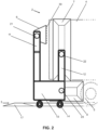
Figure 2 shows a schematic side view of the washing unit ofFigure 1 . -
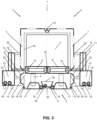
Figure 3 shows a schematic front view of a second embodiment of the washing unit, which is identical to the first embodiment ofFigure 1 , except that the vertical washing modules act on the upper area of the heavy-duty vehicle, in addition to acting on the side areas. -
Figure 4 shows a schematic side view of the washing unit ofFigure 3 . -
Figure 5 shows a schematic front view of a third embodiment of the washing unit, which is identical to the second embodiment ofFigure 3 , except that it does not have the transverse washing modules for acting selectively on the front, upper, and rear areas. -
Figure 6 shows a schematic side view of the washing unit ofFigure 5 . -
Figure 7 shows a schematic front view of a fourth embodiment of the washing unit having vertical washing modules adapted for acting on the side, front, upper, and rear areas and wheels of the heavy-duty vehicle, and fixed washing modules for acting on the lower area. -
Figure 8 shows a schematic side view of the washing unit ofFigure 7 . -
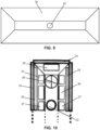
Figures 9 and 10 show a first example of one of the modules of the washing unit. -
Figures 11 and 12 show a second example of one of the modules of the washing unit with the possibility of being extended. -
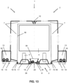
Figure 13 shows a schematic front view of a fifth embodiment of the washing unit. - The invention relates to a washing module for an
automated washing unit 1 of a heavy-duty vehicle having abody 4 with two side areas, an upper area, a lower area, a front area, and a rear area, andwheels 5. The heavy-duty vehicle can be a truck with a trailer, a trailer, a road train, a bus, or another similar road transport heavy-duty vehicle. -
Figures 1 and2 show a first embodiment of thewashing unit 1 comprising twomobile sub-units 2 which are coupled to one another forming a gantry-shaped tandem for being moved synchronously along the heavy-duty vehicle. Eachmobile sub-unit 2 has avertical washing module 7 for discharging cleaning agents on one of the side areas of thebody 4 of the heavy-duty vehicle, with thevertical washing modules 7 facing and separated from one another by a distance substantially similar to the width of thebody 4 of the heavy-duty vehicle. The twomobile sub-units 2 are moved parallel to the side areas of thebody 4 of the heavy-duty vehicle. - Each
mobile sub-unit 2 comprises amain body 13 having asupport arm 22 attached by its free end to one of thevertical washing modules 7, thewashing module 7 comprising acasing 30 with an opening oriented towards the heavy-duty vehicle, and being arranged inside thecasing 30 cleaning agent discharge means 26, 27 for discharging cleaning agents on the heavy-duty vehicle through the opening and extraction means 24, 28 for extracting the cleaning agents discharged on the heavy-duty vehicle. Thevertical washing modules 7 are thereby close to the side areas of the heavy-duty vehicle, and as themobile sub-units 2 move forward, the cleaning agent discharge means 26, 27 wash the side areas of the heavy-duty vehicle, whereas the extraction means 24, 28 gradually extract the cleaning agents used during washing. - The
vertical washing module 7 has an elongated (for example, rectangular) configuration with a vertical arrangement, wherein the largest dimension of themodule 7 coincides with the height of thebody 4 of the heavy-duty vehicle. Therefore, by means of the movement of the twomobile sub-units 2, from the back part to the front part of the heavy-duty vehicle, the entire side area of thebody 4 of the heavy-duty vehicle is washed. - Additionally, the
main body 13 of eachmobile sub-unit 2 has anothersupport arm 23 which is attached by its free end to ahorizontal washing module 8 which, like themodule 7, also comprises acasing 30 with an opening oriented towards the heavy-duty vehicle, and being arranged inside thecasing 30 cleaning agent discharge means 26, 27 for discharging cleaning agents on thewheels 5 of the heavy-duty vehicle through the opening and extraction means 24, 28 for extracting the cleaning agents discharged on the heavy-duty vehicle. - The
horizontal washing module 8 has an elongated (for example, rectangular) configuration with a horizontal arrangement, wherein the largest dimension of themodule 8 coincides with the width of one ormore wheels 5 of the heavy-duty vehicle. Therefore, by means of the movement of the twomobile sub-units 2, from the back part to the front part of the heavy-duty vehicle, all thewheels 5 of the heavy-duty vehicle are washed. Alternatively, the largest dimension of thevertical washing module 7 coincides with the height of thebody 4 plus the height of one of thewheels 5, such thatmodule 8 is not necessary for washing thewheels 5. - The
support arm 22 of thevertical washing module 7 is extendable for moving thewashing module 7 closer to or farther away from the side area of thebody 4 of the heavy-duty vehicle. Additionally, thesupport arm 23 of thehorizontal washing module 8 is also extendable for moving thewashing module 8 closer to or farther away from thewheel 5 of the heavy-duty vehicle. Both supportarms main body 13 perpendicular to the direction of movement of themobile sub-units 2. Thesupport arms modules body 4 of the heavy-duty vehicle adjusting to its width. Thesupport arms modules - The
support arm 22 of thevertical washing module 7 is attached by its end opposite the free end to avertical tower 12 of themain body 13. Thetower 12 is part of themain body 13, so thetower 12 can be an element integrally attached to thebody 13 or be an extension of thebody 13 itself. Themodule 7 is therefore in the vertical arrangement with respect to the side area of thebody 4, and by means of the movement of themobile sub-units 2, from the back part to the front part of the heavy-duty vehicle, the entire side area of thebody 4 of the heavy-duty vehicle is washed. - Alternatively, the
vertical tower 12 is extendable in the vertical direction with respect to themain body 13, such that thevertical washing module 7 is mobile in the vertical direction together with thetower 12. Additionally, thesupport arm 22 of thevertical washing module 7 is rotatable about its longitudinal axis for rotating thewashing module 7 over the side area of thebody 4 of the heavy-duty vehicle, with thearm 22 being rotatable by an angle of at least 90°. Themodule 7 is therefore vertically mobile and rotatable with respect to the side area, whereby thesupport arm 22 can be rotated to situate themodule 7 in the horizontal arrangement, and move thesupport arm 22 vertically, thereby modifying the direction in which the means 26, 27 act to perform cleaning with upward and downward vertical movements. The vertical movement of themodule 7 in the horizontal arrangement may be combined with the movement of themobile sub-units 2 for washing the entire side area. - Additionally, the
vertical washing module 7 is inclinable with respect to the side area of thebody 4. The inclination is obtained with an articulation (not depicted), the articulation is arranged between themodule 7 and thesupport arm 22, or is arranged between thesupport arm 22 and themain body 13. Themodule 7 can therefore be adapted to inclined surfaces, such as the cab of the heavy-duty vehicle for example. - The
washing unit 1 additionally comprises atread way 3 for arranging the heavy-duty vehicle and has fixedwashing modules 9, and like thevertical washing modules 7 andhorizontal washing modules 8, each of themodules 9 comprises acasing 30 with an opening oriented towards the heavy-duty vehicle, being arranged inside thecasing 30 cleaning agent discharge means 26, 27 for discharging cleaning agents on the lower area of thebody 4 of the heavy-duty vehicle through the opening and extraction means 24, 28 for extracting the cleaning agents discharged on the heavy-duty. - The
tread way 3 is impermeable, having a certain liquid tightness capacity, to prevent pouring onto the ground/into the environment. - The
tread way 3 comprises a cleaning agent andpower supply inlet 18, and anevacuation outlet 19 for evacuating the cleaning agents towards an area for the filtration, treatment, and recirculation of the cleaning agents towards theinlet 18. Theinlet 18 is connected with the cleaning agent discharge means 26, 27 and theoutlet 19 is connected with the extraction means 24, 28. Therefore, the cleaning agents that have been used in washing the heavy-duty vehicle can be used again after having been filtered and treated. - The fixed
washing modules 9 are arranged on acollector 20 channeling the cleaning agents discharged on the heavy-duty vehicle towards theoutlet 19. - The
tread way 3 comprises a set oftread plates 17 that can be coupled to one another to form tracks for arranging the heavy-duty vehicle. Thetread plates 17 forming the ends of the tracks have a slope for defining an inlet ramp and an outlet ramp in each track. - The
tread plates 17 are attached to each side of thecollector 20 to form an assembly of a width similar to the width of a heavy-duty vehicle, for example, the maximum regulatory width for the ordinary road transport is of 2.55 meters. The length of the set of thetread plates 17 and the collector is similar to the length of a heavy-duty vehicle, estimated to be about 20 meters. - The
tread plates 17 and thecollector 20 are coupled together in a leak-tight manner for ensuring impermeability. - The
tread plates 17 can be disassembled from one another and can also be disassembled with respect to thecentral collector 20 to facilitate stacking and transport. Furthermore, thecollector 20 is a flexible structure that can be folded to thus reduce the size of thetread way 3 and facilitate transport. - The
washing unit 1 additionally comprises pumpingdevices 29 which are arranged in the fixedwashing modules 9 and/or in thecollector 20. Thesedevices 29 circulate the cleaning agents towards theoutlet 19, preventing particles of said agents from settling at the bottom of themodule 9 or thecollector 20. - The
tread way 3 comprisesguide rails 16 acting withguides 15 of themain bodies 13 for guiding the twomobile sub-units 2. The guide rails 16 are attached to thetread plates 17. - The
main body 13 of eachmobile sub-unit 2 haswheels 14 to facilitate movement. Thewheels 14 are motor-powered, and the guide rails 16 are a channel through which theguide 15 in the form of a wheel moves. Alternatively, thewheels 14 of the main body are freely rotating (not motor-powered) wheels, and the guide rails 16 are drive chains driven by a motor and theguides 15 are toothed wheels meshing with the chains. - The
main body 13 of eachmobile sub-unit 2 has anextendable tower 11 that can be extended in the vertical direction and at least onetransverse washing module 6 which, like thevertical modules 7,horizontal modules 8, and fixedmodules 9, also comprises acasing 30 with an opening oriented towards the heavy-duty vehicle, being arranged inside thecasing 30 cleaning agent discharge means 26, 27 and extraction means 24, 28 of the cleaning agents discharged on the heavy-duty vehicle. Between theextendable towers 11 there is arranged asupport arm 21 in which thetransverse washing module 6 is rotatably assembled, such that thetransverse washing module 6 can be oriented for discharging cleaning agents on the front, upper, and rear areas of thebody 4 of the heavy-duty vehicle. - As shown in
Figure 1 , thewashing unit 1 preferably has twotransverse washing modules 6 which are attached to one another by coupling means 10, said means 10 serving to attach the twomobile sub-units 2 to one another and form the gantry-shaped tandem. Alternatively thesupport arm 21 can be extended between theextendable towers 11 attaching the twomobile sub-units 2. The joint movement of the twomobile sub-units 2 is additionally assured by the guiding coupling of themain bodies 13 with thetread way 3 through the guide rails 16 and theguides 15. - The
support arm 21 is rotatable by an angle of at least 180°, such that the joint action of the rotation of thearm 21, the movement in the vertical direction of theextendable towers 11, and the movement of themobile sub-units 2, allows thetransverse washing modules 6 to be oriented so as to act alternatively on the front, upper, and rear areas of thebody 4 of the heavy-duty vehicle. InFigure 1 thetransverse washing modules 6 are illustrated acting on the upper area of thebody 4, and inFigure 2 they are illustrated acting on the rear area of thebody 4. - Additionally, the
extendable tower 11 is laterally movable on themain carriage 13. Thetower 11 is movable with respect to thetower 12 in a direction parallel to the side areas of thebody 4 of the heavy-duty vehicle, and in the same direction of movement of themobile sub-units 2. This lateral movement of thetower 11 allows thetransverse washing modules 6 to be moved closer to or farther away from the front, or rear, surface of thebody 4, without having to move themobile sub-units 2. Moreover, when themodules 6 act on the upper area, slight movement of themodules 6 in the longitudinal direction of thebody 4 is also allowed. - The
extendable tower 11 and thetower 12 are arranged on themain carriage 13 in different planes, such that thetower 11 is laterally movable on themain carriage 13 without colliding with thetower 12. As can be observed inFigure 1 , thetower 11 is arranged in an outer plane with respect to thetower 12. - The
main body 13 of eachmobile sub-unit 2 has a cleaning agent andpower supply inlet 18 which is connected with the cleaning agent discharge means 26, 27 of thewashing module outlet 19 which is connected with the extraction means 24, 28 of thewashing module inlet 18 of themain body 13. - Alternatively or additionally, the
main body 13 of eachmobile sub-unit 2 has auxiliary cleaning agent supply and power supply means which are connected with the cleaning agent discharge means 26, 27 of thewashing module washing module main body 13. Themain body 13 can thereby work autonomously without having to be connected with a cleaning agent and power supply. - The coordinated action of the
vertical modules 7,horizontal modules 8,transverse modules 6, and fixedmodules 9 allows virtually the entire surface of the heavy-duty vehicle to be covered, such that complete washing of the vehicle is achieved with an efficient management of the cleaning agents. -
Figures 3 and4 show a second embodiment of the washing unit, which is identical to the first embodiment described in the preceding paragraphs, and differs only in thevertical washing modules 7, therefore the above description for the first example ofFigures 1 and2 is applicable to the second example ofFigures 3 and4 . - Unlike
Figures 1 and2 , thevertical washing module 7 ofFigures 3 and4 is L-shaped for discharging cleaning agents on the upper area and one of the side areas of thebody 4 of the heavy-duty vehicle, with thevertical washing modules 7 of themobile sub-units 2 being attached to one another to form the gantry-shaped tandem. In this case, washing the upper area of thebody 4 is performed with thetransverse modules 6 and the upper part of thevertical washing modules 7. - The upper part of the
vertical washing modules 7 of eachmobile sub-unit 2 are attached by coupling means 10, such that the attachment of the vertical washing modules forms another gantry complementing the rigidity of the gantry-shaped tandem which is obtained by the coupling means 10 attaching thetransverse washing modules 6. -
Figures 5 and6 show a third embodiment of the washing unit, which is identical to the second embodiment described in the preceding paragraphs, and differs only in that it does not have theextendable towers 11 between which thesupport arm 21 of thewashing modules transversal 6 is arranged, such that on the upper area of thebody 4 only the upper part of thevertical washing modules 7 acts. The entire above description for the first and second examples ofFigures 1 ,2 ,3 and4 is applicable to the third example ofFigures 5 and6 . -
Figures 7 and8 show a fourth embodiment of thewashing unit 1 which is identical to the examples described in the preceding paragraphs in reference to thetread way 3 with the fixed modules, and to themain bodies 13 of themobile sub-units 2. This fourth embodiment differs from the preceding embodiments in that there are nohorizontal washing modules 8 andtransverse washing modules 6, and instead there arevertical washing modules 7 acting on the side, upper, front, and rear areas, and wheels of the heavy-duty vehicle. Therefore, the entire above description for the examples ofFigures 1 ,2 ,3 ,4 ,5 , and6 is applicable to the fourth example ofFigures 7 and8 insofar as they are related. - The
automated washing unit 1 of the heavy-duty vehicle of this fourth embodiment comprises twomobile sub-units 2 which are coupled to one another forming the gantry-shaped tandem for being moved synchronously along the heavy-duty vehicle. Eachmobile sub-unit 2 comprises themain body 13 having thesupport arm 22 attached by its free end to one of thevertical washing modules 7, thewashing module 7 comprising thecasing 30 with the cleaning agent discharge means 26, 27 and the extraction means 24, 28. - The
vertical washing module 7 of eachmobile sub-unit 2 comprises a central part 7.1 and at least one end part 7.2, 7.3 which is articulated with respect to an end of the central part 7.1, and wherein the central part 7.1 is attached to themain body 13 of themobile sub-unit 2 by means of thesupport arm 22, and wherein each of the parts 7.1, 7.2, 7.3 ofmodule 7 comprises arespective casing 30, the cleaning agent discharge means 26, 27 and the extraction means 24, 28 being arranged inside thecasing 30. - As shown in
Figure 9 , thevertical washing module 7 comprises a central part 7.1, an upper end part 7.2, and a lower end part 7.3, wherein the central part 7.1 is articulated by its ends with the end parts 7.2, 7.3 by means of a respective articulation 7.4. The central part 7.1 is configured for discharging cleaning agents on one of the side areas of thebody 4, the upper end part 7.2 on the upper area, and the lower end part 7.3 on thewheels 5. - The articulations 7.4 are configured for rotating the end parts 7.2, 7.3 with respect to the central part 7.1, and are additionally configured for rotating the end parts 7.2, 7.3 about their longitudinal axis. The articulations 7.4 are configured for allowing the rotation of the parts 7.1, 7.2, 7.3 with respect to one another according to an angle of at least 180°, and are additionally configured for allowing the rotation of the end parts also by an angle of rotation of at least 180°.
-
Figure 8 depicts the upper end part 7.2 rotated 90° with respect to the central part 7.1, and the lower end part 7.3 aligned with the central part 7.1, such that the upper end part 7.2 is oriented towards the upper area of thebody 4, the central part 7.1 is oriented towards one of the side areas, and the lower end part is oriented towards thewheels 5. Therefore, with this arrangement of themodule 7, by moving themobile sub-units 2 the side and upper areas and wheels of the heavy-duty vehicle are covered, whereas themodules 9 act synchronously on the lower area. Additionally, by rotating the lower end part 7.3 90° with respect to the central part 7.1, the lower end part 7.3 can be arranged oriented towards the lower area of the heavy-duty vehicle. - In the same arrangement depicted in
Figure 8 , by means rotating thesupport arm 22 90°, the upper end part 7.2 can be arranged oriented towards the front or rear area of thebody 4, whereas the central part 7.1 and the lower end part 7.3 are oriented towards the side area of thebody 4, such that by extending thetower 12 in the vertical direction, the parts 7.1 ,7.2, 7.3 of themodule 7 can be moved for simultaneously washing the side areas and the front or rear area of thebody 4. - The lower end part 7.3 can be rotated with respect to the central part 7.1 by means of the articulation 7.4 for moving the part 7.3 closer to the heavy-duty vehicle and arranging it in a position in which it projects with respect to the part 7.1, such that said part 7.3 is used for improving the collection of the cleaning agents that have been discharged on the heavy-duty vehicle.
- By extending the
support arm 22, the distance between the central part 7.1 and the side area of thebody 4 of the heavy-duty vehicle can be adjusted, and therefore the distance of themodules 7 can be adjusted to the width of the heavy-duty vehicle to be washed. - The upper end part 7.2 has coupling means 10 arranged at its end opposite the end in which the articulation 7.4 for the attachment with the central part 7.1 is located. The coupling means 10 are used for establishing a removable coupling with the upper end part 7.2 of the other
mobile sub-unit 2, (which is not depicted inFigure 7 for the sake of clarity). -
Figures 9 and 10 show a first example of one of themodules Figure 10 , the opening of thecasing 30 of themodule suction device 24. Thedevice 24 is configured for establishing a pneumatic seal between thewashing module - Therefore, the
device 24 can operate as an air blowing device, an air suction device, or an air blowing and suction device. Theair blowing device 24 establishes the pneumatic seal by means of the injection of the air flow, whereas theair suction device 24 establishes the pneumatic seal by means of the suction of the air flow, and the air blowing andsuction device 24 establishes the pneumatic seal by means of the alternating injection and suction of the air flow. - The
device 24 performing the suction function can be used as the extraction means for extracting the cleaning agents that have been used in washing the heavy-duty vehicle. When thedevice 24 is not used performing the suction function, there is arranged inside thecasing 30 of the module aextractor 28 for extracting the cleaning agents; nonetheless, for better assuring the extraction of such agents, theextractor 28 and thedevice 24 performing the suction function can be used simultaneously. - The
device 24 for establishing the pneumatic seal is particularly useful in thevertical washing modules 7 andtransverse washing modules 6 acting on the front, upper, rear, and side areas of thebody 4 of the heavy-duty vehicle, which are smooth surface areas against which the pneumatic seal can be efficiently applied. - The cleaning agent discharge means 26, 27 comprise a
steam device 26 and/or aspraying device 27. Both are arranged inside thecasing 30 and act through the opening of thecasing 30. Thesteam device 26 discharges steam or steam mixed with a cleaning product. The sprayingdevice 27 discharges water or water mixed with a cleaning product, such as soap or other similar products. The sprayingdevice 27 comprises sprayers distributed inside thecasing 30 which can be fixed sprayers, circular sprayers, oscillating sprayers, or a combination thereof. - Additionally, a
scrubbing device 25 for increasing cleaning efficiency is arranged inside thecasing 30 of thewashing module device 25 can be rollers or brushes, which can be fixed or be operated by vibration or rotational movement. As shown inFigure 10 , thedevice 25 consists of two rectangular-shaped brushes extending parallel to the largest sides of the perimeter contour of theopening 30. - The opening of the
casing 30 configures and demarcates the work area of the module, determining the efficacy and efficiency of the washing tasks depending on the optimal adaptability and concentrated action of the cleaning agent discharge means integrated in thecasing 30. -
Figures 11 and 12 show a second example of one of themodules Figures 9 and 10 , except that thecasing 30 of thewashing modules washing module Figures 9 and 10 is applicable to this second example ofFigures 11 and 12 . - The washing modules of
Figures 9 to 12 can be applicable to any one of the washing units depicted in the examples ofFigures 1 to 8 . - The
casing 30 is manufactured in a physically, chemically, and thermally resistant material. -
Figure 13 shows a schematic front view of a fifth embodiment of thewashing unit 1 wherein thevertical washing modules 7 are attached directly to themain bodies 13 without using thesupport arms 22. Thewashing unit 1 comprises twomobile sub-units 2 which are coupled to one another forming a gantry-shaped tandem for being moved synchronously along the heavy-duty vehicle. Eachmobile sub-unit 2 comprises amain body 13 which is attached to awashing module 7, thewashing module 7 comprising acasing 30 with an opening oriented towards the heavy-duty vehicle, and being arranged inside thecasing 30 the cleaning agent discharge means 26, 27 for discharging cleaning agents on the heavy-duty vehicle through the opening and extraction means 24, 28 for extracting the cleaning agents discharged on the heavy-duty vehicle. The entire above description for the other examples of thewashing unit 1 is applicable to this fifth embodiment insofar as they are related.
Claims (11)
- Washing module for an automated washing unit of a heavy-duty vehicle, comprising a casing (30) with an opening oriented towards the heavy-duty vehicle, wherein inside the casing (30) there are arranged cleaning agent discharge means (26, 27) for discharging cleaning agents on the heavy-duty vehicle through the opening and wherein inside the casing (30) there are also arranged extraction means (24, 28) for extracting the cleaning agents discharged on the heavy-duty vehicle.
- Module according to claim 1, wherein the casing (30) of the washing module has along its perimeter contour an air blowing device (24) for establishing a pneumatic seal between the washing module and the heavy-duty vehicle.
- Module according to claim 1, wherein the extraction means (24) are an air suction device (24) which is arranged along the perimeter contour of the opening of the casing (30) for extracting the cleaning agents and for establishing a pneumatic seal between the washing module and the heavy-duty vehicle.
- Module according to claim 1, wherein the opening of the casing (30) of the washing module has along its perimeter contour an air blowing and suction device (24) for establishing a pneumatic seal between the washing module and the heavy-duty vehicle by means of the alternating injection and suction of an air flow.
- Module according to any of the preceding claims, wherein the cleaning agent discharge means (26, 27) comprise a steam device (26) and/or a spraying device (27).
- Module according to any of the preceding claims, wherein a scrubbing device (25) is arranged inside the casing (30) of the washing module.
- Module according to any of the preceding claims, wherein the casing (30) of the washing modules has at least two extendable parts that can be extended with respect to one another for increasing or decreasing the size of the opening of the washing module.
- Module according to any of the preceding claims, comprising a central part (7.1) and at least one end part (7.2, 7.3) which is articulated with respect to an end of the central part (7.1), and wherein each of the parts (7.1, 7.2, 7.3) of the module (7) comprises a respective casing (30), the cleaning agent discharge means (26, 27) and the extraction means (24, 28) being arranged inside the casing (30).
- Module according to the preceding claim, wherein the washing module comprises a central part (7.1), an upper end part (7.2), and a lower end part (7.3), wherein the central part (7.1) is articulated by its ends with the end parts (7.2, 7.3) by means of a respective articulation (7.4).
- Module according to the preceding claim, wherein the articulations (7.4) are configured for rotating the end parts (7.2, 7.3) with respect to the central part (7.1).
- Module according to claim 9 or 10, wherein the articulations (7.4) are configured for rotating the end parts (7.2, 7.3) about their longitudinal axis.
Applications Claiming Priority (3)
| Application Number | Priority Date | Filing Date | Title |
|---|---|---|---|
| ES201900042 | 2019-03-20 | ||
| EP20725208.1A EP3943349B1 (en) | 2019-03-20 | 2020-03-18 | Automated washing unit for a heavy-duty vehicle |
| PCT/ES2020/070190 WO2020188135A1 (en) | 2019-03-20 | 2020-03-18 | Automated washing unit for a heavy goods vehicle |
Related Parent Applications (2)
| Application Number | Title | Priority Date | Filing Date |
|---|---|---|---|
| EP20725208.1A Division EP3943349B1 (en) | 2019-03-20 | 2020-03-18 | Automated washing unit for a heavy-duty vehicle |
| EP20725208.1A Division-Into EP3943349B1 (en) | 2019-03-20 | 2020-03-18 | Automated washing unit for a heavy-duty vehicle |
Publications (4)
| Publication Number | Publication Date |
|---|---|
| EP4253169A2 true EP4253169A2 (en) | 2023-10-04 |
| EP4253169A3 EP4253169A3 (en) | 2023-12-13 |
| EP4253169B1 EP4253169B1 (en) | 2025-05-07 |
| EP4253169C0 EP4253169C0 (en) | 2025-05-07 |
Family
ID=70680525
Family Applications (2)
| Application Number | Title | Priority Date | Filing Date |
|---|---|---|---|
| EP20725208.1A Active EP3943349B1 (en) | 2019-03-20 | 2020-03-18 | Automated washing unit for a heavy-duty vehicle |
| EP23186044.6A Active EP4253169B1 (en) | 2019-03-20 | 2020-03-18 | Automated washing unit for a heavy-duty vehicle |
Family Applications Before (1)
| Application Number | Title | Priority Date | Filing Date |
|---|---|---|---|
| EP20725208.1A Active EP3943349B1 (en) | 2019-03-20 | 2020-03-18 | Automated washing unit for a heavy-duty vehicle |
Country Status (3)
| Country | Link |
|---|---|
| EP (2) | EP3943349B1 (en) |
| ES (2) | ES3032313T3 (en) |
| WO (1) | WO2020188135A1 (en) |
Citations (1)
| Publication number | Priority date | Publication date | Assignee | Title |
|---|---|---|---|---|
| EP2712776A1 (en) | 2012-09-27 | 2014-04-02 | Michaud-Grosbenoit, Frédéric | Truck-washing station and truck-washing method using such a station |
Family Cites Families (2)
| Publication number | Priority date | Publication date | Assignee | Title |
|---|---|---|---|---|
| ES2333926B1 (en) * | 2007-06-28 | 2011-01-26 | Istobal, S.A | SYSTEM FOR PRESSURE WASHING OF VEHICLES. |
| ES2368290B1 (en) * | 2010-04-27 | 2012-09-21 | Proyectos Y Realizaciones San Cristobal S.L | INSTALLATION FOR WASHING OF GROUND VEHICLES |
-
2020
- 2020-03-18 WO PCT/ES2020/070190 patent/WO2020188135A1/en not_active Ceased
- 2020-03-18 ES ES23186044T patent/ES3032313T3/en active Active
- 2020-03-18 EP EP20725208.1A patent/EP3943349B1/en active Active
- 2020-03-18 ES ES20725208T patent/ES2964491T3/en active Active
- 2020-03-18 EP EP23186044.6A patent/EP4253169B1/en active Active
Patent Citations (1)
| Publication number | Priority date | Publication date | Assignee | Title |
|---|---|---|---|---|
| EP2712776A1 (en) | 2012-09-27 | 2014-04-02 | Michaud-Grosbenoit, Frédéric | Truck-washing station and truck-washing method using such a station |
Also Published As
| Publication number | Publication date |
|---|---|
| EP4253169A3 (en) | 2023-12-13 |
| EP3943349A1 (en) | 2022-01-26 |
| EP4253169B1 (en) | 2025-05-07 |
| EP3943349B1 (en) | 2023-09-13 |
| ES3032313T3 (en) | 2025-07-17 |
| ES2964491T3 (en) | 2024-04-08 |
| WO2020188135A1 (en) | 2020-09-24 |
| EP3943349C0 (en) | 2023-09-13 |
| EP4253169C0 (en) | 2025-05-07 |
Similar Documents
| Publication | Publication Date | Title |
|---|---|---|
| CN209798631U (en) | Road pollution cleaning vehicle | |
| CN205966582U (en) | Clear car machine of open car | |
| CN110143185B (en) | Gantry type full-automatic car washing system | |
| CN211395546U (en) | Dirt-absorbing trolley device for railway ballast bed dirt-absorbing vehicle | |
| CN206462946U (en) | It is a kind of to integrate the floor cleaning trolley mopped floor with cleaning function | |
| KR101831941B1 (en) | Particulate Matter collector for railway vehicles | |
| CN212503003U (en) | Bulk cargo cleaning device | |
| EP3943349B1 (en) | Automated washing unit for a heavy-duty vehicle | |
| CN111994666B (en) | Bulk material cleaning device | |
| RU2755281C1 (en) | Self-propelled garbage collection machine | |
| CN208528352U (en) | Welding platform is used in a kind of machining | |
| KR100627027B1 (en) | Vacuum suction sprinkler | |
| EP2920371B1 (en) | Device for cleaning surfaces | |
| CN206680933U (en) | A kind of air stream drives for road sweeper pick up dirt device | |
| CN208441031U (en) | A kind of road sweeper | |
| CN111485519A (en) | Municipal road engineering desilting device | |
| KR102308523B1 (en) | Removing Dust Device of Road | |
| CN107829356B (en) | Slag water recovery type high-pressure water cleaning marking automobile | |
| CN219324530U (en) | Cleaning device for railway locomotive wheels | |
| CA3012208C (en) | Mat washing system | |
| CN214028558U (en) | A self-inspection and cleaning device for mining vehicles | |
| CN213681932U (en) | Bridge cleaning device | |
| CN215922145U (en) | Engineering vehicle wheel washing machine convenient to move | |
| CN107321671A (en) | High-pressure water rust-removing vehicle and derusting method | |
| US12269069B2 (en) | Mat washing system |
Legal Events
| Date | Code | Title | Description |
|---|---|---|---|
| PUAI | Public reference made under article 153(3) epc to a published international application that has entered the european phase |
Free format text: ORIGINAL CODE: 0009012 |
|
| STAA | Information on the status of an ep patent application or granted ep patent |
Free format text: STATUS: THE APPLICATION HAS BEEN PUBLISHED |
|
| AC | Divisional application: reference to earlier application |
Ref document number: 3943349 Country of ref document: EP Kind code of ref document: P |
|
| AK | Designated contracting states |
Kind code of ref document: A2 Designated state(s): AL AT BE BG CH CY CZ DE DK EE ES FI FR GB GR HR HU IE IS IT LI LT LU LV MC MK MT NL NO PL PT RO RS SE SI SK SM TR |
|
| REG | Reference to a national code |
Ref country code: DE Ref legal event code: R079 Free format text: PREVIOUS MAIN CLASS: B60S0003000000 Ipc: B60S0003040000 Ref country code: DE Ref legal event code: R079 Ref document number: 602020051138 Country of ref document: DE Free format text: PREVIOUS MAIN CLASS: B60S0003000000 Ipc: B60S0003040000 |
|
| PUAL | Search report despatched |
Free format text: ORIGINAL CODE: 0009013 |
|
| AK | Designated contracting states |
Kind code of ref document: A3 Designated state(s): AL AT BE BG CH CY CZ DE DK EE ES FI FR GB GR HR HU IE IS IT LI LT LU LV MC MK MT NL NO PL PT RO RS SE SI SK SM TR |
|
| RIC1 | Information provided on ipc code assigned before grant |
Ipc: B60S 3/00 20060101ALI20231109BHEP Ipc: B60S 3/04 20060101AFI20231109BHEP |
|
| STAA | Information on the status of an ep patent application or granted ep patent |
Free format text: STATUS: REQUEST FOR EXAMINATION WAS MADE |
|
| 17P | Request for examination filed |
Effective date: 20240611 |
|
| RBV | Designated contracting states (corrected) |
Designated state(s): AL AT BE BG CH CY CZ DE DK EE ES FI FR GB GR HR HU IE IS IT LI LT LU LV MC MK MT NL NO PL PT RO RS SE SI SK SM TR |
|
| GRAP | Despatch of communication of intention to grant a patent |
Free format text: ORIGINAL CODE: EPIDOSNIGR1 |
|
| STAA | Information on the status of an ep patent application or granted ep patent |
Free format text: STATUS: GRANT OF PATENT IS INTENDED |
|
| INTG | Intention to grant announced |
Effective date: 20241025 |
|
| GRAS | Grant fee paid |
Free format text: ORIGINAL CODE: EPIDOSNIGR3 |
|
| GRAA | (expected) grant |
Free format text: ORIGINAL CODE: 0009210 |
|
| STAA | Information on the status of an ep patent application or granted ep patent |
Free format text: STATUS: THE PATENT HAS BEEN GRANTED |
|
| AC | Divisional application: reference to earlier application |
Ref document number: 3943349 Country of ref document: EP Kind code of ref document: P |
|
| AK | Designated contracting states |
Kind code of ref document: B1 Designated state(s): AL AT BE BG CH CY CZ DE DK EE ES FI FR GB GR HR HU IE IS IT LI LT LU LV MC MK MT NL NO PL PT RO RS SE SI SK SM TR |
|
| REG | Reference to a national code |
Ref country code: GB Ref legal event code: FG4D |
|
| REG | Reference to a national code |
Ref country code: CH Ref legal event code: EP |
|
| REG | Reference to a national code |
Ref country code: DE Ref legal event code: R096 Ref document number: 602020051138 Country of ref document: DE |
|
| REG | Reference to a national code |
Ref country code: IE Ref legal event code: FG4D |
|
| U01 | Request for unitary effect filed |
Effective date: 20250526 |
|
| U07 | Unitary effect registered |
Designated state(s): AT BE BG DE DK EE FI FR IT LT LU LV MT NL PT RO SE SI Effective date: 20250603 |
|
| REG | Reference to a national code |
Ref country code: ES Ref legal event code: FG2A Ref document number: 3032313 Country of ref document: ES Kind code of ref document: T3 Effective date: 20250717 |
|
| U1N | Appointed representative for the unitary patent procedure changed after the registration of the unitary effect |
Representative=s name: GALBAIAN S.COOP.; ES |
|
| PG25 | Lapsed in a contracting state [announced via postgrant information from national office to epo] |
Ref country code: GR Free format text: LAPSE BECAUSE OF FAILURE TO SUBMIT A TRANSLATION OF THE DESCRIPTION OR TO PAY THE FEE WITHIN THE PRESCRIBED TIME-LIMIT Effective date: 20250808 Ref country code: NO Free format text: LAPSE BECAUSE OF FAILURE TO SUBMIT A TRANSLATION OF THE DESCRIPTION OR TO PAY THE FEE WITHIN THE PRESCRIBED TIME-LIMIT Effective date: 20250807 |
|
| PG25 | Lapsed in a contracting state [announced via postgrant information from national office to epo] |
Ref country code: PL Free format text: LAPSE BECAUSE OF FAILURE TO SUBMIT A TRANSLATION OF THE DESCRIPTION OR TO PAY THE FEE WITHIN THE PRESCRIBED TIME-LIMIT Effective date: 20250507 |
|
| PG25 | Lapsed in a contracting state [announced via postgrant information from national office to epo] |
Ref country code: HR Free format text: LAPSE BECAUSE OF FAILURE TO SUBMIT A TRANSLATION OF THE DESCRIPTION OR TO PAY THE FEE WITHIN THE PRESCRIBED TIME-LIMIT Effective date: 20250507 |
|
| PG25 | Lapsed in a contracting state [announced via postgrant information from national office to epo] |
Ref country code: RS Free format text: LAPSE BECAUSE OF FAILURE TO SUBMIT A TRANSLATION OF THE DESCRIPTION OR TO PAY THE FEE WITHIN THE PRESCRIBED TIME-LIMIT Effective date: 20250807 |
|
| PG25 | Lapsed in a contracting state [announced via postgrant information from national office to epo] |
Ref country code: IS Free format text: LAPSE BECAUSE OF FAILURE TO SUBMIT A TRANSLATION OF THE DESCRIPTION OR TO PAY THE FEE WITHIN THE PRESCRIBED TIME-LIMIT Effective date: 20250907 |
|
| PG25 | Lapsed in a contracting state [announced via postgrant information from national office to epo] |
Ref country code: SM Free format text: LAPSE BECAUSE OF FAILURE TO SUBMIT A TRANSLATION OF THE DESCRIPTION OR TO PAY THE FEE WITHIN THE PRESCRIBED TIME-LIMIT Effective date: 20250507 |
|
| PG25 | Lapsed in a contracting state [announced via postgrant information from national office to epo] |
Ref country code: CZ Free format text: LAPSE BECAUSE OF FAILURE TO SUBMIT A TRANSLATION OF THE DESCRIPTION OR TO PAY THE FEE WITHIN THE PRESCRIBED TIME-LIMIT Effective date: 20250507 |
|
| PG25 | Lapsed in a contracting state [announced via postgrant information from national office to epo] |
Ref country code: SK Free format text: LAPSE BECAUSE OF FAILURE TO SUBMIT A TRANSLATION OF THE DESCRIPTION OR TO PAY THE FEE WITHIN THE PRESCRIBED TIME-LIMIT Effective date: 20250507 |
|
| PLBE | No opposition filed within time limit |
Free format text: ORIGINAL CODE: 0009261 |
|
| STAA | Information on the status of an ep patent application or granted ep patent |
Free format text: STATUS: NO OPPOSITION FILED WITHIN TIME LIMIT |
|
| REG | Reference to a national code |
Ref country code: CH Ref legal event code: L10 Free format text: ST27 STATUS EVENT CODE: U-0-0-L10-L00 (AS PROVIDED BY THE NATIONAL OFFICE) Effective date: 20260318 |
|
| 26N | No opposition filed |
Effective date: 20260210 |