EP4253154A1 - Camera system for vehicle - Google Patents
Camera system for vehicle Download PDFInfo
- Publication number
- EP4253154A1 EP4253154A1 EP22165328.0A EP22165328A EP4253154A1 EP 4253154 A1 EP4253154 A1 EP 4253154A1 EP 22165328 A EP22165328 A EP 22165328A EP 4253154 A1 EP4253154 A1 EP 4253154A1
- Authority
- EP
- European Patent Office
- Prior art keywords
- vehicle
- camera module
- illumination system
- camera
- housing unit
- Prior art date
- Legal status (The legal status is an assumption and is not a legal conclusion. Google has not performed a legal analysis and makes no representation as to the accuracy of the status listed.)
- Granted
Links
Images




Classifications
-
- B—PERFORMING OPERATIONS; TRANSPORTING
- B60—VEHICLES IN GENERAL
- B60R—VEHICLES, VEHICLE FITTINGS, OR VEHICLE PARTS, NOT OTHERWISE PROVIDED FOR
- B60R13/00—Elements for body-finishing, identifying, or decorating; Arrangements or adaptations for advertising purposes
- B60R13/005—Manufacturers' emblems, name plates, bonnet ornaments, mascots or the like; Mounting means therefor
-
- H—ELECTRICITY
- H04—ELECTRIC COMMUNICATION TECHNIQUE
- H04N—PICTORIAL COMMUNICATION, e.g. TELEVISION
- H04N7/00—Television systems
- H04N7/18—Closed-circuit television [CCTV] systems, i.e. systems in which the video signal is not broadcast
- H04N7/181—Closed-circuit television [CCTV] systems, i.e. systems in which the video signal is not broadcast for receiving images from a plurality of remote sources
-
- H—ELECTRICITY
- H04—ELECTRIC COMMUNICATION TECHNIQUE
- H04N—PICTORIAL COMMUNICATION, e.g. TELEVISION
- H04N23/00—Cameras or camera modules comprising electronic image sensors; Control thereof
- H04N23/57—Mechanical or electrical details of cameras or camera modules specially adapted for being embedded in other devices
Definitions
- the present invention relates to opto-electronic apparatus related to external parts of motor Vehicles. More particularly, the present invention relates to Vehicle logo illumination and camera system for motor Vehicles.
- the motor Vehicles have a logo embedded, embossed or illuminated around the external part of the Vehicle.
- the logo is affixed to show the manufacture details of the car. More often, the logo of the manufacturer is required for various purpose including homologation requirement to identify the Vehicle and legal requirement associated with the Vehicle.
- the logo of the Vehicle manufacturer is embedded, embossed or illuminated such that the logo is visible to the outside world to satisfy various requirement including the homologation.
- the modern Vehicles are equipped with a camera system to see front, rear and/or around the Vehicle. Therefore, to equip such camera system, the more sensible location to integrate such cameras often overlaps with the space or location of the logo portion, be it the front or the rear end of the Vehicle.
- the logo of the Vehicle is integrated into the bumpers i.e. either the front bumper or the rear bumper.
- the camera system is also integrated into the bumpers of the Vehicle which raises the problem of effective management of the space and location to mount each.
- the camera system or the illuminated logo system requires individual casing or housing space to work independently which also raises the problem of space management since the location and space of both the camera system and the logo system overlap with each other.
- a camera system for a vehicle the camera system for a vehicle a camera module configured to capture a field-of-view (FOV) of the camera module in a scenery at least around the vehicle, an illumination system configured to project at least one of a static image and a dynamic image, a housing unit configured to accommodate the camera module and the illumination system, wherein the housing unit is configured with an orifice, and a Switchable foil is configured to cover the orifice, wherein the Switchable foil is configured to be switched between an opaque state and a transparent state, a control unit configured to electronically switch the Switchable foil into the opaque state in an event the camera module is disabled and the illumination system is enabled to project at least one of the static image and the dynamic image, and electronically switch the Switchable foil into the transparent in state in an event the illumination system is disabled and the camera module is enabled to capture the field-of-view in a scenery at least around the Vehicle.
- FOV field-of-view
- the camera module is mounted within the housing unit such that the camera module is capable of capturing the field-of-view of the camera module in a scenery at least around the Vehicle through the orifice of the housing unit.
- the illumination system is mounted within the housing unit such that the illumination system is configured to project at least one of the static image and the dynamic image towards the orifice of the housing unit.
- the camera module captures the field-of-view in a scenery at least around the Vehicle and the Switchable foil turns transparent in an event the illumination system is disabled and the camera module is enabled to capture the field-of-view in a scenery at least around the Vehicle.
- the camera module and the illumination system are disposed within the housing unit such that the line-of-sights (LoSs) of the camera module and the illumination system are not in interference with each other.
- LoSs line-of-sights
- the housing unit is closed at all sides except from the orifice through which any light is allowed to enter or exit.
- the housing is made of one of plastic, metal and alloy.
- the switchable foil captures the light and displays the static image or the dynamic image on it, in an event the control unit switches the switchable foil to the opaque state.
- control unit further is configured to one of enable and disable one of the camera module and the illumination system.
- Various embodiments of the invention describe a method of operating a camera system for a vehicle, comprising: capturing a field-of-view by a camera module in a scenery at least around the vehicle, projecting at least one of a static image and a dynamic image by an illumination system, wherein a housing unit is configured to accommodate the camera module and the illumination system, the housing unit is configured with an orifice, and a switchable foil is configured to cover the orifice, the switchable foil is configured to be switched between an opaque state and a transparent state, electronically switching the switchable foil, by a control unit, into the opaque state in an event the camera module is disabled and the illumination system is enabled to project at least one of the static image and the dynamic image, and electronically switching the switchable foil, by the control unit, into the transparent state in an event the illumination system is disabled and the camera module is enabled to capture the field-of-view in a scenery at least around the vehicle.
- a camera system 200 integrated into one or more bumper 110 of a Vehicle 100.
- the camera system 200 is an integrated solution to provide better space utilization and operational capacity to a camera module 210 and an illumination system 220 of the Vehicle 100.
- the Vehicle 100 comprises a camera system 200 mounted into the bumper 110 of the Vehicle 100.
- the vehicle bumpers 110 are usually used to display the logo of the manufacturer of the Vehicle 100. Further, the bumpers 110 are strategically used to capture rear, front and/or 360-degree view around the Vehicle 100.
- the camera system 200 essentially comprises a camera module 210, an illumination system 220, a housing unit 230, a Switchable foil 240 and a control unit (not shown in Figures).
- the camera module 210 is configured to capture a field-of-view (FOV) of the camera module 210 in a scenery at least around the Vehicle 100.
- the camera may be a high-resolution camera configured to take night and day images as may be required for viewing rear end, front end or 360-degree view of the Vehicle 100.
- the illumination system 220 is configured to project at least one of a static image and a dynamic image.
- the illumination system 220 comprises one or more logo lamps configured to project static or dynamic images to a screen.
- the static or dynamic image may include but is not limited to a manufacturer logo, an advertisement image or an advertisement video.
- the housing unit 230 is configured to accommodate the camera module 210 and the illumination system 220, wherein the housing unit 230 is configured with an orifice 260.
- the housing unit 230 may be a single part or a multi part moulded or casted hosing configured to accommodate one or more components of the camera system 200.
- the materials used to manufacture the housing unit 230 may include but are not limited to polymer, metal, alloy or any combination thereof.
- the Switchable foil 240 is configured to cover the orifice 260, wherein the Switchable foil 240 is configured to be switched between an opaque state and a transparent state.
- the Switchable foil 240 may also be known as a smart glass or a switchable glass.
- the Switchable foil 240 is preferably made by sandwiching a smart film or a switchable film in-between a couple of glasses. The light transmission properties of the Switchable foil 240 are altered when voltage, light, or heat is applied.
- the Switchable foil 240 changes from a transparent to a translucent state and vice versa, changing from letting light pass through to blocking some or all wavelengths of light and vice versa.
- the two states of the Switchable foil 240 are an opaque state and a transparent state. In the opaque state, all the light rays are blocked and in the transparent state all the light rays or most of them are allowed to pass through.
- the Switchable foil 240 is changed or is switched from the opaque state to the transparent state and vice-versa by applying a voltage. The voltage is applied in a controlled manner and as and when required by the control unit.
- the control unit is configured to electronically switch the Switchable foil 240 from the transparent state to the opaque state in an event the camera module 210 is disabled and the illumination system 220 is enabled to project at least one of the static image and the dynamic image. Further, the control unit is configured to electronically switch the Switchable foil 240 from the opaque state into the transparent state in an event the illumination system 220 is disabled and the camera module 210 is enabled to capture the field-of-view in a scenery at least around the Vehicle 100.
- the control unit or the electronic control unit also known as an electronic control module (ECM)
- ECU electronice control module
- ECM electronice control module
- the development of a control unit involves both hardware and software required to perform the functions expected from a particular module and it is the camera module 210 and the Switchable foil 240 in the current example of the disclosure.
- the hardware may include but is not limited to a general purpose or a special purpose microcontroller or microprocessor.
- the camera module 210 is mounted within the housing unit 230 such that the camera module 210 is capable of capturing the field-of-view of the camera module 210 in a scenery at least around the Vehicle 100 though the orifice of the housing unit 230.
- the illumination system 220 is mounted within the housing unit 230 such that the illumination system 220 is configured to project at least one of the static image and the dynamic image towards the orifice 260 of the housing unit 230.
- the Switchable foil 240 turns transparent, in a controlled manner by the control unit, in an event the illumination system 220 is disabled and the camera module 210 is enabled to capture the field-of-view in a scenery at least around the Vehicle 100.
- the camera module 210 and the illumination system 220 are disposed within the housing unit 230 such that the line-of-sights (LoSs) of the camera module 210 and the illumination system 220 are not in interference with each other. Further, the housing unit 230 is closed at all sides except from the orifice 260 through which any light is allowed to enter or exit.
- LiSs line-of-sights
- the Switchable foil 240 captures the light and displays the static image or the dynamic image on it, in an event the control unit switches the Switchable foil 240 to the opaque state.
- the control unit further is configured to one of enable and disable one of the camera module 210 and the illumination system 220.
- the method 300 initiates at step 310.
- a field-of-view is captured by the camera module 210 in a scenery at least around the Vehicle 100.
- the housing unit 230 is configured to accommodate the camera module 210 and the illumination system 220, the housing unit 230 is configured with an orifice 260. Further, the Switchable foil 240 is configured to cover the orifice 260, and the Switchable foil 240 is configured to be switched between an opaque state and a transparent state.
- the Switchable foil 240 is electronically switched by the control unit into the opaque state in an event the camera module 210 is disabled and the illumination system 220 is enabled to project at least one of the static image and the dynamic image.
- the Switchable foil 240 is electronically switched by the control unit 250 into the transparent state in an event the illumination system 220 is disabled and the camera module 210 is enabled to capture the field-of-view in a scenery at least around the Vehicle 100.
- the method 300 terminates at step 360.
- the present disclosure advantageously encompasses a camera system 200 for effectively switching between the camera module 210 and the illumination system 220. Further, the camera module 210 and the illumination system 220 are effectively switched based on the requirement by the control unit such that independent functionality is not disturbed or compromised. The present disclosure allows mounting of the camera module 210 and the illumination system 220 within a same housing without affecting individual functionality.
Landscapes
- Engineering & Computer Science (AREA)
- Multimedia (AREA)
- Signal Processing (AREA)
- Mechanical Engineering (AREA)
- Studio Devices (AREA)
Abstract
Description
- The present invention relates to opto-electronic apparatus related to external parts of motor Vehicles. More particularly, the present invention relates to Vehicle logo illumination and camera system for motor Vehicles.
- The statements in this section merely provide background information related to the present disclosure and may not constitute prior art.
- Generally, the motor Vehicles have a logo embedded, embossed or illuminated around the external part of the Vehicle. The logo is affixed to show the manufacture details of the car. More often, the logo of the manufacturer is required for various purpose including homologation requirement to identify the Vehicle and legal requirement associated with the Vehicle. The logo of the Vehicle manufacturer is embedded, embossed or illuminated such that the logo is visible to the outside world to satisfy various requirement including the homologation.
- Further, the modern Vehicles are equipped with a camera system to see front, rear and/or around the Vehicle. Therefore, to equip such camera system, the more sensible location to integrate such cameras often overlaps with the space or location of the logo portion, be it the front or the rear end of the Vehicle. Particularly, the logo of the Vehicle is integrated into the bumpers i.e. either the front bumper or the rear bumper. The camera system is also integrated into the bumpers of the Vehicle which raises the problem of effective management of the space and location to mount each.
- More particularly, the camera system or the illuminated logo system requires individual casing or housing space to work independently which also raises the problem of space management since the location and space of both the camera system and the logo system overlap with each other.
- In view of the aforementioned drawbacks inherent in the existing state of the art, it is desirous to have an effective solution to mount both the camera system and the logo system.
- Various embodiments of the invention describe a camera system for a vehicle, the camera system for a vehicle a camera module configured to capture a field-of-view (FOV) of the camera module in a scenery at least around the vehicle, an illumination system configured to project at least one of a static image and a dynamic image, a housing unit configured to accommodate the camera module and the illumination system, wherein the housing unit is configured with an orifice, and a Switchable foil is configured to cover the orifice, wherein the Switchable foil is configured to be switched between an opaque state and a transparent state, a control unit configured to electronically switch the Switchable foil into the opaque state in an event the camera module is disabled and the illumination system is enabled to project at least one of the static image and the dynamic image, and electronically switch the Switchable foil into the transparent in state in an event the illumination system is disabled and the camera module is enabled to capture the field-of-view in a scenery at least around the Vehicle.
- In an embodiment, the camera module is mounted within the housing unit such that the camera module is capable of capturing the field-of-view of the camera module in a scenery at least around the Vehicle through the orifice of the housing unit.
- In a further embodiment, the illumination system is mounted within the housing unit such that the illumination system is configured to project at least one of the static image and the dynamic image towards the orifice of the housing unit.
- In a further embodiment, the camera module captures the field-of-view in a scenery at least around the Vehicle and the Switchable foil turns transparent in an event the illumination system is disabled and the camera module is enabled to capture the field-of-view in a scenery at least around the Vehicle.
- In a further embodiment, the camera module and the illumination system are disposed within the housing unit such that the line-of-sights (LoSs) of the camera module and the illumination system are not in interference with each other.
- In a further embodiment, the housing unit is closed at all sides except from the orifice through which any light is allowed to enter or exit.
- In a further embodiment, the housing is made of one of plastic, metal and alloy.
- In a further embodiment, the switchable foil captures the light and displays the static image or the dynamic image on it, in an event the control unit switches the switchable foil to the opaque state.
- In a further embodiment, the control unit further is configured to one of enable and disable one of the camera module and the illumination system.
- Various embodiments of the invention describe a method of operating a camera system for a vehicle, comprising: capturing a field-of-view by a camera module in a scenery at least around the vehicle, projecting at least one of a static image and a dynamic image by an illumination system, wherein a housing unit is configured to accommodate the camera module and the illumination system, the housing unit is configured with an orifice, and a switchable foil is configured to cover the orifice, the switchable foil is configured to be switched between an opaque state and a transparent state, electronically switching the switchable foil, by a control unit, into the opaque state in an event the camera module is disabled and the illumination system is enabled to project at least one of the static image and the dynamic image, and electronically switching the switchable foil, by the control unit, into the transparent state in an event the illumination system is disabled and the camera module is enabled to capture the field-of-view in a scenery at least around the vehicle.
- This summary is provided to introduce a selection of concepts in a simplified form that are further described below in the detailed description. This summary is not intended to identify key features or essential features of the claimed subject matter, nor is it intended to be used as an aid in determining the scope of the claimed subject matter.
- Other aspects, advantages, and salient features of the invention will become apparent to those skilled in the art from the following detailed description, which taken in conjunction with the annexed drawings, discloses exemplary embodiments of the invention.
- The invention itself, together with further features and attended advantages, will become apparent from consideration of the following detailed description, taken in conjunction with the accompanying drawings. One or more embodiments of the present invention are now described, by way of example only wherein like reference numerals represent like elements and in which:
-
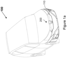
Figure 1a andFigure 1b illustrate each a Vehicle and its bumper configured with a camera system, in accordance with an exemplary embodiment of the present invention; -
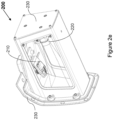
Figures 2a-2f illustrate each a different perspective view of the camera system, in accordance with an exemplary embodiment of the present invention; and -
Figure 3 illustrates a method flow chart for operating the camera system, in accordance with an exemplary embodiment of the present invention. - The drawings referred to in this description are not to be understood as being drawn to scale except if specifically noted, and such drawings are only exemplary in nature.
- The term "comprises", "comprising", "including", "having", "consist of' or any other variations indicate non-exclusive inclusion in order to cover a setup, structure or method that comprises a list of components or steps does not include only those components or steps but may include other components or steps not expressly listed or inherent to such setup or structure or method. Meaning thereby, one or more elements in an apparatus proceeded by "comprises... a" does not, without more constraints, preclude the existence of other elements or additional elements in the system or apparatus.
- For increasing the intelligibility of this invention, references are made to the embodiment illustrated in the accompanying Figures and description herein below, further, in the following Figures, the same reference numerals are used to identify the same components in alternative views.
- As illustrated in
Figures 1a and1b , described herein is acamera system 200 integrated into one ormore bumper 110 of aVehicle 100. Thecamera system 200 is an integrated solution to provide better space utilization and operational capacity to acamera module 210 and anillumination system 220 of theVehicle 100. - The
Vehicle 100 comprises acamera system 200 mounted into thebumper 110 of theVehicle 100. Thevehicle bumpers 110 are usually used to display the logo of the manufacturer of theVehicle 100. Further, thebumpers 110 are strategically used to capture rear, front and/or 360-degree view around theVehicle 100. - As illustrated in
Figures 2a-2f , described herein are the structural units of thecamera system 200. Thecamera system 200 essentially comprises acamera module 210, anillumination system 220, ahousing unit 230, aSwitchable foil 240 and a control unit (not shown in Figures). - The
camera module 210, as used hereinabove, is configured to capture a field-of-view (FOV) of thecamera module 210 in a scenery at least around theVehicle 100. The camera may be a high-resolution camera configured to take night and day images as may be required for viewing rear end, front end or 360-degree view of theVehicle 100. - The
illumination system 220, as used hereinabove, is configured to project at least one of a static image and a dynamic image. Theillumination system 220 comprises one or more logo lamps configured to project static or dynamic images to a screen. The static or dynamic image may include but is not limited to a manufacturer logo, an advertisement image or an advertisement video. - The
housing unit 230, as used hereinabove, is configured to accommodate thecamera module 210 and theillumination system 220, wherein thehousing unit 230 is configured with anorifice 260. Thehousing unit 230 may be a single part or a multi part moulded or casted hosing configured to accommodate one or more components of thecamera system 200. The materials used to manufacture thehousing unit 230 may include but are not limited to polymer, metal, alloy or any combination thereof. - The
Switchable foil 240, as used hereinabove, is configured to cover theorifice 260, wherein theSwitchable foil 240 is configured to be switched between an opaque state and a transparent state. TheSwitchable foil 240 may also be known as a smart glass or a switchable glass. TheSwitchable foil 240 is preferably made by sandwiching a smart film or a switchable film in-between a couple of glasses. The light transmission properties of theSwitchable foil 240 are altered when voltage, light, or heat is applied. - In general, the
Switchable foil 240 changes from a transparent to a translucent state and vice versa, changing from letting light pass through to blocking some or all wavelengths of light and vice versa. The two states of theSwitchable foil 240 are an opaque state and a transparent state. In the opaque state, all the light rays are blocked and in the transparent state all the light rays or most of them are allowed to pass through. Usually, theSwitchable foil 240 is changed or is switched from the opaque state to the transparent state and vice-versa by applying a voltage. The voltage is applied in a controlled manner and as and when required by the control unit. - The control unit, as used hereinabove, is configured to electronically switch the
Switchable foil 240 from the transparent state to the opaque state in an event thecamera module 210 is disabled and theillumination system 220 is enabled to project at least one of the static image and the dynamic image. Further, the control unit is configured to electronically switch theSwitchable foil 240 from the opaque state into the transparent state in an event theillumination system 220 is disabled and thecamera module 210 is enabled to capture the field-of-view in a scenery at least around theVehicle 100. - The control unit or the electronic control unit (ECU), also known as an electronic control module (ECM), is an embedded system in automotive electronics that controls one or more of the electrical systems or subsystems in a
Vehicle 100. The development of a control unit involves both hardware and software required to perform the functions expected from a particular module and it is thecamera module 210 and theSwitchable foil 240 in the current example of the disclosure. The hardware may include but is not limited to a general purpose or a special purpose microcontroller or microprocessor. - Furthermore, as shown in
Figure 2d , thecamera module 210 is mounted within thehousing unit 230 such that thecamera module 210 is capable of capturing the field-of-view of thecamera module 210 in a scenery at least around theVehicle 100 though the orifice of thehousing unit 230. - As illustrated in
Figure 2e , theillumination system 220 is mounted within thehousing unit 230 such that theillumination system 220 is configured to project at least one of the static image and the dynamic image towards theorifice 260 of thehousing unit 230. - The
Switchable foil 240 turns transparent, in a controlled manner by the control unit, in an event theillumination system 220 is disabled and thecamera module 210 is enabled to capture the field-of-view in a scenery at least around theVehicle 100. - As illustrated in
Figure 2f , thecamera module 210 and theillumination system 220 are disposed within thehousing unit 230 such that the line-of-sights (LoSs) of thecamera module 210 and theillumination system 220 are not in interference with each other. Further, thehousing unit 230 is closed at all sides except from theorifice 260 through which any light is allowed to enter or exit. - The
Switchable foil 240 captures the light and displays the static image or the dynamic image on it, in an event the control unit switches theSwitchable foil 240 to the opaque state. The control unit further is configured to one of enable and disable one of thecamera module 210 and theillumination system 220. - As illustrated in
Figure 3 , disclosed herein is a method flow chart for operating acamera system 200 for aVehicle 100. Themethod 300 initiates atstep 310. - At
step 320, a field-of-view (FOV) is captured by thecamera module 210 in a scenery at least around theVehicle 100. - At
step 330, at least one of a static image and a dynamic image is projected by theillumination system 220. Thehousing unit 230 is configured to accommodate thecamera module 210 and theillumination system 220, thehousing unit 230 is configured with anorifice 260. Further, theSwitchable foil 240 is configured to cover theorifice 260, and theSwitchable foil 240 is configured to be switched between an opaque state and a transparent state. - At
step 340, theSwitchable foil 240 is electronically switched by the control unit into the opaque state in an event thecamera module 210 is disabled and theillumination system 220 is enabled to project at least one of the static image and the dynamic image. - At
step 350, theSwitchable foil 240 is electronically switched by the control unit 250 into the transparent state in an event theillumination system 220 is disabled and thecamera module 210 is enabled to capture the field-of-view in a scenery at least around theVehicle 100. Themethod 300 terminates atstep 360. - Further, the present disclosure advantageously encompasses a
camera system 200 for effectively switching between thecamera module 210 and theillumination system 220. Further, thecamera module 210 and theillumination system 220 are effectively switched based on the requirement by the control unit such that independent functionality is not disturbed or compromised. The present disclosure allows mounting of thecamera module 210 and theillumination system 220 within a same housing without affecting individual functionality. - Although the subject matter has been described in language specific to structural features and/or acts, it is to be understood that the subject matter defined in the appended claims is not necessarily limited to the specific features or acts described above. Rather, the specific features and acts described above are disclosed as examples of implementing the claims and other equivalent features and acts are intended to be within the scope of the claims.
-
- 100
- Vehicle
- 110
- Bumper
- 200
- Camera system
- 210
- Camera module
- 220
- Illumination system
- 230
- Housing unit
- 240
- Switchable foil
- 260
- Orifice
Claims (10)
- A camera system (200) for a vehicle (100), comprising:- a camera module (210) configured to capture a field-of-view of the camera module (210) in a scenery at least around the vehicle (100);- an illumination system (220) configured to project at least one of a static image and a dynamic image;- a housing unit (230) configured to accommodate the camera module (210) and the illumination system (220), wherein the housing unit (230) is configured with an orifice (260);- a switchable foil (240) is configured to cover the orifice (260), wherein the switchable foil (240) is configured to be switched between an opaque state and a transparent state; and- a control unit configured to:electronically switch the switchable foil (240) into the opaque state in an event the camera module (210) is disabled and the illumination system (220) is enabled to project at least one of the static image and the dynamic image, andelectronically switch the switchable foil (240) into the transparent state in an event the illumination system (220) is disabled and the camera module (210) is enabled to capture the field-of-view in a scenery at least around the vehicle (100).
- The camera system (200) for the vehicle (100) as claimed in claim 1, wherein the camera module (210) is mounted within the housing unit (230) such that the camera module (210) is capable of capturing the field-of-view of the camera module (210) in a scenery at least around the vehicle (100) through the orifice of the housing unit (230).
- The camera system (200) for the vehicle (100) as claimed in claim 1, wherein the illumination system (220) is mounted within the housing unit (230) such that the illumination system (220) is configured to project at least one of the static image and the dynamic image towards the orifice of the housing unit (230).
- The camera system (200) for the vehicle (100) as claimed in claim 1, wherein the camera module (210) captures the field-of-view in a scenery at least around the vehicle (100) and the switchable foil (240) turns transparent in an event the illumination system (220) is disabled and the camera module (210) is enabled to capture the field-of-view in a scenery at least around the vehicle (100).
- The camera system (200) for the vehicle (100) as claimed in claim 1, wherein the camera module (210) and the illumination system (220) are disposed within the housing unit (230) such that the line-of-sights of the camera module (210) and the illumination system (220) are not in interference with each other.
- The camera system (200) for the vehicle (100) as claimed in claim 1, wherein the housing unit (230) is closed at all sides except from the orifice through which any light is allowed to enter or exit.
- The camera system (200) for the vehicle (100) as claimed in claim 1, wherein the housing is made of one of plastic, metal and alloy.
- The camera system (200) for the vehicle (100) as claimed in claim 1, wherein the switchable foil (240) captures the light and displays the static image or the dynamic image on it, in an event the control unit (250) switches the switchable foil (240) to the opaque state.
- The camera system (200) for the vehicle (100) as claimed in claim 1, wherein the control unit (250) further is configured to one of enable and disable one of the camera module (210) and the illumination system (220).
- A method of operating a camera system (200) for a vehicle (100), comprising:- capturing a field-of-view by a camera module (210) in a scenery at least around the vehicle (100);- projecting at least one of a static image and a dynamic image by an illumination system (220), whereina housing unit (230) is configured to accommodate the camera module (210) and the illumination system (220), the housing unit (230) is configured with an orifice, anda switchable foil (240) is configured to cover the orifice, the switchable foil (240) is configured to be switched between an opaque state and a transparent state;- electronically switching the switchable foil (240), by a control unit (250), into the opaque state in an event the camera module (210) is disabled and the illumination system (220) is enabled to project at least one of the static image and the dynamic image; and- electronically switching the switchable foil (240), by the control unit (250), into the transparent state in an event the illumination system (220) is disabled and the camera module (210) is enabled to capture the field-of-view in a scenery at least around the vehicle (100).
Priority Applications (2)
| Application Number | Priority Date | Filing Date | Title |
|---|---|---|---|
| EP22165328.0A EP4253154B1 (en) | 2022-03-30 | 2022-03-30 | Camera system for vehicle |
| ES22165328T ES3056364T3 (en) | 2022-03-30 | 2022-03-30 | Camera system for vehicle |
Applications Claiming Priority (1)
| Application Number | Priority Date | Filing Date | Title |
|---|---|---|---|
| EP22165328.0A EP4253154B1 (en) | 2022-03-30 | 2022-03-30 | Camera system for vehicle |
Publications (2)
| Publication Number | Publication Date |
|---|---|
| EP4253154A1 true EP4253154A1 (en) | 2023-10-04 |
| EP4253154B1 EP4253154B1 (en) | 2025-09-24 |
Family
ID=81344512
Family Applications (1)
| Application Number | Title | Priority Date | Filing Date |
|---|---|---|---|
| EP22165328.0A Active EP4253154B1 (en) | 2022-03-30 | 2022-03-30 | Camera system for vehicle |
Country Status (2)
| Country | Link |
|---|---|
| EP (1) | EP4253154B1 (en) |
| ES (1) | ES3056364T3 (en) |
Citations (1)
| Publication number | Priority date | Publication date | Assignee | Title |
|---|---|---|---|---|
| US20130321686A1 (en) * | 2012-06-01 | 2013-12-05 | Kar-Han Tan | Display-camera system with switchable diffuser |
-
2022
- 2022-03-30 EP EP22165328.0A patent/EP4253154B1/en active Active
- 2022-03-30 ES ES22165328T patent/ES3056364T3/en active Active
Patent Citations (1)
| Publication number | Priority date | Publication date | Assignee | Title |
|---|---|---|---|---|
| US20130321686A1 (en) * | 2012-06-01 | 2013-12-05 | Kar-Han Tan | Display-camera system with switchable diffuser |
Also Published As
| Publication number | Publication date |
|---|---|
| EP4253154B1 (en) | 2025-09-24 |
| ES3056364T3 (en) | 2026-02-19 |
Similar Documents
| Publication | Publication Date | Title |
|---|---|---|
| KR20140018154A (en) | Mirror replacement system for a vehicle | |
| DE102022104732A1 (en) | vehicle display device | |
| JP2003267129A (en) | Mirror for vehicle with built-in monitoring device | |
| US20090289811A1 (en) | Display system and vehicle having the same | |
| WO2020126329A1 (en) | A display device and a vehicle comprising the display device | |
| CN109693620A (en) | Vehicular photographic arrangement | |
| CN113195285B (en) | Display device and vehicle including the same | |
| CN102431499A (en) | External rearview mirror system for eliminating visual obstacles of automobile driver | |
| US20180334103A1 (en) | Lever type display mirror | |
| CN113696822A (en) | Vehicle visualization system comprising an acquisition device movable between a deployed position and a retracted position | |
| JP4588384B2 (en) | Display device | |
| CN117157970A (en) | Motor vehicle with digital projection unit and method for operating motor vehicle | |
| EP4219238B1 (en) | Rear-view mirror system | |
| EP4253154A1 (en) | Camera system for vehicle | |
| TW202445548A (en) | Display device and display system | |
| KR102231373B1 (en) | Display device for driving the vehicle safely | |
| JP2001158284A (en) | Mounting structure for built-in device to be built in vehicle external part, such as lighting system, camera device, sensor device or the like | |
| RU2451609C1 (en) | Automotive onboard data system | |
| GB2417847A (en) | Vehicle blind spot viewing system | |
| EP3460536A1 (en) | Electronic mirror with an enhanced switchable lens system | |
| KR20140028637A (en) | Automatic filter exchanger module | |
| US20090122139A1 (en) | Display System for a Motor Vehicle | |
| CN1623120A (en) | Prisoner inference device for stolen vehicles | |
| CN216374376U (en) | Electronic outside rear-view mirror device | |
| CN220430012U (en) | Electronic rearview mirror display system and vehicle |
Legal Events
| Date | Code | Title | Description |
|---|---|---|---|
| PUAI | Public reference made under article 153(3) epc to a published international application that has entered the european phase |
Free format text: ORIGINAL CODE: 0009012 |
|
| STAA | Information on the status of an ep patent application or granted ep patent |
Free format text: STATUS: THE APPLICATION HAS BEEN PUBLISHED |
|
| AK | Designated contracting states |
Kind code of ref document: A1 Designated state(s): AL AT BE BG CH CY CZ DE DK EE ES FI FR GB GR HR HU IE IS IT LI LT LU LV MC MK MT NL NO PL PT RO RS SE SI SK SM TR |
|
| P01 | Opt-out of the competence of the unified patent court (upc) registered |
Effective date: 20231020 |
|
| STAA | Information on the status of an ep patent application or granted ep patent |
Free format text: STATUS: REQUEST FOR EXAMINATION WAS MADE |
|
| 17P | Request for examination filed |
Effective date: 20240403 |
|
| RBV | Designated contracting states (corrected) |
Designated state(s): AL AT BE BG CH CY CZ DE DK EE ES FI FR GB GR HR HU IE IS IT LI LT LU LV MC MK MT NL NO PL PT RO RS SE SI SK SM TR |
|
| STAA | Information on the status of an ep patent application or granted ep patent |
Free format text: STATUS: EXAMINATION IS IN PROGRESS |
|
| 17Q | First examination report despatched |
Effective date: 20240607 |
|
| GRAP | Despatch of communication of intention to grant a patent |
Free format text: ORIGINAL CODE: EPIDOSNIGR1 |
|
| STAA | Information on the status of an ep patent application or granted ep patent |
Free format text: STATUS: GRANT OF PATENT IS INTENDED |
|
| INTG | Intention to grant announced |
Effective date: 20250509 |
|
| GRAS | Grant fee paid |
Free format text: ORIGINAL CODE: EPIDOSNIGR3 |
|
| GRAA | (expected) grant |
Free format text: ORIGINAL CODE: 0009210 |
|
| STAA | Information on the status of an ep patent application or granted ep patent |
Free format text: STATUS: THE PATENT HAS BEEN GRANTED |
|
| AK | Designated contracting states |
Kind code of ref document: B1 Designated state(s): AL AT BE BG CH CY CZ DE DK EE ES FI FR GB GR HR HU IE IS IT LI LT LU LV MC MK MT NL NO PL PT RO RS SE SI SK SM TR |
|
| REG | Reference to a national code |
Ref country code: GB Ref legal event code: FG4D |
|
| REG | Reference to a national code |
Ref country code: CH Ref legal event code: EP |
|
| REG | Reference to a national code |
Ref country code: DE Ref legal event code: R096 Ref document number: 602022021814 Country of ref document: DE |
|
| REG | Reference to a national code |
Ref country code: IE Ref legal event code: FG4D |
|
| PG25 | Lapsed in a contracting state [announced via postgrant information from national office to epo] |
Ref country code: NO Free format text: LAPSE BECAUSE OF FAILURE TO SUBMIT A TRANSLATION OF THE DESCRIPTION OR TO PAY THE FEE WITHIN THE PRESCRIBED TIME-LIMIT Effective date: 20251224 |
|
| REG | Reference to a national code |
Ref country code: LT Ref legal event code: MG9D |
|
| PG25 | Lapsed in a contracting state [announced via postgrant information from national office to epo] |
Ref country code: FI Free format text: LAPSE BECAUSE OF FAILURE TO SUBMIT A TRANSLATION OF THE DESCRIPTION OR TO PAY THE FEE WITHIN THE PRESCRIBED TIME-LIMIT Effective date: 20250924 |
|
| PG25 | Lapsed in a contracting state [announced via postgrant information from national office to epo] |
Ref country code: HR Free format text: LAPSE BECAUSE OF FAILURE TO SUBMIT A TRANSLATION OF THE DESCRIPTION OR TO PAY THE FEE WITHIN THE PRESCRIBED TIME-LIMIT Effective date: 20250924 |
|
| PG25 | Lapsed in a contracting state [announced via postgrant information from national office to epo] |
Ref country code: GR Free format text: LAPSE BECAUSE OF FAILURE TO SUBMIT A TRANSLATION OF THE DESCRIPTION OR TO PAY THE FEE WITHIN THE PRESCRIBED TIME-LIMIT Effective date: 20251225 |
|
| PG25 | Lapsed in a contracting state [announced via postgrant information from national office to epo] |
Ref country code: SE Free format text: LAPSE BECAUSE OF FAILURE TO SUBMIT A TRANSLATION OF THE DESCRIPTION OR TO PAY THE FEE WITHIN THE PRESCRIBED TIME-LIMIT Effective date: 20250924 |
|
| PG25 | Lapsed in a contracting state [announced via postgrant information from national office to epo] |
Ref country code: LV Free format text: LAPSE BECAUSE OF FAILURE TO SUBMIT A TRANSLATION OF THE DESCRIPTION OR TO PAY THE FEE WITHIN THE PRESCRIBED TIME-LIMIT Effective date: 20250924 |
|
| PG25 | Lapsed in a contracting state [announced via postgrant information from national office to epo] |
Ref country code: BG Free format text: LAPSE BECAUSE OF FAILURE TO SUBMIT A TRANSLATION OF THE DESCRIPTION OR TO PAY THE FEE WITHIN THE PRESCRIBED TIME-LIMIT Effective date: 20250924 |
|
| PG25 | Lapsed in a contracting state [announced via postgrant information from national office to epo] |
Ref country code: RS Free format text: LAPSE BECAUSE OF FAILURE TO SUBMIT A TRANSLATION OF THE DESCRIPTION OR TO PAY THE FEE WITHIN THE PRESCRIBED TIME-LIMIT Effective date: 20251224 |
|
| REG | Reference to a national code |
Ref country code: NL Ref legal event code: MP Effective date: 20250924 |
|
| PG25 | Lapsed in a contracting state [announced via postgrant information from national office to epo] |
Ref country code: NL Free format text: LAPSE BECAUSE OF FAILURE TO SUBMIT A TRANSLATION OF THE DESCRIPTION OR TO PAY THE FEE WITHIN THE PRESCRIBED TIME-LIMIT Effective date: 20250924 |
|
| REG | Reference to a national code |
Ref country code: ES Ref legal event code: FG2A Ref document number: 3056364 Country of ref document: ES Kind code of ref document: T3 Effective date: 20260219 |
|
| REG | Reference to a national code |
Ref country code: CH Ref legal event code: W10 Free format text: ST27 STATUS EVENT CODE: U-0-0-W10-W00 (AS PROVIDED BY THE NATIONAL OFFICE) Effective date: 20260225 |
|
| REG | Reference to a national code |
Ref country code: AT Ref legal event code: MK05 Ref document number: 1840149 Country of ref document: AT Kind code of ref document: T Effective date: 20250924 |
|
| RAP4 | Party data changed (patent owner data changed or rights of a patent transferred) |
Owner name: MOTHERSON INNOVATIONS COMPANY LIMITED |
|
| PG25 | Lapsed in a contracting state [announced via postgrant information from national office to epo] |
Ref country code: SM Free format text: LAPSE BECAUSE OF FAILURE TO SUBMIT A TRANSLATION OF THE DESCRIPTION OR TO PAY THE FEE WITHIN THE PRESCRIBED TIME-LIMIT Effective date: 20250924 |
|
| PGFP | Annual fee paid to national office [announced via postgrant information from national office to epo] |
Ref country code: GB Payment date: 20260324 Year of fee payment: 5 |
|
| PGFP | Annual fee paid to national office [announced via postgrant information from national office to epo] |
Ref country code: DE Payment date: 20260320 Year of fee payment: 5 |
|
| PG25 | Lapsed in a contracting state [announced via postgrant information from national office to epo] |
Ref country code: AT Free format text: LAPSE BECAUSE OF FAILURE TO SUBMIT A TRANSLATION OF THE DESCRIPTION OR TO PAY THE FEE WITHIN THE PRESCRIBED TIME-LIMIT Effective date: 20250924 |
|
| PG25 | Lapsed in a contracting state [announced via postgrant information from national office to epo] |
Ref country code: IT Free format text: LAPSE BECAUSE OF FAILURE TO SUBMIT A TRANSLATION OF THE DESCRIPTION OR TO PAY THE FEE WITHIN THE PRESCRIBED TIME-LIMIT Effective date: 20250924 |
|
| PG25 | Lapsed in a contracting state [announced via postgrant information from national office to epo] |
Ref country code: IS Free format text: LAPSE BECAUSE OF FAILURE TO SUBMIT A TRANSLATION OF THE DESCRIPTION OR TO PAY THE FEE WITHIN THE PRESCRIBED TIME-LIMIT Effective date: 20260124 |
|
| PGFP | Annual fee paid to national office [announced via postgrant information from national office to epo] |
Ref country code: FR Payment date: 20260325 Year of fee payment: 5 |
|
| PG25 | Lapsed in a contracting state [announced via postgrant information from national office to epo] |
Ref country code: CZ Free format text: LAPSE BECAUSE OF FAILURE TO SUBMIT A TRANSLATION OF THE DESCRIPTION OR TO PAY THE FEE WITHIN THE PRESCRIBED TIME-LIMIT Effective date: 20250924 Ref country code: PT Free format text: LAPSE BECAUSE OF FAILURE TO SUBMIT A TRANSLATION OF THE DESCRIPTION OR TO PAY THE FEE WITHIN THE PRESCRIBED TIME-LIMIT Effective date: 20260126 |
|
| PG25 | Lapsed in a contracting state [announced via postgrant information from national office to epo] |
Ref country code: PL Free format text: LAPSE BECAUSE OF FAILURE TO SUBMIT A TRANSLATION OF THE DESCRIPTION OR TO PAY THE FEE WITHIN THE PRESCRIBED TIME-LIMIT Effective date: 20250924 |
|
| PG25 | Lapsed in a contracting state [announced via postgrant information from national office to epo] |
Ref country code: SK Free format text: LAPSE BECAUSE OF FAILURE TO SUBMIT A TRANSLATION OF THE DESCRIPTION OR TO PAY THE FEE WITHIN THE PRESCRIBED TIME-LIMIT Effective date: 20250924 Ref country code: EE Free format text: LAPSE BECAUSE OF FAILURE TO SUBMIT A TRANSLATION OF THE DESCRIPTION OR TO PAY THE FEE WITHIN THE PRESCRIBED TIME-LIMIT Effective date: 20250924 |