EP4253137A1 - Curve prediction-based electric vehicle energy management method, terminal device, and storage medium - Google Patents
Curve prediction-based electric vehicle energy management method, terminal device, and storage medium Download PDFInfo
- Publication number
- EP4253137A1 EP4253137A1 EP21896356.9A EP21896356A EP4253137A1 EP 4253137 A1 EP4253137 A1 EP 4253137A1 EP 21896356 A EP21896356 A EP 21896356A EP 4253137 A1 EP4253137 A1 EP 4253137A1
- Authority
- EP
- European Patent Office
- Prior art keywords
- vehicle
- energy
- bend
- energy recovery
- denotes
- Prior art date
- Legal status (The legal status is an assumption and is not a legal conclusion. Google has not performed a legal analysis and makes no representation as to the accuracy of the status listed.)
- Pending
Links
Images
Classifications
-
- B—PERFORMING OPERATIONS; TRANSPORTING
- B60—VEHICLES IN GENERAL
- B60L—PROPULSION OF ELECTRICALLY-PROPELLED VEHICLES; SUPPLYING ELECTRIC POWER FOR AUXILIARY EQUIPMENT OF ELECTRICALLY-PROPELLED VEHICLES; ELECTRODYNAMIC BRAKE SYSTEMS FOR VEHICLES IN GENERAL; MAGNETIC SUSPENSION OR LEVITATION FOR VEHICLES; MONITORING OPERATING VARIABLES OF ELECTRICALLY-PROPELLED VEHICLES; ELECTRIC SAFETY DEVICES FOR ELECTRICALLY-PROPELLED VEHICLES
- B60L58/00—Methods or circuit arrangements for monitoring or controlling batteries or fuel cells, specially adapted for electric vehicles
- B60L58/10—Methods or circuit arrangements for monitoring or controlling batteries or fuel cells, specially adapted for electric vehicles for monitoring or controlling batteries
- B60L58/12—Methods or circuit arrangements for monitoring or controlling batteries or fuel cells, specially adapted for electric vehicles for monitoring or controlling batteries responding to state of charge [SoC]
-
- B—PERFORMING OPERATIONS; TRANSPORTING
- B60—VEHICLES IN GENERAL
- B60L—PROPULSION OF ELECTRICALLY-PROPELLED VEHICLES; SUPPLYING ELECTRIC POWER FOR AUXILIARY EQUIPMENT OF ELECTRICALLY-PROPELLED VEHICLES; ELECTRODYNAMIC BRAKE SYSTEMS FOR VEHICLES IN GENERAL; MAGNETIC SUSPENSION OR LEVITATION FOR VEHICLES; MONITORING OPERATING VARIABLES OF ELECTRICALLY-PROPELLED VEHICLES; ELECTRIC SAFETY DEVICES FOR ELECTRICALLY-PROPELLED VEHICLES
- B60L15/00—Methods, circuits, or devices for controlling the traction-motor speed of electrically-propelled vehicles
- B60L15/20—Methods, circuits, or devices for controlling the traction-motor speed of electrically-propelled vehicles for control of the vehicle or its driving motor to achieve a desired performance, e.g. speed, torque, programmed variation of speed
- B60L15/2009—Methods, circuits, or devices for controlling the traction-motor speed of electrically-propelled vehicles for control of the vehicle or its driving motor to achieve a desired performance, e.g. speed, torque, programmed variation of speed for braking
-
- B—PERFORMING OPERATIONS; TRANSPORTING
- B60—VEHICLES IN GENERAL
- B60W—CONJOINT CONTROL OF VEHICLE SUB-UNITS OF DIFFERENT TYPE OR DIFFERENT FUNCTION; CONTROL SYSTEMS SPECIALLY ADAPTED FOR HYBRID VEHICLES; ROAD VEHICLE DRIVE CONTROL SYSTEMS FOR PURPOSES NOT RELATED TO THE CONTROL OF A PARTICULAR SUB-UNIT
- B60W50/00—Details of control systems for road vehicle drive control not related to the control of a particular sub-unit, e.g. process diagnostic or vehicle driver interfaces
- B60W50/0097—Predicting future conditions
-
- B—PERFORMING OPERATIONS; TRANSPORTING
- B60—VEHICLES IN GENERAL
- B60L—PROPULSION OF ELECTRICALLY-PROPELLED VEHICLES; SUPPLYING ELECTRIC POWER FOR AUXILIARY EQUIPMENT OF ELECTRICALLY-PROPELLED VEHICLES; ELECTRODYNAMIC BRAKE SYSTEMS FOR VEHICLES IN GENERAL; MAGNETIC SUSPENSION OR LEVITATION FOR VEHICLES; MONITORING OPERATING VARIABLES OF ELECTRICALLY-PROPELLED VEHICLES; ELECTRIC SAFETY DEVICES FOR ELECTRICALLY-PROPELLED VEHICLES
- B60L50/00—Electric propulsion with power supplied within the vehicle
- B60L50/40—Electric propulsion with power supplied within the vehicle using propulsion power supplied by capacitors
-
- B—PERFORMING OPERATIONS; TRANSPORTING
- B60—VEHICLES IN GENERAL
- B60L—PROPULSION OF ELECTRICALLY-PROPELLED VEHICLES; SUPPLYING ELECTRIC POWER FOR AUXILIARY EQUIPMENT OF ELECTRICALLY-PROPELLED VEHICLES; ELECTRODYNAMIC BRAKE SYSTEMS FOR VEHICLES IN GENERAL; MAGNETIC SUSPENSION OR LEVITATION FOR VEHICLES; MONITORING OPERATING VARIABLES OF ELECTRICALLY-PROPELLED VEHICLES; ELECTRIC SAFETY DEVICES FOR ELECTRICALLY-PROPELLED VEHICLES
- B60L50/00—Electric propulsion with power supplied within the vehicle
- B60L50/50—Electric propulsion with power supplied within the vehicle using propulsion power supplied by batteries or fuel cells
-
- B—PERFORMING OPERATIONS; TRANSPORTING
- B60—VEHICLES IN GENERAL
- B60L—PROPULSION OF ELECTRICALLY-PROPELLED VEHICLES; SUPPLYING ELECTRIC POWER FOR AUXILIARY EQUIPMENT OF ELECTRICALLY-PROPELLED VEHICLES; ELECTRODYNAMIC BRAKE SYSTEMS FOR VEHICLES IN GENERAL; MAGNETIC SUSPENSION OR LEVITATION FOR VEHICLES; MONITORING OPERATING VARIABLES OF ELECTRICALLY-PROPELLED VEHICLES; ELECTRIC SAFETY DEVICES FOR ELECTRICALLY-PROPELLED VEHICLES
- B60L7/00—Electrodynamic brake systems for vehicles in general
- B60L7/10—Dynamic electric regenerative braking
-
- B—PERFORMING OPERATIONS; TRANSPORTING
- B60—VEHICLES IN GENERAL
- B60W—CONJOINT CONTROL OF VEHICLE SUB-UNITS OF DIFFERENT TYPE OR DIFFERENT FUNCTION; CONTROL SYSTEMS SPECIALLY ADAPTED FOR HYBRID VEHICLES; ROAD VEHICLE DRIVE CONTROL SYSTEMS FOR PURPOSES NOT RELATED TO THE CONTROL OF A PARTICULAR SUB-UNIT
- B60W30/00—Purposes of road vehicle drive control systems not related to the control of a particular sub-unit, e.g. of systems using conjoint control of vehicle sub-units
- B60W30/18—Propelling the vehicle
- B60W30/18009—Propelling the vehicle related to particular drive situations
- B60W30/18109—Braking
- B60W30/18127—Regenerative braking
-
- B—PERFORMING OPERATIONS; TRANSPORTING
- B60—VEHICLES IN GENERAL
- B60W—CONJOINT CONTROL OF VEHICLE SUB-UNITS OF DIFFERENT TYPE OR DIFFERENT FUNCTION; CONTROL SYSTEMS SPECIALLY ADAPTED FOR HYBRID VEHICLES; ROAD VEHICLE DRIVE CONTROL SYSTEMS FOR PURPOSES NOT RELATED TO THE CONTROL OF A PARTICULAR SUB-UNIT
- B60W30/00—Purposes of road vehicle drive control systems not related to the control of a particular sub-unit, e.g. of systems using conjoint control of vehicle sub-units
- B60W30/18—Propelling the vehicle
- B60W30/18009—Propelling the vehicle related to particular drive situations
- B60W30/18145—Cornering
-
- B—PERFORMING OPERATIONS; TRANSPORTING
- B60—VEHICLES IN GENERAL
- B60W—CONJOINT CONTROL OF VEHICLE SUB-UNITS OF DIFFERENT TYPE OR DIFFERENT FUNCTION; CONTROL SYSTEMS SPECIALLY ADAPTED FOR HYBRID VEHICLES; ROAD VEHICLE DRIVE CONTROL SYSTEMS FOR PURPOSES NOT RELATED TO THE CONTROL OF A PARTICULAR SUB-UNIT
- B60W30/00—Purposes of road vehicle drive control systems not related to the control of a particular sub-unit, e.g. of systems using conjoint control of vehicle sub-units
- B60W30/18—Propelling the vehicle
- B60W30/18172—Preventing, or responsive to skidding of wheels
-
- B—PERFORMING OPERATIONS; TRANSPORTING
- B60—VEHICLES IN GENERAL
- B60W—CONJOINT CONTROL OF VEHICLE SUB-UNITS OF DIFFERENT TYPE OR DIFFERENT FUNCTION; CONTROL SYSTEMS SPECIALLY ADAPTED FOR HYBRID VEHICLES; ROAD VEHICLE DRIVE CONTROL SYSTEMS FOR PURPOSES NOT RELATED TO THE CONTROL OF A PARTICULAR SUB-UNIT
- B60W40/00—Estimation or calculation of non-directly measurable driving parameters for road vehicle drive control systems not related to the control of a particular sub unit, e.g. by using mathematical models
- B60W40/02—Estimation or calculation of non-directly measurable driving parameters for road vehicle drive control systems not related to the control of a particular sub unit, e.g. by using mathematical models related to ambient conditions
- B60W40/06—Road conditions
- B60W40/072—Curvature of the road
-
- B—PERFORMING OPERATIONS; TRANSPORTING
- B60—VEHICLES IN GENERAL
- B60W—CONJOINT CONTROL OF VEHICLE SUB-UNITS OF DIFFERENT TYPE OR DIFFERENT FUNCTION; CONTROL SYSTEMS SPECIALLY ADAPTED FOR HYBRID VEHICLES; ROAD VEHICLE DRIVE CONTROL SYSTEMS FOR PURPOSES NOT RELATED TO THE CONTROL OF A PARTICULAR SUB-UNIT
- B60W40/00—Estimation or calculation of non-directly measurable driving parameters for road vehicle drive control systems not related to the control of a particular sub unit, e.g. by using mathematical models
- B60W40/10—Estimation or calculation of non-directly measurable driving parameters for road vehicle drive control systems not related to the control of a particular sub unit, e.g. by using mathematical models related to vehicle motion
- B60W40/105—Speed
-
- B—PERFORMING OPERATIONS; TRANSPORTING
- B60—VEHICLES IN GENERAL
- B60W—CONJOINT CONTROL OF VEHICLE SUB-UNITS OF DIFFERENT TYPE OR DIFFERENT FUNCTION; CONTROL SYSTEMS SPECIALLY ADAPTED FOR HYBRID VEHICLES; ROAD VEHICLE DRIVE CONTROL SYSTEMS FOR PURPOSES NOT RELATED TO THE CONTROL OF A PARTICULAR SUB-UNIT
- B60W40/00—Estimation or calculation of non-directly measurable driving parameters for road vehicle drive control systems not related to the control of a particular sub unit, e.g. by using mathematical models
- B60W40/10—Estimation or calculation of non-directly measurable driving parameters for road vehicle drive control systems not related to the control of a particular sub unit, e.g. by using mathematical models related to vehicle motion
- B60W40/107—Longitudinal acceleration
-
- B—PERFORMING OPERATIONS; TRANSPORTING
- B60—VEHICLES IN GENERAL
- B60W—CONJOINT CONTROL OF VEHICLE SUB-UNITS OF DIFFERENT TYPE OR DIFFERENT FUNCTION; CONTROL SYSTEMS SPECIALLY ADAPTED FOR HYBRID VEHICLES; ROAD VEHICLE DRIVE CONTROL SYSTEMS FOR PURPOSES NOT RELATED TO THE CONTROL OF A PARTICULAR SUB-UNIT
- B60W40/00—Estimation or calculation of non-directly measurable driving parameters for road vehicle drive control systems not related to the control of a particular sub unit, e.g. by using mathematical models
- B60W40/10—Estimation or calculation of non-directly measurable driving parameters for road vehicle drive control systems not related to the control of a particular sub unit, e.g. by using mathematical models related to vehicle motion
- B60W40/109—Lateral acceleration
-
- B—PERFORMING OPERATIONS; TRANSPORTING
- B60—VEHICLES IN GENERAL
- B60W—CONJOINT CONTROL OF VEHICLE SUB-UNITS OF DIFFERENT TYPE OR DIFFERENT FUNCTION; CONTROL SYSTEMS SPECIALLY ADAPTED FOR HYBRID VEHICLES; ROAD VEHICLE DRIVE CONTROL SYSTEMS FOR PURPOSES NOT RELATED TO THE CONTROL OF A PARTICULAR SUB-UNIT
- B60W40/00—Estimation or calculation of non-directly measurable driving parameters for road vehicle drive control systems not related to the control of a particular sub unit, e.g. by using mathematical models
- B60W40/12—Estimation or calculation of non-directly measurable driving parameters for road vehicle drive control systems not related to the control of a particular sub unit, e.g. by using mathematical models related to parameters of the vehicle itself, e.g. tyre models
-
- B—PERFORMING OPERATIONS; TRANSPORTING
- B60—VEHICLES IN GENERAL
- B60L—PROPULSION OF ELECTRICALLY-PROPELLED VEHICLES; SUPPLYING ELECTRIC POWER FOR AUXILIARY EQUIPMENT OF ELECTRICALLY-PROPELLED VEHICLES; ELECTRODYNAMIC BRAKE SYSTEMS FOR VEHICLES IN GENERAL; MAGNETIC SUSPENSION OR LEVITATION FOR VEHICLES; MONITORING OPERATING VARIABLES OF ELECTRICALLY-PROPELLED VEHICLES; ELECTRIC SAFETY DEVICES FOR ELECTRICALLY-PROPELLED VEHICLES
- B60L2240/00—Control parameters of input or output; Target parameters
- B60L2240/60—Navigation input
- B60L2240/62—Vehicle position
-
- B—PERFORMING OPERATIONS; TRANSPORTING
- B60—VEHICLES IN GENERAL
- B60L—PROPULSION OF ELECTRICALLY-PROPELLED VEHICLES; SUPPLYING ELECTRIC POWER FOR AUXILIARY EQUIPMENT OF ELECTRICALLY-PROPELLED VEHICLES; ELECTRODYNAMIC BRAKE SYSTEMS FOR VEHICLES IN GENERAL; MAGNETIC SUSPENSION OR LEVITATION FOR VEHICLES; MONITORING OPERATING VARIABLES OF ELECTRICALLY-PROPELLED VEHICLES; ELECTRIC SAFETY DEVICES FOR ELECTRICALLY-PROPELLED VEHICLES
- B60L2240/00—Control parameters of input or output; Target parameters
- B60L2240/60—Navigation input
- B60L2240/64—Road conditions
-
- B—PERFORMING OPERATIONS; TRANSPORTING
- B60—VEHICLES IN GENERAL
- B60L—PROPULSION OF ELECTRICALLY-PROPELLED VEHICLES; SUPPLYING ELECTRIC POWER FOR AUXILIARY EQUIPMENT OF ELECTRICALLY-PROPELLED VEHICLES; ELECTRODYNAMIC BRAKE SYSTEMS FOR VEHICLES IN GENERAL; MAGNETIC SUSPENSION OR LEVITATION FOR VEHICLES; MONITORING OPERATING VARIABLES OF ELECTRICALLY-PROPELLED VEHICLES; ELECTRIC SAFETY DEVICES FOR ELECTRICALLY-PROPELLED VEHICLES
- B60L2260/00—Operating Modes
- B60L2260/40—Control modes
- B60L2260/50—Control modes by future state prediction
- B60L2260/54—Energy consumption estimation
-
- B—PERFORMING OPERATIONS; TRANSPORTING
- B60—VEHICLES IN GENERAL
- B60W—CONJOINT CONTROL OF VEHICLE SUB-UNITS OF DIFFERENT TYPE OR DIFFERENT FUNCTION; CONTROL SYSTEMS SPECIALLY ADAPTED FOR HYBRID VEHICLES; ROAD VEHICLE DRIVE CONTROL SYSTEMS FOR PURPOSES NOT RELATED TO THE CONTROL OF A PARTICULAR SUB-UNIT
- B60W50/00—Details of control systems for road vehicle drive control not related to the control of a particular sub-unit, e.g. process diagnostic or vehicle driver interfaces
- B60W2050/0001—Details of the control system
- B60W2050/0043—Signal treatments, identification of variables or parameters, parameter estimation or state estimation
- B60W2050/005—Sampling
- B60W2050/0051—Sampling combined with averaging
-
- B—PERFORMING OPERATIONS; TRANSPORTING
- B60—VEHICLES IN GENERAL
- B60W—CONJOINT CONTROL OF VEHICLE SUB-UNITS OF DIFFERENT TYPE OR DIFFERENT FUNCTION; CONTROL SYSTEMS SPECIALLY ADAPTED FOR HYBRID VEHICLES; ROAD VEHICLE DRIVE CONTROL SYSTEMS FOR PURPOSES NOT RELATED TO THE CONTROL OF A PARTICULAR SUB-UNIT
- B60W2520/00—Input parameters relating to overall vehicle dynamics
- B60W2520/10—Longitudinal speed
-
- B—PERFORMING OPERATIONS; TRANSPORTING
- B60—VEHICLES IN GENERAL
- B60W—CONJOINT CONTROL OF VEHICLE SUB-UNITS OF DIFFERENT TYPE OR DIFFERENT FUNCTION; CONTROL SYSTEMS SPECIALLY ADAPTED FOR HYBRID VEHICLES; ROAD VEHICLE DRIVE CONTROL SYSTEMS FOR PURPOSES NOT RELATED TO THE CONTROL OF A PARTICULAR SUB-UNIT
- B60W2530/00—Input parameters relating to vehicle conditions or values, not covered by groups B60W2510/00 or B60W2520/00
- B60W2530/10—Weight
-
- B—PERFORMING OPERATIONS; TRANSPORTING
- B60—VEHICLES IN GENERAL
- B60W—CONJOINT CONTROL OF VEHICLE SUB-UNITS OF DIFFERENT TYPE OR DIFFERENT FUNCTION; CONTROL SYSTEMS SPECIALLY ADAPTED FOR HYBRID VEHICLES; ROAD VEHICLE DRIVE CONTROL SYSTEMS FOR PURPOSES NOT RELATED TO THE CONTROL OF A PARTICULAR SUB-UNIT
- B60W2552/00—Input parameters relating to infrastructure
- B60W2552/30—Road curve radius
-
- B—PERFORMING OPERATIONS; TRANSPORTING
- B60—VEHICLES IN GENERAL
- B60W—CONJOINT CONTROL OF VEHICLE SUB-UNITS OF DIFFERENT TYPE OR DIFFERENT FUNCTION; CONTROL SYSTEMS SPECIALLY ADAPTED FOR HYBRID VEHICLES; ROAD VEHICLE DRIVE CONTROL SYSTEMS FOR PURPOSES NOT RELATED TO THE CONTROL OF A PARTICULAR SUB-UNIT
- B60W2554/00—Input parameters relating to objects
- B60W2554/40—Dynamic objects, e.g. animals, windblown objects
- B60W2554/404—Characteristics
- B60W2554/4041—Position
-
- B—PERFORMING OPERATIONS; TRANSPORTING
- B60—VEHICLES IN GENERAL
- B60W—CONJOINT CONTROL OF VEHICLE SUB-UNITS OF DIFFERENT TYPE OR DIFFERENT FUNCTION; CONTROL SYSTEMS SPECIALLY ADAPTED FOR HYBRID VEHICLES; ROAD VEHICLE DRIVE CONTROL SYSTEMS FOR PURPOSES NOT RELATED TO THE CONTROL OF A PARTICULAR SUB-UNIT
- B60W2720/00—Output or target parameters relating to overall vehicle dynamics
- B60W2720/10—Longitudinal speed
-
- B—PERFORMING OPERATIONS; TRANSPORTING
- B60—VEHICLES IN GENERAL
- B60Y—INDEXING SCHEME RELATING TO ASPECTS CROSS-CUTTING VEHICLE TECHNOLOGY
- B60Y2400/00—Special features of vehicle units
- B60Y2400/11—Electric energy storages
- B60Y2400/114—Super-capacities
Definitions
- the present invention relates to the field of electric vehicles, in particular to an electric vehicle energy management method based on bend prediction, a terminal device, and a storage medium.
- Energy recovery is firstly done by a supercapacitor with higher charging and discharging efficiency, while in energy output management, a traditional method is an energy management strategy based on logic threshold rules, that is, a power output demand below a logic threshold is provided by a lithium battery, and a power output demand over the logic threshold is provided by the supercapacitor.
- logic threshold rules that is, a power output demand below a logic threshold is provided by a lithium battery, and a power output demand over the logic threshold is provided by the supercapacitor.
- the characteristic that the supercapacitor is suitable for fast charging and discharging may be fully used, the lithium battery is effectively protected, and the service life of the lithium battery is prolonged.
- traditional energy management methods are generally not predictive, that is, energy management is not optimized in advance based on road conditions ahead of the vehicle. Therefore, although the logic threshold rules or other traditional energy management methods
- the present invention aims to provide an electric vehicle energy management method based on bend prediction, a terminal device, and a storage medium to solve the above-mentioned problems. Therefore, the specific technical solutions adopted by the present invention are as follows: According to one aspect of the present invention, an electric vehicle energy management method based on bend prediction is provided. The method includes the following steps:
- step S3 specifically includes:
- ⁇ ranges from 0.4 to 0.6.
- step S4 specifically includes:
- a terminal device is further provided.
- the terminal device includes a memory, a processor, and a computer program stored on the memory and capable of running on the processor, and the processor, when executing the computer program, implements the steps of the above-mentioned method.
- a computer-readable storage medium has a computer program stored thereon, and the computer program, when executed by a processor, implements the steps of the above-mentioned method.
- the present invention has the following beneficial effects:
- the supercapacitor can output more energy in advance based on energy likely to be recovered during cornering ahead, so as to free up energy recovery space and to recover energy during cornering, which can reduce power output of a battery, ensure energy recovery, and play a positive role in loss reduction and energy-saving control.
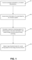
- FIG. 1 is a flow diagram of an electric vehicle energy management method based on bend prediction according to the present invention.
- an electric vehicle energy management method based on bend prediction includes the following steps:
- a current state of a supercapacitor is obtained, so remaining energy storage space E r of the supercapacitor is obtained (a known method is to perform conversion from an SOC state of the supercapacitor). if E r ⁇ 0.5E, it means that the remaining space of the supercapacitor may not be enough to recover energy which may be recovered due to braking before the vehicle enters a bend.
- S4 Adjust a logic threshold value for current driving based on the predicted energy recovery amount.
- the step specifically includes:
- the radius of curvature of the bend ahead is acquired based on the e-horizon system, and a predictive dynamic logic threshold value is generated, so that the defect that a traditional fixed logic threshold value does not have predictive optimal energy management is overcome.
- An energy management system performs predictive energy management through energy management strategies based on the predictive dynamic logic threshold value, which plays a positive role in reducing energy consumption of electric vehicles, preventing battery loss, improving the economical efficiency of the vehicles, etc.
- An embodiment of the present invention further provides a terminal device.
- the terminal device includes a memory, a processor, and a computer program stored on the memory and capable of running on the processor.
- the processor when executing the computer program, implements steps S1 to S4 of the above-mentioned method.
- the terminal device may be a desktop computer, a laptop, a palm computer, a cloud server and other computing devices.
- the terminal device may include, but is not limited to, a processor and a memory.
- a person skilled in the art may appreciate that the above composition structure of the terminal device is only an example of the terminal device and does not constitute a limitation on the terminal device.
- the terminal device may include more or less components than the above, or a combination of some components, or different components, for example, the terminal device may also include input and output devices, network access devices, buses, etc., which are not limited by the embodiments of the present invention.
- the processor may be a central processing unit (CPU), or other general purpose processors, digital signal processors (DSPs), application specific integrated circuits (ASICs), field-programmable gate arrays (FPGAs) or other programmable logic devices, discrete gates or transistor logic devices, discrete hardware components, etc.
- the general purpose processors may be a microprocessor or any conventional processor, etc.
- the processor is a control center of the terminal device, and is connected to each part of the entire terminal device via various interfaces and lines.
- the memory may be used for storing the computer programs and/or modules, and the processor implements various functions by running or executing the computer programs and/or modules stored in the memory and by invoking data stored in the memory.
- the memory may primarily include a program storage region and a data storage region.
- the program storage region may store an operating system, and applications required for at least one function.
- the memory may include a high-speed random access memory, or a non-volatile memory, such as a hard disk, an internal memory, a plug-in hard disk, a smart media card (SMC), a secure digital (SD) card, a flash card, at least one disk memory device, a flash memory device, or other volatile solid-state memory devices.
- SMC smart media card
- SD secure digital
- An embodiment of the present invention further provides a computer-readable storage medium.
- the computer-readable storage medium has a computer program stored thereon, and the computer program, when executed by a processor, implements the steps S1 to S4 of the above method according to the embodiment of the present invention.
- the integrated modules/units of the terminal device may be stored in a computer-readable storage medium if they are implemented in the form of software functional units and sold or used as stand-alone products. Based on such understanding, the present invention may also implement all or part of the processes in steps S1 to S4 of the method in the above embodiment by instructing relevant hardware by means of a computer program.
- the computer program may be stored in a computer-readable storage medium, and the computer program, when executed by a processor, may implement the steps of each of the above method embodiments.
- the computer program includes a computer program code, and the computer program code may be in a form of source code, object code, executable file or some intermediate forms.
- the computer-readable medium may include: any entity or device capable of carrying the computer program code, a recording medium, a USB flash drive, a mobile hard disk drive, a diskette, a compact disk, a computer memory, a read-only memory (ROM), a random access memory (RAM), an electrical carrier signal, a telecommunication signal, and a software distribution medium, etc.
- the computer-readable medium may contain content which is subject to appropriate additions and subtractions as required by legislation and patent practice in jurisdictions, for example, in some jurisdictions, the computer-readable medium does not include the electrical carrier signal or the telecommunication signal in accordance with legislation and patent practice.
Landscapes
- Engineering & Computer Science (AREA)
- Transportation (AREA)
- Mechanical Engineering (AREA)
- Automation & Control Theory (AREA)
- Power Engineering (AREA)
- Physics & Mathematics (AREA)
- Mathematical Physics (AREA)
- Life Sciences & Earth Sciences (AREA)
- Sustainable Development (AREA)
- Sustainable Energy (AREA)
- Human Computer Interaction (AREA)
- Electric Propulsion And Braking For Vehicles (AREA)
Abstract
Description
- The present invention relates to the field of electric vehicles, in particular to an electric vehicle energy management method based on bend prediction, a terminal device, and a storage medium.
- An energy system of a modern pure electric vehicle is generally a B+C (B=power battery, C=supercapacitor) system. Energy recovery is firstly done by a supercapacitor with higher charging and discharging efficiency, while in energy output management, a traditional method is an energy management strategy based on logic threshold rules, that is, a power output demand below a logic threshold is provided by a lithium battery, and a power output demand over the logic threshold is provided by the supercapacitor. In this way, the characteristic that the supercapacitor is suitable for fast charging and discharging may be fully used, the lithium battery is effectively protected, and the service life of the lithium battery is prolonged. However, traditional energy management methods are generally not predictive, that is, energy management is not optimized in advance based on road conditions ahead of the vehicle. Therefore, although the logic threshold rules or other traditional energy management methods are often applicable at present, they are not necessarily optimal for future road conditions.
- The present invention aims to provide an electric vehicle energy management method based on bend prediction, a terminal device, and a storage medium to solve the above-mentioned problems. Therefore, the specific technical solutions adopted by the present invention are as follows:
According to one aspect of the present invention, an electric vehicle energy management method based on bend prediction is provided. The method includes the following steps: - S1. counting an average acceleration av of vehicle decelerations;
- S2. acquiring bend information of a road ahead by an e-horizon system;
- S3. calculating a maximum cornering speed of a vehicle based on the bend information, and predicting energy recovery amount during cornering; and
- S4. adjusting a logic threshold value for current driving based on the energy recovery amount.
- Further, step S3 specifically includes:
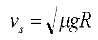
- S31. calculating the maximum cornering speed

- S32. predicting the energy recovery amount λE during cornering, where E denotes kinetic energy

- Further, Å ranges from 0.4 to 0.6.
- Further, step S4 specifically includes:
- S41. calculating a distance

- S42. calculating travel time


- S43. adjusting a logic threshold of the vehicle from D meters before the turn-in point to D2 meters before the turn-in point to PL -P, wherein PL is a conventional fixed logic threshold.
- Further, step S1 specifically includes: recording an acceleration ai of an ith vehicle deceleration based on a braking signal of the vehicle, and counting the average acceleration

- According to another aspect of the present invention, a terminal device is further provided. The terminal device includes a memory, a processor, and a computer program stored on the memory and capable of running on the processor, and the processor, when executing the computer program, implements the steps of the above-mentioned method.
- According to yet another aspect of the present invention, a computer-readable storage medium is further provided. The computer-readable storage medium has a computer program stored thereon, and the computer program, when executed by a processor, implements the steps of the above-mentioned method.
- By the adoption of the above technical solutions, the present invention has the following beneficial effects: With the method of the present invention, the supercapacitor can output more energy in advance based on energy likely to be recovered during cornering ahead, so as to free up energy recovery space and to recover energy during cornering, which can reduce power output of a battery, ensure energy recovery, and play a positive role in loss reduction and energy-saving control.
- To further illustrate the embodiments, the present invention is provided with accompanying drawings. The accompanying drawings are part of the disclosure of the present invention, are intended primarily to illustrate the embodiments, and may, together with relevant description of the specification, serve to explain the principles of operation of the embodiments. With these references in mind, a person of ordinary skill in the art will appreciate other possible embodiments and advantages of the present invention. Elements in the figures are not drawn to scale, and like reference numerals are generally used to indicate like elements.
-
FIG. 1 is a flow diagram of an electric vehicle energy management method based on bend prediction according to the present invention. - The present invention will now be further illustrated with reference to the accompanying drawings and the detailed description.
- As shown in
FIG. 1 , an electric vehicle energy management method based on bend prediction includes the following steps: - S1. Count an average acceleration av of vehicle decelerations. Specifically, an acceleration ai of an ith vehicle deceleration is recorded based on a braking signal of a vehicle, and the average acceleration

- S2. Acquire bend information of a road ahead by an e-horizon system.
- S3. Calculate a maximum cornering speed of the vehicle based on the bend information, and predict energy recovery amount during cornering. The step specifically includes:
- S31. Calculate the maximum cornering speed vs of the vehicle. The maximum cornering speed (also referred to as a limit sideslip speed) vs is calculated based on a formula

- S32. Predict the energy recovery amount during cornering. When the vehicle turns the corner, the current vehicle speed v0 may be reduced to be at least below the limit sideslip speed vs, so the kinetic energy that may be reduced during cornering relative to the current vehicle speed state of the vehicle is predicted to be at least

- S31. Calculate the maximum cornering speed vs of the vehicle. The maximum cornering speed (also referred to as a limit sideslip speed) vs is calculated based on a formula
- A current state of a supercapacitor is obtained, so remaining energy storage space Er of the supercapacitor is obtained (a known method is to perform conversion from an SOC state of the supercapacitor). if Er<0.5E, it means that the remaining space of the supercapacitor may not be enough to recover energy which may be recovered due to braking before the vehicle enters a bend.
- S4: Adjust a logic threshold value for current driving based on the predicted energy recovery amount. The step specifically includes:
- S41. Calculate a distance D2 between a position where the deceleration theoretically starts and a turn-in point as:

- S42. Ideally, completely recover the kinetic energy reduced for achieving safe cornering by the supercapacitor, which is the most economical. The travel time of the vehicle traveling to a deceleration point before the vehicle enters the bend is


- S43. Assuming that a conventional fixed logic threshold is PL , adjust a logic threshold of the vehicle within a distance from D meters before the turn-in point to D2 meters before the turn-in point to PL-P. in this way, more energy can be output by the supercapacitor before the vehicle enters the bend, which not only reduces the discharge of a power battery, but also makes the supercapacitor free up approximately enough space to recover the energy for bend deceleration, thereby not only protecting the power battery, but also achieving good energy consumption economical efficiency of the whole vehicle.
- According to the present invention, the radius of curvature of the bend ahead is acquired based on the e-horizon system, and a predictive dynamic logic threshold value is generated, so that the defect that a traditional fixed logic threshold value does not have predictive optimal energy management is overcome. An energy management system performs predictive energy management through energy management strategies based on the predictive dynamic logic threshold value, which plays a positive role in reducing energy consumption of electric vehicles, preventing battery loss, improving the economical efficiency of the vehicles, etc.
- An embodiment of the present invention further provides a terminal device. The terminal device includes a memory, a processor, and a computer program stored on the memory and capable of running on the processor. The processor, when executing the computer program, implements steps S1 to S4 of the above-mentioned method.
- Further, the terminal device may be a desktop computer, a laptop, a palm computer, a cloud server and other computing devices. The terminal device may include, but is not limited to, a processor and a memory. A person skilled in the art may appreciate that the above composition structure of the terminal device is only an example of the terminal device and does not constitute a limitation on the terminal device. The terminal device may include more or less components than the above, or a combination of some components, or different components, for example, the terminal device may also include input and output devices, network access devices, buses, etc., which are not limited by the embodiments of the present invention.
- Further, the processor may be a central processing unit (CPU), or other general purpose processors, digital signal processors (DSPs), application specific integrated circuits (ASICs), field-programmable gate arrays (FPGAs) or other programmable logic devices, discrete gates or transistor logic devices, discrete hardware components, etc. The general purpose processors may be a microprocessor or any conventional processor, etc. The processor is a control center of the terminal device, and is connected to each part of the entire terminal device via various interfaces and lines.
- The memory may be used for storing the computer programs and/or modules, and the processor implements various functions by running or executing the computer programs and/or modules stored in the memory and by invoking data stored in the memory. The memory may primarily include a program storage region and a data storage region. The program storage region may store an operating system, and applications required for at least one function. In addition, the memory may include a high-speed random access memory, or a non-volatile memory, such as a hard disk, an internal memory, a plug-in hard disk, a smart media card (SMC), a secure digital (SD) card, a flash card, at least one disk memory device, a flash memory device, or other volatile solid-state memory devices.
- An embodiment of the present invention further provides a computer-readable storage medium. The computer-readable storage medium has a computer program stored thereon, and the computer program, when executed by a processor, implements the steps S1 to S4 of the above method according to the embodiment of the present invention.
- The integrated modules/units of the terminal device may be stored in a computer-readable storage medium if they are implemented in the form of software functional units and sold or used as stand-alone products. Based on such understanding, the present invention may also implement all or part of the processes in steps S1 to S4 of the method in the above embodiment by instructing relevant hardware by means of a computer program. The computer program may be stored in a computer-readable storage medium, and the computer program, when executed by a processor, may implement the steps of each of the above method embodiments. The computer program includes a computer program code, and the computer program code may be in a form of source code, object code, executable file or some intermediate forms. The computer-readable medium may include: any entity or device capable of carrying the computer program code, a recording medium, a USB flash drive, a mobile hard disk drive, a diskette, a compact disk, a computer memory, a read-only memory (ROM), a random access memory (RAM), an electrical carrier signal, a telecommunication signal, and a software distribution medium, etc. it should be noted that the computer-readable medium may contain content which is subject to appropriate additions and subtractions as required by legislation and patent practice in jurisdictions, for example, in some jurisdictions, the computer-readable medium does not include the electrical carrier signal or the telecommunication signal in accordance with legislation and patent practice.
- While the present invention has been particularly illustrated and described with references to the preferred embodiments, it will be understood by a person skilled in the art that all changes in form and details made to the present invention without departing from the spirit and scope of the present invention as defined by the appended claims fall within the protection scope of the present invention.
Claims (7)
- An electric vehicle energy management method based on bend prediction, characterized by comprising the following steps:S1. counting an average acceleration av of vehicle decelerations;S2. acquiring bend information of a road ahead by an e-horizon system;S3. calculating a maximum cornering speed of a vehicle based on the bend information, and predicting energy recovery amount during cornering; andS4. adjusting a logic threshold value for current driving based on the energy recovery amount.
- The method according to claim 1, characterized in that step S1 specifically comprises: recording an acceleration ai of an ith vehicle deceleration based on a braking signal of the vehicle, and counting the average acceleration

- The method according to claim 1, characterized in that step S3 specifically comprises:S31. calculating the maximum cornering speed
 S32. predicting the energy recovery amount λE during cornering, wherein E denotes kinetic energy
- The method according to claim 3, characterized in that Å ranges from 0.4 to 0.6.
- The method according to claim 3, characterized in that step S4 specifically comprises:S41. calculating a distance
 S42. calculating travel time
 S43. adjusting a logic threshold of the vehicle from D meters before the turn-in point to D2 meters before the turn-in point to PL -P, wherein PL is a conventional fixed logic threshold.
 - A terminal device, comprising a memory, a processor, and a computer program stored on the memory and capable of running on the processor, characterized in that the processor, when executing the computer program, implements the steps of the method according to any one of claims 1 to 5.
- A computer-readable storage medium having a computer program stored thereon, characterized in that the computer program, when executed by a processor, implements the steps of the method according to any one of claims 1 to 5.
Applications Claiming Priority (2)
| Application Number | Priority Date | Filing Date | Title |
|---|---|---|---|
| CN202011355461.2A CN114537216A (en) | 2020-11-27 | 2020-11-27 | Electric vehicle energy management method based on curve prediction, terminal device and storage medium |
| PCT/CN2021/108062 WO2022110849A1 (en) | 2020-11-27 | 2021-07-23 | Curve prediction-based electric vehicle energy management method, terminal device, and storage medium |
Publications (2)
| Publication Number | Publication Date |
|---|---|
| EP4253137A1 true EP4253137A1 (en) | 2023-10-04 |
| EP4253137A4 EP4253137A4 (en) | 2024-11-13 |
Family
ID=81668192
Family Applications (1)
| Application Number | Title | Priority Date | Filing Date |
|---|---|---|---|
| EP21896356.9A Pending EP4253137A4 (en) | 2020-11-27 | 2021-07-23 | CURVE PREDICTION-BASED METHOD FOR ENERGY MANAGEMENT OF AN ELECTRIC VEHICLE, TERMINAL DEVICE AND STORAGE MEDIUM |
Country Status (4)
| Country | Link |
|---|---|
| US (1) | US20240025422A1 (en) |
| EP (1) | EP4253137A4 (en) |
| CN (1) | CN114537216A (en) |
| WO (1) | WO2022110849A1 (en) |
Families Citing this family (3)
| Publication number | Priority date | Publication date | Assignee | Title |
|---|---|---|---|---|
| CN118457593B (en) * | 2024-06-21 | 2025-06-24 | 东风商用车有限公司 | Vehicle fuel-saving control method and device in curve scene |
| US12269454B1 (en) | 2024-11-06 | 2025-04-08 | Finn Heath | Aftermarket hybrid conversion system for vehicles |
| CN120817052B (en) * | 2025-09-18 | 2025-12-02 | 杭州科技职业技术学院 | New energy automobile machine system and energy feedback control method |
Family Cites Families (12)
| Publication number | Priority date | Publication date | Assignee | Title |
|---|---|---|---|---|
| JP2001268719A (en) * | 2000-03-23 | 2001-09-28 | Toyota Motor Corp | Battery charging controller for hybrid vehicle |
| US9061599B2 (en) * | 2013-01-11 | 2015-06-23 | Johnson Controls Technology Company | System and method for optimizing the storing of vehicular energy |
| JP2015073347A (en) * | 2013-10-02 | 2015-04-16 | ダイムラー・アクチェンゲゼルシャフトDaimler AG | Electric-vehicular travel control apparatus |
| US9248756B2 (en) * | 2014-03-07 | 2016-02-02 | Ford Global Technologies, Llc | Plug-in vehicle eco charging mode |
| CN104290747B (en) * | 2014-03-17 | 2017-02-15 | 郑州宇通客车股份有限公司 | Composite power energy distributing method of hybrid vehicle |
| KR20150133539A (en) * | 2014-05-20 | 2015-11-30 | 현대자동차주식회사 | Regenerative braking method for vehicle and apparatus of the same |
| US9815373B2 (en) * | 2015-02-23 | 2017-11-14 | Ford Global Technologies, Llc | Battery state of charge target based on predicted regenerative energy |
| JP6436071B2 (en) * | 2015-12-07 | 2018-12-12 | 株式会社デンソー | Vehicle control device |
| GB2572448B (en) * | 2018-03-30 | 2021-02-03 | Jaguar Land Rover Ltd | Vehicle control method and apparatus |
| CN108512239B (en) * | 2018-05-10 | 2021-04-20 | 安徽大学 | Hybrid energy source system for electric vehicle and control strategy thereof |
| US11235665B2 (en) * | 2019-03-26 | 2022-02-01 | Ford Global Technologies, Llc | Regenerative braking control system |
| CN110936947A (en) * | 2019-11-22 | 2020-03-31 | 中国第一汽车股份有限公司 | Control method, device, equipment and medium for hybrid electric vehicle |
-
2020
- 2020-11-27 CN CN202011355461.2A patent/CN114537216A/en active Pending
-
2021
- 2021-07-23 EP EP21896356.9A patent/EP4253137A4/en active Pending
- 2021-07-23 US US18/254,119 patent/US20240025422A1/en active Pending
- 2021-07-23 WO PCT/CN2021/108062 patent/WO2022110849A1/en not_active Ceased
Also Published As
| Publication number | Publication date |
|---|---|
| US20240025422A1 (en) | 2024-01-25 |
| WO2022110849A1 (en) | 2022-06-02 |
| EP4253137A4 (en) | 2024-11-13 |
| CN114537216A (en) | 2022-05-27 |
Similar Documents
| Publication | Publication Date | Title |
|---|---|---|
| EP4253137A1 (en) | Curve prediction-based electric vehicle energy management method, terminal device, and storage medium | |
| CN112613680B (en) | Method, device, equipment and storage medium for estimating endurance mileage | |
| US12420661B2 (en) | Energy management method and terminal device for electric vehicle, and storage medium | |
| US20260031642A1 (en) | Method for dynamically adjusting power, and battery management system, device, medium and vehicle | |
| CN111583713B (en) | Vehicle driving early warning method and device | |
| CN110936947A (en) | Control method, device, equipment and medium for hybrid electric vehicle | |
| CN116749834B (en) | Energy monitoring method and device for range-extended automobile | |
| CN115503494B (en) | Single-pedal vehicle control method, vehicle control terminal and single-pedal vehicle | |
| CN114261397B (en) | Method, device and storage medium for estimating load state of commercial vehicle | |
| EP4257440A1 (en) | Vehicle-following distance control method based on terrain, and terminal device and storage medium | |
| WO2024082300A1 (en) | Energy recovery method, apparatus, device, readable storage medium and vehicle | |
| CN118928072A (en) | A method, device, equipment and medium for distributing power of a vehicle power system | |
| CN118545019A (en) | Hybrid electric vehicle control method and device, storage medium and vehicle | |
| CN113954639A (en) | Motor wheel end torque capacity determination method and device, electronic equipment and storage medium | |
| CN116862044A (en) | Method, device, medium and equipment for predicting charging power load of bus charging station | |
| CN113280901B (en) | Method and device for determining vehicle load | |
| CN116620256B (en) | Energy control method, device and vehicle | |
| CN117841965B (en) | Control method and device for range extender at corresponding time after vehicle operating parameters are lost | |
| EP4183652B1 (en) | Hydraulic hybrid vehicle power control method, terminal device and storage medium | |
| CN117261623B (en) | Range extender control method, device, electronic device and storage medium | |
| CN117124925A (en) | A pure electric mileage prediction method, device, electronic equipment and storage medium | |
| CN117360476A (en) | Hybrid vehicle power control method, device, equipment and vehicle | |
| CN112560279B (en) | Vehicle overtaking collision risk probability estimation method, terminal equipment and storage medium | |
| CN116587926B (en) | New energy vehicle electric quantity display control method and device, vehicle and storage medium | |
| CN118731810A (en) | A method and device for identifying electric quantity, a computer-readable storage medium and an electric vehicle |
Legal Events
| Date | Code | Title | Description |
|---|---|---|---|
| STAA | Information on the status of an ep patent application or granted ep patent |
Free format text: STATUS: THE INTERNATIONAL PUBLICATION HAS BEEN MADE |
|
| PUAI | Public reference made under article 153(3) epc to a published international application that has entered the european phase |
Free format text: ORIGINAL CODE: 0009012 |
|
| STAA | Information on the status of an ep patent application or granted ep patent |
Free format text: STATUS: REQUEST FOR EXAMINATION WAS MADE |
|
| 17P | Request for examination filed |
Effective date: 20230331 |
|
| AK | Designated contracting states |
Kind code of ref document: A1 Designated state(s): AL AT BE BG CH CY CZ DE DK EE ES FI FR GB GR HR HU IE IS IT LI LT LU LV MC MK MT NL NO PL PT RO RS SE SI SK SM TR |
|
| DAV | Request for validation of the european patent (deleted) | ||
| DAX | Request for extension of the european patent (deleted) | ||
| RAP3 | Party data changed (applicant data changed or rights of an application transferred) |
Owner name: XIAMEN YAXON ZHILIAN TECHNOLOGY CO., LTD. |
|
| A4 | Supplementary search report drawn up and despatched |
Effective date: 20241016 |
|
| RIC1 | Information provided on ipc code assigned before grant |
Ipc: B60W 50/00 20060101ALI20241010BHEP Ipc: B60W 40/12 20120101ALI20241010BHEP Ipc: B60W 30/18 20120101ALI20241010BHEP Ipc: B60L 58/12 20190101AFI20241010BHEP |
|
| STAA | Information on the status of an ep patent application or granted ep patent |
Free format text: STATUS: EXAMINATION IS IN PROGRESS |
|
| 17Q | First examination report despatched |
Effective date: 20250905 |
|
| GRAP | Despatch of communication of intention to grant a patent |
Free format text: ORIGINAL CODE: EPIDOSNIGR1 |
|
| STAA | Information on the status of an ep patent application or granted ep patent |
Free format text: STATUS: GRANT OF PATENT IS INTENDED |