EP4253119A1 - Support structure for electric component - Google Patents
Support structure for electric component Download PDFInfo
- Publication number
- EP4253119A1 EP4253119A1 EP23157429.4A EP23157429A EP4253119A1 EP 4253119 A1 EP4253119 A1 EP 4253119A1 EP 23157429 A EP23157429 A EP 23157429A EP 4253119 A1 EP4253119 A1 EP 4253119A1
- Authority
- EP
- European Patent Office
- Prior art keywords
- bracket
- electric component
- inverter
- transmission case
- transmission
- Prior art date
- Legal status (The legal status is an assumption and is not a legal conclusion. Google has not performed a legal analysis and makes no representation as to the accuracy of the status listed.)
- Granted
Links
Images



Classifications
-
- B—PERFORMING OPERATIONS; TRANSPORTING
- B60—VEHICLES IN GENERAL
- B60K—ARRANGEMENT OR MOUNTING OF PROPULSION UNITS OR OF TRANSMISSIONS IN VEHICLES; ARRANGEMENT OR MOUNTING OF PLURAL DIVERSE PRIME-MOVERS IN VEHICLES; AUXILIARY DRIVES FOR VEHICLES; INSTRUMENTATION OR DASHBOARDS FOR VEHICLES; ARRANGEMENTS IN CONNECTION WITH COOLING, AIR INTAKE, GAS EXHAUST OR FUEL SUPPLY OF PROPULSION UNITS IN VEHICLES
- B60K5/00—Arrangement or mounting of internal-combustion or jet-propulsion units
- B60K5/04—Arrangement or mounting of internal-combustion or jet-propulsion units with the engine main axis, e.g. crankshaft axis, transversely to the longitudinal centre line of the vehicle
-
- B—PERFORMING OPERATIONS; TRANSPORTING
- B60—VEHICLES IN GENERAL
- B60K—ARRANGEMENT OR MOUNTING OF PROPULSION UNITS OR OF TRANSMISSIONS IN VEHICLES; ARRANGEMENT OR MOUNTING OF PLURAL DIVERSE PRIME-MOVERS IN VEHICLES; AUXILIARY DRIVES FOR VEHICLES; INSTRUMENTATION OR DASHBOARDS FOR VEHICLES; ARRANGEMENTS IN CONNECTION WITH COOLING, AIR INTAKE, GAS EXHAUST OR FUEL SUPPLY OF PROPULSION UNITS IN VEHICLES
- B60K1/00—Arrangement or mounting of electrical propulsion units
-
- B—PERFORMING OPERATIONS; TRANSPORTING
- B60—VEHICLES IN GENERAL
- B60K—ARRANGEMENT OR MOUNTING OF PROPULSION UNITS OR OF TRANSMISSIONS IN VEHICLES; ARRANGEMENT OR MOUNTING OF PLURAL DIVERSE PRIME-MOVERS IN VEHICLES; AUXILIARY DRIVES FOR VEHICLES; INSTRUMENTATION OR DASHBOARDS FOR VEHICLES; ARRANGEMENTS IN CONNECTION WITH COOLING, AIR INTAKE, GAS EXHAUST OR FUEL SUPPLY OF PROPULSION UNITS IN VEHICLES
- B60K5/00—Arrangement or mounting of internal-combustion or jet-propulsion units
- B60K5/12—Arrangement of engine supports
- B60K5/1208—Resilient supports
- B60K5/1216—Resilient supports characterised by the location of the supports relative to the motor or to each other
-
- B—PERFORMING OPERATIONS; TRANSPORTING
- B60—VEHICLES IN GENERAL
- B60Y—INDEXING SCHEME RELATING TO ASPECTS CROSS-CUTTING VEHICLE TECHNOLOGY
- B60Y2200/00—Type of vehicle
- B60Y2200/90—Vehicles comprising electric prime movers
- B60Y2200/92—Hybrid vehicles
-
- B—PERFORMING OPERATIONS; TRANSPORTING
- B60—VEHICLES IN GENERAL
- B60Y—INDEXING SCHEME RELATING TO ASPECTS CROSS-CUTTING VEHICLE TECHNOLOGY
- B60Y2400/00—Special features of vehicle units
- B60Y2400/61—Arrangements of controllers for electric machines, e.g. inverters
-
- B—PERFORMING OPERATIONS; TRANSPORTING
- B60—VEHICLES IN GENERAL
- B60Y—INDEXING SCHEME RELATING TO ASPECTS CROSS-CUTTING VEHICLE TECHNOLOGY
- B60Y2410/00—Constructional features of vehicle sub-units
- B60Y2410/10—Housings
-
- F—MECHANICAL ENGINEERING; LIGHTING; HEATING; WEAPONS; BLASTING
- F16—ENGINEERING ELEMENTS AND UNITS; GENERAL MEASURES FOR PRODUCING AND MAINTAINING EFFECTIVE FUNCTIONING OF MACHINES OR INSTALLATIONS; THERMAL INSULATION IN GENERAL
- F16H—GEARING
- F16H57/00—General details of gearing
- F16H57/02—Gearboxes; Mounting gearing therein
- F16H2057/02026—Connection of auxiliaries with a gear case; Mounting of auxiliaries on the gearbox
-
- F—MECHANICAL ENGINEERING; LIGHTING; HEATING; WEAPONS; BLASTING
- F16—ENGINEERING ELEMENTS AND UNITS; GENERAL MEASURES FOR PRODUCING AND MAINTAINING EFFECTIVE FUNCTIONING OF MACHINES OR INSTALLATIONS; THERMAL INSULATION IN GENERAL
- F16H—GEARING
- F16H57/00—General details of gearing
- F16H57/02—Gearboxes; Mounting gearing therein
- F16H2057/0203—Gearboxes; Mounting gearing therein the gearbox is associated or combined with a crank case of an engine
Definitions
- the engine 2 includes a cylinder block 4, a cylinder head 5 attached to an upper part of the cylinder block 4, a cylinder head cover 6 attached to an upper part of the cylinder head 5, and an oil pan (not illustrated) attached to a lower part of the cylinder block 4.
- a pair of front fastening parts 23c, a pair of rear fastening parts 23d, and a left fastening part 23e are provided in the lower bracket 23.
Landscapes
- Engineering & Computer Science (AREA)
- Chemical & Material Sciences (AREA)
- Combustion & Propulsion (AREA)
- Transportation (AREA)
- Mechanical Engineering (AREA)
- Arrangement Or Mounting Of Propulsion Units For Vehicles (AREA)
- Hybrid Electric Vehicles (AREA)
- Cylinder Crankcases Of Internal Combustion Engines (AREA)
- Inverter Devices (AREA)
Abstract
Description
- The present invention relates to a support structure for an electric component.
- Conventionally, a hybrid vehicle power plant has been known in which an inverter (electric component) is installed directly above a transaxle casing and the inverter is connected to the transaxle casing via a bracket (see
WO2012/114491 ). - [Patent Literature 1]
WO2012/114491 - However, in the conventional hybrid vehicle power plant, in a case where a distance between the inverter and the transaxle casing is long, when the transaxle is extended toward the inverter and connected to the inverter, stiffness in coupling between the inverter and the casing may be reduced, and stiffness in support of the inverter with respect to the casing may be reduced. Hence, it is difficult to curb vibration of the inverter.
- The present invention has been made by focusing attention on the above circumstances, and aims to provide a support structure for an electric component that, even when a distance between the electric component installed directly above a transmission case and a transmission is long, can enhance stiffness in support of the electric component with respect to the transmission and can curb vibration of the electric component.
- The present invention is a support structure for an electric component installed directly above a transmission case of a transmission that changes a speed of rotation of an internal combustion engine, the support structure being characterized by including a first bracket connected to the electric component, and a second bracket connected to the transmission case, in which, by connecting the first bracket and the second bracket, the electric component is connected to the transmission case via the first bracket and the second bracket.
- As described above, according to the present invention, it is possible to, even when a distance between the electric component installed directly above a transmission case and a transmission is long, enhance stiffness in support of the electric component with respect to the transmission and curb vibration of the electric component.
-
- [
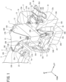
Figure 1] Figure 1 is a perspective view of an internal combustion engine and a transmission including a support structure for an electric component according to an example of the present invention. - [
Figure 2] Figure 2 is a front view of the internal combustion engine and the transmission including the support structure for the electric component according to the example. - [
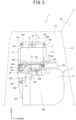
Figure 3] Figure 3 is a left side view of the internal combustion engine and the transmission including the support structure for the electric component according to the example. - [
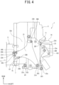
Figure 4] Figure 4 is a top view of the internal combustion engine and the transmission including the support structure for the electric component according to the example. - [
Figure 5] Figure 5 is a top view of the transmission including the support structure for the electric component according to the example, and illustrates a state where an upper bracket, an inverter, and a lower bracket are removed from the transmission. - [
Figure 6] Figure 6 is a top view of the transmission including the support structure for the electric component according to the example, and illustrates a state where the upper bracket and the inverter are removed. - [
Figure 7] Figure 7 is a diagram illustrating the support structure for the electric component according to the example of the present invention, and is an enlarged perspective view of a connection part of the upper bracket and a middle bracket. - A support structure for an electric component according to an embodiment of the present invention is a support structure for the electric component installed directly above a transmission case of a transmission that changes a speed of rotation of an internal combustion engine, the support structure including a first bracket connected to the electric component, and a second bracket connected to the transmission case, in which by connecting the first bracket and the second bracket, the electric component is connected to the transmission case via the first bracket and the second bracket.
- With this configuration, the support structure for the electric component according to the embodiment of the present invention can, even when a distance between the electric component installed directly above a transmission case and a transmission is long, enhance stiffness in support of the electric component with respect to the transmission and curb vibration of the electric component.
- Hereinafter, a support structure for an electric component according to an example of the present invention will be described with reference to the drawings.
-
Figures 1 to 7 are diagrams illustrating the support structure for the electric component according to the example of the present invention. InFigures 1 to 7 , upper and lower, front and rear, and left and right directions are based on an internal combustion engine and a transmission installed in a vehicle, and a front-rear direction of the vehicle is referred to as the front-rear direction, a left-right direction of the vehicle (width direction of vehicle) is referred to as the left-right direction, and an up-down direction of the vehicle (height direction of vehicle) is referred to as the up-down direction. - First, a configuration will be described.
- In
Figures 1 and2 , anengine 2 as an internal combustion engine and atransmission 3 are installed in anengine compartment 1a of a vehicle 1 (seeFigure 3 ). As illustrated inFigure 3 , the vehicle 1 includes a dash panel 1A, theengine compartment 1a is formed in front of the dash panel 1A, and avehicle interior 1b in which occupants including a driver ride is formed behind the dash panel 1A. - As illustrated in
Figure 2 , theengine 2 includes acylinder block 4, acylinder head 5 attached to an upper part of thecylinder block 4, acylinder head cover 6 attached to an upper part of thecylinder head 5, and an oil pan (not illustrated) attached to a lower part of thecylinder block 4. - A
crankshaft 4a is provided in thecylinder block 4, and thecrankshaft 4a extends in the width direction of the vehicle (hereinafter also referred to as a vehicle width direction). Theengine 2 of the present example is a transverse engine. - As illustrated in
Figures 1 and4 ,EGR piping 7 is provided in thecylinder head 5. TheEGR piping 7 is provided in an upper part of thecylinder head 5 to extend in the front-rear direction of the vehicle 1, and includes therein anEGR passage 7a that allows passage of an EGR gas (seeFigure 7 ). - An exhaust component (not illustrated) is installed on the front side of the
engine 2, and the EGR gas flows into a front end part of theEGR passage 7a from the exhaust component. An intake component (not illustrated) is installed on the rear side of theengine 2, and the EGR gas discharged from a rear end part of theEGR passage 7a is discharged into the intake component. - A
transmission case 10 is connected to thecylinder block 4 of theengine 2, and changes the speed of and outputs a drive force (rotation) transmitted from thecrankshaft 4a. - The
engine 2 and thetransmission 3 are installed next to each other in the vehicle width direction, and thetransmission 3 is installed in a part lower than thecylinder head 5. In other words, theengine 2 and thetransmission 3 overlap in the front-rear direction. - The
transmission 3 includes thetransmission case 10, and a transmission mechanism, a differential device, and the like including components such as transmission gears (not illustrated) are installed in thetransmission case 10. - As illustrated in
Figures 1 and4 , aninverter 11 as the electric component is installed directly above thetransmission case 10. Theinverter 11 converts DC power supplied from a battery (not illustrated) into three-phase AC power and supplies the three-phase AC power to a motor generator, and converts three-phase AC power generated by the motor generator into DC power and charges a battery with the DC power. - As illustrated in
Figure 4 , theinverter 11 is installed directly above thetransmission case 10 such that its longer direction is oriented in the front-rear direction of the vehicle 1 and its shorter direction is oriented in the vehicle width direction. - As illustrated in
Figure 2 , theinverter 11 has anupper wall 12, alower wall 13, afront wall 14, a rear wall 15 (seeFigure 1 ), aleft wall 16, and aright wall 17. - As illustrated in
Figure 1 , anupper bracket 21 is connected to theupper wall 12 of theinverter 11. Theupper bracket 21 is connected to thecylinder head 5 via amiddle bracket 22. - In other words, the
inverter 11 is connected to thecylinder head 5 via theupper bracket 21. Theupper bracket 21 of the present example forms a support member. - The
middle bracket 22 has ahorizontal wall part 22A and avertical wall part 22B. As illustrated inFigures 4 and7 , thehorizontal wall part 22A is fastened to theEGR piping 7 in the up-down direction with abolt 20A. Specifically, thehorizontal wall part 22A is connected to a central part in the front-rear direction of anupper wall 7b of theEGR piping 7. - The
vertical wall part 22B extends downward from a left end part in the vehicle width direction of thehorizontal wall part 22A, and is fastened to aleft side wall 5a of thecylinder head 5 in the horizontal direction with abolt 20B (seeFigures 1 and2 ). Theleft side wall 5a of thecylinder head 5 faces thetransmission 3 in the vehicle width direction. - In the present example, the
upper wall 7b of theEGR piping 7 forms an upper wall of an internal combustion engine, and theleft side wall 5a of thecylinder head 5 forms a side wall of the internal combustion engine. - As illustrated in
Figure 4 , when thetransmission 3 is viewed from above, theupper bracket 21 is formed in a triangular shape and theinverter 11 is formed in a rectangular shape. - Fastening
parts upper bracket 21, and thefastening parts bolts - As illustrated in
Figure 1 , fastenedparts upper wall 12 of theinverter 11. - Specifically, the fastened
part 12A is provided in a left end part of the front end part of theupper wall 12, and the fastenedpart 12B is provided in a right end part of the rear end part of theupper wall 12 located diagonally opposite to the fastenedpart 12A. - The fastening
part 21A of theupper bracket 21 is fastened to the fastenedpart 12A of theupper wall 12 of theinverter 11 with abolt 20C, and the fasteningpart 21B of theupper bracket 21 is fastened to the fastenedpart 12B of theupper wall 12 of theinverter 11 with abolt 20D. - As a result, the
upper bracket 21 is fastened to the front end part and the rear end part of theupper wall 12 of theinverter 11 which are separated in the front-rear direction. - As illustrated in
Figures 1 and2 , a fastenedpart 22a is provided in thehorizontal wall part 22A of themiddle bracket 22, and the fastening part 21C of theupper bracket 21 is fastened to the fastenedpart 22a of thehorizontal wall part 22A of themiddle bracket 22 in the up-down direction with abolt 20E. - As illustrated in
Figure 2 , the fastenedpart 22a is provided between aright end part 22c (right end part 22c ofhorizontal wall part 22A) of themiddle bracket 22 and aleft end part 22d (left end part 22d ofvertical wall part 22B) of themiddle bracket 22 in the vehicle width direction. - As illustrated in
Figure 1 , alower bracket 23 is connected to thelower wall 13 of theinverter 11, and theinverter 11 is connected to anupper wall 10A of thetransmission case 10 by thelower bracket 23. - The
lower bracket 23 of the present example forms the first bracket, and themiddle bracket 22 forms a third bracket. - As illustrated in
Figure 6 , a flat-plate-shapedplacement part 23A on which theinverter 11 is placed is provided in thelower bracket 23, and a pair of front fastenedparts 23a and a pair of rear fastenedparts 23b are provided in theplacement part 23A. - The front fastened
part 23a is provided in a front end part of theplacement part 23A, and the rear fastenedpart 23b is provided in a rear end part of theplacement part 23A. - A front end part of the
lower wall 13 of theinverter 11 is fastened to the front fastenedparts 23a with bolts (not illustrated), and a rear end part of thelower wall 13 of theinverter 11 is fastened to the rear fastenedparts 23b with bolts (not illustrated). - A pair of
front fastening parts 23c, a pair ofrear fastening parts 23d, and aleft fastening part 23e are provided in thelower bracket 23. - The
front fastening part 23c is provided in a front end part of theplacement part 23A and protrudes downward from theplacement part 23A (seeFigure 2 ). - The
rear fastening part 23d is provided in a rear end part of theplacement part 23A and protrudes downward from theplacement part 23A (seeFigure 3 ). Theleft fastening part 23e extends leftward and downward from a left end part of theplacement part 23A to be located leftward of theleft wall 16 of the inverter 11 (seeFigures 1 and3 ). - As illustrated in
Figure 4 , theleft fastening part 23e, theinverter 11, and theengine 2 are installed next to one another in the vehicle width direction in the order of theleft fastening part 23e, theinverter 11, and theengine 2. Theleft fastening part 23e of the present example forms a fastening part on one side. - As illustrated in
Figure 5 , a pair of fastenedparts 10a are provided in theupper wall 10A of thetransmission case 10, and therear fastening parts 23d of thelower bracket 23 are fastened to the fastenedparts 10a in the up-down direction withbolts 20F (seeFigure 6 ). - As illustrated in
Figures 1 and3 , amiddle bracket 24 is connected to thetransmission case 10, and as illustrated inFigure 3 , themiddle bracket 24 includes ahorizontal wall part 24A and avertical wall part 24B. - As illustrated in
Figure 5 , anupper fastening part 24a is provided in thehorizontal wall part 24A, and theupper fastening part 24a is fastened to theupper wall 10A of thetransmission case 10 in the up-down direction with abolt 20G (seeFigure 3 ). - As illustrated in
Figure 3 , thevertical wall part 24B extends downward along afront wall 10B of thetransmission case 10 from a front end part of thehorizontal wall part 24A. That is, thevertical wall part 24B extends in the up-down direction along thefront wall 10B of thetransmission case 10. Thefront wall 10B of the present example forms a side wall of the transmission case. - As illustrated in
Figure 2 ,lower fastening parts Figure 3 ) are provided in thevertical wall part 24B, and thelower fastening parts front wall 10B of thetransmission case 10 in the horizontal direction withbolts 20H. - The
front fastening part 23c,rear fastening part 23d, and leftfastening part 23e of the present example form a first fastening part, and thelower fastening parts Bolts bolt 20H forms a second fastener. - As illustrated in
Figure 5 , a pair offastening parts 24e are provided in thehorizontal wall part 24A of themiddle bracket 24, and thefront fastening parts 23c of theplacement part 23A are fastened to the pair offastening parts 24e in the up-down direction with bolts 20I (seeFigure 6 ). Themiddle bracket 24 of the present example forms a second bracket. - As illustrated in
Figure 5 , a mount attachment part 10C is provided in a left end part of theupper wall 10A of thetransmission case 10. - One end part of a
mount bracket 25 is fastened to the mount attachment part 10C withbolts 20J. - The other end part of the
mount bracket 25 is elastically supported to aleft side member 27 by anelastic body unit 26. Themount bracket 25 and theelastic body unit 26 form amount device 28. Theleft side member 27 of the present example forms a vehicle body. - With this configuration, the
transmission 3 is elastically supported to theleft side member 27 via themount device 28. On the other hand, theengine 2 is elastically supported to a right side member (not illustrated) by a mount device (not illustrated). - As illustrated in
Figure 5 , afastening part 10c is provided in the mount attachment part 10C, and thelower fastening part 23e of thelower bracket 23 is fastened to thefastening part 10c in the up-down direction with abolt 20K (seeFigure 6 ). - As described above, the
lower bracket 23 of the present example is connected to theupper wall 10A of thetransmission case 10, themiddle bracket 24, and the mount attachment part 10C, and theinverter 11 is connected to theupper wall 10A of thetransmission case 10, themiddle bracket 24, and the mount attachment part 10C via thelower bracket 23. - As illustrated in
Figure 3 , acomponent 30 forming a part of thetransmission 3 is attached to theupper wall 10A of thetransmission case 10, and thehorizontal wall part 24A of themiddle bracket 24 is installed in a part higher than thecomponent 30. - In other words, the
component 30 having a certain height is installed in theupper wall 10A of thetransmission case 10 of the present example. For this reason, when the front side of thelower bracket 23 interferes with thecomponent 30 and cannot connect directly with thetransmission case 10, thelower bracket 23 can be connected to themiddle bracket 24 to connect theinverter 11 to thetransmission case 10 via thelower bracket 23 and themiddle bracket 24. - Note that while functions and the like of the
component 30 are not described in detail, any component may be used as long as the component is included as a part of thetransmission 3. - Next, effects of the support structure for the
inverter 11 of the present example will be described. - The support structure for the
inverter 11 of the present example has theinverter 11 installed directly above thetransmission case 10, thelower bracket 23 connected to thelower wall 13 of theinverter 11, and themiddle bracket 24 connected to thetransmission case 10. By connecting thelower bracket 23 and themiddle bracket 24, theinverter 11 is connected to thetransmission case 10 via thelower bracket 23 and themiddle bracket 24. - As a result, even when the distance between the
transmission case 10 and theinverter 11 is long, theinverter 11 can be connected to thetransmission case 10 via thelower bracket 23 and themiddle bracket 24. - For this reason, it is possible to enhance stiffness in coupling between the
inverter 11 and thetransmission case 10 by thelower bracket 23 and themiddle bracket 24, and prevent reduction of stiffness in support of theinverter 11 with respect to thetransmission case 10. As a result, it is possible to curb vibration of theinverter 11. - Additionally, even when the
component 30 is installed on theupper wall 10A of thetransmission case 10, thelower bracket 23 and themiddle bracket 24 can prevent interference of theinverter 11 with thecomponent 30 and also enable installation of theinverter 11 directly above thetransmission case 10 to improve the degree of freedom of installation of theinverter 11. - Additionally, according to the support structure for the
inverter 11 of the present example, thelower bracket 23 has therear fastening part 23d fastened to theupper wall 10A of thetransmission case 10 in the up-down direction with thebolt 20F, thefront fastening part 23c fastened to themiddle bracket 24 in the up-down direction with the bolt 20I, and theleft fastening part 23e fastened to the mount attachment part 10C of thetransmission case 10 in the up-down direction with thebolt 20K. - Additionally, the
middle bracket 24 to which thelower bracket 23 is connected has thevertical wall part 24B extending in the up-down direction along thefront wall 10B of thetransmission case 10, and thelower fastening parts vertical wall part 24B and fastened to thefront wall 10B of thetransmission case 10 in the horizontal direction with thebolts 20H. - With this configuration, by connecting the
lower bracket 23 to theupper wall 10A of thetransmission case 10 and connecting themiddle bracket 24 to thefront wall 10B orthogonal to theupper wall 10A, it is possible to increase the attachment strength of thelower bracket 23 and themiddle bracket 24 with respect to thetransmission case 10 and enhance stiffness of thelower bracket 23 and themiddle bracket 24. - For this reason, by connecting the
inverter 11 to thelower bracket 23 andmiddle bracket 24 having high stiffness, stiffness in support of theinverter 11 can be enhanced even more, and vibration of theinverter 11 can be curbed more effectively. - Additionally, according to the support structure for the
inverter 11 of the present example, theinverter 11 is fastened to the front fastenedparts 23a located in the front end part of thelower bracket 23 and the rear fastenedparts 23b located in the rear end part of thelower bracket 23. - The
lower bracket 23 is fastened to thetransmission case 10 via thefront fastening parts 23c located in the front end part of thetransmission case 10, therear fastening parts 23d located in the rear end part of thetransmission case 10, and theleft fastening part 23e located on the left side of theinverter 11, and theleft fastening part 23e, theinverter 11, and theengine 2 are installed next to one another in the vehicle width direction in the order of theleft fastening part 23e, theinverter 11, and theengine 2. - With this configuration, it is possible to connect the
lower bracket 23 to which theinverter 11 is connected with thetransmission case 10 in a wider range than the area of thelower wall 13 of theinverter 11, and enhance stiffness in support of theinverter 11 with respect to thetransmission case 10 even more. - Additionally, since the
lower bracket 23 is connected with thetransmission case 10 in a longer range than the length in the vehicle width direction of thelower wall 13 of theinverter 11, it is possible to curb vibration of theinverter 11 in the vehicle width direction more effectively. - Additionally, according to the support structure for the
inverter 11 of the present example, thetransmission case 10 has the mount attachment part 10C. - The mount attachment part 10C is connected to the
mount bracket 25 that connects thetransmission 3 to theleft side member 27, and theleft fastening part 23e is fastened to the mount attachment part 10C. - The mount attachment part 10C has the
mount bracket 25 fastened and connected thereto, and therefore has high stiffness. By providing thefastening part 10c in the mount attachment part 10C and connecting thelower bracket 23 to thefastening part 10c, the attachment strength of thelower bracket 23 can be increased. For this reason, it is possible to enhance stiffness in support of theinverter 11 with respect to thetransmission case 10 even more. - Additionally, since the
fastening part 10c farthest away from theengine 2 in the vehicle width direction is installed in the mount attachment part 10C having high stiffness and thelower bracket 23 is connected to thefastening part 10c, the attachment strength in the vehicle width direction of thelower bracket 23 with respect to thetransmission case 10 can be increased. For this reason, it is possible to curb vibration of theinverter 11 in the vehicle width direction more effectively. - Additionally, according to the support structure for the
inverter 11 of the present example, theinverter 11 is installed directly above thetransmission 3 such that its longer direction is oriented in the front-rear direction of the vehicle 1 and its shorter direction is oriented in the vehicle width direction, and is arranged next to theengine 2 in the vehicle width direction. - Moreover, the support structure for the
inverter 11 of the present example has theupper bracket 21 connected to theupper wall 12 of theinverter 11 and theengine 2, and theinverter 11 is connected to theengine 2 via theupper bracket 21. - With this configuration, the
upper wall 12 of theinverter 11 can be reinforced by theupper bracket 21 and also be supported by theupper bracket 21, so that vibration of theupper wall 12 of theinverter 11 can be curbed. - Additionally, since the
inverter 11 is installed directly above thetransmission 3 such that its longer direction is oriented in the front-rear direction of the vehicle 1 and its shorter direction is oriented in the vehicle width direction, vibration in the vehicle width direction is weaker than vibration in the front-rear direction. - According to the support structure for the
inverter 11 of the present example, theinverter 11 is installed next to theengine 2 in the vehicle width direction such that its longer direction is oriented in the front-rear direction and its shorter direction is oriented in the vehicle width direction, and theinverter 11 is connected to theengine 2 via theupper bracket 21. Hence, it is possible to curb vibration of theinverter 11 in the vehicle width direction. - Moreover, by connecting the
inverter 11 and theengine 2 by theupper bracket 21, it is possible to connect a vibration system including theengine 2 and a vibration system including thetransmission 3 by theupper bracket 21. - For this reason, it is possible to enhance stiffness in support of the
inverter 11 with respect to theengine 2 to combine the vibration systems, and curb vibration of theinverter 11 in the front-rear direction and the vehicle width direction. - As described above, the support structure for the
inverter 11 of the present example can enhance stiffness in support of theinverter 11 installed directly above thetransmission case 10 and can curb vibration of theinverter 11. - Additionally, the support structure for the
inverter 11 of the present example has themiddle bracket 22 connected to theupper wall 7b of theEGR piping 7 and theleft side wall 5a of thecylinder head 5 facing thetransmission 3 in the vehicle width direction. - The
upper bracket 21 is connected to themiddle bracket 22, and theinverter 11 is connected to theengine 2 via theupper bracket 21 and themiddle bracket 22. - With this configuration, it is possible to connect the
middle bracket 22 to two surfaces of theupper wall 7b of theEGR piping 7 and theleft side wall 5a of thecylinder head 5 orthogonal to theupper wall 7b of theEGR piping 7, to increase the attachment strength of themiddle bracket 22 to thecylinder head 5 and enhance stiffness of themiddle bracket 22. - For this reason, by connecting the
upper bracket 21 to themiddle bracket 22 having high stiffness, it is possible to enhance stiffness in support of theinverter 11 with respect to theengine 2 even more, and curb vibration of theinverter 11 more effectively. - Moreover, while the shape of the
upper bracket 21 may become complex when theupper bracket 21 is directly connected to theEGR piping 7, by connecting theupper bracket 21 to theEGR piping 7 and thecylinder head 5 via themiddle bracket 22, it is possible to simplify the shape of theupper bracket 21. - While an example of the present invention has been disclosed, it is clear that a person skilled in the art can make modifications without departing from the scope of the present invention. All such modifications and equivalents thereof are intended to be included in the claims below.
- 1...vehicle, 2...engine (internal combustion engine), 3...transmission, 5a...left side wall (side wall of internal combustion engine), 7b...upper wall (upper wall of internal combustion engine), 10...transmission case, 10A...upper wall (upper wall of transmission case), 10C...mount attachment part, 11...inverter (electric component), 20F, 20I, 20K...bolt (first fastener), 20H...bolt (second fastener), 21...upper bracket (support member), 22...middle bracket (third bracket), 23...lower bracket (first bracket), 23a...front fastened part, 23b...rear fastened part, 23c...front fastening part (first fastening part), 23d...rear fastening part (first fastening part), 23e...left fastening part (first fastening part, fastening part on one side), 24...middle bracket (second bracket), 24A...horizontal wall part, 24B...vertical wall part, 24b, 24c, 24d...lower fastening part (second fastening part), 25...mount bracket, 27...left side member (vehicle body)
Claims (6)
- A support structure for an electric component (11) installed directly above a transmission case (10) of a transmission (3) that changes a speed of rotation of an internal combustion engine (2), the support structure being characterized by (11) comprisinga first bracket (23) connected to the electric component (11), and a second bracket (24) connected to the transmission case (10), whereinby connecting the first bracket (23) and the second bracket (24), the electric component (11) is connected to the transmission case (10) via the first bracket (23) and the second bracket (24).
- The support structure for the electric component (11) as claimed in claim 1, whereinthe first bracket (23) has a first fastening part (23c, 23d, 23e) fastened to an upper wall (10A) of the transmission case (10) and the second bracket (24) in an up-down direction with a first fastener (20F, 20I, 20K), andthe second bracket (24) has a vertical wall part (24B) extending in the up-down direction along a side wall (10B) of the transmission case (10), and a second fastening part (24b, 24c, 24d) provided in the vertical wall part (24B) and fastened to the side wall (10B) of the transmission case (10) in a horizontal direction with a second fastener (20H).
- The support structure for the electric component (11) as claimed in claim 1 or 2, whereinthe electric component (11) is fastened to a front fastened part (23a) provided in a front end part of the first bracket (23) and a rear fastened part (23b) provided in a rear end part of the first bracket (23);the first bracket (23) is fastened to the transmission (3) via a front fastening part (23c) provided in a front end part of the first bracket (23), a rear fastening part (23d) provided in a rear end part of the first bracket (23), and a fastening part on one side (23e) provided in the first bracket (23) to be located on one side in a vehicle width direction with respect to the electric component (11); andthe fastening part on one side (23e), the electric component (11), and the internal combustion engine (2) are installed next to one another in the vehicle width direction in the order of the fastening part on one side (23e), the electric component (11), and the internal combustion engine (2).
- The support structure for the electric component (11) as claimed in claim 3, whereina mount attachment part (10C) is provided in an upper wall (10A) of the transmission (3);the mount attachment part (10C) is connected to a mount bracket (25) that connects the transmission (3) to a vehicle body (27); andthe fastening part on one side (23e) is fastened to the mount attachment part (10C).
- The support structure for the electric component (11) as claimed in any one of claims 1 to 4, whereinthe transmission (3) is connected to the internal combustion engine (2) next to the internal combustion engine (2) in the vehicle width direction;the electric component (11) is installed next to the internal combustion engine (2) in the vehicle width direction such that a longer direction of the electric component (11) is oriented in a vehicle front-rear direction and a shorter direction of the electric component (11) is oriented in the vehicle width direction;the support structure for the electric component (11) comprises a support member (21) connected to an upper wall (12) of the electric component (11) and the internal combustion engine (2); andthe electric component (11) is connected to the internal combustion engine (2) via the support member (21).
- The support structure for the electric component (11) as claimed in claim 5, further comprising a third bracket (22) connected to an upper wall (7b) and a side wall (5a) of the internal combustion engine (2), whereinthe support member (21) is connected to the third bracket (22), andthe electric component (11) is connected to the internal combustion engine (2) via the support member (21) and the third bracket (22).
Applications Claiming Priority (1)
| Application Number | Priority Date | Filing Date | Title |
|---|---|---|---|
| JP2022059896A JP7782354B2 (en) | 2022-03-31 | 2022-03-31 | Support structure for electrical components |
Publications (2)
| Publication Number | Publication Date |
|---|---|
| EP4253119A1 true EP4253119A1 (en) | 2023-10-04 |
| EP4253119B1 EP4253119B1 (en) | 2024-11-06 |
Family
ID=85285068
Family Applications (1)
| Application Number | Title | Priority Date | Filing Date |
|---|---|---|---|
| EP23157429.4A Active EP4253119B1 (en) | 2022-03-31 | 2023-02-18 | Support structure for electric component |
Country Status (3)
| Country | Link |
|---|---|
| EP (1) | EP4253119B1 (en) |
| JP (1) | JP7782354B2 (en) |
| HU (1) | HUE069025T2 (en) |
Citations (6)
| Publication number | Priority date | Publication date | Assignee | Title |
|---|---|---|---|---|
| WO2012114491A1 (en) | 2011-02-24 | 2012-08-30 | トヨタ自動車株式会社 | Hybrid vehicle power plant |
| JP2013193634A (en) * | 2012-03-22 | 2013-09-30 | Toyota Motor Corp | Electric vehicle |
| EP2711221A1 (en) * | 2011-05-20 | 2014-03-26 | Toyota Jidosha Kabushiki Kaisha | Vehicular instrument mounting structure |
| EP3034345A1 (en) * | 2014-12-17 | 2016-06-22 | Mitsubishi Jidosha Kogyo K.K. | Fastening structure of onboard apparatus |
| EP3466733A1 (en) * | 2016-05-25 | 2019-04-10 | Nissan Motor Co., Ltd. | Structure for mounting power conversion device |
| US20200070756A1 (en) * | 2018-08-28 | 2020-03-05 | Toyota Jidosha Kabushiki Kaisha | Electrical device |
Family Cites Families (4)
| Publication number | Priority date | Publication date | Assignee | Title |
|---|---|---|---|---|
| FR2951408B1 (en) | 2009-10-15 | 2012-01-13 | Renault Sa | MOTOR FRAME FOR MOTOR VEHICLE ELECTRIC MOTOR |
| JP2013103609A (en) | 2011-11-14 | 2013-05-30 | Toyota Motor Corp | Support structure of control unit |
| JP6455388B2 (en) | 2015-10-09 | 2019-01-23 | トヨタ自動車株式会社 | Electric car |
| JP7112371B2 (en) | 2019-05-14 | 2022-08-03 | 本田技研工業株式会社 | drive unit |
-
2022
- 2022-03-31 JP JP2022059896A patent/JP7782354B2/en active Active
-
2023
- 2023-02-18 EP EP23157429.4A patent/EP4253119B1/en active Active
- 2023-02-18 HU HUE23157429A patent/HUE069025T2/en unknown
Patent Citations (6)
| Publication number | Priority date | Publication date | Assignee | Title |
|---|---|---|---|---|
| WO2012114491A1 (en) | 2011-02-24 | 2012-08-30 | トヨタ自動車株式会社 | Hybrid vehicle power plant |
| EP2711221A1 (en) * | 2011-05-20 | 2014-03-26 | Toyota Jidosha Kabushiki Kaisha | Vehicular instrument mounting structure |
| JP2013193634A (en) * | 2012-03-22 | 2013-09-30 | Toyota Motor Corp | Electric vehicle |
| EP3034345A1 (en) * | 2014-12-17 | 2016-06-22 | Mitsubishi Jidosha Kogyo K.K. | Fastening structure of onboard apparatus |
| EP3466733A1 (en) * | 2016-05-25 | 2019-04-10 | Nissan Motor Co., Ltd. | Structure for mounting power conversion device |
| US20200070756A1 (en) * | 2018-08-28 | 2020-03-05 | Toyota Jidosha Kabushiki Kaisha | Electrical device |
Also Published As
| Publication number | Publication date |
|---|---|
| JP2023150674A (en) | 2023-10-16 |
| JP7782354B2 (en) | 2025-12-09 |
| HUE069025T2 (en) | 2025-02-28 |
| EP4253119B1 (en) | 2024-11-06 |
Similar Documents
| Publication | Publication Date | Title |
|---|---|---|
| CN106240330B (en) | Mounting structure of battery packs for vehicles | |
| CN104870227B (en) | Vehicle-mounted structure for electronic equipment | |
| US7343992B2 (en) | High voltage wire routing structure of hybrid vehicle | |
| EP4091914B1 (en) | Layout structure of power source unit in electric vehicle | |
| US20090294626A1 (en) | Mounting structure | |
| JP5381073B2 (en) | On-board equipment mounting structure | |
| JP6673094B2 (en) | In-vehicle structure of power control unit | |
| JP2020035836A (en) | Electrical machine | |
| JPH02203060A (en) | Transmission case for automobile | |
| EP4253112A1 (en) | Support structure for electric component | |
| JP2013112137A (en) | Cable routing structure of vehicle and assembling method of vehicle | |
| EP4253119B1 (en) | Support structure for electric component | |
| EP4624210A1 (en) | Vehicle front structure | |
| CN103380016A (en) | Disposition structure of compressor for air conditioner in hybrid vehicle | |
| JP7226135B2 (en) | Vehicle cable mounting structure | |
| KR20080102799A (en) | Integrated package mounting structure of automotive battery holder | |
| EP3378705A1 (en) | Vehicle understructure | |
| CN116080375A (en) | Equipment mounting structure | |
| JP7238628B2 (en) | Installation structure of electrical equipment for vehicles | |
| JP2018122691A (en) | Arrangement structure of vehicle heat exchanger | |
| JP2019048608A (en) | On-vehicle structure of electric device | |
| EP4624211A1 (en) | In-vehicle equipment | |
| EP4509368A1 (en) | Electrical component support structure | |
| CN212267217U (en) | Installation structure of motor driving device | |
| EP4282682B1 (en) | Pendulum-type mount system |
Legal Events
| Date | Code | Title | Description |
|---|---|---|---|
| PUAI | Public reference made under article 153(3) epc to a published international application that has entered the european phase |
Free format text: ORIGINAL CODE: 0009012 |
|
| STAA | Information on the status of an ep patent application or granted ep patent |
Free format text: STATUS: REQUEST FOR EXAMINATION WAS MADE |
|
| 17P | Request for examination filed |
Effective date: 20230218 |
|
| AK | Designated contracting states |
Kind code of ref document: A1 Designated state(s): AL AT BE BG CH CY CZ DE DK EE ES FI FR GB GR HR HU IE IS IT LI LT LU LV MC ME MK MT NL NO PL PT RO RS SE SI SK SM TR |
|
| GRAP | Despatch of communication of intention to grant a patent |
Free format text: ORIGINAL CODE: EPIDOSNIGR1 |
|
| STAA | Information on the status of an ep patent application or granted ep patent |
Free format text: STATUS: GRANT OF PATENT IS INTENDED |
|
| RIC1 | Information provided on ipc code assigned before grant |
Ipc: F16H 57/02 20120101ALI20240702BHEP Ipc: B60K 5/12 20060101ALI20240702BHEP Ipc: B60K 1/00 20060101ALI20240702BHEP Ipc: B60K 5/04 20060101ALI20240702BHEP Ipc: B60K 17/06 20060101AFI20240702BHEP |
|
| INTG | Intention to grant announced |
Effective date: 20240725 |
|
| GRAS | Grant fee paid |
Free format text: ORIGINAL CODE: EPIDOSNIGR3 |
|
| GRAA | (expected) grant |
Free format text: ORIGINAL CODE: 0009210 |
|
| STAA | Information on the status of an ep patent application or granted ep patent |
Free format text: STATUS: THE PATENT HAS BEEN GRANTED |
|
| AK | Designated contracting states |
Kind code of ref document: B1 Designated state(s): AL AT BE BG CH CY CZ DE DK EE ES FI FR GB GR HR HU IE IS IT LI LT LU LV MC ME MK MT NL NO PL PT RO RS SE SI SK SM TR |
|
| REG | Reference to a national code |
Ref country code: GB Ref legal event code: FG4D |
|
| REG | Reference to a national code |
Ref country code: CH Ref legal event code: EP |
|
| REG | Reference to a national code |
Ref country code: DE Ref legal event code: R096 Ref document number: 602023000906 Country of ref document: DE |
|
| REG | Reference to a national code |
Ref country code: IE Ref legal event code: FG4D |
|
| REG | Reference to a national code |
Ref country code: HU Ref legal event code: AG4A Ref document number: E069025 Country of ref document: HU |
|
| REG | Reference to a national code |
Ref country code: LT Ref legal event code: MG9D |
|
| REG | Reference to a national code |
Ref country code: NL Ref legal event code: MP Effective date: 20241106 |
|
| PGFP | Annual fee paid to national office [announced via postgrant information from national office to epo] |
Ref country code: HU Payment date: 20250218 Year of fee payment: 3 |
|
| PG25 | Lapsed in a contracting state [announced via postgrant information from national office to epo] |
Ref country code: PT Free format text: LAPSE BECAUSE OF FAILURE TO SUBMIT A TRANSLATION OF THE DESCRIPTION OR TO PAY THE FEE WITHIN THE PRESCRIBED TIME-LIMIT Effective date: 20250306 Ref country code: HR Free format text: LAPSE BECAUSE OF FAILURE TO SUBMIT A TRANSLATION OF THE DESCRIPTION OR TO PAY THE FEE WITHIN THE PRESCRIBED TIME-LIMIT Effective date: 20241106 Ref country code: IS Free format text: LAPSE BECAUSE OF FAILURE TO SUBMIT A TRANSLATION OF THE DESCRIPTION OR TO PAY THE FEE WITHIN THE PRESCRIBED TIME-LIMIT Effective date: 20250306 |
|
| PG25 | Lapsed in a contracting state [announced via postgrant information from national office to epo] |
Ref country code: NL Free format text: LAPSE BECAUSE OF FAILURE TO SUBMIT A TRANSLATION OF THE DESCRIPTION OR TO PAY THE FEE WITHIN THE PRESCRIBED TIME-LIMIT Effective date: 20241106 Ref country code: FI Free format text: LAPSE BECAUSE OF FAILURE TO SUBMIT A TRANSLATION OF THE DESCRIPTION OR TO PAY THE FEE WITHIN THE PRESCRIBED TIME-LIMIT Effective date: 20241106 |
|
| REG | Reference to a national code |
Ref country code: AT Ref legal event code: MK05 Ref document number: 1739024 Country of ref document: AT Kind code of ref document: T Effective date: 20241106 |
|
| PG25 | Lapsed in a contracting state [announced via postgrant information from national office to epo] |
Ref country code: BG Free format text: LAPSE BECAUSE OF FAILURE TO SUBMIT A TRANSLATION OF THE DESCRIPTION OR TO PAY THE FEE WITHIN THE PRESCRIBED TIME-LIMIT Effective date: 20241106 |
|
| PG25 | Lapsed in a contracting state [announced via postgrant information from national office to epo] |
Ref country code: ES Free format text: LAPSE BECAUSE OF FAILURE TO SUBMIT A TRANSLATION OF THE DESCRIPTION OR TO PAY THE FEE WITHIN THE PRESCRIBED TIME-LIMIT Effective date: 20241106 |
|
| PG25 | Lapsed in a contracting state [announced via postgrant information from national office to epo] |
Ref country code: NO Free format text: LAPSE BECAUSE OF FAILURE TO SUBMIT A TRANSLATION OF THE DESCRIPTION OR TO PAY THE FEE WITHIN THE PRESCRIBED TIME-LIMIT Effective date: 20250206 |
|
| PG25 | Lapsed in a contracting state [announced via postgrant information from national office to epo] |
Ref country code: GR Free format text: LAPSE BECAUSE OF FAILURE TO SUBMIT A TRANSLATION OF THE DESCRIPTION OR TO PAY THE FEE WITHIN THE PRESCRIBED TIME-LIMIT Effective date: 20250207 Ref country code: LV Free format text: LAPSE BECAUSE OF FAILURE TO SUBMIT A TRANSLATION OF THE DESCRIPTION OR TO PAY THE FEE WITHIN THE PRESCRIBED TIME-LIMIT Effective date: 20241106 Ref country code: AT Free format text: LAPSE BECAUSE OF FAILURE TO SUBMIT A TRANSLATION OF THE DESCRIPTION OR TO PAY THE FEE WITHIN THE PRESCRIBED TIME-LIMIT Effective date: 20241106 |
|
| PG25 | Lapsed in a contracting state [announced via postgrant information from national office to epo] |
Ref country code: PL Free format text: LAPSE BECAUSE OF FAILURE TO SUBMIT A TRANSLATION OF THE DESCRIPTION OR TO PAY THE FEE WITHIN THE PRESCRIBED TIME-LIMIT Effective date: 20241106 |
|
| PG25 | Lapsed in a contracting state [announced via postgrant information from national office to epo] |
Ref country code: RS Free format text: LAPSE BECAUSE OF FAILURE TO SUBMIT A TRANSLATION OF THE DESCRIPTION OR TO PAY THE FEE WITHIN THE PRESCRIBED TIME-LIMIT Effective date: 20250206 |
|
| PG25 | Lapsed in a contracting state [announced via postgrant information from national office to epo] |
Ref country code: SM Free format text: LAPSE BECAUSE OF FAILURE TO SUBMIT A TRANSLATION OF THE DESCRIPTION OR TO PAY THE FEE WITHIN THE PRESCRIBED TIME-LIMIT Effective date: 20241106 |
|
| PG25 | Lapsed in a contracting state [announced via postgrant information from national office to epo] |
Ref country code: DK Free format text: LAPSE BECAUSE OF FAILURE TO SUBMIT A TRANSLATION OF THE DESCRIPTION OR TO PAY THE FEE WITHIN THE PRESCRIBED TIME-LIMIT Effective date: 20241106 |
|
| PG25 | Lapsed in a contracting state [announced via postgrant information from national office to epo] |
Ref country code: EE Free format text: LAPSE BECAUSE OF FAILURE TO SUBMIT A TRANSLATION OF THE DESCRIPTION OR TO PAY THE FEE WITHIN THE PRESCRIBED TIME-LIMIT Effective date: 20241106 |
|
| PG25 | Lapsed in a contracting state [announced via postgrant information from national office to epo] |
Ref country code: RO Free format text: LAPSE BECAUSE OF FAILURE TO SUBMIT A TRANSLATION OF THE DESCRIPTION OR TO PAY THE FEE WITHIN THE PRESCRIBED TIME-LIMIT Effective date: 20241106 |
|
| PG25 | Lapsed in a contracting state [announced via postgrant information from national office to epo] |
Ref country code: SK Free format text: LAPSE BECAUSE OF FAILURE TO SUBMIT A TRANSLATION OF THE DESCRIPTION OR TO PAY THE FEE WITHIN THE PRESCRIBED TIME-LIMIT Effective date: 20241106 |
|
| PG25 | Lapsed in a contracting state [announced via postgrant information from national office to epo] |
Ref country code: CZ Free format text: LAPSE BECAUSE OF FAILURE TO SUBMIT A TRANSLATION OF THE DESCRIPTION OR TO PAY THE FEE WITHIN THE PRESCRIBED TIME-LIMIT Effective date: 20241106 |
|
| PG25 | Lapsed in a contracting state [announced via postgrant information from national office to epo] |
Ref country code: IT Free format text: LAPSE BECAUSE OF FAILURE TO SUBMIT A TRANSLATION OF THE DESCRIPTION OR TO PAY THE FEE WITHIN THE PRESCRIBED TIME-LIMIT Effective date: 20241106 |
|
| REG | Reference to a national code |
Ref country code: DE Ref legal event code: R097 Ref document number: 602023000906 Country of ref document: DE |
|
| PG25 | Lapsed in a contracting state [announced via postgrant information from national office to epo] |
Ref country code: SE Free format text: LAPSE BECAUSE OF FAILURE TO SUBMIT A TRANSLATION OF THE DESCRIPTION OR TO PAY THE FEE WITHIN THE PRESCRIBED TIME-LIMIT Effective date: 20241106 |
|
| PLBE | No opposition filed within time limit |
Free format text: ORIGINAL CODE: 0009261 |
|
| STAA | Information on the status of an ep patent application or granted ep patent |
Free format text: STATUS: NO OPPOSITION FILED WITHIN TIME LIMIT |
|
| PG25 | Lapsed in a contracting state [announced via postgrant information from national office to epo] |
Ref country code: MC Free format text: LAPSE BECAUSE OF FAILURE TO SUBMIT A TRANSLATION OF THE DESCRIPTION OR TO PAY THE FEE WITHIN THE PRESCRIBED TIME-LIMIT Effective date: 20241106 |
|
| 26N | No opposition filed |
Effective date: 20250807 |
|
| PG25 | Lapsed in a contracting state [announced via postgrant information from national office to epo] |
Ref country code: LU Free format text: LAPSE BECAUSE OF NON-PAYMENT OF DUE FEES Effective date: 20250218 |
|
| REG | Reference to a national code |
Ref country code: BE Ref legal event code: MM Effective date: 20250228 |
|
| PGFP | Annual fee paid to national office [announced via postgrant information from national office to epo] |
Ref country code: FR Payment date: 20251231 Year of fee payment: 4 |
|
| PG25 | Lapsed in a contracting state [announced via postgrant information from national office to epo] |
Ref country code: BE Free format text: LAPSE BECAUSE OF NON-PAYMENT OF DUE FEES Effective date: 20250228 |
|
| PG25 | Lapsed in a contracting state [announced via postgrant information from national office to epo] |
Ref country code: IE Free format text: LAPSE BECAUSE OF NON-PAYMENT OF DUE FEES Effective date: 20250218 |
|
| PGFP | Annual fee paid to national office [announced via postgrant information from national office to epo] |
Ref country code: DE Payment date: 20251230 Year of fee payment: 4 |