EP4253092A1 - Tire - Google Patents
Tire Download PDFInfo
- Publication number
- EP4253092A1 EP4253092A1 EP23163035.1A EP23163035A EP4253092A1 EP 4253092 A1 EP4253092 A1 EP 4253092A1 EP 23163035 A EP23163035 A EP 23163035A EP 4253092 A1 EP4253092 A1 EP 4253092A1
- Authority
- EP
- European Patent Office
- Prior art keywords
- wall surface
- block wall
- shoulder
- ground contacting
- blocks
- Prior art date
- Legal status (The legal status is an assumption and is not a legal conclusion. Google has not performed a legal analysis and makes no representation as to the accuracy of the status listed.)
- Granted
Links
Images





Classifications
-
- B—PERFORMING OPERATIONS; TRANSPORTING
- B60—VEHICLES IN GENERAL
- B60C—VEHICLE TYRES; TYRE INFLATION; TYRE CHANGING; CONNECTING VALVES TO INFLATABLE ELASTIC BODIES IN GENERAL; DEVICES OR ARRANGEMENTS RELATED TO TYRES
- B60C11/00—Tyre tread bands; Tread patterns; Anti-skid inserts
- B60C11/03—Tread patterns
- B60C11/0306—Patterns comprising block rows or discontinuous ribs
- B60C11/0309—Patterns comprising block rows or discontinuous ribs further characterised by the groove cross-section
-
- B—PERFORMING OPERATIONS; TRANSPORTING
- B60—VEHICLES IN GENERAL
- B60C—VEHICLE TYRES; TYRE INFLATION; TYRE CHANGING; CONNECTING VALVES TO INFLATABLE ELASTIC BODIES IN GENERAL; DEVICES OR ARRANGEMENTS RELATED TO TYRES
- B60C11/00—Tyre tread bands; Tread patterns; Anti-skid inserts
- B60C11/03—Tread patterns
- B60C11/11—Tread patterns in which the raised area of the pattern consists only of isolated elements, e.g. blocks
-
- B—PERFORMING OPERATIONS; TRANSPORTING
- B60—VEHICLES IN GENERAL
- B60C—VEHICLE TYRES; TYRE INFLATION; TYRE CHANGING; CONNECTING VALVES TO INFLATABLE ELASTIC BODIES IN GENERAL; DEVICES OR ARRANGEMENTS RELATED TO TYRES
- B60C11/00—Tyre tread bands; Tread patterns; Anti-skid inserts
- B60C11/03—Tread patterns
- B60C11/0304—Asymmetric patterns
-
- B—PERFORMING OPERATIONS; TRANSPORTING
- B60—VEHICLES IN GENERAL
- B60C—VEHICLE TYRES; TYRE INFLATION; TYRE CHANGING; CONNECTING VALVES TO INFLATABLE ELASTIC BODIES IN GENERAL; DEVICES OR ARRANGEMENTS RELATED TO TYRES
- B60C11/00—Tyre tread bands; Tread patterns; Anti-skid inserts
- B60C11/03—Tread patterns
- B60C11/0306—Patterns comprising block rows or discontinuous ribs
-
- B—PERFORMING OPERATIONS; TRANSPORTING
- B60—VEHICLES IN GENERAL
- B60C—VEHICLE TYRES; TYRE INFLATION; TYRE CHANGING; CONNECTING VALVES TO INFLATABLE ELASTIC BODIES IN GENERAL; DEVICES OR ARRANGEMENTS RELATED TO TYRES
- B60C11/00—Tyre tread bands; Tread patterns; Anti-skid inserts
- B60C11/03—Tread patterns
- B60C11/12—Tread patterns characterised by the use of narrow slits or incisions, e.g. sipes
-
- B—PERFORMING OPERATIONS; TRANSPORTING
- B60—VEHICLES IN GENERAL
- B60C—VEHICLE TYRES; TYRE INFLATION; TYRE CHANGING; CONNECTING VALVES TO INFLATABLE ELASTIC BODIES IN GENERAL; DEVICES OR ARRANGEMENTS RELATED TO TYRES
- B60C11/00—Tyre tread bands; Tread patterns; Anti-skid inserts
- B60C11/03—Tread patterns
- B60C11/12—Tread patterns characterised by the use of narrow slits or incisions, e.g. sipes
- B60C11/1204—Tread patterns characterised by the use of narrow slits or incisions, e.g. sipes with special shape of the sipe
-
- B—PERFORMING OPERATIONS; TRANSPORTING
- B60—VEHICLES IN GENERAL
- B60C—VEHICLE TYRES; TYRE INFLATION; TYRE CHANGING; CONNECTING VALVES TO INFLATABLE ELASTIC BODIES IN GENERAL; DEVICES OR ARRANGEMENTS RELATED TO TYRES
- B60C11/00—Tyre tread bands; Tread patterns; Anti-skid inserts
- B60C11/03—Tread patterns
- B60C11/12—Tread patterns characterised by the use of narrow slits or incisions, e.g. sipes
- B60C11/1236—Tread patterns characterised by the use of narrow slits or incisions, e.g. sipes with special arrangements in the tread pattern
-
- B—PERFORMING OPERATIONS; TRANSPORTING
- B60—VEHICLES IN GENERAL
- B60C—VEHICLE TYRES; TYRE INFLATION; TYRE CHANGING; CONNECTING VALVES TO INFLATABLE ELASTIC BODIES IN GENERAL; DEVICES OR ARRANGEMENTS RELATED TO TYRES
- B60C11/00—Tyre tread bands; Tread patterns; Anti-skid inserts
- B60C11/03—Tread patterns
- B60C11/13—Tread patterns characterised by the groove cross-section, e.g. for buttressing or preventing stone-trapping
- B60C11/1376—Three dimensional block surfaces departing from the enveloping tread contour
- B60C11/1392—Three dimensional block surfaces departing from the enveloping tread contour with chamfered block edges
-
- B—PERFORMING OPERATIONS; TRANSPORTING
- B60—VEHICLES IN GENERAL
- B60C—VEHICLE TYRES; TYRE INFLATION; TYRE CHANGING; CONNECTING VALVES TO INFLATABLE ELASTIC BODIES IN GENERAL; DEVICES OR ARRANGEMENTS RELATED TO TYRES
- B60C11/00—Tyre tread bands; Tread patterns; Anti-skid inserts
- B60C11/03—Tread patterns
- B60C2011/0337—Tread patterns characterised by particular design features of the pattern
-
- B—PERFORMING OPERATIONS; TRANSPORTING
- B60—VEHICLES IN GENERAL
- B60C—VEHICLE TYRES; TYRE INFLATION; TYRE CHANGING; CONNECTING VALVES TO INFLATABLE ELASTIC BODIES IN GENERAL; DEVICES OR ARRANGEMENTS RELATED TO TYRES
- B60C11/00—Tyre tread bands; Tread patterns; Anti-skid inserts
- B60C11/03—Tread patterns
- B60C2011/0337—Tread patterns characterised by particular design features of the pattern
- B60C2011/0339—Grooves
- B60C2011/0341—Circumferential grooves
- B60C2011/0346—Circumferential grooves with zigzag shape
-
- B—PERFORMING OPERATIONS; TRANSPORTING
- B60—VEHICLES IN GENERAL
- B60C—VEHICLE TYRES; TYRE INFLATION; TYRE CHANGING; CONNECTING VALVES TO INFLATABLE ELASTIC BODIES IN GENERAL; DEVICES OR ARRANGEMENTS RELATED TO TYRES
- B60C11/00—Tyre tread bands; Tread patterns; Anti-skid inserts
- B60C11/03—Tread patterns
- B60C2011/0337—Tread patterns characterised by particular design features of the pattern
- B60C2011/0339—Grooves
- B60C2011/0358—Lateral grooves, i.e. having an angle of 45 to 90 degees to the equatorial plane
-
- B—PERFORMING OPERATIONS; TRANSPORTING
- B60—VEHICLES IN GENERAL
- B60C—VEHICLE TYRES; TYRE INFLATION; TYRE CHANGING; CONNECTING VALVES TO INFLATABLE ELASTIC BODIES IN GENERAL; DEVICES OR ARRANGEMENTS RELATED TO TYRES
- B60C11/00—Tyre tread bands; Tread patterns; Anti-skid inserts
- B60C11/03—Tread patterns
- B60C11/12—Tread patterns characterised by the use of narrow slits or incisions, e.g. sipes
- B60C11/1236—Tread patterns characterised by the use of narrow slits or incisions, e.g. sipes with special arrangements in the tread pattern
- B60C2011/1254—Tread patterns characterised by the use of narrow slits or incisions, e.g. sipes with special arrangements in the tread pattern with closed sipe, i.e. not extending to a groove
-
- B—PERFORMING OPERATIONS; TRANSPORTING
- B60—VEHICLES IN GENERAL
- B60C—VEHICLE TYRES; TYRE INFLATION; TYRE CHANGING; CONNECTING VALVES TO INFLATABLE ELASTIC BODIES IN GENERAL; DEVICES OR ARRANGEMENTS RELATED TO TYRES
- B60C11/00—Tyre tread bands; Tread patterns; Anti-skid inserts
- B60C11/03—Tread patterns
- B60C11/13—Tread patterns characterised by the groove cross-section, e.g. for buttressing or preventing stone-trapping
- B60C11/1307—Tread patterns characterised by the groove cross-section, e.g. for buttressing or preventing stone-trapping with special features of the groove walls
- B60C2011/133—Tread patterns characterised by the groove cross-section, e.g. for buttressing or preventing stone-trapping with special features of the groove walls comprising recesses
-
- B—PERFORMING OPERATIONS; TRANSPORTING
- B60—VEHICLES IN GENERAL
- B60C—VEHICLE TYRES; TYRE INFLATION; TYRE CHANGING; CONNECTING VALVES TO INFLATABLE ELASTIC BODIES IN GENERAL; DEVICES OR ARRANGEMENTS RELATED TO TYRES
- B60C2200/00—Tyres specially adapted for particular applications
- B60C2200/14—Tyres specially adapted for particular applications for off-road use
-
- Y—GENERAL TAGGING OF NEW TECHNOLOGICAL DEVELOPMENTS; GENERAL TAGGING OF CROSS-SECTIONAL TECHNOLOGIES SPANNING OVER SEVERAL SECTIONS OF THE IPC; TECHNICAL SUBJECTS COVERED BY FORMER USPC CROSS-REFERENCE ART COLLECTIONS [XRACs] AND DIGESTS
- Y02—TECHNOLOGIES OR APPLICATIONS FOR MITIGATION OR ADAPTATION AGAINST CLIMATE CHANGE
- Y02T—CLIMATE CHANGE MITIGATION TECHNOLOGIES RELATED TO TRANSPORTATION
- Y02T10/00—Road transport of goods or passengers
- Y02T10/80—Technologies aiming to reduce greenhouse gasses emissions common to all road transportation technologies
- Y02T10/86—Optimisation of rolling resistance, e.g. weight reduction
Definitions
- the present invention relates to a tire.
- Japanese Unexamined Patent Application Publication No. 2021-62655 has described a tire having a tread portion provided with a plurality of crown blocks.
- Each of the crown blocks includes a chamfered portion surrounding the entire circumference of a ground contacting surface thereof, and a stepped portion provided inside the chamfered portion in a tire radial direction.
- the present invention was made in view of the above, and a primary object thereof is to provide a tire capable of further improving the on-snow performance while maintaining the anti-wear performance.
- the present invention is a tire including a tread portion wherein the tread portion includes a first tread edge, a first shoulder circumferential groove adjacent to the first tread edge and arranged between the first tread edge and a tire equator, a plurality of crown blocks arranged inside the first shoulder circumferential groove in a tire axial direction, and a plurality of crown grooves arranged axially inside the first shoulder circumferential groove to separate the crown blocks from each other,
- the tire of the present invention further improves the on-snow performance while maintain the anti-wear performance by adopting the above-mentioned configuration.
- FIG. 1 is a developed plan view of a tread portion 2 of a tire 1 of the present embodiment.
- the present invention is applied to pneumatic tires for SUVs suitable for running on rough terrain, for example.
- the present invention can also be applied to pneumatic tires for passenger cars and for heavy duty, and non-pneumatic tires configured not to be filled with compressed air.
- the tread portion 2 of the present embodiment includes a first tread edge T1, a first shoulder circumferential groove 3, a plurality of crown blocks 5 and a plurality of crown grooves 9.
- the first shoulder circumferential groove 3 is arranged between the first tread edge T1 and a tire equator (C) and adjacent to the first tread edge T1.
- the crown blocks 5 are arranged inside the first shoulder circumferential groove 3 in a tire axial direction.
- the crown grooves 9 are arranged axially inside the first shoulder circumferential groove 3 and demarcate the crown blocks 5.
- the crown blocks include a plurality of first crown blocks 6 adjacent immediately to the first shoulder circumferential groove 3.
- Each of the first crown blocks 6 includes a ground contacting surface 13 and a block wall surface 14 extending radially inward from the ground contacting surface 13.
- the block wall surface 14 includes a first block wall surface 15 adjacent to (so as to face) one of the crown grooves 9 and a second block wall surface 16 adjacent to (so as to face) the first shoulder circumferential groove 3.
- the second block wall surface 16 is arranged axially outside the first block wall surface 15.
- FIG. 2 is an enlarged view of one of the first crown blocks 6.
- FIG. 3A is an A-A cross-sectional view of FIG. 1
- FIG. 3B is a B-B cross-sectional view of FIG. 1 .
- the first block wall surface 15 is provided with a chamfered portion 20 extending 50% or more of a length L1 of the first block wall surface 15 measured along the ground contacting surface 13 (measured along the contour of the ground contacting surface 13 in this case, the same applies hereinafter).
- the length L1 of the first block wall surface 15 is defined as the sum of the lengths of the linearly extending portions, and in the case of the first crown block shown in FIG.
- the length L1 is the sum of a length (L1a), a length (L1b), a length (L1c), a length (L1d), and a length (L1e).
- the first block wall surface 15 configured as such has great rigidity and thus enhances the basic anti-wear performance of the block.
- the second block wall surface 16 is not provided with the chamfered portion on the ground contacting surface 13 side or provided with the chamfered portion 20 arranged on the ground contacting surface 13 side and extending less than 50% of a length L2 (not shown) of the second block wall surface 16 measured along the ground contacting surface 13.
- the length L2 of the second block wall surface 16 is also defined by the sum of the lengths of the linearly extending portions, and in the case of the first crown block 6 shown in FIG. 2 , the length L2 is the sum of a length (L2a), a length (L2b), a length (L2c), a length (L2d), a length (L2e), and a length (L2f).
- the second block wall surface 16 configured as such exerts a high edge effect on snowy roads and thus improves the on-snow performance. Further, since a relatively small ground contact pressure acts on the second block wall surface 16, wear is suppressed even if the chamfered portion 20 is not provided.
- the tire 1 of the present embodiment can further improve the on-snow performance while maintaining the anti-wear performance. Furthermore, the tire 1 configured as such has excellent steering stability performance and excellent wet performance.
- the second block wall surface 16 of the present embodiment does not have a chamfered portion formed on the ground contacting surface 13 side, therefore, it exerts high on-snow performance.
- the first block wall surface 15 is provided with the chamfered portion 20 in the range of 70% or more, more preferably in the range of 85% or more of the length L1 of the first block wall surface 15.
- the first block wall surface 15 has the chamfered portion 20 formed in the range of 100% of the length L1 of the first block wall surface 15.
- the first block wall surface 15 extends in a zigzag shape.
- An angle ⁇ 1 of the chamfered portion 20 with respect to a normal line (n1) of the ground contacting surface 13 is preferably 10 degrees or more, more preferably 15 degrees or more, and preferably 30 degrees or less, and even more preferably 25 degrees or less. Since the angle ⁇ 1 of the chamfered portion 20 is 10 degrees or more, the anti-wear performance is maintained high. In addition, since drainage property is enhanced, the wet performance is improved. Since the angle ⁇ 1 of the chamfered portion 20 is 30 degrees or less, high on-snow performance is exerted.
- the first block wall surface 15 includes a wall surface main body 21 extending inward in the tire radial direction from the chamfered portion 20.
- the wall surface main body 21 in the present embodiment includes a linear portion 22 extending linearly in the tire radial direction over the entire length thereof, and an arcuate portion 23 extending in an arc shape to connect the linear portion 22 and a groove bottom (9s) of one of the crown grooves 9 adjacent thereto.
- the wall surface main body 21 is not limited to such an aspect, and for example, the wall surface main body 21 may include a large arcuate portion (not shown) having a larger radius of curvature than the arcuate portion 23 and connecting the arcuate portion 23 with the chamfered portion 20.
- a difference ( ⁇ 1- ⁇ 2) between the angle ⁇ 1 of the chamfered portion 20 and an angle ⁇ 2 of the wall surface main body 21 with respect to the normal line (n1) is preferably 10 degrees or more, more preferably 15 degrees or more, and preferably 30 degrees or less, and more preferably 25 degrees or less. Since the difference ( ⁇ 1- ⁇ 2) is 10 degrees or more, the rigidity of the first crown blocks 6 can be maintained high, thereby, the anti-wear performance is maintained. Since the difference ( ⁇ 1- ⁇ 2) is 30 degrees or less, the wall surface main body 21 secures the shearing force on a snowy road surface, therefore, the on-snow performance is improved.
- the angle ⁇ 2 of the wall surface main body 21 is specified by the angle of the linear portion 22.
- a length H1 in the tire radial direction of the chamfered portion 20 is preferably 20% or more, more preferably 25% or more, and preferably 40% or less, more preferably 35% or less of a length (Ha) in the tire radial direction of the block wall surface 14. Since the length H1 of the chamfered portion 20 is 20% or more of the length (Ha) of the block wall surface 14, the anti-wear performance is maintained. Since the length H1 of the chamfered portion 20 is 40% or less of the length (Ha) of the block wall surface 14, the improving effect of the on-snow performance is ensured.
- the second block wall surface 16 in the present embodiment is formed by the wall surface main body 21, which includes the linear portion 22 and the arcuate portion 23.
- the second block wall surface 16 is formed only by the wall surface main body 21 at 100% of the length L2 of the second block wall surface 16 measured along the ground contacting surface 13, for example.
- the tread portion 2 of the present embodiment adopts a point-symmetrical pattern with an arbitrary point on the tire equator (C) as the center of symmetry.
- the tread portion 2 of the present embodiment is provided with a pair of the first tread edges T1 and a pair of the first shoulder circumferential grooves 3.
- the tread portion 2 may be configured as a line-symmetrical pattern with the tire equator (C) as the axis of symmetry, for example. Further, the tread portion 2 is not limited to the point-symmetric pattern or the line-symmetric pattern.
- the first tread edges T1 are defined as the outermost ground contact positions in the tire axial direction when the tire 1 in a standard state is in contact with a flat surface with zero camber angle by being loaded with a standard tire load.
- a tread width TW is the distance in the tire axial direction between the first tread edges T1.
- standard state refers to a state in which the tire 1 is mounted on a standard rim (not shown), inflated to a standard inner pressure, and loaded with no tire load. Dimensions of various parts of the tire 1 are the values measured in this standard state Unless otherwise specified.
- standard rim refers to a wheel rim specified for the concerned tire by a standard included in a standardization system on which the tire is based, for example, the "normal wheel rim” in JATMA, "Design Rim” in TRA, and “Measuring Rim” in ETRTO.
- standard inner pressure refers to air pressure specified for the concerned tire by a standard included in a standardization system on which the tire is based, for example, the maximum air pressure in JATMA, maximum value listed in the "TIRE LOAD LIMITS AT VARIOUS COLD INFLATION PRESSURES" table in TRA, and "INFLATION PRESSURE” in ETRTO.
- standard tire load refers to a tire load specified for the concerned tire by a standard included in a standardization system on which the tire is based, for example, the "maximum load capacity" in JATMA, maximum value listed in “TIRE LOAD LIMITS AT VARIOUS COLD INFLATION PRESSURES" table in TRA, and "LOAD CAPACITY” in ETRTO.
- the first block wall surface 15 has an outer end (15e) in the tire axial direction positioned at a distance (Lb) from the tire equator (C) in the tire axial direction and the distance (Lb) is in the range from 40% to 60% of the tread width TW.
- the outer end (15e) of the first block wall surface 15 is provided with the chamfered portion 20. Therefore, the anti-wear performance is maintained high.
- the crown grooves 9 include a plurality of crown lateral grooves 10 extending in the tire axial direction to connect between the first shoulder circumferential grooves 3, and a plurality of crown joint grooves 11 each connecting a pair of the crown lateral grooves 10 adjacent to each other in a tire circumferential direction.
- Each of the crown lateral grooves 10 extends in a zigzag manner, for example.
- the crown joint grooves 11 in the present embodiment include first crown joint grooves 11A each extending linearly on the tire equator (C) and second crown joint grooves 11B each shifted from the tire equator (C) in the tire axial direction and extending in an L-shape.
- the first crown blocks 6 in the present embodiment include laterally long blocks 6A each having a circumferential length smaller than an axial length thereof, and vertically long blocks 6B each having a circumferential length larger than an axial length thereof.
- the laterally long blocks 6A and the vertically long blocks 6B are arranged alternately in the tire circumferential direction, for example.
- the first crown block 6 shown in FIG. 2 is the vertically long block 6B.
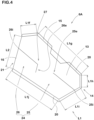
- FIG. 4 is a plan view of one of the laterally long blocks 6A.
- each of the laterally long blocks 6A and the vertically long blocks 6B in the present embodiment is provided with the chamfered portion 20 at 50% or more of the length L1 of the first block wall surface 15.
- Each of the laterally long blocks 6A and the vertically long blocks 6B is provided with the chamfered portion 20 preferably in the range of 85% or more of the length L1, and more specifically, it is even more preferred that the chamfered portion 20 is provided in the range of 100% of the length L1.
- each of the laterally long blocks 6A and the vertically long blocks 6B in the present embodiment has the second block wall surface 16 formed only by the wall surface main body 21 without the chamfered portion 20 formed thereon.
- the length L1 of the first block wall surface 15 of each of the laterally long blocks 6A is the sum of a length L1g, a length L1h, a length L1i, and a length L1j.
- the first block wall surface 15 and the second block wall surface 16 of each of the laterally long blocks 6A have a radial cross-sectional shape shown in FIGs. 3A and 3B respectively, for example.
- each of the laterally long blocks 6A is demarcated by the crown lateral grooves 10 adjacent to each other in the tire circumferential direction, one of the first shoulder circumferential grooves 3, and one of the first crown joint grooves 11A.
- Each of the vertically long blocks 6B is demarcated by the crown lateral grooves 10 adjacent to each other in the tire circumferential direction, one of the first shoulder circumferential grooves 3, and one of the second crown joint grooves 11B.
- each of the laterally long blocks 6A is provided with crown sipes 24.
- the crown sipes 24 include a first crown sipe 25 and a second crown sipe 26.
- the first crown sipe 25 has a first end (25i) connected with the first block wall surface 15 and a second end (25e) terminating within the ground contacting surface 13 to have a closed end.
- the term "closed end” means an end not connected with other sipes or grooves. The same applies hereinafter.
- the first crown sipe 25 extends linearly over the entire length thereof.
- the second crown sipe 26 has a first end (26i) connected with the second block wall surface 16 and a second end (26e) terminating within the ground contacting surface 13 to have a closed end.
- the second crown sipe 26 has a bent portion 27 bent at an obtuse angle between the first end and the second end. Thereby, the second crown sipe 26 is configured to have two linear portions connected at the bent portion 27.
- the laterally long blocks 6A configured as such exert a high edge effect and suppress a decrease in the block rigidity.
- a sipe refers to an incision having a width of less than 1.5 mm and is distinguished from a groove having a groove width of 1.5 mm or more.
- the crown blocks 5 include a plurality of second crown blocks 7 arranged axially inside the first crown blocks 6.
- Each of the second crown blocks 7 is arranged on the tire equator (C).
- FIG. 5 is a plan view of one of the second crown blocks 7.
- each of the second crown blocks 7 includes the ground contacting surface 13 and the block wall surface 14 extending radially inward from the ground contacting surface 13.
- the block wall surface 14 of each of the second crown blocks 7 is formed only by the first block wall surface 15 adjacent to one of the crown grooves 9.
- the block wall surface 14 of each of the second crown blocks 7 is provided with the chamfered portion 20 on the ground contacting surface 13 side in the range of 50% or more of a length L3 of the block wall surface 14 measured along the ground contacting surface 13.
- the second crown blocks 7 configured as such maintain the anti-wear performance even higher.
- the block wall surface 14 of each of the second crown blocks 7 has the chamfered portion 20 preferably in the range of 70% or more, and more preferably in the range of 85% or more of the length L3 of the block wall surface 14.
- the block wall surface 14 of each of the second crown blocks 7 has the chamfered portion 20 formed in the range of 100% of the length L3 of the block wall surface 14.
- the length L3 of the block wall surface 14 is represented by the total sum of linearly extending portions, similar to the length L1 of the first block wall surface 15.
- the length L1 is the sum of lengths (L3a) to (L3k) and a length (L3m).
- sipes disposed on the ground contacting surface 13 are omitted for convenience.
- the block wall surface 14 of each of the second crown blocks 7 includes the chamfered portion 20 and the wall surface main body 21 extending radially inward from the chamfered portion 20.
- the wall surface main body 21 includes the linear portion 22 and the arcuate portion 23, for example.
- the linear portions 22 of the second crown blocks 7 include first portions 22A and second portions 22B. Each of the first portion 22A is formed similarly to the linear portion 22 of the first block wall surface 15 (shown in Figure 3A ).
- FIG. 6 is a radial cross section of one of the second portions 22B and a C-C cross sectional view of FIG. 1 . As shown in FIG.
- each of the second portions 22B includes an outer portion (29a) connected to the chamfered portion 20, an inner portion (29b) connected to the arcuate portion 23, and a joint portion (29c) connecting the outer portion (29a) and the inner portion (29b).
- the joint portion (29c) is formed with a gentler slope having an angle with respect to the tire radial direction larger than the outer portion (29a) and the inner portion (29b), for example.
- the joint portion (29c) is formed parallel to the ground contacting surface 13 in the present embodiment.
- the first portions 22A are provided on the block wall surfaces 14 adjacent to the crown lateral grooves 10 and the block wall surfaces 14 adjacent to the second crown joint grooves 11B, for example.
- the second portions 22B are provided only in the block wall surfaces 14 adjacent to the crown lateral grooves 10, for example.
- a total area of the chamfered portions 20 is preferably 1% or more, more preferably 2% or more, and preferably 5% or less, and more preferably 4% or less of a total area of the ground contacting surfaces 13 of the crown blocks 5. Therefore, the anti-wear performance is maintained effectively.
- FIG. 7 is a plan view of the tread portion 2 outside the first shoulder circumferential groove 3 in the tire axial direction.
- the tread portion 2 includes a plurality of shoulder blocks 41 arranged axially outside each of the first shoulder circumferential grooves 3 and a plurality of shoulder grooves 42 separating the shoulder blocks 41 from each other.
- Each of the shoulder grooves 42 extends axially outward from one of the first shoulder circumferential grooves 3.
- Each of the shoulder blocks 41 includes a ground contacting surface 43 and a shoulder block wall surface 44 extending radially inward from the ground contacting surface 43.
- the shoulder block wall surface 44 includes third block wall surfaces 45 each adjacent to and facing a respective one of the shoulder grooves 42 and a fourth block wall surface 46 adjacent to and facing one of the first shoulder circumferential grooves 3.
- the third block wall surfaces 45 are not provided with a chamfered portion on the ground contacting surface 43 side, for example. Further, the fourth block wall surface 46 does not have a chamfered portion on the ground contacting surface 43 side in the present embodiment. As a result, the on-snow performance is further improved.
- the third block wall surfaces 45 and the fourth block wall surface 46 are each formed of the wall surface main body 21 including the linear portion 22 and the arcuate portion 23 (shown in FIG. 3B ) similar to the second block wall surface 16, for example.
- the third block wall surfaces 45 and the fourth block wall surface 46 are each formed only by the wall surface main body 21 in the present embodiment.
- the shoulder grooves 42 include shoulder lateral groove portions 42A arranged in the tire circumferential direction and each extending from one of the first shoulder circumferential groove 3 to one of the first tread edges T1 adjacent thereto and shoulder longitudinal groove portions 42B each connecting the shoulder lateral groove portions 42A adjacent to each other in the tire circumferential direction, for example.
- Each of the shoulder longitudinal groove portions 42B extends on one of the first tread edges T1, for example.
- the third block wall surfaces 45 include third lateral block wall surfaces 45A adjacent to the shoulder lateral groove portions 42A and third longitudinal block wall surfaces 45B facing the shoulder longitudinal groove portions 42B.
- the shoulder block wall surfaces 44 include cutout portions 48 recessed toward inside of the ground contacting surface 43. It should be noted that the cutout portion 48 is recessed toward the center of the ground contacting surface 43 and recessed radially inward from the ground contacting surface 43 in the present embodiment, for example.
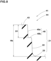
- FIG. 8 is a D-D cross sectional view of FIG. 7 . As shown in FIG. 8 , the cutout portion 48 is provided in the wall surface main body 21, for example.
- the wall surface main body 21 in the present embodiment includes the cutout portion 48, the linear portion 22, and the arcuate portion 23.
- Each of the cutout portions 48 includes a lateral facing surface (48a) extending radially inward from the ground contacting surface 43 and facing toward a groove center (groove center of the shoulder lateral groove portion 42A in this case) and an outward facing surface (48b) connected to the lateral facing surface (48a) and facing outward in the tire radial direction, for example.
- the cutout portions 48 configured as such increase the volume of snow to be sheared, therefore, the on-snow performance is further improved.
- the outward facing surface (48b) is connected to the linear portion 22, for example.
- the cutout portions 48 are provided in the third lateral block wall surfaces 45A, for example.
- the cutout portions 48 are provided one on each third lateral block wall surface 45A, for example.
- the cutout portions 48 are also provided in the fourth block wall surfaces 46, for example.
- the cutout portions 48 are not provided in the third longitudinal block wall surfaces 45B in the present embodiment.
- a total area of the cutout portions 48 is preferably 1% or more, more preferably 2% or more, and preferably 5% or less, and even more preferably 4% or less of a total area of the ground contacting surfaces 43 of the shoulder blocks 41. Since the total area of the cutout portions 48 is 1% or more of the total area of the ground contacting surfaces 43 of the shoulder blocks 41, the on-snow performance is improved when the external shapes of the shoulder blocks 41 are the same. Since the total area of the cutout portions 48 is 5% or less of the total area of the ground contacting surfaces 43 of the shoulder blocks 41, the anti-wear performance is maintained when the external shapes of the shoulder blocks 41 are the same.
- a depth D1 of each of the cutout portions 48 is preferably 10% or more, more preferably 20% or more, and preferably 50% or less, and even more preferably 40% or less of a height (Hb) in the tire radial direction of each of the shoulder blocks 41.
- the shoulder blocks 41 in the present embodiment include first shoulder blocks 41A and second shoulder blocks 41B each having an axial length smaller than each of the first shoulder blocks 41A.
- Each of the first shoulder blocks 41A is demarcated by a pair of the shoulder lateral groove portions 42A, one of the first tread edges T1, and one of the first shoulder circumferential grooves 3.
- Each of the second shoulder blocks 41B is demarcated by a pair of the shoulder lateral groove portions 42A, one of the shoulder longitudinal groove portions 42B, and one of the first shoulder circumferential grooves 3.
- Each of the second shoulder blocks 41B has an axially outer end (41e) located axially inside a respective one of the first tread edges T1.
- the shoulder blocks 41 of the present embodiment are provided with shoulder sipes 50.
- the shoulder sipes include first shoulder sipes 50A provided in the first shoulder blocks 41A and second shoulder sipes 50B provided in the second shoulder blocks 41B.
- Each of the first shoulder sipes 50A has an axially outer end (51a) terminating axially inside a respective one of the first tread edges T1 to have a closed end, for example.
- Each of the second shoulder sipes 50B has an axially outer end (51b) terminating to have a closed end within the ground contacting surface 43 without connecting to one of the shoulder longitudinal groove portions 42B, for example.
- FIG. 9 is a plan view of the tread portion 2 according to another embodiment.
- the same reference numerals are assigned to configurations same as those of the previously described embodiment, and the descriptions thereof are omitted.
- the second block wall surface 16 is provided with the chamfered portion 20 formed on the ground contacting surface 13 side in the range from 35% to 45% of the length L2 of the second block wall surface 16 measured along the ground contacting surface 13. Even in the tire 1 configured as such, the on-snow performance is further improved while the anti-wear performance is maintained.
- the present invention includes the following aspects.
- a tire including a tread portion wherein
- an angle ⁇ 1 of the chamfered portion with respect to a normal line of the ground contacting surface is 10 degrees or more and 30 degrees or less.
- a total area of the recessed portions of the shoulder block wall surfaces of the shoulder blocks is 1% or more and 5% or less of a total area of the ground contacting surfaces of the shoulder blocks in a tread plan view.
- a total area of the chamfered portions of the crown blocks is 1% or more and 5% or less of a total area of the ground contacting surfaces of the crown blocks in a tread plan view.
Landscapes
- Engineering & Computer Science (AREA)
- Mechanical Engineering (AREA)
- Tires In General (AREA)
Abstract
Description
- This application claims the benefit of foreign priority to Japanese Patent Applications No.
JP2022-060431, filed March 31, 2022 - The present invention relates to a tire.
-
Japanese Unexamined Patent Application Publication No. 2021-62655 - In recent years, there has been a demand for further improvement in on-snow performance while maintaining anti-wear performance for tires, especially tires for SUVs.
- The present invention was made in view of the above, and a primary object thereof is to provide a tire capable of further improving the on-snow performance while maintaining the anti-wear performance.
- The present invention is a tire including a tread portion wherein the tread portion includes a first tread edge, a first shoulder circumferential groove adjacent to the first tread edge and arranged between the first tread edge and a tire equator, a plurality of crown blocks arranged inside the first shoulder circumferential groove in a tire axial direction, and a plurality of crown grooves arranged axially inside the first shoulder circumferential groove to separate the crown blocks from each other,
- the crown blocks include a plurality of first crown blocks adjacent to the first shoulder circumferential groove,
- each of the first crown blocks includes a ground contacting surface and a block wall surface extending inward in a tire radial direction from the ground contacting surface,
- the block wall surface includes a first block wall surface adjacent to one of the crown grooves and a second block wall surface adjacent to the first shoulder circumferential groove,
- the first block wall surface is provided with a chamfered portion on the ground contacting surface side in a range of 50% or more of a length of the first block wall surface measured along the ground contacting surface, and
- the second block wall surface is either not provided with the chamfered portion on the ground contacting surface side or provided with the chamfered portion on the ground contacting surface side in a range of less than 50% of a length of the second block wall surface measured along the ground contacting surface.
- It is possible that the tire of the present invention further improves the on-snow performance while maintain the anti-wear performance by adopting the above-mentioned configuration.
-
-
FIG. 1 is a plan view of a tread portion according to an embodiment of the present invention. -
FIG. 2 is a plan view of one of first crown blocks ofFIG. 1 . -
FIG. 3A is an A-A cross sectional view ofFIG. 1 . -
FIG. 3B is a B-B cross sectional view ofFIG. 1 . -
FIG. 4 is a plan view of one of laterally long blocks. -
FIG. 5 is a plan view of one of second crown blocks ofFIG. 1 . -
FIG. 6 is a C-C cross sectional view ofFIG. 1 . -
FIG. 7 is a plan view of shoulder blocks. -
FIG. 8 is a D-D cross sectional view ofFIG. 7 . -
FIG. 9 is a plan view of the tread portion according to another embodiment. - An embodiment of the present invention will now be described below in conjunction with accompanying drawings.
-
FIG. 1 is a developed plan view of atread portion 2 of atire 1 of the present embodiment. The present invention is applied to pneumatic tires for SUVs suitable for running on rough terrain, for example. The present invention can also be applied to pneumatic tires for passenger cars and for heavy duty, and non-pneumatic tires configured not to be filled with compressed air. - As shown in
FIG. 1 , thetread portion 2 of the present embodiment includes a first tread edge T1, a first shouldercircumferential groove 3, a plurality of crown blocks 5 and a plurality ofcrown grooves 9. The first shouldercircumferential groove 3 is arranged between the first tread edge T1 and a tire equator (C) and adjacent to the first tread edge T1. The crown blocks 5 are arranged inside the first shouldercircumferential groove 3 in a tire axial direction. Thecrown grooves 9 are arranged axially inside the first shouldercircumferential groove 3 and demarcate the crown blocks 5. - The crown blocks include a plurality of
first crown blocks 6 adjacent immediately to the first shouldercircumferential groove 3. Each of thefirst crown blocks 6 includes aground contacting surface 13 and ablock wall surface 14 extending radially inward from theground contacting surface 13. - The
block wall surface 14 includes a firstblock wall surface 15 adjacent to (so as to face) one of thecrown grooves 9 and a secondblock wall surface 16 adjacent to (so as to face) the first shouldercircumferential groove 3. In other words, the secondblock wall surface 16 is arranged axially outside the firstblock wall surface 15. -
FIG. 2 is an enlarged view of one of thefirst crown blocks 6.FIG. 3A is an A-A cross-sectional view ofFIG. 1 andFIG. 3B is a B-B cross-sectional view ofFIG. 1 . As shown inFIGs. 2 ,3A, and 3B , the firstblock wall surface 15 is provided with a chamferedportion 20 extending 50% or more of a length L1 of the firstblock wall surface 15 measured along the ground contacting surface 13 (measured along the contour of theground contacting surface 13 in this case, the same applies hereinafter). In the present specification, the length L1 of the firstblock wall surface 15 is defined as the sum of the lengths of the linearly extending portions, and in the case of the first crown block shown inFIG. 2 , the length L1 is the sum of a length (L1a), a length (L1b), a length (L1c), a length (L1d), and a length (L1e). The firstblock wall surface 15 configured as such has great rigidity and thus enhances the basic anti-wear performance of the block. The secondblock wall surface 16 is not provided with the chamfered portion on theground contacting surface 13 side or provided with the chamferedportion 20 arranged on theground contacting surface 13 side and extending less than 50% of a length L2 (not shown) of the secondblock wall surface 16 measured along theground contacting surface 13. The length L2 of the secondblock wall surface 16 is also defined by the sum of the lengths of the linearly extending portions, and in the case of thefirst crown block 6 shown inFIG. 2 , the length L2 is the sum of a length (L2a), a length (L2b), a length (L2c), a length (L2d), a length (L2e), and a length (L2f). The secondblock wall surface 16 configured as such exerts a high edge effect on snowy roads and thus improves the on-snow performance. Further, since a relatively small ground contact pressure acts on the secondblock wall surface 16, wear is suppressed even if the chamferedportion 20 is not provided. Therefore, thetire 1 of the present embodiment can further improve the on-snow performance while maintaining the anti-wear performance. Furthermore, thetire 1 configured as such has excellent steering stability performance and excellent wet performance. The secondblock wall surface 16 of the present embodiment does not have a chamfered portion formed on theground contacting surface 13 side, therefore, it exerts high on-snow performance. - In order to improve the anti-wear performance, the first
block wall surface 15 is provided with the chamferedportion 20 in the range of 70% or more, more preferably in the range of 85% or more of the length L1 of the firstblock wall surface 15. In the present embodiment, the firstblock wall surface 15 has the chamferedportion 20 formed in the range of 100% of the length L1 of the firstblock wall surface 15. In a tread plan view, the firstblock wall surface 15 extends in a zigzag shape. - An angle θ1 of the
chamfered portion 20 with respect to a normal line (n1) of theground contacting surface 13 is preferably 10 degrees or more, more preferably 15 degrees or more, and preferably 30 degrees or less, and even more preferably 25 degrees or less. Since the angle θ1 of the chamferedportion 20 is 10 degrees or more, the anti-wear performance is maintained high. In addition, since drainage property is enhanced, the wet performance is improved. Since the angle θ1 of thechamfered portion 20 is 30 degrees or less, high on-snow performance is exerted. - The first
block wall surface 15 includes a wall surfacemain body 21 extending inward in the tire radial direction from the chamferedportion 20. The wall surfacemain body 21 in the present embodiment includes alinear portion 22 extending linearly in the tire radial direction over the entire length thereof, and anarcuate portion 23 extending in an arc shape to connect thelinear portion 22 and a groove bottom (9s) of one of thecrown grooves 9 adjacent thereto. It should be noted that the wall surfacemain body 21 is not limited to such an aspect, and for example, the wall surfacemain body 21 may include a large arcuate portion (not shown) having a larger radius of curvature than thearcuate portion 23 and connecting thearcuate portion 23 with the chamferedportion 20. - A difference (θ1-θ2) between the angle θ1 of the chamfered
portion 20 and an angle θ2 of the wall surfacemain body 21 with respect to the normal line (n1) is preferably 10 degrees or more, more preferably 15 degrees or more, and preferably 30 degrees or less, and more preferably 25 degrees or less. Since the difference (θ1-θ2) is 10 degrees or more, the rigidity of the first crown blocks 6 can be maintained high, thereby, the anti-wear performance is maintained. Since the difference (θ1-θ2) is 30 degrees or less, the wall surfacemain body 21 secures the shearing force on a snowy road surface, therefore, the on-snow performance is improved. The angle θ2 of the wall surfacemain body 21 is specified by the angle of thelinear portion 22. - A length H1 in the tire radial direction of the chamfered
portion 20 is preferably 20% or more, more preferably 25% or more, and preferably 40% or less, more preferably 35% or less of a length (Ha) in the tire radial direction of theblock wall surface 14. Since the length H1 of the chamferedportion 20 is 20% or more of the length (Ha) of theblock wall surface 14, the anti-wear performance is maintained. Since the length H1 of the chamferedportion 20 is 40% or less of the length (Ha) of theblock wall surface 14, the improving effect of the on-snow performance is ensured. - As shown in
FIG. 3B , the secondblock wall surface 16 in the present embodiment is formed by the wall surfacemain body 21, which includes thelinear portion 22 and thearcuate portion 23. The secondblock wall surface 16 is formed only by the wall surfacemain body 21 at 100% of the length L2 of the secondblock wall surface 16 measured along theground contacting surface 13, for example. - As shown in
FIG. 1 , thetread portion 2 of the present embodiment adopts a point-symmetrical pattern with an arbitrary point on the tire equator (C) as the center of symmetry. Thereby, thetread portion 2 of the present embodiment is provided with a pair of the first tread edges T1 and a pair of the first shouldercircumferential grooves 3. It should be noted that thetread portion 2 may be configured as a line-symmetrical pattern with the tire equator (C) as the axis of symmetry, for example. Further, thetread portion 2 is not limited to the point-symmetric pattern or the line-symmetric pattern. - The first tread edges T1 are defined as the outermost ground contact positions in the tire axial direction when the
tire 1 in a standard state is in contact with a flat surface with zero camber angle by being loaded with a standard tire load. A tread width TW is the distance in the tire axial direction between the first tread edges T1. - The term "standard state" refers to a state in which the
tire 1 is mounted on a standard rim (not shown), inflated to a standard inner pressure, and loaded with no tire load. Dimensions of various parts of thetire 1 are the values measured in this standard state Unless otherwise specified. - The term "standard rim" refers to a wheel rim specified for the concerned tire by a standard included in a standardization system on which the tire is based, for example, the "normal wheel rim" in JATMA, "Design Rim" in TRA, and "Measuring Rim" in ETRTO.
- The term "standard inner pressure" refers to air pressure specified for the concerned tire by a standard included in a standardization system on which the tire is based, for example, the maximum air pressure in JATMA, maximum value listed in the "TIRE LOAD LIMITS AT VARIOUS COLD INFLATION PRESSURES" table in TRA, and "INFLATION PRESSURE" in ETRTO.
- The term "standard tire load" refers to a tire load specified for the concerned tire by a standard included in a standardization system on which the tire is based, for example, the "maximum load capacity" in JATMA, maximum value listed in "TIRE LOAD LIMITS AT VARIOUS COLD INFLATION PRESSURES" table in TRA, and "LOAD CAPACITY" in ETRTO.
- In each of the first crown blocks 6, the first
block wall surface 15 has an outer end (15e) in the tire axial direction positioned at a distance (Lb) from the tire equator (C) in the tire axial direction and the distance (Lb) is in the range from 40% to 60% of the tread width TW. The outer end (15e) of the firstblock wall surface 15 is provided with the chamferedportion 20. Therefore, the anti-wear performance is maintained high. - The
crown grooves 9 include a plurality ofcrown lateral grooves 10 extending in the tire axial direction to connect between the first shouldercircumferential grooves 3, and a plurality of crownjoint grooves 11 each connecting a pair of thecrown lateral grooves 10 adjacent to each other in a tire circumferential direction. Each of thecrown lateral grooves 10 extends in a zigzag manner, for example. The crownjoint grooves 11 in the present embodiment include first crownjoint grooves 11A each extending linearly on the tire equator (C) and second crownjoint grooves 11B each shifted from the tire equator (C) in the tire axial direction and extending in an L-shape. - The first crown blocks 6 in the present embodiment include laterally
long blocks 6A each having a circumferential length smaller than an axial length thereof, and verticallylong blocks 6B each having a circumferential length larger than an axial length thereof. The laterallylong blocks 6A and the verticallylong blocks 6B are arranged alternately in the tire circumferential direction, for example. Thefirst crown block 6 shown inFIG. 2 is the verticallylong block 6B. -
FIG. 4 is a plan view of one of the laterallylong blocks 6A. As shown inFIGs. 2 and4 , each of the laterallylong blocks 6A and the verticallylong blocks 6B in the present embodiment is provided with the chamferedportion 20 at 50% or more of the length L1 of the firstblock wall surface 15. Each of the laterallylong blocks 6A and the verticallylong blocks 6B is provided with the chamferedportion 20 preferably in the range of 85% or more of the length L1, and more specifically, it is even more preferred that the chamferedportion 20 is provided in the range of 100% of the length L1. Further, each of the laterallylong blocks 6A and the verticallylong blocks 6B in the present embodiment has the secondblock wall surface 16 formed only by the wall surfacemain body 21 without the chamferedportion 20 formed thereon. As shown inFIG. 4 , the length L1 of the firstblock wall surface 15 of each of the laterallylong blocks 6A is the sum of a length L1g, a length L1h, a length L1i, and a length L1j. The firstblock wall surface 15 and the secondblock wall surface 16 of each of the laterallylong blocks 6A have a radial cross-sectional shape shown inFIGs. 3A and 3B respectively, for example. - As shown in
FIG. 1 , each of the laterallylong blocks 6A is demarcated by thecrown lateral grooves 10 adjacent to each other in the tire circumferential direction, one of the first shouldercircumferential grooves 3, and one of the first crownjoint grooves 11A. Each of the verticallylong blocks 6B is demarcated by thecrown lateral grooves 10 adjacent to each other in the tire circumferential direction, one of the first shouldercircumferential grooves 3, and one of the second crownjoint grooves 11B. - As shown in
FIG. 4 , each of the laterallylong blocks 6A is provided withcrown sipes 24. The crown sipes 24 include afirst crown sipe 25 and asecond crown sipe 26. Thefirst crown sipe 25 has a first end (25i) connected with the firstblock wall surface 15 and a second end (25e) terminating within theground contacting surface 13 to have a closed end. The term "closed end" means an end not connected with other sipes or grooves. The same applies hereinafter. Thefirst crown sipe 25 extends linearly over the entire length thereof. Thesecond crown sipe 26 has a first end (26i) connected with the secondblock wall surface 16 and a second end (26e) terminating within theground contacting surface 13 to have a closed end. Thesecond crown sipe 26 has abent portion 27 bent at an obtuse angle between the first end and the second end. Thereby, thesecond crown sipe 26 is configured to have two linear portions connected at thebent portion 27. The laterallylong blocks 6A configured as such exert a high edge effect and suppress a decrease in the block rigidity. In the present specification, a sipe refers to an incision having a width of less than 1.5 mm and is distinguished from a groove having a groove width of 1.5 mm or more. - As shown in
FIG. 1 , the crown blocks 5 include a plurality of second crown blocks 7 arranged axially inside the first crown blocks 6. Each of the second crown blocks 7 is arranged on the tire equator (C). -
FIG. 5 is a plan view of one of the second crown blocks 7. As shown inFIG. 5 , each of the second crown blocks 7 includes theground contacting surface 13 and theblock wall surface 14 extending radially inward from theground contacting surface 13. Theblock wall surface 14 of each of the second crown blocks 7 is formed only by the firstblock wall surface 15 adjacent to one of thecrown grooves 9. Theblock wall surface 14 of each of the second crown blocks 7 is provided with the chamferedportion 20 on theground contacting surface 13 side in the range of 50% or more of a length L3 of theblock wall surface 14 measured along theground contacting surface 13. The second crown blocks 7 configured as such maintain the anti-wear performance even higher. Theblock wall surface 14 of each of the second crown blocks 7 has the chamferedportion 20 preferably in the range of 70% or more, and more preferably in the range of 85% or more of the length L3 of theblock wall surface 14. In the present embodiment, theblock wall surface 14 of each of the second crown blocks 7 has the chamferedportion 20 formed in the range of 100% of the length L3 of theblock wall surface 14. In each of the second crown blocks 7, the length L3 of theblock wall surface 14 is represented by the total sum of linearly extending portions, similar to the length L1 of the firstblock wall surface 15. In the case of the present embodiment, the length L1 is the sum of lengths (L3a) to (L3k) and a length (L3m). InFIG. 5 , sipes disposed on theground contacting surface 13 are omitted for convenience. - The
block wall surface 14 of each of the second crown blocks 7 includes the chamferedportion 20 and the wall surfacemain body 21 extending radially inward from the chamferedportion 20. The wall surfacemain body 21 includes thelinear portion 22 and thearcuate portion 23, for example. Thelinear portions 22 of the second crown blocks 7 includefirst portions 22A andsecond portions 22B. Each of thefirst portion 22A is formed similarly to thelinear portion 22 of the first block wall surface 15 (shown inFigure 3A ).FIG. 6 is a radial cross section of one of thesecond portions 22B and a C-C cross sectional view ofFIG. 1 . As shown inFIG. 6 , each of thesecond portions 22B includes an outer portion (29a) connected to the chamferedportion 20, an inner portion (29b) connected to thearcuate portion 23, and a joint portion (29c) connecting the outer portion (29a) and the inner portion (29b). The joint portion (29c) is formed with a gentler slope having an angle with respect to the tire radial direction larger than the outer portion (29a) and the inner portion (29b), for example. The joint portion (29c) is formed parallel to theground contacting surface 13 in the present embodiment. - The
first portions 22A are provided on the block wall surfaces 14 adjacent to thecrown lateral grooves 10 and the block wall surfaces 14 adjacent to the second crownjoint grooves 11B, for example. Thesecond portions 22B are provided only in the block wall surfaces 14 adjacent to thecrown lateral grooves 10, for example. - In the tread plan view, a total area of the chamfered
portions 20 is preferably 1% or more, more preferably 2% or more, and preferably 5% or less, and more preferably 4% or less of a total area of theground contacting surfaces 13 of the crown blocks 5. Therefore, the anti-wear performance is maintained effectively. -
FIG. 7 is a plan view of thetread portion 2 outside the first shouldercircumferential groove 3 in the tire axial direction. As shown inFIG. 7 , thetread portion 2 includes a plurality ofshoulder blocks 41 arranged axially outside each of the first shouldercircumferential grooves 3 and a plurality ofshoulder grooves 42 separating the shoulder blocks 41 from each other. Each of theshoulder grooves 42 extends axially outward from one of the first shouldercircumferential grooves 3. - Each of the shoulder blocks 41 includes a
ground contacting surface 43 and a shoulderblock wall surface 44 extending radially inward from theground contacting surface 43. The shoulderblock wall surface 44 includes third block wall surfaces 45 each adjacent to and facing a respective one of theshoulder grooves 42 and a fourthblock wall surface 46 adjacent to and facing one of the first shouldercircumferential grooves 3. - The third block wall surfaces 45 are not provided with a chamfered portion on the
ground contacting surface 43 side, for example. Further, the fourthblock wall surface 46 does not have a chamfered portion on theground contacting surface 43 side in the present embodiment. As a result, the on-snow performance is further improved. The third block wall surfaces 45 and the fourthblock wall surface 46 are each formed of the wall surfacemain body 21 including thelinear portion 22 and the arcuate portion 23 (shown inFIG. 3B ) similar to the secondblock wall surface 16, for example. The third block wall surfaces 45 and the fourthblock wall surface 46 are each formed only by the wall surfacemain body 21 in the present embodiment. - The
shoulder grooves 42 include shoulderlateral groove portions 42A arranged in the tire circumferential direction and each extending from one of the first shouldercircumferential groove 3 to one of the first tread edges T1 adjacent thereto and shoulderlongitudinal groove portions 42B each connecting the shoulderlateral groove portions 42A adjacent to each other in the tire circumferential direction, for example. Each of the shoulderlongitudinal groove portions 42B extends on one of the first tread edges T1, for example. - The third block wall surfaces 45 include third lateral block wall surfaces 45A adjacent to the shoulder
lateral groove portions 42A and third longitudinal block wall surfaces 45B facing the shoulderlongitudinal groove portions 42B. - The shoulder block wall surfaces 44 include
cutout portions 48 recessed toward inside of theground contacting surface 43. It should be noted that thecutout portion 48 is recessed toward the center of theground contacting surface 43 and recessed radially inward from theground contacting surface 43 in the present embodiment, for example.FIG. 8 is a D-D cross sectional view ofFIG. 7 . As shown inFIG. 8 , thecutout portion 48 is provided in the wall surfacemain body 21, for example. The wall surfacemain body 21 in the present embodiment includes thecutout portion 48, thelinear portion 22, and thearcuate portion 23. Each of thecutout portions 48 includes a lateral facing surface (48a) extending radially inward from theground contacting surface 43 and facing toward a groove center (groove center of the shoulderlateral groove portion 42A in this case) and an outward facing surface (48b) connected to the lateral facing surface (48a) and facing outward in the tire radial direction, for example. Thecutout portions 48 configured as such increase the volume of snow to be sheared, therefore, the on-snow performance is further improved. The outward facing surface (48b) is connected to thelinear portion 22, for example. - The
cutout portions 48 are provided in the third lateral block wall surfaces 45A, for example. Thecutout portions 48 are provided one on each third lateralblock wall surface 45A, for example. Thecutout portions 48 are also provided in the fourth block wall surfaces 46, for example. Thecutout portions 48 are not provided in the third longitudinal block wall surfaces 45B in the present embodiment. - In the tread plan view, a total area of the
cutout portions 48 is preferably 1% or more, more preferably 2% or more, and preferably 5% or less, and even more preferably 4% or less of a total area of theground contacting surfaces 43 of the shoulder blocks 41. Since the total area of thecutout portions 48 is 1% or more of the total area of theground contacting surfaces 43 of the shoulder blocks 41, the on-snow performance is improved when the external shapes of the shoulder blocks 41 are the same. Since the total area of thecutout portions 48 is 5% or less of the total area of theground contacting surfaces 43 of the shoulder blocks 41, the anti-wear performance is maintained when the external shapes of the shoulder blocks 41 are the same. - A depth D1 of each of the
cutout portions 48 is preferably 10% or more, more preferably 20% or more, and preferably 50% or less, and even more preferably 40% or less of a height (Hb) in the tire radial direction of each of the shoulder blocks 41. As a result, the on-snow performance is further improved while the anti-wear performance is maintained. - The shoulder blocks 41 in the present embodiment include
first shoulder blocks 41A andsecond shoulder blocks 41B each having an axial length smaller than each of thefirst shoulder blocks 41A. Each of thefirst shoulder blocks 41A is demarcated by a pair of the shoulderlateral groove portions 42A, one of the first tread edges T1, and one of the first shouldercircumferential grooves 3. Each of thesecond shoulder blocks 41B is demarcated by a pair of the shoulderlateral groove portions 42A, one of the shoulderlongitudinal groove portions 42B, and one of the first shouldercircumferential grooves 3. Each of thesecond shoulder blocks 41B has an axially outer end (41e) located axially inside a respective one of the first tread edges T1. - The shoulder blocks 41 of the present embodiment are provided with
shoulder sipes 50. The shoulder sipes includefirst shoulder sipes 50A provided in thefirst shoulder blocks 41A andsecond shoulder sipes 50B provided in the second shoulder blocks 41B. Each of thefirst shoulder sipes 50A has an axially outer end (51a) terminating axially inside a respective one of the first tread edges T1 to have a closed end, for example. Each of thesecond shoulder sipes 50B has an axially outer end (51b) terminating to have a closed end within theground contacting surface 43 without connecting to one of the shoulderlongitudinal groove portions 42B, for example. -
FIG. 9 is a plan view of thetread portion 2 according to another embodiment. The same reference numerals are assigned to configurations same as those of the previously described embodiment, and the descriptions thereof are omitted. As shown inFIG. 9 , in each of the crown blocks in thetread portion 2 of this embodiment, the secondblock wall surface 16 is provided with the chamferedportion 20 formed on theground contacting surface 13 side in the range from 35% to 45% of the length L2 of the secondblock wall surface 16 measured along theground contacting surface 13. Even in thetire 1 configured as such, the on-snow performance is further improved while the anti-wear performance is maintained. - While detailed description has been made of an especially preferred embodiment of the present invention, the present invention can be embodied in various forms without being limited to the illustrated embodiment.
- The present invention includes the following aspects.
- A tire including a tread portion wherein
- the tread portion includes
- a first tread edge,
- a first shoulder circumferential groove adjacent to the first tread edge and arranged between the first tread edge and a tire equator,
- a plurality of crown blocks arranged inside the first shoulder circumferential groove in a tire axial direction, and
- a plurality of crown grooves arranged axially inside the first shoulder circumferential groove to separate the crown blocks from each other,
- the crown blocks include a plurality of first crown blocks adjacent to the first shoulder circumferential groove,
- each of the first crown blocks includes a ground contacting surface and a block wall surface extending inward in a tire radial direction from the ground contacting surface,
- the block wall surface includes a first block wall surface adjacent to one of the crown grooves and a second block wall surface adjacent to the first shoulder circumferential groove,
- the first block wall surface is provided with a chamfered portion on the ground contacting surface side in a range of 50% or more of a length of the first block wall surface measured along the ground contacting surface, and
- the second block wall surface is either not provided with the chamfered portion on the ground contacting surface side or provided with the chamfered portion on the ground contacting surface side in a range of less than 50% of a length of the second block wall surface measured along the ground contacting surface.
- The tire according to
Present Invention 1, wherein the first block wall surface is provided with the chamfered portion in the range of 100% of the length of the first block wall surface. - The tire according to
Present Invention - the first block wall surface includes a wall surface main body extending radially inward from the chamfered portion, and
- a difference (θ1-θ2) between an angle θ1 of the chamfered portion with respect to a normal line of the ground contacting surface and an angle θ2 of the wall surface main body with respect to the normal line is 10 degrees or more and 30 degrees or less.
- The tire according to any one of
Present Inventions 1 to 3, wherein the chamfered portion has a length in the tire radial direction of 20% or more and 40% or less of a length in the tire radial direction of the block wall surface. - The tire according to any one of
Present Inventions 1 to 4, wherein an angle θ1 of the chamfered portion with respect to a normal line of the ground contacting surface is 10 degrees or more and 30 degrees or less. - The tire according to any one of
Present Inventions 1 to 5, wherein - the tread portion further includes a plurality of shoulder blocks arranged axially outside the first shoulder circumferential groove and a plurality of shoulder grooves extending axially outward from the first shoulder circumferential groove to separate the shoulder blocks from each other,
- each of the shoulder blocks includes a ground contacting surface and a shoulder block wall surface extending radially inward from the ground contacting surface,
- the shoulder block wall surface includes a third block wall surface adjacent to one of the shoulder grooves and a fourth block wall surface adjacent to the first shoulder circumferential groove, and
- the third block wall surface is not provided with the chamfered portion on the ground contacting surface side.
- The tire according to
Present Invention 6, wherein the fourth block wall surface is not provided with the chamfered portion on the ground contacting surface side. - The tire according to
Present Invention - the shoulder block wall surface includes a cutout portion recessed toward inside of the ground contacting surface, and
- the cutout portion has a depth in the tire radial direction of 10% or more and 50% or less of a height in the tire radial direction of the each of the shoulder blocks.
- The tire according to Present Invention 8, wherein a total area of the recessed portions of the shoulder block wall surfaces of the shoulder blocks is 1% or more and 5% or less of a total area of the ground contacting surfaces of the shoulder blocks in a tread plan view.
- The tire according to any one of
Present Inventions 1 to 9, wherein - the crown blocks include a plurality of second crown blocks arranged axially inside the first crown blocks,
- each of the second crown blocks includes a ground contacting surface and a block wall surface extending radially inward from the ground contacting surface, and
- in each of the second crown blocks, the block wall surface is provided with a chamfered portion on the ground contacting surface side in a range of 50% or more of a length of the block wall surface measured along the ground contacting surface.
- The tire according to
Present Invention 10, wherein a total area of the chamfered portions of the crown blocks is 1% or more and 5% or less of a total area of the ground contacting surfaces of the crown blocks in a tread plan view. -
- 1
- tire
- 3
- first shoulder circumferential groove
- 6
- first crown block
- 9
- crown groove
- 13
- ground contacting surface
- 14
- block wall surface
- 15
- first block wall surface
- 16
- second block wall surface
- 20
- chamfered portion
- L1
- length of first block wall surface
- L2
- length of second block wall surface
Claims (11)
- A tire comprising a tread portion whereinthe tread portion includesa first tread edge,a first shoulder circumferential groove adjacent to the first tread edge and arranged between the first tread edge and a tire equator,a plurality of crown blocks arranged inside the first shoulder circumferential groove in a tire axial direction, anda plurality of crown grooves arranged axially inside the first shoulder circumferential groove to separate the crown blocks from each other,the crown blocks include a plurality of first crown blocks adjacent to the first shoulder circumferential groove,each of the first crown blocks includes a ground contacting surface and a block wall surface extending inward in a tire radial direction from the ground contacting surface,the block wall surface includes a first block wall surface adjacent to one of the crown grooves and a second block wall surface adjacent to the first shoulder circumferential groove,the first block wall surface is provided with a chamfered portion on the ground contacting surface side in a range of 50% or more of a length of the first block wall surface measured along the ground contacting surface, andthe second block wall surface is either not provided with the chamfered portion on the ground contacting surface side or provided with the chamfered portion on the ground contacting surface side in a range of less than 50% of a length of the second block wall surface measured along the ground contacting surface.
- The tire according to claim 1, wherein the first block wall surface is provided with the chamfered portion in the range of 100% of the length of the first block wall surface.
- The tire according to claim 1 or 2, whereinthe first block wall surface includes a wall surface main body extending radially inward from the chamfered portion, anda difference (θ1-θ2) between an angle θ1 of the chamfered portion with respect to a normal line of the ground contacting surface and an angle θ2 of the wall surface main body with respect to the normal line is 10 degrees or more and 30 degrees or less.
- The tire according to any one of claims 1 to 3, wherein the chamfered portion has a length in the tire radial direction of 20% or more and 40% or less of a length in the tire radial direction of the block wall surface.
- The tire according to any one of claims 1 to 4, wherein an angle θ1 of the chamfered portion with respect to a normal line of the ground contacting surface is 10 degrees or more and 30 degrees or less.
- The tire according to any one of claims 1 to 5, whereinthe tread portion further includes a plurality of shoulder blocks arranged axially outside the first shoulder circumferential groove and a plurality of shoulder grooves extending axially outward from the first shoulder circumferential groove to separate the shoulder blocks from each other,each of the shoulder blocks includes a ground contacting surface and a shoulder block wall surface extending radially inward from the ground contacting surface,the shoulder block wall surface includes a third block wall surface adjacent to one of the shoulder grooves and a fourth block wall surface adjacent to the first shoulder circumferential groove, andthe third block wall surface is not provided with the chamfered portion on the ground contacting surface side.
- The tire according to claim 6, wherein the fourth block wall surface is not provided with the chamfered portion on the ground contacting surface side.
- The tire according to claim 6 or 7, whereinthe shoulder block wall surface includes a cutout portion recessed toward inside of the ground contacting surface, andthe cutout portion has a depth in the tire radial direction of 10% or more and 50% or less of a height in the tire radial direction of the each of the shoulder blocks.
- The tire according to claim 8, wherein a total area of the recessed portions of the shoulder block wall surfaces of the shoulder blocks is 1% or more and 5% or less of a total area of the ground contacting surfaces of the shoulder blocks in a tread plan view.
- The tire according to any one of claims 1 to 9, whereinthe crown blocks include a plurality of second crown blocks arranged axially inside the first crown blocks,each of the second crown blocks includes a ground contacting surface and a block wall surface extending radially inward from the ground contacting surface, andin each of the second crown blocks, the block wall surface is provided with a chamfered portion on the ground contacting surface side in a range of 50% or more of a length of the block wall surface measured along the ground contacting surface.
- The tire according to claim 10, wherein a total area of the chamfered portions of the crown blocks is 1% or more and 5% or less of a total area of the ground contacting surfaces of the crown blocks in a tread plan view.
Applications Claiming Priority (1)
| Application Number | Priority Date | Filing Date | Title |
|---|---|---|---|
| JP2022060431A JP7859141B2 (en) | 2022-03-31 | tire |
Publications (2)
| Publication Number | Publication Date |
|---|---|
| EP4253092A1 true EP4253092A1 (en) | 2023-10-04 |
| EP4253092B1 EP4253092B1 (en) | 2025-05-07 |
Family
ID=85724557
Family Applications (1)
| Application Number | Title | Priority Date | Filing Date |
|---|---|---|---|
| EP23163035.1A Active EP4253092B1 (en) | 2022-03-31 | 2023-03-21 | Tire |
Country Status (3)
| Country | Link |
|---|---|
| US (1) | US20230311575A1 (en) |
| EP (1) | EP4253092B1 (en) |
| CN (1) | CN116890576A (en) |
Families Citing this family (4)
| Publication number | Priority date | Publication date | Assignee | Title |
|---|---|---|---|---|
| JP1780918S (en) * | 2023-10-06 | 2024-09-27 | Car Tires | |
| USD1109677S1 (en) * | 2024-06-21 | 2026-01-20 | Sailun Group Co., Ltd. | Tire |
| USD1109678S1 (en) * | 2024-08-05 | 2026-01-20 | Sailun Group Co., Ltd. | Tire |
| CN119749114A (en) * | 2025-01-10 | 2025-04-04 | 山东玲珑轮胎股份有限公司 | All-terrain tire suitable for all seasons |
Citations (6)
| Publication number | Priority date | Publication date | Assignee | Title |
|---|---|---|---|---|
| EP3015287A2 (en) * | 2014-10-31 | 2016-05-04 | Sumitomo Rubber Industries Limited | Pneumatic tire |
| EP3505369A1 (en) * | 2017-12-28 | 2019-07-03 | Sumitomo Rubber Industries, Ltd. | Tire |
| US20190255889A1 (en) * | 2018-02-21 | 2019-08-22 | Toyo Tire Corporation | Pneumatic tire |
| US20200156416A1 (en) * | 2018-11-20 | 2020-05-21 | Sumitomo Rubber Industries, Ltd. | Tire |
| JP2021062655A (en) | 2019-10-10 | 2021-04-22 | 住友ゴム工業株式会社 | tire |
| JP2022060431A (en) | 2017-03-09 | 2022-04-14 | 東芝テック株式会社 | Liquid discharge head and liquid discharge device |
-
2023
- 2023-02-02 US US18/104,860 patent/US20230311575A1/en not_active Abandoned
- 2023-02-28 CN CN202310213255.5A patent/CN116890576A/en active Pending
- 2023-03-21 EP EP23163035.1A patent/EP4253092B1/en active Active
Patent Citations (6)
| Publication number | Priority date | Publication date | Assignee | Title |
|---|---|---|---|---|
| EP3015287A2 (en) * | 2014-10-31 | 2016-05-04 | Sumitomo Rubber Industries Limited | Pneumatic tire |
| JP2022060431A (en) | 2017-03-09 | 2022-04-14 | 東芝テック株式会社 | Liquid discharge head and liquid discharge device |
| EP3505369A1 (en) * | 2017-12-28 | 2019-07-03 | Sumitomo Rubber Industries, Ltd. | Tire |
| US20190255889A1 (en) * | 2018-02-21 | 2019-08-22 | Toyo Tire Corporation | Pneumatic tire |
| US20200156416A1 (en) * | 2018-11-20 | 2020-05-21 | Sumitomo Rubber Industries, Ltd. | Tire |
| JP2021062655A (en) | 2019-10-10 | 2021-04-22 | 住友ゴム工業株式会社 | tire |
Also Published As
| Publication number | Publication date |
|---|---|
| CN116890576A (en) | 2023-10-17 |
| US20230311575A1 (en) | 2023-10-05 |
| JP2023151037A (en) | 2023-10-16 |
| EP4253092B1 (en) | 2025-05-07 |
Similar Documents
| Publication | Publication Date | Title |
|---|---|---|
| EP4253092B1 (en) | Tire | |
| EP2261064B1 (en) | Pneumatic tire | |
| EP3388257A1 (en) | Tire | |
| KR102460204B1 (en) | Tire | |
| CN108790615B (en) | Tyre for vehicle wheels | |
| CN108569086B (en) | Tyre for vehicle wheels | |
| KR20180001438A (en) | Tire | |
| JP2018140745A (en) | tire | |
| US11453243B2 (en) | Tire | |
| JP7095371B2 (en) | tire | |
| EP3354484B1 (en) | Tire | |
| EP4230439A1 (en) | Pneumatic tire | |
| CN112009178B (en) | Tire with a tire body | |
| US12594790B2 (en) | Tire | |
| US11135877B2 (en) | Tire | |
| EP4043245B1 (en) | Tyre | |
| CN114379287A (en) | Tyre for vehicle wheels | |
| EP3552846A1 (en) | Tyre | |
| JP7859141B2 (en) | tire | |
| US11648804B2 (en) | Tire | |
| EP4497612A1 (en) | Tire | |
| EP4234276A1 (en) | Tyre | |
| US20250319726A1 (en) | Tire | |
| EP4234274A1 (en) | Tyre | |
| EP4400334A1 (en) | Tire |
Legal Events
| Date | Code | Title | Description |
|---|---|---|---|
| PUAI | Public reference made under article 153(3) epc to a published international application that has entered the european phase |
Free format text: ORIGINAL CODE: 0009012 |
|
| STAA | Information on the status of an ep patent application or granted ep patent |
Free format text: STATUS: THE APPLICATION HAS BEEN PUBLISHED |
|
| AK | Designated contracting states |
Kind code of ref document: A1 Designated state(s): AL AT BE BG CH CY CZ DE DK EE ES FI FR GB GR HR HU IE IS IT LI LT LU LV MC ME MK MT NL NO PL PT RO RS SE SI SK SM TR |
|
| STAA | Information on the status of an ep patent application or granted ep patent |
Free format text: STATUS: REQUEST FOR EXAMINATION WAS MADE |
|
| 17P | Request for examination filed |
Effective date: 20231220 |
|
| RBV | Designated contracting states (corrected) |
Designated state(s): AL AT BE BG CH CY CZ DE DK EE ES FI FR GB GR HR HU IE IS IT LI LT LU LV MC ME MK MT NL NO PL PT RO RS SE SI SK SM TR |
|
| P01 | Opt-out of the competence of the unified patent court (upc) registered |
Effective date: 20240327 |
|
| GRAP | Despatch of communication of intention to grant a patent |
Free format text: ORIGINAL CODE: EPIDOSNIGR1 |
|
| STAA | Information on the status of an ep patent application or granted ep patent |
Free format text: STATUS: GRANT OF PATENT IS INTENDED |
|
| GRAS | Grant fee paid |
Free format text: ORIGINAL CODE: EPIDOSNIGR3 |
|
| INTG | Intention to grant announced |
Effective date: 20250116 |
|
| GRAA | (expected) grant |
Free format text: ORIGINAL CODE: 0009210 |
|
| STAA | Information on the status of an ep patent application or granted ep patent |
Free format text: STATUS: THE PATENT HAS BEEN GRANTED |
|
| AK | Designated contracting states |
Kind code of ref document: B1 Designated state(s): AL AT BE BG CH CY CZ DE DK EE ES FI FR GB GR HR HU IE IS IT LI LT LU LV MC ME MK MT NL NO PL PT RO RS SE SI SK SM TR |
|
| REG | Reference to a national code |
Ref country code: GB Ref legal event code: FG4D |
|
| REG | Reference to a national code |
Ref country code: CH Ref legal event code: EP |
|
| REG | Reference to a national code |
Ref country code: DE Ref legal event code: R096 Ref document number: 602023003278 Country of ref document: DE |
|
| REG | Reference to a national code |
Ref country code: IE Ref legal event code: FG4D |
|
| REG | Reference to a national code |
Ref country code: NL Ref legal event code: MP Effective date: 20250507 |
|
| PG25 | Lapsed in a contracting state [announced via postgrant information from national office to epo] |
Ref country code: FI Free format text: LAPSE BECAUSE OF FAILURE TO SUBMIT A TRANSLATION OF THE DESCRIPTION OR TO PAY THE FEE WITHIN THE PRESCRIBED TIME-LIMIT Effective date: 20250507 Ref country code: ES Free format text: LAPSE BECAUSE OF FAILURE TO SUBMIT A TRANSLATION OF THE DESCRIPTION OR TO PAY THE FEE WITHIN THE PRESCRIBED TIME-LIMIT Effective date: 20250507 Ref country code: PT Free format text: LAPSE BECAUSE OF FAILURE TO SUBMIT A TRANSLATION OF THE DESCRIPTION OR TO PAY THE FEE WITHIN THE PRESCRIBED TIME-LIMIT Effective date: 20250908 |
|
| REG | Reference to a national code |
Ref country code: LT Ref legal event code: MG9D |
|
| PG25 | Lapsed in a contracting state [announced via postgrant information from national office to epo] |
Ref country code: GR Free format text: LAPSE BECAUSE OF FAILURE TO SUBMIT A TRANSLATION OF THE DESCRIPTION OR TO PAY THE FEE WITHIN THE PRESCRIBED TIME-LIMIT Effective date: 20250808 Ref country code: NO Free format text: LAPSE BECAUSE OF FAILURE TO SUBMIT A TRANSLATION OF THE DESCRIPTION OR TO PAY THE FEE WITHIN THE PRESCRIBED TIME-LIMIT Effective date: 20250807 |
|
| PG25 | Lapsed in a contracting state [announced via postgrant information from national office to epo] |
Ref country code: NL Free format text: LAPSE BECAUSE OF FAILURE TO SUBMIT A TRANSLATION OF THE DESCRIPTION OR TO PAY THE FEE WITHIN THE PRESCRIBED TIME-LIMIT Effective date: 20250507 Ref country code: PL Free format text: LAPSE BECAUSE OF FAILURE TO SUBMIT A TRANSLATION OF THE DESCRIPTION OR TO PAY THE FEE WITHIN THE PRESCRIBED TIME-LIMIT Effective date: 20250507 |
|
| REG | Reference to a national code |
Ref country code: AT Ref legal event code: MK05 Ref document number: 1792096 Country of ref document: AT Kind code of ref document: T Effective date: 20250507 |
|
| PG25 | Lapsed in a contracting state [announced via postgrant information from national office to epo] |
Ref country code: BG Free format text: LAPSE BECAUSE OF FAILURE TO SUBMIT A TRANSLATION OF THE DESCRIPTION OR TO PAY THE FEE WITHIN THE PRESCRIBED TIME-LIMIT Effective date: 20250507 |
|
| PG25 | Lapsed in a contracting state [announced via postgrant information from national office to epo] |
Ref country code: HR Free format text: LAPSE BECAUSE OF FAILURE TO SUBMIT A TRANSLATION OF THE DESCRIPTION OR TO PAY THE FEE WITHIN THE PRESCRIBED TIME-LIMIT Effective date: 20250507 |
|
| PG25 | Lapsed in a contracting state [announced via postgrant information from national office to epo] |
Ref country code: AT Free format text: LAPSE BECAUSE OF FAILURE TO SUBMIT A TRANSLATION OF THE DESCRIPTION OR TO PAY THE FEE WITHIN THE PRESCRIBED TIME-LIMIT Effective date: 20250507 |
|
| PG25 | Lapsed in a contracting state [announced via postgrant information from national office to epo] |
Ref country code: RS Free format text: LAPSE BECAUSE OF FAILURE TO SUBMIT A TRANSLATION OF THE DESCRIPTION OR TO PAY THE FEE WITHIN THE PRESCRIBED TIME-LIMIT Effective date: 20250807 |
|
| PG25 | Lapsed in a contracting state [announced via postgrant information from national office to epo] |
Ref country code: IS Free format text: LAPSE BECAUSE OF FAILURE TO SUBMIT A TRANSLATION OF THE DESCRIPTION OR TO PAY THE FEE WITHIN THE PRESCRIBED TIME-LIMIT Effective date: 20250907 |
|
| PG25 | Lapsed in a contracting state [announced via postgrant information from national office to epo] |
Ref country code: LV Free format text: LAPSE BECAUSE OF FAILURE TO SUBMIT A TRANSLATION OF THE DESCRIPTION OR TO PAY THE FEE WITHIN THE PRESCRIBED TIME-LIMIT Effective date: 20250507 |
|
| PG25 | Lapsed in a contracting state [announced via postgrant information from national office to epo] |
Ref country code: DK Free format text: LAPSE BECAUSE OF FAILURE TO SUBMIT A TRANSLATION OF THE DESCRIPTION OR TO PAY THE FEE WITHIN THE PRESCRIBED TIME-LIMIT Effective date: 20250507 Ref country code: SM Free format text: LAPSE BECAUSE OF FAILURE TO SUBMIT A TRANSLATION OF THE DESCRIPTION OR TO PAY THE FEE WITHIN THE PRESCRIBED TIME-LIMIT Effective date: 20250507 |
|
| PG25 | Lapsed in a contracting state [announced via postgrant information from national office to epo] |
Ref country code: CZ Free format text: LAPSE BECAUSE OF FAILURE TO SUBMIT A TRANSLATION OF THE DESCRIPTION OR TO PAY THE FEE WITHIN THE PRESCRIBED TIME-LIMIT Effective date: 20250507 |
|
| PG25 | Lapsed in a contracting state [announced via postgrant information from national office to epo] |
Ref country code: EE Free format text: LAPSE BECAUSE OF FAILURE TO SUBMIT A TRANSLATION OF THE DESCRIPTION OR TO PAY THE FEE WITHIN THE PRESCRIBED TIME-LIMIT Effective date: 20250507 |
|
| PG25 | Lapsed in a contracting state [announced via postgrant information from national office to epo] |
Ref country code: SK Free format text: LAPSE BECAUSE OF FAILURE TO SUBMIT A TRANSLATION OF THE DESCRIPTION OR TO PAY THE FEE WITHIN THE PRESCRIBED TIME-LIMIT Effective date: 20250507 |
|
| PG25 | Lapsed in a contracting state [announced via postgrant information from national office to epo] |
Ref country code: IT Free format text: LAPSE BECAUSE OF FAILURE TO SUBMIT A TRANSLATION OF THE DESCRIPTION OR TO PAY THE FEE WITHIN THE PRESCRIBED TIME-LIMIT Effective date: 20250507 |
|
| REG | Reference to a national code |
Ref country code: DE Ref legal event code: R097 Ref document number: 602023003278 Country of ref document: DE |
|
| PLBE | No opposition filed within time limit |
Free format text: ORIGINAL CODE: 0009261 |
|
| STAA | Information on the status of an ep patent application or granted ep patent |
Free format text: STATUS: NO OPPOSITION FILED WITHIN TIME LIMIT |
|
| REG | Reference to a national code |
Ref country code: CH Ref legal event code: L10 Free format text: ST27 STATUS EVENT CODE: U-0-0-L10-L00 (AS PROVIDED BY THE NATIONAL OFFICE) Effective date: 20260318 |
|
| PGFP | Annual fee paid to national office [announced via postgrant information from national office to epo] |
Ref country code: DE Payment date: 20260128 Year of fee payment: 4 |
|
| 26N | No opposition filed |
Effective date: 20260210 |
|
| PGFP | Annual fee paid to national office [announced via postgrant information from national office to epo] |
Ref country code: FR Payment date: 20260209 Year of fee payment: 4 |