EP4252893A1 - Gas separation membrane operation method - Google Patents
Gas separation membrane operation method Download PDFInfo
- Publication number
- EP4252893A1 EP4252893A1 EP21898739.4A EP21898739A EP4252893A1 EP 4252893 A1 EP4252893 A1 EP 4252893A1 EP 21898739 A EP21898739 A EP 21898739A EP 4252893 A1 EP4252893 A1 EP 4252893A1
- Authority
- EP
- European Patent Office
- Prior art keywords
- separation membrane
- gas
- line
- membrane module
- impermeable
- Prior art date
- Legal status (The legal status is an assumption and is not a legal conclusion. Google has not performed a legal analysis and makes no representation as to the accuracy of the status listed.)
- Pending
Links
Images

Classifications
-
- B—PERFORMING OPERATIONS; TRANSPORTING
- B01—PHYSICAL OR CHEMICAL PROCESSES OR APPARATUS IN GENERAL
- B01D—SEPARATION
- B01D65/00—Accessories or auxiliary operations, in general, for separation processes or apparatus using semi-permeable membranes
- B01D65/02—Membrane cleaning or sterilisation ; Membrane regeneration
-
- B—PERFORMING OPERATIONS; TRANSPORTING
- B01—PHYSICAL OR CHEMICAL PROCESSES OR APPARATUS IN GENERAL
- B01D—SEPARATION
- B01D53/00—Separation of gases or vapours; Recovering vapours of volatile solvents from gases; Chemical or biological purification of waste gases, e.g. engine exhaust gases, smoke, fumes, flue gases, aerosols
- B01D53/22—Separation of gases or vapours; Recovering vapours of volatile solvents from gases; Chemical or biological purification of waste gases, e.g. engine exhaust gases, smoke, fumes, flue gases, aerosols by diffusion
-
- B—PERFORMING OPERATIONS; TRANSPORTING
- B01—PHYSICAL OR CHEMICAL PROCESSES OR APPARATUS IN GENERAL
- B01D—SEPARATION
- B01D53/00—Separation of gases or vapours; Recovering vapours of volatile solvents from gases; Chemical or biological purification of waste gases, e.g. engine exhaust gases, smoke, fumes, flue gases, aerosols
- B01D53/22—Separation of gases or vapours; Recovering vapours of volatile solvents from gases; Chemical or biological purification of waste gases, e.g. engine exhaust gases, smoke, fumes, flue gases, aerosols by diffusion
- B01D53/228—Separation of gases or vapours; Recovering vapours of volatile solvents from gases; Chemical or biological purification of waste gases, e.g. engine exhaust gases, smoke, fumes, flue gases, aerosols by diffusion characterised by specific membranes
-
- B—PERFORMING OPERATIONS; TRANSPORTING
- B01—PHYSICAL OR CHEMICAL PROCESSES OR APPARATUS IN GENERAL
- B01D—SEPARATION
- B01D65/00—Accessories or auxiliary operations, in general, for separation processes or apparatus using semi-permeable membranes
- B01D65/08—Prevention of membrane fouling or of concentration polarisation
-
- B—PERFORMING OPERATIONS; TRANSPORTING
- B01—PHYSICAL OR CHEMICAL PROCESSES OR APPARATUS IN GENERAL
- B01D—SEPARATION
- B01D53/00—Separation of gases or vapours; Recovering vapours of volatile solvents from gases; Chemical or biological purification of waste gases, e.g. engine exhaust gases, smoke, fumes, flue gases, aerosols
- B01D53/22—Separation of gases or vapours; Recovering vapours of volatile solvents from gases; Chemical or biological purification of waste gases, e.g. engine exhaust gases, smoke, fumes, flue gases, aerosols by diffusion
- B01D2053/221—Devices
- B01D2053/223—Devices with hollow tubes
-
- B—PERFORMING OPERATIONS; TRANSPORTING
- B01—PHYSICAL OR CHEMICAL PROCESSES OR APPARATUS IN GENERAL
- B01D—SEPARATION
- B01D2256/00—Main component in the product gas stream after treatment
- B01D2256/10—Nitrogen
-
- B—PERFORMING OPERATIONS; TRANSPORTING
- B01—PHYSICAL OR CHEMICAL PROCESSES OR APPARATUS IN GENERAL
- B01D—SEPARATION
- B01D2257/00—Components to be removed
- B01D2257/50—Carbon oxides
- B01D2257/504—Carbon dioxide
-
- B—PERFORMING OPERATIONS; TRANSPORTING
- B01—PHYSICAL OR CHEMICAL PROCESSES OR APPARATUS IN GENERAL
- B01D—SEPARATION
- B01D2311/00—Details relating to membrane separation process operations and control
- B01D2311/25—Recirculation, recycling or bypass, e.g. recirculation of concentrate into the feed
- B01D2311/252—Recirculation of concentrate
- B01D2311/2523—Recirculation of concentrate to feed side
-
- B—PERFORMING OPERATIONS; TRANSPORTING
- B01—PHYSICAL OR CHEMICAL PROCESSES OR APPARATUS IN GENERAL
- B01D—SEPARATION
- B01D2313/00—Details relating to membrane modules or apparatus
- B01D2313/50—Specific extra tanks
- B01D2313/502—Concentrate storage tanks
-
- B—PERFORMING OPERATIONS; TRANSPORTING
- B01—PHYSICAL OR CHEMICAL PROCESSES OR APPARATUS IN GENERAL
- B01D—SEPARATION
- B01D2321/00—Details relating to membrane cleaning, regeneration, sterilization or to the prevention of fouling
- B01D2321/02—Forward flushing
-
- B—PERFORMING OPERATIONS; TRANSPORTING
- B01—PHYSICAL OR CHEMICAL PROCESSES OR APPARATUS IN GENERAL
- B01D—SEPARATION
- B01D2321/00—Details relating to membrane cleaning, regeneration, sterilization or to the prevention of fouling
- B01D2321/14—Use of concentrate
-
- B—PERFORMING OPERATIONS; TRANSPORTING
- B01—PHYSICAL OR CHEMICAL PROCESSES OR APPARATUS IN GENERAL
- B01D—SEPARATION
- B01D2321/00—Details relating to membrane cleaning, regeneration, sterilization or to the prevention of fouling
- B01D2321/18—Use of gases
-
- B—PERFORMING OPERATIONS; TRANSPORTING
- B01—PHYSICAL OR CHEMICAL PROCESSES OR APPARATUS IN GENERAL
- B01D—SEPARATION
- B01D63/00—Apparatus in general for separation processes using semi-permeable membranes
- B01D63/02—Hollow fibre modules
Definitions
- the present invention relates to a gas separation membrane operation method that cleans a gas separation membrane by using a gas separated by the gas separation membrane.
- Gas separation membranes are used to separate various gases, and recently, the use of gas separation membranes has increased.
- the technology related to the gas separation membrane in the related art focuses on a technology for manufacturing separation membranes and a technology for designing processes.
- technological developments to cope with contamination of the separation membrane, which directly causes deteriorations in separation membrane performance and lifespan, are insufficient.
- Patent Document 1 Korean Patent No. 10-1911786 discloses a method of separately introducing a gas, which is used to clean a separation membrane, from the outside.
- a gas separated by a gas membrane needs to be discharged to the outside without being reused, and a separate configuration for introducing the cleaning gas from the outside is required.
- Patent Document 2 Japanese Patent Laid-Open No. 1995-136472 discloses a method of cleaning a separation membrane by injecting water, and backwashing the separation membrane by injecting air.
- Patent Document 2 Japanese Patent Laid-Open No. 1995-136472 discloses a method of cleaning a separation membrane by injecting water, and backwashing the separation membrane by injecting air.
- a separate configuration for injecting water is required, and costs are increased because of the production of wastewater that needs to be treated.
- An object of the present invention is to provide a gas separation membrane operation method capable of cleaning a gas separation membrane by reusing a gas that is to be discarded among gases separated by the gas separation membrane.
- the present invention provided to achieve the above-mentioned object, relates to a gas separation membrane cleaning method.
- the method may include (a) introducing an external gas into a separation membrane module through an inlet line, (b) separating, by the separation membrane module, the external gas into a permeable gas and an impermeable gas according to permeability with respect to a separation membrane, transferring the permeable gas to the separation line, and transferring the impermeable gas to the outflow line, and (c) injecting at least a part of the impermeable gas transferred to the outflow line into an inlet of the separation membrane module.
- the impermeable gas in step (c), may be stored in a cleaning tank connected to the outflow line, and the impermeable gas stored in the cleaning tank may be injected into the inlet of the separation membrane module.
- the impermeable gas in step (c), may be injected into the inlet of the separation membrane module through a cleaning line having one side connected to the cleaning tank, and the other side connected to a lateral portion of the inlet line.
- the impermeable gas in step (c), may be circulated and injected multiple times without introducing the external gas.
- the present invention it is possible to prevent the source of contamination from being accumulated in the separation membrane and improve separation efficiency by discharging the contaminants from the separation membrane. Because the gas discharged from the separation membrane is used, it is possible to ensure stability, improve the gas separation membrane performance and lifespan, and reduce operation costs and membrane replacement costs.
- FIG. 1 is a cross-sectional side view schematically illustrating a gas separation membrane cleaning device used to perform a gas separation membrane operation method according to the present invention.
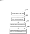
- FIG. 2 is a flowchart schematically illustrating a gas separation membrane cleaning method according to the present invention.
- a gas separation membrane cleaning device used to perform a gas separation membrane operation method according to the present invention includes a separation membrane module 10, a cleaning tank 20, a cleaning line 30, and a controller 40.
- the gas separation membrane operation method includes a separating process and a cleaning process.
- An inlet line 1 is connected to one side of the separation membrane module 10, and an outflow line 2 is connected to the other side of the separation membrane module 10.
- a separation line 3 is connected to a lateral surface of the separation membrane module 10.
- the inlet line 1, the outflow line 2, and the separation line 3 are each provided in the form of a pipe.
- the separation membrane module 10 is provided in the form of an extending pipe and has a plurality of separation membranes 11 provided as a bundle of separation membranes.
- the separation membrane 11 may be a CO 2 trapping separation membrane that separates CO 2 from N 2 .
- the controller 40 controls a pump (not illustrated) or the like and introduces an external gas into the separation membrane module 10 through the inlet line 1 from the gas injector (s10).
- the external gas is a separation target gas to be separated by the gas separation membrane during the separating process and distinguished from a gas used to clean the separation membrane during the cleaning process to be described below.
- the separation membrane module 10 separates the external gas into a permeable gas and an impermeable gas depending on permeability with respect to the separation membrane 11.
- the permeable gas is transferred to the separation line 3, and the impermeable gas is transferred to the outflow line 2 (s20).
- the permeable gas is a gas that has higher permeability with respect to the separation membrane 11 of the separation membrane module 10 and passes through the separation membrane 11.
- the impermeable gas is a gas having relatively lower permeability with respect to the separation membrane 11 than the permeable gas.
- the plurality of separation membranes 11 of the separation membrane module 10 is arranged in a horizontal direction in the drawing.
- the separation membrane module 10 is configured such that the permeable gas having passed through the separation membrane 11 is discharged in a direction perpendicular to the direction in which the separation membranes 11 are arranged, and the impermeable gas, which cannot pass through the separation membrane 11, is discharged in a direction identical to the direction in which the separation membranes 11 are arranged.
- One side of each of the separation membranes 11 of the separation membrane module 10 communicates with the inlet line 1, and the other side of each of the separation membranes 11 communicates with the outflow line 2.
- An external space of the separation membrane 11 communicates with the separation line 3.
- the permeable gas among the gases injected into the inlet line 1, passes through the separation membrane 11 in a radial direction and passes through the external space of the separation membrane 11.
- the permeable gas is separated and flows into the separation line 3 that communicates with the external space of the separation membrane 11.
- the impermeable gas among the external gases injected into the inlet line 1, is introduced into the separation membrane 11, moved in a longitudinal direction of the separation membrane 11, and transferred to the outflow line 2 that communicates with the other side of the separation membrane 11.
- the contamination of and damage to the separation membrane 11 is caused by main factors, such as dust, moisture, NOx, SOx, and the like.
- the sources of contamination which remains in small amount after the introduced gases are preprocessed, are accumulated in the separation membrane module 10. These substances react with moisture over time and cause the contamination of and damage to the membrane, which adversely affects separation efficiency of the separation membrane module 10.
- NOx and Sox react with moisture and create acid, it is necessary to minimize the accumulation of moisture, NOx, and SOx in the separation membrane.
- the cleaning process of injecting at least a part of the impermeable gas, which is transferred to the outflow line 2, into an inlet 12 of the separation membrane module 10 is performed separately from the separating process (s30).
- the cleaning tank 20 is connected to the outflow line 2, and at least a part of the impermeable gas is stored in the cleaning tank 20.
- the cleaning tank 20 is provided at a rear end of the gas separation membrane cleaning device.
- the cleaning tank 20 stores a predetermined amount of impermeable gas that is separated from the separation membrane module 10 and discarded.
- the impermeable gas which remains after the introduced gases are separated, is mainly N2, O2, CO2, CO, and the like.
- the impermeable gas is configured as a gas having lower permeability than the permeable gas.
- the impermeable gas which is not stored in the cleaning tank 20, is discharged to the outside through a discharge line 4.
- the cleaning tank 20 does not store the gas, which is supplied from the outside, except for the impermeable gas.
- the cleaning tank 20 uses the impermeable gas stored in the cleaning tank 20 to clean the separation membrane module 10. This configuration will be described in detail below.
- the cleaning line 30 is connected to the inlet 12 of the separation membrane module 10, and the other side of the cleaning line 30 is connected to the cleaning tank 20.
- the cleaning line 30 is provided in the form of a pipe.
- the impermeable gas stored in the cleaning tank 20 is supplied, at a pressure higher than a production pressure, to the cleaning line 30 from the cleaning tank 20.
- the cleaning line 30 defines a route through which the impermeable gas, which is supplied from the cleaning tank 20, is injected into the inlet 12 of the separation membrane module 10 through a valve 31.
- the controller 40 injects the impermeable gas, which is supplied to the cleaning line 30 from the cleaning tank 20, into the inlet 12 of the separation membrane module 10 through the valve 31.
- the cleaning line 30 may communicate with the inlet line 1 and connect the inlet line 1 to the inlet 12 of the separation membrane module 10
- the cleaning line 30 may communicate with an internal space of the separation membrane module 10 through the existing inlet line 1 without separately connecting the cleaning line 30 to the separation membrane module 10.
- the cleaning line 30 may be connected to the inlet 12 of the separation membrane module 10 independently of the inlet line 1.
- the external gas which is injected into the separation membrane module 10 during the separating process, is not introduced during the cleaning process according to the present invention, and the impermeable gas, which has already been used and stored in the cleaning tank 20, is circulated and injected into the inlet 12 of the separation membrane module 10 multiple times.
- the controller 40 may control the valve 31.
- the controller 40 may control the valve 31 so that the impermeable gas is circulated and injected into the inlet 12 of the separation membrane 11 in a predetermined cycle. Therefore, the impermeable gas, which is generated during the production process, is consistently supplied to the inlet 12 of the separation membrane 11, the source of contamination may be managed so as not to be accumulated in the separation membrane module 10.
- the impermeable gas may be injected into each of the separation membranes 11 of the separation membrane module 10 through the inlet 12 of the separation membrane module and detach and discharge the source of contamination in the separation membrane module 10.
- the impermeable gas is a gas generated during the production process, the impermeable gas may be smoothly circulated and supplied to clean the separation membrane module 10.
- the separation membrane 11 according to the present invention is the CO 2 trapping separation membrane
- the impermeable gas is mainly provided as N 2 . Because N 2 is stable in the separation membrane 11, it is possible to cope with the contamination of the separation membrane module 10 without separate chemical stimulus.
- the present invention may reduce operation costs by using the gas that is discarded among the separated gases. That is, according to the present invention, it is possible to recover and maintain the separation efficiency of the gas separation membrane that separates the gases. Further, it is possible to prevent contamination of the separation membrane module by using the discarded gas.
Landscapes
- Chemical & Material Sciences (AREA)
- Chemical Kinetics & Catalysis (AREA)
- Engineering & Computer Science (AREA)
- Analytical Chemistry (AREA)
- General Chemical & Material Sciences (AREA)
- Oil, Petroleum & Natural Gas (AREA)
- Separation Using Semi-Permeable Membranes (AREA)
Abstract
Description
- The present invention relates to a gas separation membrane operation method that cleans a gas separation membrane by using a gas separated by the gas separation membrane.
- Gas separation membranes are used to separate various gases, and recently, the use of gas separation membranes has increased. The technology related to the gas separation membrane in the related art focuses on a technology for manufacturing separation membranes and a technology for designing processes. However, technological developments to cope with contamination of the separation membrane, which directly causes deteriorations in separation membrane performance and lifespan, are insufficient.
- In the related art, in most cases, to reduce contamination of the separation membrane, efficiency in pre-processing an exhaust gas is increased before the exhaust gas is supplied to the separation membrane, and a contaminated separation membrane is replaced. However, in this case, there is a problem in that the contamination of or damage to the expensive separation membrane degrades separation efficiency, and the replacement of the separation membrane increases costs.
- To solve the problem, studies are being conducted to improve separation efficiency by removing contamination of the separation membrane by using external cleaning gases, water, chemical agents, and the like. However, the use of external cleaning gases or chemical agents causes problems of increases in operation costs, environmental pollution, and a need for secondary treatment.
- Patent Document 1 (
Korean Patent No. 10-1911786 - Patent Document 2 (
Japanese Patent Laid-Open No. 1995-136472 - An object of the present invention is to provide a gas separation membrane operation method capable of cleaning a gas separation membrane by reusing a gas that is to be discarded among gases separated by the gas separation membrane.
- The present invention provided to achieve the above-mentioned object, relates to a gas separation membrane cleaning method. The method may include (a) introducing an external gas into a separation membrane module through an inlet line, (b) separating, by the separation membrane module, the external gas into a permeable gas and an impermeable gas according to permeability with respect to a separation membrane, transferring the permeable gas to the separation line, and transferring the impermeable gas to the outflow line, and (c) injecting at least a part of the impermeable gas transferred to the outflow line into an inlet of the separation membrane module.
- According to the embodiment of the present invention, in step (c), the impermeable gas may be stored in a cleaning tank connected to the outflow line, and the impermeable gas stored in the cleaning tank may be injected into the inlet of the separation membrane module.
- According to the embodiment of the present invention, in step (c), the impermeable gas may be injected into the inlet of the separation membrane module through a cleaning line having one side connected to the cleaning tank, and the other side connected to a lateral portion of the inlet line.
- According to the embodiment of the present invention, in step (c), the impermeable gas may be circulated and injected multiple times without introducing the external gas.
- According to the present invention, it is possible to prevent the source of contamination from being accumulated in the separation membrane and improve separation efficiency by discharging the contaminants from the separation membrane. Because the gas discharged from the separation membrane is used, it is possible to ensure stability, improve the gas separation membrane performance and lifespan, and reduce operation costs and membrane replacement costs.
-
-
FIG. 1 is a cross-sectional side view schematically illustrating a gas separation membrane cleaning device used to perform a gas separation membrane operation method according to the present invention. -
FIG. 2 is a flowchart schematically illustrating a gas separation membrane cleaning method according to the present invention. - Hereinafter, specific contents for carrying out the present invention will be described with reference to the accompanying drawings. Further, in the description of the present invention, the specific descriptions of publicly known related functions will be omitted when it is determined that the specific descriptions may unnecessarily obscure the subject matter of the present invention.
-
FIG. 1 is a cross-sectional side view schematically illustrating a gas separation membrane cleaning device used to perform a gas separation membrane operation method according to the present invention.FIG. 2 is a flowchart schematically illustrating a gas separation membrane cleaning method according to the present invention. - With reference to
FIGS. 1 and2 , a gas separation membrane cleaning device used to perform a gas separation membrane operation method according to the present invention includes aseparation membrane module 10, acleaning tank 20, acleaning line 30, and acontroller 40. Hereinafter, the respective steps of the gas separation membrane operation method, which are performed by the gas separation membrane cleaning device, will be described with reference to the description of the respective components of the gas separation membrane cleaning device. The gas separation membrane operation method includes a separating process and a cleaning process. - The respective steps of the separating process of the gas separation membrane operation method will be described below.
- An inlet line 1 is connected to one side of the
separation membrane module 10, and an outflow line 2 is connected to the other side of theseparation membrane module 10. Aseparation line 3 is connected to a lateral surface of theseparation membrane module 10. The inlet line 1, the outflow line 2, and theseparation line 3 are each provided in the form of a pipe. Theseparation membrane module 10 is provided in the form of an extending pipe and has a plurality ofseparation membranes 11 provided as a bundle of separation membranes. For example, theseparation membrane 11 may be a CO2 trapping separation membrane that separates CO2 from N2. - One side of the inlet line 1 is connected to a gas injector (not illustrated) for injecting an external gas at high pressure, and the other side of the inlet line 1 is connected to the
separation membrane module 10. Thecontroller 40 controls a pump (not illustrated) or the like and introduces an external gas into theseparation membrane module 10 through the inlet line 1 from the gas injector (s10). The external gas is a separation target gas to be separated by the gas separation membrane during the separating process and distinguished from a gas used to clean the separation membrane during the cleaning process to be described below. - Next, the
separation membrane module 10 separates the external gas into a permeable gas and an impermeable gas depending on permeability with respect to theseparation membrane 11. The permeable gas is transferred to theseparation line 3, and the impermeable gas is transferred to the outflow line 2 (s20). The permeable gas is a gas that has higher permeability with respect to theseparation membrane 11 of theseparation membrane module 10 and passes through theseparation membrane 11. The impermeable gas is a gas having relatively lower permeability with respect to theseparation membrane 11 than the permeable gas. - The plurality of
separation membranes 11 of theseparation membrane module 10 is arranged in a horizontal direction in the drawing. Theseparation membrane module 10 is configured such that the permeable gas having passed through theseparation membrane 11 is discharged in a direction perpendicular to the direction in which theseparation membranes 11 are arranged, and the impermeable gas, which cannot pass through theseparation membrane 11, is discharged in a direction identical to the direction in which theseparation membranes 11 are arranged. - One side of each of the
separation membranes 11 of theseparation membrane module 10 communicates with the inlet line 1, and the other side of each of theseparation membranes 11 communicates with the outflow line 2. An external space of theseparation membrane 11 communicates with theseparation line 3. - The permeable gas, among the gases injected into the inlet line 1, passes through the
separation membrane 11 in a radial direction and passes through the external space of theseparation membrane 11. The permeable gas is separated and flows into theseparation line 3 that communicates with the external space of theseparation membrane 11. - The impermeable gas, among the external gases injected into the inlet line 1, is introduced into the
separation membrane 11, moved in a longitudinal direction of theseparation membrane 11, and transferred to the outflow line 2 that communicates with the other side of theseparation membrane 11. - The contamination of and damage to the
separation membrane 11 is caused by main factors, such as dust, moisture, NOx, SOx, and the like. The sources of contamination, which remains in small amount after the introduced gases are preprocessed, are accumulated in theseparation membrane module 10. These substances react with moisture over time and cause the contamination of and damage to the membrane, which adversely affects separation efficiency of theseparation membrane module 10. In addition, because NOx and Sox react with moisture and create acid, it is necessary to minimize the accumulation of moisture, NOx, and SOx in the separation membrane. - The respective steps of the cleaning process of the gas separation membrane operation method will be described below.
- After the separating process of introducing the external gas into the
separation membrane module 10 and separating the gases is performed, the cleaning process of injecting at least a part of the impermeable gas, which is transferred to the outflow line 2, into aninlet 12 of theseparation membrane module 10 is performed separately from the separating process (s30). - The
cleaning tank 20 is connected to the outflow line 2, and at least a part of the impermeable gas is stored in thecleaning tank 20. Thecleaning tank 20 is provided at a rear end of the gas separation membrane cleaning device. Thecleaning tank 20 stores a predetermined amount of impermeable gas that is separated from theseparation membrane module 10 and discarded. The impermeable gas, which remains after the introduced gases are separated, is mainly N2, O2, CO2, CO, and the like. The impermeable gas is configured as a gas having lower permeability than the permeable gas. - The impermeable gas, which is not stored in the
cleaning tank 20, is discharged to the outside through a discharge line 4. Thecleaning tank 20 does not store the gas, which is supplied from the outside, except for the impermeable gas. As described below, when theseparation membrane module 10 is contaminated, thecleaning tank 20 uses the impermeable gas stored in thecleaning tank 20 to clean theseparation membrane module 10. This configuration will be described in detail below. - One side of the
cleaning line 30 is connected to theinlet 12 of theseparation membrane module 10, and the other side of thecleaning line 30 is connected to thecleaning tank 20. Thecleaning line 30 is provided in the form of a pipe. The impermeable gas stored in thecleaning tank 20 is supplied, at a pressure higher than a production pressure, to thecleaning line 30 from thecleaning tank 20. Thecleaning line 30 defines a route through which the impermeable gas, which is supplied from thecleaning tank 20, is injected into theinlet 12 of theseparation membrane module 10 through avalve 31. Thecontroller 40 injects the impermeable gas, which is supplied to thecleaning line 30 from thecleaning tank 20, into theinlet 12 of theseparation membrane module 10 through thevalve 31. - Because one side of the
cleaning line 30 may communicate with the inlet line 1 and connect the inlet line 1 to theinlet 12 of theseparation membrane module 10, thecleaning line 30 may communicate with an internal space of theseparation membrane module 10 through the existing inlet line 1 without separately connecting thecleaning line 30 to theseparation membrane module 10. However, thecleaning line 30 may be connected to theinlet 12 of theseparation membrane module 10 independently of the inlet line 1. - Meanwhile, the external gas, which is injected into the
separation membrane module 10 during the separating process, is not introduced during the cleaning process according to the present invention, and the impermeable gas, which has already been used and stored in thecleaning tank 20, is circulated and injected into theinlet 12 of theseparation membrane module 10 multiple times. Thecontroller 40 may control thevalve 31. Thecontroller 40 may control thevalve 31 so that the impermeable gas is circulated and injected into theinlet 12 of theseparation membrane 11 in a predetermined cycle. Therefore, the impermeable gas, which is generated during the production process, is consistently supplied to theinlet 12 of theseparation membrane 11, the source of contamination may be managed so as not to be accumulated in theseparation membrane module 10. - The impermeable gas may be injected into each of the
separation membranes 11 of theseparation membrane module 10 through theinlet 12 of the separation membrane module and detach and discharge the source of contamination in theseparation membrane module 10. - Therefore, it is possible to improve efficiency and lifespan of the
separation membrane module 10. In addition, because a separate chemical agent is not used, it is possible to minimize negative influence on theseparation membrane 11. Because the impermeable gas is a gas generated during the production process, the impermeable gas may be smoothly circulated and supplied to clean theseparation membrane module 10. For example, in case that theseparation membrane 11 according to the present invention is the CO2 trapping separation membrane, the impermeable gas is mainly provided as N2. Because N2 is stable in theseparation membrane 11, it is possible to cope with the contamination of theseparation membrane module 10 without separate chemical stimulus. - According to the embodiments of the present invention, it is possible to minimize contamination and damage that occur when the gas separation membrane is used to separate the gases. Further, it is possible to prolong the lifespan of the separation membrane. Unlike the method in the related art that generally uses external gas or water, the present invention may reduce operation costs by using the gas that is discarded among the separated gases. That is, according to the present invention, it is possible to recover and maintain the separation efficiency of the gas separation membrane that separates the gases. Further, it is possible to prevent contamination of the separation membrane module by using the discarded gas.
- The protective scope in this field is not limited to the description and expression of the embodiments explicitly described above. In addition, it is reiterated that the scope of protection of the present invention should not be limited by the substitutions or modifications which are obvious in the art.
-
- 1: Inlet line
- 2: Outflow line
- 3: Separation line
- 4: Discharge line
- 10: Separation membrane module
- 11: Separation membrane
- 12: Inlet of separation membrane module
- 20: Cleaning tank
- 30: Cleaning line
- 31: Valve
- 40: Controller
Claims (4)
- A gas separation membrane operation method comprising:(a) introducing an external gas into a separation membrane module through an inlet line;(b) separating, by the separation membrane module, the external gas into a permeable gas and an impermeable gas according to permeability with respect to a separation membrane, transferring the permeable gas to the separation line, and transferring the impermeable gas to the outflow line; and(c) injecting at least a part of the impermeable gas transferred to the outflow line into an inlet of the separation membrane module.
- The gas separation membrane operation method of claim 1, wherein in step (c), the impermeable gas is stored in a cleaning tank connected to the outflow line, and the impermeable gas stored in the cleaning tank is injected into the inlet of the separation membrane module.
- The gas separation membrane operation method of claim 2, wherein in step (c), the impermeable gas is injected into the inlet of the separation membrane module through a cleaning line having one side connected to the cleaning tank, and the other side connected to a lateral portion of the inlet line.
- The gas separation membrane operation method of claim 1, wherein in step (c), the impermeable gas is circulated and injected multiple times without introducing the external gas.
Applications Claiming Priority (2)
| Application Number | Priority Date | Filing Date | Title |
|---|---|---|---|
| KR1020200165170A KR102503150B1 (en) | 2020-11-30 | 2020-11-30 | Gas separation membrane operation method |
| PCT/KR2021/017846 WO2022114914A1 (en) | 2020-11-30 | 2021-11-30 | Gas separation membrane operation method |
Publications (2)
| Publication Number | Publication Date |
|---|---|
| EP4252893A1 true EP4252893A1 (en) | 2023-10-04 |
| EP4252893A4 EP4252893A4 (en) | 2024-11-06 |
Family
ID=81755832
Family Applications (1)
| Application Number | Title | Priority Date | Filing Date |
|---|---|---|---|
| EP21898739.4A Pending EP4252893A4 (en) | 2020-11-30 | 2021-11-30 | METHOD FOR OPERATING A GAS SEPARATION MEMBRANE |
Country Status (6)
| Country | Link |
|---|---|
| US (1) | US12533629B2 (en) |
| EP (1) | EP4252893A4 (en) |
| JP (1) | JP7631525B2 (en) |
| KR (1) | KR102503150B1 (en) |
| CN (1) | CN116710192A (en) |
| WO (1) | WO2022114914A1 (en) |
Family Cites Families (28)
| Publication number | Priority date | Publication date | Assignee | Title |
|---|---|---|---|---|
| US4645516A (en) * | 1985-05-24 | 1987-02-24 | Union Carbide Corporation | Enhanced gas separation process |
| JPS6242723A (en) | 1985-08-20 | 1987-02-24 | Ube Ind Ltd | Mixed gas dehumidification method |
| US5030251A (en) | 1989-10-30 | 1991-07-09 | Permea, Inc. | System and method for separating a portion of a gas from a mixture of gases |
| US5169412A (en) | 1991-11-20 | 1992-12-08 | Praxair Technology Inc. | Membrane air drying and separation operations |
| JPH07136472A (en) | 1993-11-17 | 1995-05-30 | Miura Co Ltd | Method and apparatus for washing gas separation membrane |
| JPH0852316A (en) | 1994-07-15 | 1996-02-27 | Praxair Technol Inc | Improved previous purification of gas |
| CA2215777C (en) * | 1996-05-16 | 2006-01-03 | Kishore J. Doshi | Process for shut-down of a membrane operation |
| JP4617614B2 (en) | 2001-06-27 | 2011-01-26 | 宇部興産株式会社 | Hollow fiber separation membrane module and gas separation method |
| CA2558116A1 (en) | 2002-12-18 | 2004-07-01 | Ismael Touri | A system and apparatus for removal of unwanted substances in a gas flow |
| JP4987467B2 (en) | 2003-01-24 | 2012-07-25 | シー・エム・エス・テクノロジーズ・ホールディングス・インコーポレイテッド | Circulating membrane separation process |
| US7682422B2 (en) * | 2004-02-19 | 2010-03-23 | Ube Industries, Ltd. | Method for separating/recovering oxygen-rich air from air, its apparatus and gas separation membrane module |
| US8182592B2 (en) * | 2006-12-29 | 2012-05-22 | Ube Industries, Ltd. | Shell feed type gas separation membrane module |
| KR20110117465A (en) | 2010-04-21 | 2011-10-27 | 주식회사 씨엔엘에너지 | Continuous gas separation device and continuous gas separation method |
| PL2588217T3 (en) * | 2010-07-01 | 2017-08-31 | Evonik Fibres Gmbh | Process for separation of gases |
| US9718023B2 (en) * | 2010-11-04 | 2017-08-01 | Ube Industries, Ltd. | Gas separation membrane module and gas separation method |
| DE102011056633B4 (en) * | 2011-12-19 | 2014-02-13 | Highq-Factory Gmbh | Method for cleaning a filter |
| KR101514801B1 (en) | 2013-06-25 | 2015-04-24 | (주)파인텍 | The separation and recycling system for a perfluoro compounds |
| KR20150005008A (en) | 2013-07-04 | 2015-01-14 | 코웨이 주식회사 | Maintenance chemical cleaning method of separation membrane and Maintenance chemical cleaning system thereof |
| JP6645983B2 (en) * | 2014-11-18 | 2020-02-14 | 住友化学株式会社 | Carbon dioxide gas separation membrane, method for producing the same, and carbon dioxide gas separation membrane module |
| US20170001148A1 (en) * | 2015-06-30 | 2017-01-05 | Air Liquide Advanced Technologies U.S. Llc | Gas separation membrane module for reactive gas service |
| KR101840732B1 (en) * | 2016-01-06 | 2018-05-04 | 한국과학기술연구원 | Apparatus and method for bidirectional high permeable gas separation |
| KR101783429B1 (en) * | 2016-01-06 | 2017-09-29 | 한국과학기술연구원 | Apparatus and method for recovery of high permeable gas |
| WO2017146589A1 (en) | 2016-02-25 | 2017-08-31 | Hydrogen Mem-Tech As | Hydrogen production from natural gas in combination with injection of co2 for enhanced oil recovery |
| JP2018183756A (en) | 2017-04-27 | 2018-11-22 | 宇部興産株式会社 | Regeneration method of separation membrane module |
| US10561978B2 (en) * | 2017-08-09 | 2020-02-18 | Generon Igs, Inc. | Membrane-based gas separation with retentate sweep |
| KR101911786B1 (en) | 2018-07-16 | 2019-01-04 | 한국산업기술시험원 | Device and method for cleaning gas separation membrane |
| US20210370237A1 (en) | 2018-10-05 | 2021-12-02 | Terapore Technologies, Inc. | Method of filtering liquids or gases for electronics production |
| JP2025025884A (en) * | 2023-08-10 | 2025-02-21 | 日立Geニュークリア・エナジー株式会社 | Gas separation membrane, gas separation membrane module and gas permeation device |
-
2020
- 2020-11-30 KR KR1020200165170A patent/KR102503150B1/en active Active
-
2021
- 2021-11-30 CN CN202180090676.2A patent/CN116710192A/en active Pending
- 2021-11-30 US US18/254,645 patent/US12533629B2/en active Active
- 2021-11-30 JP JP2023532533A patent/JP7631525B2/en active Active
- 2021-11-30 WO PCT/KR2021/017846 patent/WO2022114914A1/en not_active Ceased
- 2021-11-30 EP EP21898739.4A patent/EP4252893A4/en active Pending
Also Published As
| Publication number | Publication date |
|---|---|
| JP2023551505A (en) | 2023-12-08 |
| US12533629B2 (en) | 2026-01-27 |
| KR20220076219A (en) | 2022-06-08 |
| EP4252893A4 (en) | 2024-11-06 |
| WO2022114914A1 (en) | 2022-06-02 |
| CN116710192A (en) | 2023-09-05 |
| KR102503150B1 (en) | 2023-02-23 |
| JP7631525B2 (en) | 2025-02-18 |
| US20240001292A1 (en) | 2024-01-04 |
Similar Documents
| Publication | Publication Date | Title |
|---|---|---|
| KR102162347B1 (en) | Ship | |
| US8551226B2 (en) | Exhaust gas treating system using polymer membrane for carbon dioxide capture process | |
| CA2877611C (en) | Air pollution control apparatus | |
| KR102316871B1 (en) | Gas Scrubber Device | |
| CN115301081A (en) | Cleaning and draining treatment device for ship waste gas | |
| KR20190105283A (en) | Complex filtering system of dust, SOx and NOx | |
| US20120018367A1 (en) | Membrane separator | |
| US12533629B2 (en) | Gas separation membrane operation method | |
| KR101757984B1 (en) | Apparatus for purifying exhaust gas of vessel | |
| US11439942B2 (en) | Gas purification apparatus, ship including the same, and gas purification method | |
| KR20150056104A (en) | Simultaneous reduction of sulfur oxides, nitrogen oxides and carbon dioxide in exhaust gas | |
| JP4188226B2 (en) | Filtration device and filtration method using the filtration device | |
| US9440181B2 (en) | Back-up configurations and method for sulfuric acid plants | |
| KR20190111479A (en) | Continuous Flue gas Desulfurization System | |
| JP2010058014A (en) | Method of cleaning membrane separation device and cleaning device | |
| JP2014184354A (en) | Processing system of ink discharge water | |
| KR20130118126A (en) | Method of cleaning membrance module for purifying water with physical back washing and purifying water system using the same | |
| KR102256309B1 (en) | A Control method of ship exhaust gas treatment apparatus | |
| KR102224365B1 (en) | A Control method of ship exhaust gas treatment apparatus | |
| KR20220142903A (en) | Pou scrubber that treats waste gases from semiconductor and display processes | |
| KR20200095845A (en) | Water purifying device | |
| JPS6354988A (en) | Removing device for water soluble organic solvent | |
| JP3395274B2 (en) | Membrane separation device |
Legal Events
| Date | Code | Title | Description |
|---|---|---|---|
| STAA | Information on the status of an ep patent application or granted ep patent |
Free format text: STATUS: THE INTERNATIONAL PUBLICATION HAS BEEN MADE |
|
| PUAI | Public reference made under article 153(3) epc to a published international application that has entered the european phase |
Free format text: ORIGINAL CODE: 0009012 |
|
| STAA | Information on the status of an ep patent application or granted ep patent |
Free format text: STATUS: REQUEST FOR EXAMINATION WAS MADE |
|
| 17P | Request for examination filed |
Effective date: 20230526 |
|
| AK | Designated contracting states |
Kind code of ref document: A1 Designated state(s): AL AT BE BG CH CY CZ DE DK EE ES FI FR GB GR HR HU IE IS IT LI LT LU LV MC MK MT NL NO PL PT RO RS SE SI SK SM TR |
|
| DAV | Request for validation of the european patent (deleted) | ||
| DAX | Request for extension of the european patent (deleted) | ||
| A4 | Supplementary search report drawn up and despatched |
Effective date: 20241004 |
|
| RIC1 | Information provided on ipc code assigned before grant |
Ipc: B01D 63/02 20060101ALN20240927BHEP Ipc: B01D 53/22 20060101ALI20240927BHEP Ipc: B01D 65/08 20060101ALI20240927BHEP Ipc: B01D 65/02 20060101AFI20240927BHEP |
|
| P01 | Opt-out of the competence of the unified patent court (upc) registered |
Free format text: CASE NUMBER: APP_57719/2024 Effective date: 20241022 |