EP4252866A1 - Continuous cable installation of fire detection links - Google Patents
Continuous cable installation of fire detection links Download PDFInfo
- Publication number
- EP4252866A1 EP4252866A1 EP23164150.7A EP23164150A EP4252866A1 EP 4252866 A1 EP4252866 A1 EP 4252866A1 EP 23164150 A EP23164150 A EP 23164150A EP 4252866 A1 EP4252866 A1 EP 4252866A1
- Authority
- EP
- European Patent Office
- Prior art keywords
- support plate
- main body
- fire suppression
- detection bracket
- actuation cable
- Prior art date
- Legal status (The legal status is an assumption and is not a legal conclusion. Google has not performed a legal analysis and makes no representation as to the accuracy of the status listed.)
- Pending
Links
Images


Classifications
-
- A—HUMAN NECESSITIES
- A62—LIFE-SAVING; FIRE-FIGHTING
- A62C—FIRE-FIGHTING
- A62C37/00—Control of fire-fighting equipment
- A62C37/36—Control of fire-fighting equipment an actuating signal being generated by a sensor separate from an outlet device
- A62C37/46—Construction of the actuator
- A62C37/48—Thermally sensitive initiators
-
- A—HUMAN NECESSITIES
- A62—LIFE-SAVING; FIRE-FIGHTING
- A62C—FIRE-FIGHTING
- A62C37/00—Control of fire-fighting equipment
- A62C37/36—Control of fire-fighting equipment an actuating signal being generated by a sensor separate from an outlet device
- A62C37/38—Control of fire-fighting equipment an actuating signal being generated by a sensor separate from an outlet device by both sensor and actuator, e.g. valve, being in the danger zone
- A62C37/42—Control of fire-fighting equipment an actuating signal being generated by a sensor separate from an outlet device by both sensor and actuator, e.g. valve, being in the danger zone with mechanical connection between sensor and actuator, e.g. rods, levers
-
- A—HUMAN NECESSITIES
- A62—LIFE-SAVING; FIRE-FIGHTING
- A62C—FIRE-FIGHTING
- A62C3/00—Fire prevention, containment or extinguishing specially adapted for particular objects or places
- A62C3/006—Fire prevention, containment or extinguishing specially adapted for particular objects or places for kitchens or stoves
Definitions
- Embodiments of the present invention relate to a detection bracket for use in a fire suppression system, and a fire suppression system.
- Some embodiments comprise a fusible mechanical linkage, and more particularly to fusible mechanical linkages for controlling tension in fire suppression system activation cables.
- Fire suppression systems such as in commercial kitchens, commonly include a suppressant reservoir housing a fire suppressant.
- a valve retains the suppressant in the reservoir until fire is detected, at which point the valve is actuated to allow suppressant to issue from the reservoir and into the area protected by the fire suppression system. Actuation typically occurs by operation of a fusible link and cable, which connects the fusible link to the valve.
- Fusible links are mechanical devices that generally consist of two pieces of metal connected to one another by a fusible alloy. Below a specific temperature the fusible alloy fixes the two pieces of metal to one another. When exposed to temperatures above the specific temperature the fusible alloy softens, allowing the two pieces of metal to separate from one another with relatively little force.
- fusible links In fire suppression systems fusible links generally communicate cable tension until the specific temperature is reached-at which point the tension present in the cable breaks the fusible link and unloads to actuate the valve. Fusible links are commonly employed in cooperation with cable take-up devices, which remove slack and load the cable in tension.
- a detection bracket for use in a fire suppression system includes a main body and at least one support plate positioned adjacent to the main body.
- the at least one support plate has an opening formed therein for receiving an actuation cable wrapped about the main body.
- the at least one support plate is movable from a first position to a second position relative to the main body in response to a predetermined condition. A tension in the actuation cable receivable within the opening is less when the at least one support plate is in the second position than when the at least one support plate is in the first position.
- the predetermined condition may be a temperature at or above a temperature threshold.
- the main body and the at least one support plate are in overlapping arrangement when the at least one support plate is in the first position.
- the at least one support plate is laterally offset from the main body when the at least one support plate is in the second position.
- the main body and at least a portion of the at least one support plate are in overlapping arrangement when the at least one support plate is in the second position.
- the detection bracket may comprise a fusible linkage disposed between the at least one support plate and the main body, the fusible linkage fixing the at least one support plate to the main body in the first position.
- the at least one support plate further comprises a first support plate and a second support plate.
- the first support plate is movable relative to the main body between the first position and the second position, and the second support plate is stationary.
- both the first support plate and the second support plate are movable from the first position to the second position relative to the main body in response to the predetermined condition.
- the detection bracket may comprise an actuation cable extending around a major surface of the main body and through the opening formed in the at least one support plate.
- a detection bracket for use in a fire suppression system includes a main body having a major surface and at least one support plate positioned adjacent to the main body.
- the at least one support plate has an opening formed therein for receiving an actuation cable wrapped about the major surface.
- a fusible linkage is disposed between the at least one support plate and the main body. The fusible linkage affixes the at least one support plate to the main body below a predetermined temperature and allows tension carried by the actuation cable extending through the at least one support plate to move the at least one support plate relative to the main body at temperatures above the predetermined temperature.
- the main body and the at least one support plate are in overlapping arrangement.
- the at least one support plate is laterally offset from the main body.
- the at least one support plate is in overlapping arrangement with the main body.
- the at least one support plate further comprises a first support plate and a second support plate, and another fusible linkage is disposed between the first support plate and the second support plate.
- a fire suppression system includes at least one source of fire suppression agent and a plurality of detection brackets operably coupled to the at least one source of fire suppression agent by an actuation cable.
- At least one of the plurality of detection brackets includes a main body and at least one support plate positioned adjacent to the main body.
- the at least one support plate has an opening formed therein for receiving the actuation cable.
- the at least one support plate is movable from a first position to a second position relative to the main body in response to a predetermined condition to release a tension in the actuation cable and fire suppression agent is releasable from the at least one source of fire suppression agent in response to the release of tension in the actuation cable.
- the at least one detection bracket further comprises a fusible linkage disposed between the at least one support plate and the main body, the fusible linkage fixing the at least one support plate to the main body in the first position.
- the predetermined condition is a temperature of the fusible linkage, wherein the fusible linkage fixes the at least one support plate to the main body below a predetermined temperature and allows tension carried by the actuation cable extending through the at least one support plate to move the at least one support plate from the first position to the second position at temperatures above the predetermined temperature.
- the main body and the at least one support plate are in overlapping arrangement when the at least one support plate is in the first position.
- the at least one support plate is laterally offset from the main body when the at least one support plate is in the second position.
- the at least one support plate further comprises a first support plate and a second support plate and both the first support plate and the second support plate are movable from the first position to the second position relative to the main body in response to the predetermined condition.
- the fire suppression system 20 may be located separate or remotely from the cooking appliance 10, such as within a vent hood 12, or alternatively, may be integrated or housed at least partially within a portion of the cooking appliance 10. It should be understood that the configuration of the fire suppression system 20 may vary based on the overall structural design of the cooking appliance 10.
- the fire suppression system 20 includes one or more spray nozzles 22 associated with the cooking appliance 10 and a source of fire suppression agent 24 in the form of at least one self-contained pressurized canister. In embodiments including a plurality of cooking appliances 10, one or more spray nozzles 22 may be dedicated to each cooking appliance 10, or alternatively, one or more evenly spaced spray nozzles 22 may be used for all of the cooking appliances 10.
- the source of fire suppression agent 24 is arranged in fluid communication with the nozzles 22 via an agent delivery path defined by a delivery piping system 26.
- the fire suppression agent is allowed to flow through the delivery piping system 26 to the one or more spray nozzles 22 for release directly onto an adjacent cooking hazard area 14 of the one or more cooking appliances 10.
- the fire suppression agent can be selected from materials such as water, dry chemical agent, wet chemical agent, or the like.
- the source of fire suppression agent 24 may additionally contain a gas propellant for facilitating the movement of the fire suppression agent through the delivery piping system 26.
- the propellant is stored separately from the fire suppression agent are also contemplated herein.
- the fire suppression system 20 is actuated in response to a fire sensing device (illustrated schematically at 28), such as a smoke detector or a heat sensor, for example.
- a control box C will direct a signal to an actuator 30 to open a valve 32 to allow the fire suppression agent to flow from the source 24 to the nozzles 22.
- the fire sensing device is a heat sensor including an activator bulb.
- the fire suppression system 20 may include a manual activation system 34, also referred to herein as a manual pull station, configured to actuate the control box C to activate the valve 32 to initiate operation of the fire suppression system 20.
- the detection bracket 40 connectable to an actuation cable 42 and operable as a fire sensing device 28 within the fire suppression system 20 are illustrated.
- the detection bracket 40 includes a main body 44 and at least one support plate 46.
- the main body 44 has an elongated, generally rectangular configuration.
- the main body 44 has a generally circular cross-sectional configuration.
- a main body 44 having any suitable configuration is within the scope of the invention (e.g., to facilitate the displacement of the actuation cable 42 and the release of tension in the actuation cable 42 in the event of a fire).
- the main body 44 may include one or more features to facilitate installation or wrapping of the actuation cable 42 about the main body 44.
- V-shaped slots 48 are formed at opposite ends 50, 52 of the main body 44 through which the actuation cable 42 may extend.
- the feature of the main body 44 may alternatively or additionally include a groove, protrusion, or combination thereof that forms a track extending over a major surface 54 of the main body 44.
- the main body 44 may include a substantially flat or planar edge 56 arranged opposite the major surface 54, and the at least one support plate 46 may be positioned at or generally adjacent to the flat edge 56.
- the flat edge 56 is illustrated as being at a bottom of the main body 44, it should be understood that embodiments having another configuration, such as where the flat edge 56 is an upper surface for example, are within the scope of the invention.
- the detection bracket 40 includes a first support plate 46a and a second support plate 46b.
- the plurality of support plates 46a, 46b may be substantially identical, or alternatively, may have different configurations.
- the first support plate 46a and the second support plate 46b are substantially identical but are rotated 180 degrees relative to each other.
- Embodiments where the support plates 46a, 46b are arranged in another configuration are also within the scope of the invention.
- each support plate 46a, 46b has an opening or through hole 58 formed therein configured to receive the actuation cable 42.
- an end of the actuation cable 42 is woven through the opening 58 in the first support plate 46a, about the major surface 54 of the main body 44, and through the opening 58 formed in the second support plate 46b sequentially.
- One or more of the support plates 46a, 46b is movable relative to the main body 44 between a first position and a second position.
- first support plate 46a and the second support plate 46b are illustrated as being movable in the FIGS., embodiments where only one of the support plates 46a, 46b is movable are also within the scope of the invention.
- the movable support plates 46a, 46b are in overlapping arrangement with the main body 44.
- the support plates 46a, 46b are disposed vertically underneath the main body 44, adjacent to the flat edge 56.
- the second position shown in FIGS.
- the support plates 46a, 46b may be laterally offset from the main body 44 as shown, or alternatively, may be in partial overlapping arrangement with the main body 44. In embodiments where the support plate 46a, 46b partially overlaps the main body 44 in the second position, the portion of the support plate 46a, 46b in overlapping arrangement with the main body 44 in the second position is significantly less than when in the first position.
- the movable support plate 46a, 46b is configured to move, for example translate, between the first position and the second position in response to a predetermined condition.
- the at least one movable support plate such as the first support plate 46a is affixed to a portion of the main body 44, such as the edge 56 for example, via a fusible linkage.
- the second support plate 46b may be affixed to the first support plate 46a via a fusible linkage.
- the support plates 26a, 46b are shown as being stacked when connected by the fusible linkage, embodiments where abutting ends of the support plates 46a, 46b are connected by a fusible linkage are also contemplated herein.
- the fusible linkage arranged at the interface between the first and second support plates 46a, 46b is axially aligned with the fusible linkage arranged between the first support plate 46a and the main body 44.
- the fusible linkage has a melting point or temperature threshold associated with a hazard which the fire suppression system 20 is configured to detect.
- the fusible linkage is formed from a material, including but not limited to solder or braze, each of which has a melting point approximating that of a grease or cooking oil fire. Accordingly, in response to heat that exceeds the predetermined temperature or predetermined threshold, such as resulting from a fire, the fusible linkage softens, thereby allowing at least one of the support plates 46a, 46b to move relative to the main body 44.
- the support plates 46a, 46b will move outwardly in opposite directions, from the first position to the second position. This movement reduces the tension within the cable 42 by unwrapping the cable 42 from about major surface 54 of the main body 44.
- Multiple detection brackets 40 as described herein can be positioned over a span of a single, continuous actuation cable 42. Accordingly, the cutting and crimping operations associated with creating multiple terminated segments of cable between detection links can be eliminated (or at least reduced). In addition, the detection brackets 40 can be repositioned and reconfigured within the field without damaging the cable 42.
Landscapes
- Health & Medical Sciences (AREA)
- Public Health (AREA)
- Business, Economics & Management (AREA)
- Emergency Management (AREA)
- Fire-Detection Mechanisms (AREA)
Abstract
Description
- Embodiments of the present invention relate to a detection bracket for use in a fire suppression system, and a fire suppression system. Some embodiments comprise a fusible mechanical linkage, and more particularly to fusible mechanical linkages for controlling tension in fire suppression system activation cables.
- Fire suppression systems, such as in commercial kitchens, commonly include a suppressant reservoir housing a fire suppressant. A valve retains the suppressant in the reservoir until fire is detected, at which point the valve is actuated to allow suppressant to issue from the reservoir and into the area protected by the fire suppression system. Actuation typically occurs by operation of a fusible link and cable, which connects the fusible link to the valve.
- Fusible links are mechanical devices that generally consist of two pieces of metal connected to one another by a fusible alloy. Below a specific temperature the fusible alloy fixes the two pieces of metal to one another. When exposed to temperatures above the specific temperature the fusible alloy softens, allowing the two pieces of metal to separate from one another with relatively little force. In fire suppression systems fusible links generally communicate cable tension until the specific temperature is reached-at which point the tension present in the cable breaks the fusible link and unloads to actuate the valve. Fusible links are commonly employed in cooperation with cable take-up devices, which remove slack and load the cable in tension.
- Such conventional methods and systems have generally been considered satisfactory for their intended purpose. However, installing and adjusting fusible mechanical linkages and fire suppression systems, and servicing such linkages and systems, may be complicated and time-consuming due to the complication of the systems.
- According to a first aspect of the present invention, a detection bracket for use in a fire suppression system includes a main body and at least one support plate positioned adjacent to the main body. The at least one support plate has an opening formed therein for receiving an actuation cable wrapped about the main body. The at least one support plate is movable from a first position to a second position relative to the main body in response to a predetermined condition. A tension in the actuation cable receivable within the opening is less when the at least one support plate is in the second position than when the at least one support plate is in the first position.
- The predetermined condition may be a temperature at or above a temperature threshold.
- Optionally, the main body and the at least one support plate are in overlapping arrangement when the at least one support plate is in the first position.
- Optionally, the at least one support plate is laterally offset from the main body when the at least one support plate is in the second position.
- Optionally, the main body and at least a portion of the at least one support plate are in overlapping arrangement when the at least one support plate is in the second position.
- The detection bracket may comprise a fusible linkage disposed between the at least one support plate and the main body, the fusible linkage fixing the at least one support plate to the main body in the first position.
- Optionally, the at least one support plate further comprises a first support plate and a second support plate.
- Optionally, the first support plate is movable relative to the main body between the first position and the second position, and the second support plate is stationary.
- Optionally, both the first support plate and the second support plate are movable from the first position to the second position relative to the main body in response to the predetermined condition.
- The detection bracket may comprise an actuation cable extending around a major surface of the main body and through the opening formed in the at least one support plate.
- According to a second aspect of the invention, a detection bracket for use in a fire suppression system includes a main body having a major surface and at least one support plate positioned adjacent to the main body. The at least one support plate has an opening formed therein for receiving an actuation cable wrapped about the major surface. A fusible linkage is disposed between the at least one support plate and the main body. The fusible linkage affixes the at least one support plate to the main body below a predetermined temperature and allows tension carried by the actuation cable extending through the at least one support plate to move the at least one support plate relative to the main body at temperatures above the predetermined temperature.
- Optionally, at temperatures below the predetermined temperature, the main body and the at least one support plate are in overlapping arrangement.
- Optionally, at temperatures above the predetermined temperature, the at least one support plate is laterally offset from the main body.
- Optionally, at temperatures above the predetermined temperature, the at least one support plate is in overlapping arrangement with the main body.
- Optionally, the at least one support plate further comprises a first support plate and a second support plate, and another fusible linkage is disposed between the first support plate and the second support plate.
- According to a third aspect of the invention, a fire suppression system includes at least one source of fire suppression agent and a plurality of detection brackets operably coupled to the at least one source of fire suppression agent by an actuation cable. At least one of the plurality of detection brackets includes a main body and at least one support plate positioned adjacent to the main body. The at least one support plate has an opening formed therein for receiving the actuation cable. The at least one support plate is movable from a first position to a second position relative to the main body in response to a predetermined condition to release a tension in the actuation cable and fire suppression agent is releasable from the at least one source of fire suppression agent in response to the release of tension in the actuation cable.
- Optionally, the at least one detection bracket further comprises a fusible linkage disposed between the at least one support plate and the main body, the fusible linkage fixing the at least one support plate to the main body in the first position.
- Optionally, the predetermined condition is a temperature of the fusible linkage, wherein the fusible linkage fixes the at least one support plate to the main body below a predetermined temperature and allows tension carried by the actuation cable extending through the at least one support plate to move the at least one support plate from the first position to the second position at temperatures above the predetermined temperature.
- Optionally, the main body and the at least one support plate are in overlapping arrangement when the at least one support plate is in the first position.
- Optionally, the at least one support plate is laterally offset from the main body when the at least one support plate is in the second position.
- Optionally, the at least one support plate further comprises a first support plate and a second support plate and both the first support plate and the second support plate are movable from the first position to the second position relative to the main body in response to the predetermined condition.
- The following descriptions should not be considered limiting in any way. With reference to the accompanying drawings, like elements are numbered alike:
-
FIG. 1 is a schematic diagram of an exemplary system for delivering a fire suppression agent to at least one cooking appliance; -
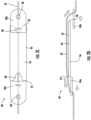
FIG. 2A is a bottom view of an exemplary detection bracket having support plates in a first position; -
FIG. 2B is a cross-sectional side view of the detection bracket ofFIG. 2A ; -
FIG. 2C is a bottom view of an exemplary detection bracket having support plates in a second position; -
FIG. 2D is a cross-sectional side view of the detection bracket ofFIG. 2C ; -
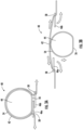
FIG. 3A is a side view of an exemplary detection bracket having support plates in a first position; and -
FIG. 3B is a side view of the detection bracket ofFIG. 3A having support plates in a second position. - A detailed description of one or more embodiments of the disclosed apparatus and method are presented herein by way of exemplification and not limitation with reference to the Figures.
- With reference now to
FIG. 1 , an example of a system 20 for delivering a fire suppression agent to one ormore cooking appliances 10 is illustrated. The fire suppression system 20 may be located separate or remotely from thecooking appliance 10, such as within avent hood 12, or alternatively, may be integrated or housed at least partially within a portion of thecooking appliance 10. It should be understood that the configuration of the fire suppression system 20 may vary based on the overall structural design of thecooking appliance 10. The fire suppression system 20 includes one ormore spray nozzles 22 associated with thecooking appliance 10 and a source offire suppression agent 24 in the form of at least one self-contained pressurized canister. In embodiments including a plurality ofcooking appliances 10, one ormore spray nozzles 22 may be dedicated to eachcooking appliance 10, or alternatively, one or more evenly spacedspray nozzles 22 may be used for all of thecooking appliances 10. - The source of
fire suppression agent 24 is arranged in fluid communication with thenozzles 22 via an agent delivery path defined by adelivery piping system 26. In the event of a fire, the fire suppression agent is allowed to flow through thedelivery piping system 26 to the one ormore spray nozzles 22 for release directly onto an adjacentcooking hazard area 14 of the one ormore cooking appliances 10. - Those skilled in the art will readily appreciate that the fire suppression agent can be selected from materials such as water, dry chemical agent, wet chemical agent, or the like. Further, the source of
fire suppression agent 24 may additionally contain a gas propellant for facilitating the movement of the fire suppression agent through thedelivery piping system 26. However, embodiments where the propellant is stored separately from the fire suppression agent are also contemplated herein. - In an embodiment, the fire suppression system 20 is actuated in response to a fire sensing device (illustrated schematically at 28), such as a smoke detector or a heat sensor, for example. In response to heat or smoke exceeding an allowable limit, a control box C will direct a signal to an
actuator 30 to open avalve 32 to allow the fire suppression agent to flow from thesource 24 to thenozzles 22. For example, in an embodiment the fire sensing device is a heat sensor including an activator bulb. When a fire is present, the increased heat resulting from the flames will cause the activator bulb to break, thereby releasing the tension on an actuation cable connecting the fire sensing device to the control box C. Alternatively, or in addition, the fire suppression system 20 may include amanual activation system 34, also referred to herein as a manual pull station, configured to actuate the control box C to activate thevalve 32 to initiate operation of the fire suppression system 20. - With reference now to
FIGS. 2A-3B , exemplary embodiments of adetection bracket 40 connectable to anactuation cable 42 and operable as afire sensing device 28 within the fire suppression system 20 are illustrated. In each of the embodiments, thedetection bracket 40 includes amain body 44 and at least one support plate 46. In the illustrated, non-limiting embodiment ofFIGS. 2A-2D , themain body 44 has an elongated, generally rectangular configuration. Alternatively, in the embodiment illustrated inFIGS. 3A and 3B , themain body 44 has a generally circular cross-sectional configuration. Accordingly, it should be understood that amain body 44 having any suitable configuration is within the scope of the invention (e.g., to facilitate the displacement of theactuation cable 42 and the release of tension in theactuation cable 42 in the event of a fire). In an embodiment, themain body 44 may include one or more features to facilitate installation or wrapping of theactuation cable 42 about themain body 44. For example, as shown inFIGS. 2A and2C , V-shapedslots 48 are formed at opposite ends 50, 52 of themain body 44 through which theactuation cable 42 may extend. Although not shown, the feature of themain body 44 may alternatively or additionally include a groove, protrusion, or combination thereof that forms a track extending over amajor surface 54 of themain body 44. - Regardless of the configuration of the
main body 44, themain body 44 may include a substantially flat orplanar edge 56 arranged opposite themajor surface 54, and the at least one support plate 46 may be positioned at or generally adjacent to theflat edge 56. Although theflat edge 56 is illustrated as being at a bottom of themain body 44, it should be understood that embodiments having another configuration, such as where theflat edge 56 is an upper surface for example, are within the scope of the invention. - In the illustrated, non-limiting embodiments shown in the FIGS., the
detection bracket 40 includes afirst support plate 46a and asecond support plate 46b. However, embodiments, having only a single support plate, or more than two support plates are also contemplated herein. The plurality ofsupport plates FIGS. 2A-2D and3A-3B , thefirst support plate 46a and thesecond support plate 46b are substantially identical but are rotated 180 degrees relative to each other. Embodiments where thesupport plates - As shown, each
support plate hole 58 formed therein configured to receive theactuation cable 42. In an embodiment, an end of theactuation cable 42 is woven through theopening 58 in thefirst support plate 46a, about themajor surface 54 of themain body 44, and through theopening 58 formed in thesecond support plate 46b sequentially. - One or more of the
support plates main body 44 between a first position and a second position. Although both thefirst support plate 46a and thesecond support plate 46b are illustrated as being movable in the FIGS., embodiments where only one of thesupport plates FIGS. 2A, 2B , and3A , themovable support plates main body 44. In the illustrated, non-limiting embodiment, thesupport plates main body 44, adjacent to theflat edge 56. In the second position, shown inFIGS. 2C, 2D , and3B , thesupport plates main body 44 as shown, or alternatively, may be in partial overlapping arrangement with themain body 44. In embodiments where thesupport plate main body 44 in the second position, the portion of thesupport plate main body 44 in the second position is significantly less than when in the first position. - The
movable support plate first support plate 46a is affixed to a portion of themain body 44, such as theedge 56 for example, via a fusible linkage. Alternatively, or in addition, thesecond support plate 46b may be affixed to thefirst support plate 46a via a fusible linkage. Although thesupport plates 26a, 46b are shown as being stacked when connected by the fusible linkage, embodiments where abutting ends of thesupport plates second support plates first support plate 46a and themain body 44. - The fusible linkage has a melting point or temperature threshold associated with a hazard which the fire suppression system 20 is configured to detect. In an embodiment, the fusible linkage is formed from a material, including but not limited to solder or braze, each of which has a melting point approximating that of a grease or cooking oil fire. Accordingly, in response to heat that exceeds the predetermined temperature or predetermined threshold, such as resulting from a fire, the fusible linkage softens, thereby allowing at least one of the
support plates main body 44. As a result of the tension acting on theactuation cable 42 connected to thesupport plates main body 44, thesupport plates cable 42 by unwrapping thecable 42 from aboutmajor surface 54 of themain body 44. -
Multiple detection brackets 40 as described herein can be positioned over a span of a single,continuous actuation cable 42. Accordingly, the cutting and crimping operations associated with creating multiple terminated segments of cable between detection links can be eliminated (or at least reduced). In addition, thedetection brackets 40 can be repositioned and reconfigured within the field without damaging thecable 42. - The term "about" is intended to include the degree of error associated with measurement of the particular quantity based upon the equipment available at the time of filing the application.
- The terminology used herein is for the purpose of describing particular embodiments only and is not intended to be limiting of the present invention. As used herein, the singular forms "a", "an" and "the" are intended to include the plural forms as well, unless the context clearly indicates otherwise. It will be further understood that the terms "comprises" and/or "comprising," when used in this specification, specify the presence of stated features, integers, steps, operations, elements, and/or components, but do not preclude the presence or addition of one or more other features, integers, steps, operations, element components, and/or groups thereof.
- While the present invention has been described with reference to an exemplary embodiment or embodiments, it will be understood by those skilled in the art that various changes may be made and equivalents may be substituted for elements thereof without departing from the scope of the present invention. In addition, many modifications may be made to adapt a particular situation or material to the teachings of the present invention without departing from the scope thereof. Therefore, it is intended that the present invention not be limited to the particular embodiment disclosed as the best mode contemplated for carrying out this present invention, but that the present invention will include all embodiments falling within the scope of the claims.
Claims (15)
- A detection bracket (40) for use in a fire suppression system, the detection bracket comprisinga main body (44);at least one support plate (46) positioned adjacent to the main body (44), the at least one support plate having an opening (58) formed therein for receiving an actuation cable (42) wrapped about the main body (44);wherein the at least one support plate (46) is movable from a first position to a second position relative to the main body (44) in response to a predetermined condition, wherein a tension in the actuation cable (42) receivable within the opening is less when the at least one support plate (46) is in the second position than when the at least one support plate is in the first position.
- The detection bracket of claim 1, wherein the predetermined condition is a temperature at or above a temperature threshold.
- The detection bracket of claim 1 or 2, wherein the main body (44) and the at least one support plate (46) are in overlapping arrangement when the at least one support plate is in the first position.
- The detection bracket of any preceding claim, wherein the at least one support plate (46) is laterally offset from the main body (44) when the at least one support plate is in the second position, or
wherein the main body (44) and at least a portion of the at least one support plate (46) are in overlapping arrangement when the at least one support plate is in the second position. - The detection bracket of any preceding claim, further comprising a fusible linkage disposed between the at least one support plate (46) and the main body (44), the fusible linkage fixing the at least one support plate (46) to the main body (44) in the first position.
- The detection bracket of any preceding claim, wherein the at least one support plate (46) further comprises a first support plate (46a) and a second support plate (46b).
- The detection bracket of claim 6, wherein the first support plate (46a) is movable relative to the main body (44) between the first position and the second position, and the second support (46b) plate is stationary, or
wherein both the first support plate (46a) and the second support plate (46b) are movable from the first position to the second position relative to the main body (44) in response to the predetermined condition. - A detection bracket (40) for use in a fire suppression system, the detection bracket comprising:a main body (44) having a major surface (54);at least one support plate (46) positioned adjacent to the main body (44), the at least one support plate having an opening (58) formed therein for receiving an actuation cable (42) wrapped about the major surface (54); anda fusible linkage disposed between the at least one support plate (46) and the main body (44), the fusible linkage fixing the at least one support plate (46) to the main body (44) below a predetermined temperature and allowing tension carried by the actuation cable (42) extending through the at least one support plate (46) to move the at least one support plate (46) relative to the main body (44) at temperatures above the predetermined temperature.
- The detection bracket of claim 8, wherein at temperatures below the predetermined temperature, the main body (44) and the at least one support plate (46) are in overlapping arrangement.
- The detection bracket of claim 8 or 9, wherein at temperatures above the predetermined temperature, the at least one support plate (46) is laterally offset from the main body (44), or
wherein at temperatures below the predetermined temperature, the at least one support plate (46) is in overlapping arrangement with the main body (44). - The detection bracket of any of claims 8 to 10, wherein the at least one support plate further comprises a first support plate (46a) and a second support plate (46b), and another fusible linkage is disposed between the first support plate (46a) and the second support plate (46b).
- A fire suppression system comprising:at least one source of fire suppression agent (24);a plurality of detection brackets (40) operably coupled to the at least one source of fire suppression agent by an actuation cable (42), at least one of the plurality of detection brackets comprising:a main body (44);at least one support plate (46) positioned adjacent to the main body, the at least one support plate having an opening (58) formed therein for receiving the actuation cable (42);wherein the at least one support plate (46) is movable from a first position to a second position relative to the main body (44) in response to a predetermined condition to release a tension in the actuation cable (42);wherein fire suppression agent is releasable from the at least one source of fire suppression agent (24) in response to the release of tension in the actuation cable (42).
- The fire suppression system of claim 12, wherein the at least one detection bracket (40) further comprises a fusible linkage disposed between the at least one support plate (46) and the main body (44), the fusible linkage fixing the at least one support plate (46) to the main body (44) in the first position,
wherein optionally the predetermined condition is a temperature of the fusible linkage, wherein the fusible linkage fixes the at least one support plate (46) to the main body (44) below a predetermined temperature and allows tension carried by the actuation cable (42) extending through the at least one support plate (46) to move the at least one support plate from the first position to the second position at temperatures above the predetermined temperature. - The fire suppression system of claim 12 or 13, wherein the main body (44) and the at least one support plate (46) are in overlapping arrangement when the at least one support plate is in the first position, or
wherein the at least one support plate (46) is laterally offset from the main body (44) when the at least one support plate is in the second position. - The fire suppression system of any of claims 12 to 14, wherein the at least one support plate further comprises a first support plate (46a) and a second support plate (46b) and both the first support plate (46a) and the second support plate (46b) are movable from the first position to the second position relative to the main body (44) in response to the predetermined condition.
Applications Claiming Priority (1)
| Application Number | Priority Date | Filing Date | Title |
|---|---|---|---|
| US202263325999P | 2022-03-31 | 2022-03-31 |
Publications (1)
| Publication Number | Publication Date |
|---|---|
| EP4252866A1 true EP4252866A1 (en) | 2023-10-04 |
Family
ID=85772755
Family Applications (1)
| Application Number | Title | Priority Date | Filing Date |
|---|---|---|---|
| EP23164150.7A Pending EP4252866A1 (en) | 2022-03-31 | 2023-03-24 | Continuous cable installation of fire detection links |
Country Status (2)
| Country | Link |
|---|---|
| US (1) | US20230310916A1 (en) |
| EP (1) | EP4252866A1 (en) |
Citations (2)
| Publication number | Priority date | Publication date | Assignee | Title |
|---|---|---|---|---|
| US5273119A (en) * | 1992-10-05 | 1993-12-28 | Dick John K | Tension release for fire protection system |
| US20210370115A1 (en) * | 2017-10-27 | 2021-12-02 | Carrier Corporation | Fusible mechanical linkages for fire suppression systems |
Family Cites Families (8)
| Publication number | Priority date | Publication date | Assignee | Title |
|---|---|---|---|---|
| US1508376A (en) * | 1920-03-15 | 1924-09-16 | Sydney F Weston | Fusible link |
| US3348617A (en) * | 1965-09-13 | 1967-10-24 | Fyr Fyter Co | Fusible link |
| US3463236A (en) * | 1967-12-05 | 1969-08-26 | Ansul Co | Cable release for fire protection system and the like |
| US5120152A (en) * | 1990-06-25 | 1992-06-09 | Carmen Gueli | Fusible link |
| US6404322B1 (en) * | 1999-02-12 | 2002-06-11 | Elsie Manufacturing Company, Inc. | Fusible link |
| JP4064217B2 (en) * | 2002-11-26 | 2008-03-19 | 内橋エステック株式会社 | Alloy type thermal fuse and material for thermal fuse element |
| US11602654B2 (en) * | 2019-10-01 | 2023-03-14 | Tyco Fire Products Lp | Ultra-high temperature fusible link |
| US11199286B1 (en) * | 2019-10-04 | 2021-12-14 | Evergreen Tool Company, Inc. | Bushing shield for fire detection |
-
2023
- 2023-03-24 EP EP23164150.7A patent/EP4252866A1/en active Pending
- 2023-03-28 US US18/191,121 patent/US20230310916A1/en active Pending
Patent Citations (2)
| Publication number | Priority date | Publication date | Assignee | Title |
|---|---|---|---|---|
| US5273119A (en) * | 1992-10-05 | 1993-12-28 | Dick John K | Tension release for fire protection system |
| US20210370115A1 (en) * | 2017-10-27 | 2021-12-02 | Carrier Corporation | Fusible mechanical linkages for fire suppression systems |
Also Published As
| Publication number | Publication date |
|---|---|
| US20230310916A1 (en) | 2023-10-05 |
Similar Documents
| Publication | Publication Date | Title |
|---|---|---|
| US11844971B2 (en) | Controlled system and methods for storage fire protection | |
| EP3626314B1 (en) | Dry sprinkler | |
| US9901763B2 (en) | Preaction sprinkler valve assemblies, related dry sprinkler devices and fire protection sprinkler systems | |
| US3463236A (en) | Cable release for fire protection system and the like | |
| US20190076686A1 (en) | Automatic fire extinguisher | |
| US20230310916A1 (en) | Continuous cable installation of fire detection links | |
| US5899278A (en) | Stove top fire extinguisher system | |
| CN105251171B (en) | Rapid pressure for fire extinguisher spreads actuator | |
| EP4169585B1 (en) | Cable pull station release mechanism | |
| WO2007008779A1 (en) | Thermal detector for fire suppression system | |
| US5771977A (en) | Automatic trigger mechanism for portable fire extinguishers | |
| US4449589A (en) | Fire containment device and method | |
| EP0229739A2 (en) | Fire extinguishing system | |
| EP4205817A1 (en) | Pull station release mechanism | |
| US11547889B2 (en) | Fusible mechanical linkages for fire suppression systems | |
| KR102920382B1 (en) | Automatic water fire extinguishers and related fire prevention equipment | |
| US12623102B2 (en) | Torsion release mechanical control node for cable operated fire suppression systems | |
| EP4260916B1 (en) | Hinged axle pulley release for inline cable fire pull station | |
| EP4349422B1 (en) | Fire suppression system comprising a line tension indicating device | |
| JPH0655655U (en) | Sensor nozzle for automatic fire extinguisher |
Legal Events
| Date | Code | Title | Description |
|---|---|---|---|
| PUAI | Public reference made under article 153(3) epc to a published international application that has entered the european phase |
Free format text: ORIGINAL CODE: 0009012 |
|
| STAA | Information on the status of an ep patent application or granted ep patent |
Free format text: STATUS: THE APPLICATION HAS BEEN PUBLISHED |
|
| AK | Designated contracting states |
Kind code of ref document: A1 Designated state(s): AL AT BE BG CH CY CZ DE DK EE ES FI FR GB GR HR HU IE IS IT LI LT LU LV MC ME MK MT NL NO PL PT RO RS SE SI SK SM TR |
|
| STAA | Information on the status of an ep patent application or granted ep patent |
Free format text: STATUS: REQUEST FOR EXAMINATION WAS MADE |
|
| 17P | Request for examination filed |
Effective date: 20240328 |
|
| RBV | Designated contracting states (corrected) |
Designated state(s): AL AT BE BG CH CY CZ DE DK EE ES FI FR GB GR HR HU IE IS IT LI LT LU LV MC ME MK MT NL NO PL PT RO RS SE SI SK SM TR |
|
| RAP1 | Party data changed (applicant data changed or rights of an application transferred) |
Owner name: KIDDE-FENWAL, LLC |
|
| P01 | Opt-out of the competence of the unified patent court (upc) registered |
Free format text: CASE NUMBER: APP_30602/2025 Effective date: 20250626 |