EP4252805A1 - Inhalation aid - Google Patents
Inhalation aid Download PDFInfo
- Publication number
- EP4252805A1 EP4252805A1 EP21897680.1A EP21897680A EP4252805A1 EP 4252805 A1 EP4252805 A1 EP 4252805A1 EP 21897680 A EP21897680 A EP 21897680A EP 4252805 A1 EP4252805 A1 EP 4252805A1
- Authority
- EP
- European Patent Office
- Prior art keywords
- main body
- body part
- inhalation
- port
- wall surface
- Prior art date
- Legal status (The legal status is an assumption and is not a legal conclusion. Google has not performed a legal analysis and makes no representation as to the accuracy of the status listed.)
- Granted
Links
Images


Classifications
-
- A—HUMAN NECESSITIES
- A61—MEDICAL OR VETERINARY SCIENCE; HYGIENE
- A61M—DEVICES FOR INTRODUCING MEDIA INTO, OR ONTO, THE BODY; DEVICES FOR TRANSDUCING BODY MEDIA OR FOR TAKING MEDIA FROM THE BODY; DEVICES FOR PRODUCING OR ENDING SLEEP OR STUPOR
- A61M11/00—Sprayers or atomisers specially adapted for therapeutic purposes
-
- A—HUMAN NECESSITIES
- A61—MEDICAL OR VETERINARY SCIENCE; HYGIENE
- A61M—DEVICES FOR INTRODUCING MEDIA INTO, OR ONTO, THE BODY; DEVICES FOR TRANSDUCING BODY MEDIA OR FOR TAKING MEDIA FROM THE BODY; DEVICES FOR PRODUCING OR ENDING SLEEP OR STUPOR
- A61M15/00—Inhalators
- A61M15/0086—Inhalation chambers
-
- A—HUMAN NECESSITIES
- A61—MEDICAL OR VETERINARY SCIENCE; HYGIENE
- A61M—DEVICES FOR INTRODUCING MEDIA INTO, OR ONTO, THE BODY; DEVICES FOR TRANSDUCING BODY MEDIA OR FOR TAKING MEDIA FROM THE BODY; DEVICES FOR PRODUCING OR ENDING SLEEP OR STUPOR
- A61M11/00—Sprayers or atomisers specially adapted for therapeutic purposes
- A61M11/001—Particle size control
- A61M11/002—Particle size control by flow deviation causing inertial separation of transported particles
-
- A—HUMAN NECESSITIES
- A61—MEDICAL OR VETERINARY SCIENCE; HYGIENE
- A61M—DEVICES FOR INTRODUCING MEDIA INTO, OR ONTO, THE BODY; DEVICES FOR TRANSDUCING BODY MEDIA OR FOR TAKING MEDIA FROM THE BODY; DEVICES FOR PRODUCING OR ENDING SLEEP OR STUPOR
- A61M11/00—Sprayers or atomisers specially adapted for therapeutic purposes
- A61M11/001—Particle size control
- A61M11/003—Particle size control by passing the aerosol trough sieves or filters
-
- A—HUMAN NECESSITIES
- A61—MEDICAL OR VETERINARY SCIENCE; HYGIENE
- A61M—DEVICES FOR INTRODUCING MEDIA INTO, OR ONTO, THE BODY; DEVICES FOR TRANSDUCING BODY MEDIA OR FOR TAKING MEDIA FROM THE BODY; DEVICES FOR PRODUCING OR ENDING SLEEP OR STUPOR
- A61M15/00—Inhalators
- A61M15/0001—Details of inhalators; Constructional features thereof
- A61M15/0021—Mouthpieces therefor
-
- A—HUMAN NECESSITIES
- A61—MEDICAL OR VETERINARY SCIENCE; HYGIENE
- A61M—DEVICES FOR INTRODUCING MEDIA INTO, OR ONTO, THE BODY; DEVICES FOR TRANSDUCING BODY MEDIA OR FOR TAKING MEDIA FROM THE BODY; DEVICES FOR PRODUCING OR ENDING SLEEP OR STUPOR
- A61M15/00—Inhalators
- A61M15/009—Inhalators using medicine packages with incorporated spraying means, e.g. aerosol cans
-
- A—HUMAN NECESSITIES
- A61—MEDICAL OR VETERINARY SCIENCE; HYGIENE
- A61M—DEVICES FOR INTRODUCING MEDIA INTO, OR ONTO, THE BODY; DEVICES FOR TRANSDUCING BODY MEDIA OR FOR TAKING MEDIA FROM THE BODY; DEVICES FOR PRODUCING OR ENDING SLEEP OR STUPOR
- A61M2206/00—Characteristics of a physical parameter; associated device therefor
- A61M2206/10—Flow characteristics
- A61M2206/20—Flow characteristics having means for promoting or enhancing the flow, actively or passively
Definitions
- the present invention relates to an inhalation aid mounted on a spout port of an atomization type inhaler for assisting inhalation of dispersed drugs.
- bronchial asthma and chronic obstructive pulmonary disease which are respiratory tract diseases
- suction therapy is one of the most effective treatment methods.
- a Dry Powder Inhaler (DPI) and a Metered-Dose Inhaler (MDI) are generally used for inhaling particulate drugs including, for example, an inhaled corticosteroid, a long-acting ⁇ 2 agonist, and a long-acting muscarinic antagonist.
- the Metered-Dose Inhaler is a type of inhaler for atomizing constant amounts of drug particles using gas pressure.
- the drug particles get transported to the human respiratory tract through the respiratory organs.
- an inhalation aid is sometimes attached to a spout port of the atomization type inhaler in order to further ensure patient inhalation of the drug particles.
- the inhalation aid also referred to as an inhalation spacer
- ones disclosed in PLT 1 and PLT 2 are known as examples.
- PLT 1 discloses a device that performs vaporization and dispersion of aerosol droplets for drug inhalation therapy.
- the device includes a main body having rotational symmetry, a tubular member arranged on one of front ends and protruding by a defined length into the main body, and an intake air member through which ambient air can flow into the main body when a patient inhales the aerosol stored in the main body via the other tubular member.
- an introduction port of the drug particles dispersed from the atomization type inhaler and an inhalation port for inhaling the drug particles are disposed in a straight line.
- the device in PLT 1 allows shifting the timing of dispersion by the atomization type inhaler from the inhalation timing just as much as the length of the main body, a large amount of the drug particles dispersed into the main body through the introduction port directly heads to the inhalation port. Therefore, the drug particles are required to be inhaled immediately after the drug particles are dispersed into the main body by the atomization type inhaler, and the timing adjustment effect is not in sufficient. Accordingly, a patient with poor inhalation ability may possibly still find it difficult to inhale the drug particles.
- PLT 2 discloses a device that is a spacer device for oral administration of a volatile medium containing drug particles.
- the spacer device includes a chamber having an introduction port, an outlet to be received in the mouth, and a butterfly valve.
- a main object of the present invention is to provide an inhalation aid that allows a patient to arbitrarily adjust a drug atomization timing with ease without relying on a valve structure.
- the present invention relates to an inhalation aid 100 for being mounted on a spout port of an atomization type inhaler.
- the inhalation aid 100 according to the present invention is applicable to a general Metered-Dose Inhaler (MDI).
- MDI Metered-Dose Inhaler
- the inhalation aid 100 of the present invention includes a main body part 10, an introduction port 20, a wall surface part 30, and an inhalation port 40.
- the main body part 10 has a tubular structure, and drug particles are dispersed into an internal space of the main body part 10 from the atomization type inhaler.
- the main body part 10 is preferred to have a reverse-tapered shape like as circular-truncated cone shape but may be any other polygonal shape including a triangular tubular shape, a rectangular tubular shape, or a pentagonal tubular shape.
- the introduction port 20 is an opening portion for introducing the drug particles dispersed from the spout port of the inhaler into the main body part 10, and is disposed on one end side of the main body part 10.
- the wall surface part 30 is disposed in a position on another end side of the main body part 10 opposed to the introduction port 20. Therefore, the main body part 10 has a tubular structure with a closed bottom in which the introduction port 20 is disposed on the one end side, and the wall surface part 30 is disposed on the other end side.
- the introduction port 20 and the wall surface part 30 are disposed in a straight line.
- the inhalation port 40 is an opening portion for inhaling the drug particles introduced into the main body part 10, and is disposed on a side surface 11 of the main body part
- the drug particles that did not collide with the side surface 11 or the wall surface part 30 of the main body part 10 and are not trapped or accumulated in those areas remain in the main body part 10 for a while after being atomized.
- These drug particles that remain and are dispersed in the gas phase are transported from the inhalation port 40 installed in a side surface direction perpendicular to the center axis of the introduction port 20 to the human respiratory tract through the respiratory organs by multiple times of oral inhalation.
- causes of collision, accumulation, entrapment, and the like into the inner surface of the main body part 10 at the time of atomizing can be eliminated by the drug inhaled structure that is different from the conventional technique.
- the drug atomization rate does not receive strong influence of the inhalation conditions even in normal breathing.
- the inhalation port 40 is preferred to extend along a tangential direction of the main body part 10. That is, in a case where the main body part 10 is formed as a cylindrical shape, when viewed from the wall surface part 30 side (or the introduction port 20 side) of the inhalation aid 100, the inhalation port 40 does not extend along a radial direction of the main body part 10, and instead, extends along the tangential direction of the cylindrical main body part 10.
- the inhalation port 40 By thus forming the inhalation port 40 in a shifted position with respect to the radial direction of the main body part 10, when the drug particles in the main body part 10 are inhaled via the inhalation port 40, a spiral airflow can be generated in the main body part 10 (see Fig. 3 ). Accordingly, an inhalation efficiency of the drug particles dispersed into the main body part 10 can be improved.
- the inhalation port 40 is preferred to be disposed approximately on an extended line of the wall surface part 30.
- the inhalation port 40 can be disposed on the side surface 11 of the main body part 10 between the introduction port 20 and the wall surface part 30, it is especially preferred to be disposed in a position near the wall surface part 30, particularly on the extended line of the wall surface part 30. With such configuration, the drug particles dispersed from the introduction port 20 toward the wall surface part 30 can be efficiently inhaled.
- the inner surface inside the main body part 10 of the wall surface part 30 may be formed as a recessed surface.
- the flow of the drug particles inversing on the wall surface part 30 can be focalized in the center axis direction. Accordingly, the drug particles become less likely to be trapped or accumulated in the inner surface of the main body part 10 and, as a result, the drug inhalation rate improves.
- the present invention proposes a method for reducing such accumulation and entrapment of the drug particles.
- one or a plurality of protrusions or recesses may be formed on the inner surface inside the main body part 10 of the wall surface part 30.
- the protrusions or recesses include dot shaped ones and linear ones.
- Linear-shaped protrusions or recesses are also referred to as having a ridge shape or a groove shape.
- the drug particles dispersed into the main body part 10 of the inhalation aid 100 repel and/or collide, or become accumulated or trapped at boundary layers of the side surface 11 and the wall surface part 30 after being atomized, and especially, a complicated turbulent flow is formed inside the main body part 10 by collision and merging of the flow of the drug particles that have repelled in the wall surface part 30 and the flow of the subsequently dispersed drug particles.
- the flow of the drug particles can be rectified by forming, for example, a mesh structure with a plurality of protrusions or recesses on the inner surface of the wall surface part 30.
- the inner surface of the wall surface part 30 it is preferred to form a plurality of protrusions or recesses on the inner surface of the wall surface part 30 to rectify the flow and also, as described above, form the inner surface of the wall surface part 30 as a recessed surface to focalize the inversed flow of the drug particles in the center axis direction.
- the side surface 11 (especially the inner surface of the side surface 11) of the main body part 10 is preferred to be at least partly formed in a reverse-tapered shape having a diameter that expands from one end side toward another end side.
- the drug particles dispersed into the main body part 10 are dispersed in the main body part 10 while radially expanding, but by forming the side surface 11 of the main body part 10 as a reverse-tapered shape, an atomization flow of the drug particles in the direction of the main body part 10 becomes reduced and allows suppressing the drug particles being attached to or trapped on the side surface 11.
- the present invention can provide an inhalation aid with which a patient may arbitrarily adjust a drug inhalation timing with ease without relying on a valve structure.
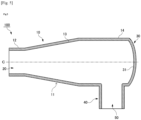
- Fig. 1 to Fig. 3 illustrate one embodiment of an inhalation aid 100 according to the present invention.
- Fig. 1 is a perspective view illustrating an overall configuration of the inhalation aid 100
- Fig. 2 is a cross-sectional view in a longitudinal direction
- Fig. 3 is a cross-sectional view in a lateral direction.
- the inhalation aid 100 is configured as a tubular shape with a closed bottom in which an introduction port 20 is disposed at one end of the cylindrical main body part 10 and a wall surface part 30 is disposed at another end side of the main body part 10.
- a side surface 11 is formed from one end to the other end of the main body part 10, and a mouthpiece 50 having an inhalation port 40 is disposed on the side surface 11 near the wall surface part 30.
- the internal space of the main body part 10 communicates with the introduction port 20 and the inhalation port 40 of the mouthpiece 50. Therefore, a patient can inhale drug particles introduced from the introduction port 20 to inside of the main body part 10 by breathing while holding the mouthpiece 50 in the mouth.
- MDI Metered-Dose Inhaler
- Adoair registered trademark
- Aerosol registered trademark
- Flutiform registered trademark
- the inhalation aid 100 may be either a reusable type or a disposable type.
- a material that constitutes the inhalation aid 100 is not particularly limited, and as a reusable type, it may be made of plastic, carbon, or metal, and as a disposable type, it may be made of paper or wood. Since the inhalation aid 100 of the present invention is structurally simple, it can be easily washed and has excellent maintainability. Moreover, since its manufacturing cost can be kept at a low price, both a reusable type and a disposable type can be preferably used.
- the main body part 10 can be separated into a side parallel part of introduction port 12, a reverse-tapered part 13, and a side parallel part of wall surface port 14. That is, inner surfaces of the side surface 11 of the main body part 10 in the side parallel part of introduction port 12 and the side parallel part of wall surface port 14 are parallelly formed, viewed from a cross-sectional surface, and the reverse-tapered part 13 is positioned between these parallel parts 12, 14. However, when comparing an inner diameter a (diameter) of the side parallel part of introduction port 12 and an inner diameter b (diameter) of the side parallel part of wall surface port 14, the inner diameter b is formed larger ( a ⁇ b ). Therefore, the reverse-tapered part 13 positioned between the parallel parts 12, 14 is configured to have a predetermined length l such that an inner diameter of the side surface 11 radially expands gradually from the side parallel part of introduction port 12 toward the side parallel part of wall surface port 14.
- an inclination of the inner surface of the side surface 11 constituting the reverse-tapered part 13 is indicated by reference numeral ⁇ .
- the inclination ⁇ referred to here is a half value of a taper angle.
- the inclination ⁇ [%] of the side surface 11 constituting the reverse-tapered part 13 can be obtained by a formula: ( b - a )/l ⁇ 0.5.
- the inner diameter a of the side parallel part of introduction port 12 is preferred to be 30 to 35 mm such that the spout port of the MDI can be appropriately attached.
- the inner diameter b of the side parallel part of wall surface port 14 is preferred to be 45 to 50 mm so as to ensure enough space for the drug particles to spread efficiently.
- the length l of the reverse-tapered part 13 is preferred to be 80 to 180 mm so as to ensure enough time and length for the drug particles introduced from the introduction port 20 to spread.
- the inclination ⁇ [degree] of the inner surface of the side surface 11 constituting the reverse-tapered part 13 is preferred to be in a range of 5 to 15 degrees.
- the wall surface part 30 is disposed in a position opposed to the introduction port 20.
- a center line C that passes through the center of the introduction port 20 and extends along the longitudinal direction of the main body part 10 is illustrated, and the wall surface part 30 is arranged in a position intersecting with the center line C.
- the wall surface part 30 is preferred to be perpendicular to the center line C of the introduction port 20. Accordingly, it is considered that at least a part of the drug particles dispersed from the introduction port 20 toward the main body part 10 collide with the wall surface part 30 and are reflected in the internal space side of the main body part 10. Further, in a case where the main body part 10 has a cylindrical shape, the wall surface part 30 becomes to have a circular shape. In particular, the main body part 10 and the wall surface part 30 are configured in a concentric circle.
- the mouthpiece 50 having the inhalation port 40 is formed in the side surface 11 of the main body part 10.
- the mouthpiece 50 is preferred to have a shape that is easy to be held in the mouth, such as an ellipse, a perfect circle, or the like.
- the mouthpiece 50 is preferred to be disposed in the side parallel part of wall surface port 14 of the main body part 10, and especially preferred to be disposed along an extended line of the wall surface part 30. Further, as shown in Fig. 2 , a level difference and the like are preferred not to exist in the internal space between the wall surface part 30 and the mouthpiece 50.
- the inhalation port 40 of the mouthpiece 50 is preferred to be perpendicular to the internal space of the main body part 10.
- Fig. 2 illustrates the center line O that passes through the center of the inhalation port 40 and extends along the mouthpiece 50, and this center line O of the inhalation port 40 is preferred to be perpendicular to the above-described center line C of the introduction port 20.
- the center line O of the inhalation port 40 is preferred to extend in parallel with the wall surface part 30. Note that, the center line O of the inhalation port 40 and the center line C of the introduction port 20 are not necessarily required to be perpendicular to one another in the present invention, and may be an angle designed arbitrarily.
- the corner made by the center lines O, C is preferred to have an angle of 60 to 120 degrees, and is particularly preferred to have an angle of 80 to 100 degrees.
- the center line C and the wall surface part 30 also need not be perpendicular to one another. In this case, maintaining a parallel relationship between the center line O and the wall surface part 30 is prioritized, and the corner made by the center line C and the wall surface part 30 can have an angle in a range of 80 to 100 degrees.
- the inhalation port 40 of the mouthpiece 50 is preferred to extend along the tangential direction of the main body part 10. That is, in Fig. 3 , a radial direction of an inner circumference of the cylindrical main body part 10 is indicated by the radial direction R, the center line O of the inhalation port 40 of the mouthpiece 50 does not coincide with the radial direction R of the main body part 10. Note that, while the center line O of the inhalation port 40 becomes parallel with respect to one of straight lines extending in the radial direction R of the main body part 10, the center line O of the inhalation port 40 is shifted to one side of the straight line extending in the radial direction R and does not overlap with the line.
- the tangential direction of the inner circumference of the cylindrical main body part 10 is indicated by reference numeral T.
- the tangent line T of the inner circumference is a straight line in parallel with respect to the radial direction R extending along a certain radial direction of the inner circumference. Note that, the tangent line T of the inner circumference and the radial direction R extending along the radial direction do not overlap, and these two straight lines are always a constant distance apart.
- the center line O of the inhalation port 40 of the mouthpiece 50 extends in parallel with the tangential direction T of the main body part 10.
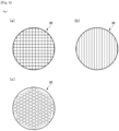
- Fig. 4 illustrates an example of a rectification structure of an inner surface 31 of the wall surface part 30.
- a plurality of linear or dot shaped protrusions or recesses are disposed in the inner surface 31 of the wall surface part 30.
- a plurality of linear protrusions (ridges) or recesses (grooves) are formed in a grid form (mesh form). That is, in the grid pattern indicated in Fig. 4(a) , a plurality of linear protrusions or recesses extending in one direction and a plurality of linear protrusions or recesses extending in a direction intersecting therewith are formed.
- a plurality of linear protrusions or recesses are formed in a stripe form. That is, in the stripe pattern indicated in Fig. 4(b) , a plurality of linear protrusions or recesses extend in parallel only in one direction. Further, in the example indicated in Fig. 4(c) , a plurality of dot-shaped protrusions or recesses are arranged at predetermined intervals. Respective sizes of the protrusions or recesses and the intervals (pitches) of the protrusions or recesses can be appropriately adjusted according to characteristics of the drug particle dispersed airflow, the particle diameter of the drugs introduced into the main body part 10, and the like.
- the wall surface part 30 is disposed in a position opposed to the introduction port 20, and the rectification structure as indicated in Fig. 4 is applicable to the inner surface 31 of this wall surface part 30.
- Fig. 5 illustrates an example of a focalization structure of the inner surface 31 of the wall surface part 30.
- the inner surface 31 of the wall surface part 30 can be a surface recessed as a recessed surface.
- the wall surface part 30 is configured as a circular shape, and the inner surface 31 of the wall surface part 30 similarly becomes a surface recessed in a hemispherical shape.
- the deepest portion of the recessed surface of the wall surface part 30 is preferred to be positioned on the extended line of the center line C of the introduction port 20.
- the drug particles that have collided with the wall surface part 30 are inversed toward the center of the main body part 10.
- the drug particles advance toward the wall surface part 30 while radially spreading.
- the drug particles that are reflected by the wall surface part 30 are redispersed in a direction colliding with the side surface 11 of the main body part 10.
- focalizing the flow of the drug particles by forming the wall surface part 30 as a recessed surface, it is possible to suppress the drug particles reflected by the wall surface part 30 being trapped on the inner surface of the side surface 11.
- the rectification structure illustrated in Fig. 4 and the focalization structure illustrated in Fig. 5 can be used together. That is, the inner surface 31 of the wall surface part 30 may be molded as a recessed surface (especially a concave surface), and a plurality of protrusions or recesses can be formed on that recessed surface.
- the inner surface 31 of the wall surface part 30 can also be bulged as a convex surface in opposed to the example indicated in Fig. 5 . Although this case is not preferrable since it allows the drug particles reflected by the inner surface 31 of the wall surface part 30 to easily collide with the side surface 11 of the main body part 10. If a certain meaning is found in forming the inner surface 31 of the wall surface part 30 as a convex surface, it may be configured as such.
Landscapes
- Health & Medical Sciences (AREA)
- Engineering & Computer Science (AREA)
- Life Sciences & Earth Sciences (AREA)
- Animal Behavior & Ethology (AREA)
- Anesthesiology (AREA)
- Biomedical Technology (AREA)
- Heart & Thoracic Surgery (AREA)
- Hematology (AREA)
- Veterinary Medicine (AREA)
- Public Health (AREA)
- General Health & Medical Sciences (AREA)
- Dispersion Chemistry (AREA)
- Chemical & Material Sciences (AREA)
- Bioinformatics & Cheminformatics (AREA)
- Pulmonology (AREA)
- Medicinal Preparation (AREA)
- Containers And Packaging Bodies Having A Special Means To Remove Contents (AREA)
- Media Introduction/Drainage Providing Device (AREA)
Abstract
Description
- The present invention relates to an inhalation aid mounted on a spout port of an atomization type inhaler for assisting inhalation of dispersed drugs.
- As treatment for bronchial asthma and chronic obstructive pulmonary disease (COPD), which are respiratory tract diseases, suction therapy is one of the most effective treatment methods. In the current suction therapy, a Dry Powder Inhaler (DPI) and a Metered-Dose Inhaler (MDI) are generally used for inhaling particulate drugs including, for example, an inhaled corticosteroid, a long-acting β2 agonist, and a long-acting muscarinic antagonist.
- Of these, the Metered-Dose Inhaler (MDI) is a type of inhaler for atomizing constant amounts of drug particles using gas pressure. As a patient inhales the drug particles dispersed from the atomization type inhaler, the drug particles get transported to the human respiratory tract through the respiratory organs. However, such atomization type inhaler requires matching the timings of the drug atomization and the patient inhalation. Therefore, in a case where the timing of the drug atomization is difficult to take, such as when the patient is an infant or an old person, an inhalation aid is sometimes attached to a spout port of the atomization type inhaler in order to further ensure patient inhalation of the drug particles. As the inhalation aid (also referred to as an inhalation spacer), ones disclosed in PLT 1 and PLT 2 are known as examples.
- Patent Document 1:
JP-A-8-266626 - Patent Document 2:
JP-T-2008-516658 - PLT 1 discloses a device that performs vaporization and dispersion of aerosol droplets for drug inhalation therapy. The device includes a main body having rotational symmetry, a tubular member arranged on one of front ends and protruding by a defined length into the main body, and an intake air member through which ambient air can flow into the main body when a patient inhales the aerosol stored in the main body via the other tubular member. With such configuration, it is considered that, since two spiral turbulences are formed one inside and the other outside in the main body, the outer one of the turbulences avoids an impaction of the drug particles against the inside wall of the vessel. However, in the device in PLT 1, an introduction port of the drug particles dispersed from the atomization type inhaler and an inhalation port for inhaling the drug particles are disposed in a straight line. Although the device in PLT 1 allows shifting the timing of dispersion by the atomization type inhaler from the inhalation timing just as much as the length of the main body, a large amount of the drug particles dispersed into the main body through the introduction port directly heads to the inhalation port. Therefore, the drug particles are required to be inhaled immediately after the drug particles are dispersed into the main body by the atomization type inhaler, and the timing adjustment effect is not in sufficient. Accordingly, a patient with poor inhalation ability may possibly still find it difficult to inhale the drug particles.
- Further, PLT 2 discloses a device that is a spacer device for oral administration of a volatile medium containing drug particles. The spacer device includes a chamber having an introduction port, an outlet to be received in the mouth, and a butterfly valve. By thus providing a valve structure in the spacer, a patient can inhale the drug particles dispersed into a main body from an atomization type inhaler at an arbitrary timing, which makes it possible even for a patient with poor inhalation ability to inhale the drug particles relatively easily. However, since the whole structure of the spacer becomes complicated by providing the valve structure in the spacer, in a case where the spacer is a reusable type, there is a problem that disassembly, cleaning, and assembly of the spacer become difficult. In addition, in a case where the spacer is a disposable type, there is a problem that providing the valve structure raises manufacturing cost of the spacer and increases financial burden of the patient who uses the spacer.
- Therefore, a main object of the present invention is to provide an inhalation aid that allows a patient to arbitrarily adjust a drug atomization timing with ease without relying on a valve structure.
- The present invention relates to an
inhalation aid 100 for being mounted on a spout port of an atomization type inhaler. Theinhalation aid 100 according to the present invention is applicable to a general Metered-Dose Inhaler (MDI). Theinhalation aid 100 of the present invention includes amain body part 10, anintroduction port 20, awall surface part 30, and aninhalation port 40. Themain body part 10 has a tubular structure, and drug particles are dispersed into an internal space of themain body part 10 from the atomization type inhaler. Themain body part 10 is preferred to have a reverse-tapered shape like as circular-truncated cone shape but may be any other polygonal shape including a triangular tubular shape, a rectangular tubular shape, or a pentagonal tubular shape. Theintroduction port 20 is an opening portion for introducing the drug particles dispersed from the spout port of the inhaler into themain body part 10, and is disposed on one end side of themain body part 10. Thewall surface part 30 is disposed in a position on another end side of themain body part 10 opposed to theintroduction port 20. Therefore, themain body part 10 has a tubular structure with a closed bottom in which theintroduction port 20 is disposed on the one end side, and thewall surface part 30 is disposed on the other end side. Theintroduction port 20 and thewall surface part 30 are disposed in a straight line. Theinhalation port 40 is an opening portion for inhaling the drug particles introduced into themain body part 10, and is disposed on aside surface 11 of themain body part 10. - As in the above-described configuration, by providing the
wall surface part 30 in a position opposed to theintroduction port 20 and providing theinhalation port 40 in a position not coaxial with theintroduction port 20, dispersed airflows collide with one another, which make it difficult for the drug particles to be introduced from theintroduction port 20 to directly reach theinhalation port 40. Therefore, without providing a valve mechanism like the conventional spacer, a patient can arbitrarily adjust the drug inhalation timing with more ease. In addition, a patient who has difficulty inhaling the whole amounts of drugs at once can divide the drugs introduced in themain body part 10 and inhale it over multiple times. To explain more specifically, among the drug particles dispersed into themain body part 10, the drug particles that did not collide with theside surface 11 or thewall surface part 30 of themain body part 10 and are not trapped or accumulated in those areas remain in themain body part 10 for a while after being atomized. These drug particles that remain and are dispersed in the gas phase are transported from theinhalation port 40 installed in a side surface direction perpendicular to the center axis of theintroduction port 20 to the human respiratory tract through the respiratory organs by multiple times of oral inhalation. Thus, in the present invention, causes of collision, accumulation, entrapment, and the like into the inner surface of themain body part 10 at the time of atomizing can be eliminated by the drug inhaled structure that is different from the conventional technique. In other words, while the conventional technique allows accumulation/entrapment rate due to collision to be changed by influence of inhalation conditions (such as a respiratory rate or a tidal volume) at the time of inhalation, in the present invention, the drug atomization rate does not receive strong influence of the inhalation conditions even in normal breathing. - Especially, in the
inhalation aid 100 according to the present invention, theinhalation port 40 is preferred to extend along a tangential direction of themain body part 10. That is, in a case where themain body part 10 is formed as a cylindrical shape, when viewed from thewall surface part 30 side (or theintroduction port 20 side) of theinhalation aid 100, theinhalation port 40 does not extend along a radial direction of themain body part 10, and instead, extends along the tangential direction of the cylindricalmain body part 10. By thus forming theinhalation port 40 in a shifted position with respect to the radial direction of themain body part 10, when the drug particles in themain body part 10 are inhaled via theinhalation port 40, a spiral airflow can be generated in the main body part 10 (seeFig. 3 ). Accordingly, an inhalation efficiency of the drug particles dispersed into themain body part 10 can be improved. - In the
inhalation aid 100 according to the present invention, theinhalation port 40 is preferred to be disposed approximately on an extended line of thewall surface part 30. In the present invention, while theinhalation port 40 can be disposed on theside surface 11 of themain body part 10 between theintroduction port 20 and thewall surface part 30, it is especially preferred to be disposed in a position near thewall surface part 30, particularly on the extended line of thewall surface part 30. With such configuration, the drug particles dispersed from theintroduction port 20 toward thewall surface part 30 can be efficiently inhaled. - In the
inhalation aid 100 according to the present invention, the inner surface inside themain body part 10 of thewall surface part 30 may be formed as a recessed surface. By thus forming the inner surface of thewall surface part 30 as a recessed surface (especially a concave surface), the flow of the drug particles inversing on thewall surface part 30 can be focalized in the center axis direction. Accordingly, the drug particles become less likely to be trapped or accumulated in the inner surface of themain body part 10 and, as a result, the drug inhalation rate improves. That is, while drug particles are dispersed radially, in a straight line, and intermittently from the atomization type inhaler into themain body part 10 of theinhalation aid 100, which causes the drug particles to collide with theside surface 11 and thewall surface part 30 inside themain body part 10, and at least part of the drug particles to be accumulated or trapped in those areas, the present invention proposes a method for reducing such accumulation and entrapment of the drug particles. - In the
inhalation aid 100 according to the present invention, one or a plurality of protrusions or recesses may be formed on the inner surface inside themain body part 10 of thewall surface part 30. The protrusions or recesses include dot shaped ones and linear ones. (Linear-shaped protrusions or recesses are also referred to as having a ridge shape or a groove shape.) The drug particles dispersed into themain body part 10 of theinhalation aid 100 repel and/or collide, or become accumulated or trapped at boundary layers of theside surface 11 and thewall surface part 30 after being atomized, and especially, a complicated turbulent flow is formed inside themain body part 10 by collision and merging of the flow of the drug particles that have repelled in thewall surface part 30 and the flow of the subsequently dispersed drug particles. In this respect, the flow of the drug particles can be rectified by forming, for example, a mesh structure with a plurality of protrusions or recesses on the inner surface of thewall surface part 30. Further, in order to suppress the turbulent flow of the drug particles, it is preferred to form a plurality of protrusions or recesses on the inner surface of thewall surface part 30 to rectify the flow and also, as described above, form the inner surface of thewall surface part 30 as a recessed surface to focalize the inversed flow of the drug particles in the center axis direction. - In the
inhalation aid 100 according to the present invention, the side surface 11 (especially the inner surface of the side surface 11) of themain body part 10 is preferred to be at least partly formed in a reverse-tapered shape having a diameter that expands from one end side toward another end side. The drug particles dispersed into themain body part 10 are dispersed in themain body part 10 while radially expanding, but by forming theside surface 11 of themain body part 10 as a reverse-tapered shape, an atomization flow of the drug particles in the direction of themain body part 10 becomes reduced and allows suppressing the drug particles being attached to or trapped on theside surface 11. - The present invention can provide an inhalation aid with which a patient may arbitrarily adjust a drug inhalation timing with ease without relying on a valve structure.
-
-
Fig. 1 is a perspective view illustrating one embodiment of an inhalation aid. -
Fig. 2 is a cross-sectional view schematically illustrating a vertical cross-sectional surface of the inhalation aid. -
Fig. 3 is a cross-sectional view schematically illustrating a lateral cross-sectional surface of the inhalation aid. -
Fig. 4 illustrates an example of a rectification structure on an inner surface of a wall surface part. -
Fig. 5 illustrates an example of a focalization structure on the inner surface of the wall surface part - The following describes embodiments to embody the present invention using the drawings. The present invention is not limited to the embodiments described below, but includes those appropriately modified from the embodiments below by a person skilled in the art within an obvious range.
-
Fig. 1 to Fig. 3 illustrate one embodiment of aninhalation aid 100 according to the present invention.Fig. 1 is a perspective view illustrating an overall configuration of theinhalation aid 100,Fig. 2 is a cross-sectional view in a longitudinal direction, andFig. 3 is a cross-sectional view in a lateral direction. As shown in these drawings, theinhalation aid 100 is configured as a tubular shape with a closed bottom in which anintroduction port 20 is disposed at one end of the cylindricalmain body part 10 and awall surface part 30 is disposed at another end side of themain body part 10. Aside surface 11 is formed from one end to the other end of themain body part 10, and amouthpiece 50 having aninhalation port 40 is disposed on theside surface 11 near thewall surface part 30. The internal space of themain body part 10 communicates with theintroduction port 20 and theinhalation port 40 of themouthpiece 50. Therefore, a patient can inhale drug particles introduced from theintroduction port 20 to inside of themain body part 10 by breathing while holding themouthpiece 50 in the mouth. - As the
introduction port 20 of theinhalation aid 100, a spout port of a publicly known Metered-Dose Inhaler (MDI) can be attached. Examples of the currently publicly known MDIs include Adoair (registered trademark) Aerosol and Flutiform (registered trademark), but MDIs applicable to the present invention are not limited to these. - The
inhalation aid 100 may be either a reusable type or a disposable type. A material that constitutes theinhalation aid 100 is not particularly limited, and as a reusable type, it may be made of plastic, carbon, or metal, and as a disposable type, it may be made of paper or wood. Since theinhalation aid 100 of the present invention is structurally simple, it can be easily washed and has excellent maintainability. Moreover, since its manufacturing cost can be kept at a low price, both a reusable type and a disposable type can be preferably used. - As shown in
Fig. 1 andFig. 2 , themain body part 10 can be separated into a side parallel part ofintroduction port 12, a reverse-taperedpart 13, and a side parallel part ofwall surface port 14. That is, inner surfaces of theside surface 11 of themain body part 10 in the side parallel part ofintroduction port 12 and the side parallel part ofwall surface port 14 are parallelly formed, viewed from a cross-sectional surface, and the reverse-taperedpart 13 is positioned between theseparallel parts introduction port 12 and an inner diameter b (diameter) of the side parallel part ofwall surface port 14, the inner diameter b is formed larger ( a < b ). Therefore, the reverse-taperedpart 13 positioned between theparallel parts side surface 11 radially expands gradually from the side parallel part ofintroduction port 12 toward the side parallel part ofwall surface port 14. - In
Fig. 2 , an inclination of the inner surface of theside surface 11 constituting the reverse-taperedpart 13 is indicated by reference numeral θ. The inclination θ referred to here is a half value of a taper angle. The inclination θ [%] of theside surface 11 constituting the reverse-taperedpart 13 can be obtained by a formula: ( b - a )/l × 0.5. Specifically, the inner diameter a of the side parallel part ofintroduction port 12 is preferred to be 30 to 35 mm such that the spout port of the MDI can be appropriately attached. Further, the inner diameter b of the side parallel part ofwall surface port 14 is preferred to be 45 to 50 mm so as to ensure enough space for the drug particles to spread efficiently. Further, the length l of the reverse-taperedpart 13 is preferred to be 80 to 180 mm so as to ensure enough time and length for the drug particles introduced from theintroduction port 20 to spread. As a result, the inclination θ [degree] of the inner surface of theside surface 11 constituting the reverse-taperedpart 13 is preferred to be in a range of 5 to 15 degrees. - As shown in
Fig. 2 , in theinhalation aid 100, thewall surface part 30 is disposed in a position opposed to theintroduction port 20. Specifically, inFig. 2 , a center line C that passes through the center of theintroduction port 20 and extends along the longitudinal direction of themain body part 10 is illustrated, and thewall surface part 30 is arranged in a position intersecting with the center line C. In particular, thewall surface part 30 is preferred to be perpendicular to the center line C of theintroduction port 20. Accordingly, it is considered that at least a part of the drug particles dispersed from theintroduction port 20 toward themain body part 10 collide with thewall surface part 30 and are reflected in the internal space side of themain body part 10. Further, in a case where themain body part 10 has a cylindrical shape, thewall surface part 30 becomes to have a circular shape. In particular, themain body part 10 and thewall surface part 30 are configured in a concentric circle. - As shown in
Fig. 1 to Fig. 3 , themouthpiece 50 having theinhalation port 40 is formed in theside surface 11 of themain body part 10. Themouthpiece 50 is preferred to have a shape that is easy to be held in the mouth, such as an ellipse, a perfect circle, or the like. Themouthpiece 50 is preferred to be disposed in the side parallel part ofwall surface port 14 of themain body part 10, and especially preferred to be disposed along an extended line of thewall surface part 30. Further, as shown inFig. 2 , a level difference and the like are preferred not to exist in the internal space between thewall surface part 30 and themouthpiece 50. This allows the flow of the drug particles near thewall surface part 30 to smoothly reach the outlet of theinhalation port 40 at the time of inhalation. If a level difference exists in the internal space inside themain body part 10, the drug particles may possibly remain or get stuck in that part, and thus, such level difference should be avoided as much as possible. However, there is no problem even if a level difference and the like exists in the internal space between thewall surface part 30 and themouthpiece 50 as long as the flow of the drug particles are directed toward theinhalation port 40. For example, a level difference of around 5 to 15 mm is acceptable. - Further, the
inhalation port 40 of themouthpiece 50 is preferred to be perpendicular to the internal space of themain body part 10. Specifically,Fig. 2 illustrates the center line O that passes through the center of theinhalation port 40 and extends along themouthpiece 50, and this center line O of theinhalation port 40 is preferred to be perpendicular to the above-described center line C of theintroduction port 20. Further, the center line O of theinhalation port 40 is preferred to extend in parallel with thewall surface part 30. Note that, the center line O of theinhalation port 40 and the center line C of theintroduction port 20 are not necessarily required to be perpendicular to one another in the present invention, and may be an angle designed arbitrarily. For example, the corner made by the center lines O, C is preferred to have an angle of 60 to 120 degrees, and is particularly preferred to have an angle of 80 to 100 degrees. Further, in a case where the center lines O, C are not perpendicular to one another, the center line C and thewall surface part 30 also need not be perpendicular to one another. In this case, maintaining a parallel relationship between the center line O and thewall surface part 30 is prioritized, and the corner made by the center line C and thewall surface part 30 can have an angle in a range of 80 to 100 degrees. - Further, as shown in
Fig. 3 , theinhalation port 40 of themouthpiece 50 is preferred to extend along the tangential direction of themain body part 10. That is, inFig. 3 , a radial direction of an inner circumference of the cylindricalmain body part 10 is indicated by the radial direction R, the center line O of theinhalation port 40 of themouthpiece 50 does not coincide with the radial direction R of themain body part 10. Note that, while the center line O of theinhalation port 40 becomes parallel with respect to one of straight lines extending in the radial direction R of themain body part 10, the center line O of theinhalation port 40 is shifted to one side of the straight line extending in the radial direction R and does not overlap with the line. On the other hand, inFig. 3 , the tangential direction of the inner circumference of the cylindricalmain body part 10 is indicated by reference numeral T. The tangent line T of the inner circumference is a straight line in parallel with respect to the radial direction R extending along a certain radial direction of the inner circumference. Note that, the tangent line T of the inner circumference and the radial direction R extending along the radial direction do not overlap, and these two straight lines are always a constant distance apart. In this case, the center line O of theinhalation port 40 of themouthpiece 50 extends in parallel with the tangential direction T of themain body part 10. By thus shifting theinhalation port 40, the spiral flow as indicated inFig. 3 can be generated in the internal space of themain body part 10 at the time of inhalation. As a result, the inhalation efficiency of the drugs can be improved. -
Fig. 4 illustrates an example of a rectification structure of aninner surface 31 of thewall surface part 30. In this rectification structure, a plurality of linear or dot shaped protrusions or recesses are disposed in theinner surface 31 of thewall surface part 30. In the example indicated inFig. 4(a) , a plurality of linear protrusions (ridges) or recesses (grooves) are formed in a grid form (mesh form). That is, in the grid pattern indicated inFig. 4(a) , a plurality of linear protrusions or recesses extending in one direction and a plurality of linear protrusions or recesses extending in a direction intersecting therewith are formed. On the other hand, in the example shown inFig. 4(b) , a plurality of linear protrusions or recesses are formed in a stripe form. That is, in the stripe pattern indicated inFig. 4(b) , a plurality of linear protrusions or recesses extend in parallel only in one direction. Further, in the example indicated inFig. 4(c) , a plurality of dot-shaped protrusions or recesses are arranged at predetermined intervals. Respective sizes of the protrusions or recesses and the intervals (pitches) of the protrusions or recesses can be appropriately adjusted according to characteristics of the drug particle dispersed airflow, the particle diameter of the drugs introduced into themain body part 10, and the like. As another feature of theinhalation aid 100 of the present invention, thewall surface part 30 is disposed in a position opposed to theintroduction port 20, and the rectification structure as indicated inFig. 4 is applicable to theinner surface 31 of thiswall surface part 30. -
Fig. 5 illustrates an example of a focalization structure of theinner surface 31 of thewall surface part 30. As shown inFig. 5 , theinner surface 31 of thewall surface part 30 can be a surface recessed as a recessed surface. In a case where themain body part 10 has a cylindrical shape, thewall surface part 30 is configured as a circular shape, and theinner surface 31 of thewall surface part 30 similarly becomes a surface recessed in a hemispherical shape. Especially, as indicated inFig. 5 , the deepest portion of the recessed surface of thewall surface part 30 is preferred to be positioned on the extended line of the center line C of theintroduction port 20. By thus forming theinner surface 31 of thewall surface part 30 as a recessed surface, the drug particles that have collided with thewall surface part 30 are inversed toward the center of themain body part 10. As mentioned above, when the drug particles are introduced into themain body part 10, the drug particles advance toward thewall surface part 30 while radially spreading. However, even if thewall surface part 30 remains a planar surface, the drug particles that are reflected by thewall surface part 30 are redispersed in a direction colliding with theside surface 11 of themain body part 10. Further, by focalizing the flow of the drug particles by forming thewall surface part 30 as a recessed surface, it is possible to suppress the drug particles reflected by thewall surface part 30 being trapped on the inner surface of theside surface 11. - In addition, the rectification structure illustrated in
Fig. 4 and the focalization structure illustrated inFig. 5 can be used together. That is, theinner surface 31 of thewall surface part 30 may be molded as a recessed surface (especially a concave surface), and a plurality of protrusions or recesses can be formed on that recessed surface. - Note that, the
inner surface 31 of thewall surface part 30 can also be bulged as a convex surface in opposed to the example indicated inFig. 5 . Although this case is not preferrable since it allows the drug particles reflected by theinner surface 31 of thewall surface part 30 to easily collide with theside surface 11 of themain body part 10. If a certain meaning is found in forming theinner surface 31 of thewall surface part 30 as a convex surface, it may be configured as such. - In this application, the embodiments of the present invention have been described above by referring to the drawings to express the contents of the present invention. However, the present invention is not limited to the embodiments described above, and includes changed embodiments and improved embodiments obvious to those skilled in the art based on the matters described in this application.
-
- 10
- main body part
- 11
- side surface
- 12
- side parallel part of introduction port
- 13
- reverse-tapered part
- 14
- side parallel part of wall surface port
- 20
- introduction port
- 30
- wall surface part
- 31
- inner surface
- 40
- inhalation port
- 50
- mouthpiece
- 100
- spacer
Claims (5)
- An inhalation aid for being mounted on a spout port of an atomization type inhaler, comprising:a tubular main bodyan introduction port disposed on one end side of the main body part for introducing drugs atomized from the spout port of the inhaler into the main body part;a wall surface part disposed in a position opposed to the introduction port on another end side of the main body part; andan inhalation port disposed on a side surface of the main body part for inhaling the drugs introduced into the main body part,wherein the inhalation port extends along a tangential direction of the main body part.
- The inhalation aid according to claim 1, wherein the inhalation port is disposed on an extended line of the wall surface part.
- The inhalation aid according to claim 1, wherein an inner surface inside the main body part of the wall surface part is formed as a recessed surface.
- The inhalation aid according to claim 1, wherein one or a plurality of protrusions or recesses are formed on the inner surface inside the main body part of the wall surface part.
- The inhalation aid according to claim 1, wherein the side surface of the main body part is formed at least partly in a reverse-tapered shape radially expanding from the one end side to the other end side.
Applications Claiming Priority (2)
| Application Number | Priority Date | Filing Date | Title |
|---|---|---|---|
| JP2020197374A JP6958950B1 (en) | 2020-11-27 | 2020-11-27 | Inhalation aid |
| PCT/JP2021/040885 WO2022113705A1 (en) | 2020-11-27 | 2021-11-05 | Inhalation aid |
Publications (3)
| Publication Number | Publication Date |
|---|---|
| EP4252805A1 true EP4252805A1 (en) | 2023-10-04 |
| EP4252805A4 EP4252805A4 (en) | 2024-10-02 |
| EP4252805B1 EP4252805B1 (en) | 2025-12-31 |
Family
ID=78282109
Family Applications (1)
| Application Number | Title | Priority Date | Filing Date |
|---|---|---|---|
| EP21897680.1A Active EP4252805B1 (en) | 2020-11-27 | 2021-11-05 | INHALATION AID |
Country Status (5)
| Country | Link |
|---|---|
| US (1) | US20230226286A1 (en) |
| EP (1) | EP4252805B1 (en) |
| JP (1) | JP6958950B1 (en) |
| CN (1) | CN115697445B (en) |
| WO (1) | WO2022113705A1 (en) |
Families Citing this family (1)
| Publication number | Priority date | Publication date | Assignee | Title |
|---|---|---|---|---|
| JP1700983S (en) * | 2021-06-23 | 2021-11-29 |
Family Cites Families (20)
| Publication number | Priority date | Publication date | Assignee | Title |
|---|---|---|---|---|
| GB2000555A (en) * | 1977-07-01 | 1979-01-10 | Ici Ltd | Aerosol dispensing device |
| DE3164656D1 (en) * | 1980-03-25 | 1984-08-16 | Hilal Malem | MEDICAL NEBULISING APPARATUS |
| FI89458C (en) * | 1986-11-06 | 1993-10-11 | Leiras Oy | INHALERINGSANORDNING |
| US4953545A (en) * | 1989-10-18 | 1990-09-04 | Mccarty Jerry | Disposable respiratory medication dispersion chamber |
| EP0504459B1 (en) * | 1991-03-21 | 1996-06-05 | PAUL RITZAU PARI-WERK GmbH | Nebulizer, in particular for use in inhalation therapy apparatus |
| ES2141108T3 (en) * | 1991-07-02 | 2000-03-16 | Inhale Inc | METHOD AND DEVICE FOR PROVIDING DRUGS IN AEROSOL. |
| SE9400257D0 (en) * | 1994-01-27 | 1994-01-27 | Astra Ab | spacer |
| ATE205098T1 (en) * | 1994-05-19 | 2001-09-15 | Pari Gmbh | DEVICE FOR DRYING AND BUFFERING AEROSOLS |
| CA2212430A1 (en) * | 1997-08-07 | 1999-02-07 | George Volgyesi | Inhalation device |
| US6073629A (en) * | 1997-09-25 | 2000-06-13 | Norton Healthcare Ltd. | Inhaler spacer |
| GB2344533B (en) * | 1998-12-11 | 2000-10-18 | Bespak Plc | Improvements in or relating to dispensing apparatus |
| GB2353222B (en) * | 1999-06-23 | 2001-09-19 | Cambridge Consultants | Inhalers |
| US7726302B1 (en) * | 1999-11-16 | 2010-06-01 | Helle Funch Nielsen | Inhalator for treatment of bronchial disorder in horses |
| US7204245B2 (en) * | 2000-07-06 | 2007-04-17 | Clinical Technologies, Inc | Aerosol enhancement device |
| EP2186536B1 (en) * | 2002-04-19 | 2012-03-28 | 3M Innovative Properties Company | A spacer or actuator for inertial removal of the non-respirable fraction of medicinal aerosols |
| EP1804871B1 (en) | 2004-10-15 | 2012-06-20 | Cipla Ltd. | An improved spacer |
| FR2888510B1 (en) * | 2005-07-13 | 2009-01-30 | Diffusion Tech Francaise Sarl | DEVICE FOR TRANSPORTING AEROSOLS FOR MEDICAL AEROSOL GENERATORS |
| JP5092820B2 (en) * | 2008-03-13 | 2012-12-05 | オムロンヘルスケア株式会社 | Nebulizer and inhalation aid used therefor |
| WO2009128491A1 (en) * | 2008-04-17 | 2009-10-22 | 帝人ファーマ株式会社 | Inhalation aid for metered dose inhaler spray |
| US20180236189A1 (en) * | 2017-02-17 | 2018-08-23 | Shawky Hassan | Metered dose inhaler and spacer with airflow and handicap assist structures for maximizing medication delivery effectiveness |
-
2020
- 2020-11-27 JP JP2020197374A patent/JP6958950B1/en active Active
-
2021
- 2021-11-05 WO PCT/JP2021/040885 patent/WO2022113705A1/en not_active Ceased
- 2021-11-05 EP EP21897680.1A patent/EP4252805B1/en active Active
- 2021-11-05 US US17/928,622 patent/US20230226286A1/en active Pending
- 2021-11-05 CN CN202180037899.2A patent/CN115697445B/en active Active
Also Published As
| Publication number | Publication date |
|---|---|
| EP4252805A4 (en) | 2024-10-02 |
| WO2022113705A1 (en) | 2022-06-02 |
| JP2022085607A (en) | 2022-06-08 |
| CN115697445A (en) | 2023-02-03 |
| US20230226286A1 (en) | 2023-07-20 |
| EP4252805B1 (en) | 2025-12-31 |
| CA3184771A1 (en) | 2022-06-02 |
| JP6958950B1 (en) | 2021-11-02 |
| CN115697445B (en) | 2025-09-23 |
Similar Documents
| Publication | Publication Date | Title |
|---|---|---|
| US6073629A (en) | Inhaler spacer | |
| EP1392382B1 (en) | Inhaler | |
| CN101977647B (en) | Inhaler | |
| KR100906269B1 (en) | Dry powder inhaler | |
| AU750459B2 (en) | Method and apparatus for delivering aerosolized medication | |
| JP3014405B2 (en) | Auxiliary device for aerosol inhaler | |
| JP5647736B2 (en) | Spacers and components therefor | |
| US5477849A (en) | Spacer for medication inhaler | |
| CA2972826C (en) | Powder dispersion methods and devices | |
| KR100366323B1 (en) | Pediatric suction chamber for use in combination with metered dose inhalers | |
| US20120318261A1 (en) | Valved Holding Chamber With Whistle for the Administration of Inhalable Drugs | |
| JP2005506855A (en) | Inhaler | |
| US10682476B2 (en) | Powder inhaler, system and methods | |
| EP4252805B1 (en) | INHALATION AID | |
| EP1019126B9 (en) | Inhaler spacer | |
| CA3184771C (en) | Inhalation aid | |
| EP3463528A1 (en) | Inhaler spacer | |
| AU776816B2 (en) | Method and apparatus for delivering aerosolized medication | |
| JPH0822314B2 (en) | Inhaler for aerosol drugs | |
| HK1149517B (en) | Inhaler |
Legal Events
| Date | Code | Title | Description |
|---|---|---|---|
| STAA | Information on the status of an ep patent application or granted ep patent |
Free format text: STATUS: THE INTERNATIONAL PUBLICATION HAS BEEN MADE |
|
| PUAI | Public reference made under article 153(3) epc to a published international application that has entered the european phase |
Free format text: ORIGINAL CODE: 0009012 |
|
| STAA | Information on the status of an ep patent application or granted ep patent |
Free format text: STATUS: REQUEST FOR EXAMINATION WAS MADE |
|
| 17P | Request for examination filed |
Effective date: 20221114 |
|
| AK | Designated contracting states |
Kind code of ref document: A1 Designated state(s): AL AT BE BG CH CY CZ DE DK EE ES FI FR GB GR HR HU IE IS IT LI LT LU LV MC MK MT NL NO PL PT RO RS SE SI SK SM TR |
|
| DAV | Request for validation of the european patent (deleted) | ||
| DAX | Request for extension of the european patent (deleted) | ||
| A4 | Supplementary search report drawn up and despatched |
Effective date: 20240903 |
|
| RIC1 | Information provided on ipc code assigned before grant |
Ipc: A61M 11/00 20060101ALI20240828BHEP Ipc: A61M 15/00 20060101AFI20240828BHEP |
|
| GRAP | Despatch of communication of intention to grant a patent |
Free format text: ORIGINAL CODE: EPIDOSNIGR1 |
|
| STAA | Information on the status of an ep patent application or granted ep patent |
Free format text: STATUS: GRANT OF PATENT IS INTENDED |
|
| INTG | Intention to grant announced |
Effective date: 20250630 |
|
| GRAJ | Information related to disapproval of communication of intention to grant by the applicant or resumption of examination proceedings by the epo deleted |
Free format text: ORIGINAL CODE: EPIDOSDIGR1 |
|
| STAA | Information on the status of an ep patent application or granted ep patent |
Free format text: STATUS: REQUEST FOR EXAMINATION WAS MADE |
|
| GRAS | Grant fee paid |
Free format text: ORIGINAL CODE: EPIDOSNIGR3 |
|
| STAA | Information on the status of an ep patent application or granted ep patent |
Free format text: STATUS: GRANT OF PATENT IS INTENDED |
|
| GRAP | Despatch of communication of intention to grant a patent |
Free format text: ORIGINAL CODE: EPIDOSNIGR1 |
|
| INTC | Intention to grant announced (deleted) | ||
| GRAA | (expected) grant |
Free format text: ORIGINAL CODE: 0009210 |
|
| STAA | Information on the status of an ep patent application or granted ep patent |
Free format text: STATUS: THE PATENT HAS BEEN GRANTED |
|
| INTG | Intention to grant announced |
Effective date: 20251107 |
|
| AK | Designated contracting states |
Kind code of ref document: B1 Designated state(s): AL AT BE BG CH CY CZ DE DK EE ES FI FR GB GR HR HU IE IS IT LI LT LU LV MC MK MT NL NO PL PT RO RS SE SI SK SM TR |
|
| REG | Reference to a national code |
Ref country code: CH Ref legal event code: F10 Free format text: ST27 STATUS EVENT CODE: U-0-0-F10-F00 (AS PROVIDED BY THE NATIONAL OFFICE) Effective date: 20251231 Ref country code: GB Ref legal event code: FG4D |
|
| REG | Reference to a national code |
Ref country code: DE Ref legal event code: R096 Ref document number: 602021045748 Country of ref document: DE |
|
| REG | Reference to a national code |
Ref country code: IE Ref legal event code: FG4D |
|
| REG | Reference to a national code |
Ref country code: LT Ref legal event code: MG9D |
|
| PG25 | Lapsed in a contracting state [announced via postgrant information from national office to epo] |
Ref country code: NO Free format text: LAPSE BECAUSE OF FAILURE TO SUBMIT A TRANSLATION OF THE DESCRIPTION OR TO PAY THE FEE WITHIN THE PRESCRIBED TIME-LIMIT Effective date: 20260331 |
|
| PG25 | Lapsed in a contracting state [announced via postgrant information from national office to epo] |
Ref country code: FI Free format text: LAPSE BECAUSE OF FAILURE TO SUBMIT A TRANSLATION OF THE DESCRIPTION OR TO PAY THE FEE WITHIN THE PRESCRIBED TIME-LIMIT Effective date: 20251231 Ref country code: HR Free format text: LAPSE BECAUSE OF FAILURE TO SUBMIT A TRANSLATION OF THE DESCRIPTION OR TO PAY THE FEE WITHIN THE PRESCRIBED TIME-LIMIT Effective date: 20251231 |
|
| PG25 | Lapsed in a contracting state [announced via postgrant information from national office to epo] |
Ref country code: RS Free format text: LAPSE BECAUSE OF FAILURE TO SUBMIT A TRANSLATION OF THE DESCRIPTION OR TO PAY THE FEE WITHIN THE PRESCRIBED TIME-LIMIT Effective date: 20260331 |
|
| PG25 | Lapsed in a contracting state [announced via postgrant information from national office to epo] |
Ref country code: LV Free format text: LAPSE BECAUSE OF FAILURE TO SUBMIT A TRANSLATION OF THE DESCRIPTION OR TO PAY THE FEE WITHIN THE PRESCRIBED TIME-LIMIT Effective date: 20251231 |
|
| PG25 | Lapsed in a contracting state [announced via postgrant information from national office to epo] |
Ref country code: BG Free format text: LAPSE BECAUSE OF FAILURE TO SUBMIT A TRANSLATION OF THE DESCRIPTION OR TO PAY THE FEE WITHIN THE PRESCRIBED TIME-LIMIT Effective date: 20251231 |
|
| REG | Reference to a national code |
Ref country code: NL Ref legal event code: MP Effective date: 20251231 |
|
| REG | Reference to a national code |
Ref country code: AT Ref legal event code: MK05 Ref document number: 1872531 Country of ref document: AT Kind code of ref document: T Effective date: 20251231 |
|
| PG25 | Lapsed in a contracting state [announced via postgrant information from national office to epo] |
Ref country code: NL Free format text: LAPSE BECAUSE OF FAILURE TO SUBMIT A TRANSLATION OF THE DESCRIPTION OR TO PAY THE FEE WITHIN THE PRESCRIBED TIME-LIMIT Effective date: 20251231 |
|
| PG25 | Lapsed in a contracting state [announced via postgrant information from national office to epo] |
Ref country code: LT Free format text: LAPSE BECAUSE OF FAILURE TO SUBMIT A TRANSLATION OF THE DESCRIPTION OR TO PAY THE FEE WITHIN THE PRESCRIBED TIME-LIMIT Effective date: 20251231 |
|
| PG25 | Lapsed in a contracting state [announced via postgrant information from national office to epo] |
Ref country code: SM Free format text: LAPSE BECAUSE OF FAILURE TO SUBMIT A TRANSLATION OF THE DESCRIPTION OR TO PAY THE FEE WITHIN THE PRESCRIBED TIME-LIMIT Effective date: 20251231 |
|
| PG25 | Lapsed in a contracting state [announced via postgrant information from national office to epo] |
Ref country code: ES Free format text: LAPSE BECAUSE OF FAILURE TO SUBMIT A TRANSLATION OF THE DESCRIPTION OR TO PAY THE FEE WITHIN THE PRESCRIBED TIME-LIMIT Effective date: 20251231 |
|
| PG25 | Lapsed in a contracting state [announced via postgrant information from national office to epo] |
Ref country code: PL Free format text: LAPSE BECAUSE OF FAILURE TO SUBMIT A TRANSLATION OF THE DESCRIPTION OR TO PAY THE FEE WITHIN THE PRESCRIBED TIME-LIMIT Effective date: 20251231 |
|
| PG25 | Lapsed in a contracting state [announced via postgrant information from national office to epo] |
Ref country code: IT Free format text: LAPSE BECAUSE OF FAILURE TO SUBMIT A TRANSLATION OF THE DESCRIPTION OR TO PAY THE FEE WITHIN THE PRESCRIBED TIME-LIMIT Effective date: 20251231 |
|
| PG25 | Lapsed in a contracting state [announced via postgrant information from national office to epo] |
Ref country code: AT Free format text: LAPSE BECAUSE OF FAILURE TO SUBMIT A TRANSLATION OF THE DESCRIPTION OR TO PAY THE FEE WITHIN THE PRESCRIBED TIME-LIMIT Effective date: 20251231 |
|
| PG25 | Lapsed in a contracting state [announced via postgrant information from national office to epo] |
Ref country code: EE Free format text: LAPSE BECAUSE OF FAILURE TO SUBMIT A TRANSLATION OF THE DESCRIPTION OR TO PAY THE FEE WITHIN THE PRESCRIBED TIME-LIMIT Effective date: 20251231 |
|
| PG25 | Lapsed in a contracting state [announced via postgrant information from national office to epo] |
Ref country code: PT Free format text: LAPSE BECAUSE OF FAILURE TO SUBMIT A TRANSLATION OF THE DESCRIPTION OR TO PAY THE FEE WITHIN THE PRESCRIBED TIME-LIMIT Effective date: 20260430 Ref country code: IS Free format text: LAPSE BECAUSE OF FAILURE TO SUBMIT A TRANSLATION OF THE DESCRIPTION OR TO PAY THE FEE WITHIN THE PRESCRIBED TIME-LIMIT Effective date: 20260430 |
|
| PG25 | Lapsed in a contracting state [announced via postgrant information from national office to epo] |
Ref country code: CZ Free format text: LAPSE BECAUSE OF FAILURE TO SUBMIT A TRANSLATION OF THE DESCRIPTION OR TO PAY THE FEE WITHIN THE PRESCRIBED TIME-LIMIT Effective date: 20251231 |
|
| PG25 | Lapsed in a contracting state [announced via postgrant information from national office to epo] |
Ref country code: SK Free format text: LAPSE BECAUSE OF FAILURE TO SUBMIT A TRANSLATION OF THE DESCRIPTION OR TO PAY THE FEE WITHIN THE PRESCRIBED TIME-LIMIT Effective date: 20251231 |
|
| PG25 | Lapsed in a contracting state [announced via postgrant information from national office to epo] |
Ref country code: SE Free format text: LAPSE BECAUSE OF FAILURE TO SUBMIT A TRANSLATION OF THE DESCRIPTION OR TO PAY THE FEE WITHIN THE PRESCRIBED TIME-LIMIT Effective date: 20251231 |