EP4252604A1 - Hand drying device - Google Patents
Hand drying device Download PDFInfo
- Publication number
- EP4252604A1 EP4252604A1 EP20963556.4A EP20963556A EP4252604A1 EP 4252604 A1 EP4252604 A1 EP 4252604A1 EP 20963556 A EP20963556 A EP 20963556A EP 4252604 A1 EP4252604 A1 EP 4252604A1
- Authority
- EP
- European Patent Office
- Prior art keywords
- nozzle
- hand
- housing
- air
- hand dryer
- Prior art date
- Legal status (The legal status is an assumption and is not a legal conclusion. Google has not performed a legal analysis and makes no representation as to the accuracy of the status listed.)
- Pending
Links
Images







Classifications
-
- A—HUMAN NECESSITIES
- A47—FURNITURE; DOMESTIC ARTICLES OR APPLIANCES; COFFEE MILLS; SPICE MILLS; SUCTION CLEANERS IN GENERAL
- A47K—SANITARY EQUIPMENT; ACCESSORIES THEREFOR, e.g. TOILET ACCESSORIES
- A47K10/00—Body-drying implements; Toilet paper; Holders therefor
- A47K10/48—Drying by means of hot air
Definitions
- the present disclosure relates to a hand dryer.
- a hand dryer that dries wet hands after washing has been widely used.
- a hand dryer described in Patent Literature 1 extends over a sink and uses an air-knife to mechanically wipe water from a user's hands.
- This hand dryer includes two elongate air-knife discharge outlets. Each of the discharge outlets is connected to an air supply and discharges the air-knife down onto the hand of the user.
- the air-knife discharge outlets are arranged side by side over a basin of the sink.
- Each air-knife discharge outlet extends along a part of the hand dryer that is arranged at a dihedral angle such that an inboard end of the air-knife discharge outlet is below an outboard end of the air-knife discharge outlet.
- Patent Literature 1 Japanese Translation of PCT International Application Laid-open No. 2015-523127 (paragraph [0012], FIGS. 3 to 6 )
- Patent Literature 1 inserts the hands between the parts of the hand dryer that are provided with the air-knife discharge outlets and the basin of the sink and dries the hands under the parts of the hand dryer.
- the parts of the hand dryer are obstructive, making it difficult for the user to see how well his or her hands are dried and degrading user-friendliness.
- the present disclosure has been made to solve the above-mentioned problems and to provide a user-friendlier hand dryer that enables an easy check on how well hands are dried.
- a hand dryer includes: a housing internally including a draft passage connected to a high pressure air source; and a nozzle adapted to eject air flowing through the draft passage in a fan shape, the nozzle being provided at a side of the housing.
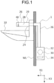
- FIG. 1 is a right side view of a hand dryer 1 according to a first embodiment.
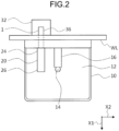
- FIG. 2 is a plan view of the hand dryer 1.
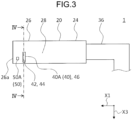
- FIG. 3 is a right side view of a housing 20 of the hand dryer 1.
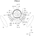
- FIG. 4 is a cross-section along line IV-IV of FIG. 3 .
- FIG. 5 is a cross-section along line V-V of FIG. 4 .
- FIGS. 1 and 2 illustrate the hand dryer 1 installed on a washstand 10.
- the washstand 10 includes a washbowl 12.
- the washstand 10 is installed on a wall WL.
- the washbowl 12 is formed in the shape of a bowl to receive and store water.
- the washbowl 12 has a drainage outlet 14 in a bottom.
- the drainage outlet 14 is connected to a drain pipe (not illustrated) underneath.
- the washstand 10 also includes a water discharger 16.
- the water discharger 16 is disposed to discharge water toward an inner side of the washbowl 12.
- the provided water discharger 16 extends in a back-to-front direction X1.
- the back-to-front direction X1 is a direction toward a side where a user who uses the washstand 10 is.
- the water discharger 16 is, for example, a faucet connected to a water pipe.
- the water discharger 16 is passed through the washstand 10 and is connected to a water supply that supplies the water to be discharged.
- the water discharger 16 includes a conventional sensor, a control circuit, and a solenoid valve that are not illustrated. As the sensor detects hands of the user, the solenoid valve opens automatically, and the water is discharged from the water discharger 16.
- the hand dryer 1 includes the housing 20 and a nozzle 40.
- the housing 20 extends in the shape of a tube and internally includes a draft passage 22 connected to a high pressure air source.
- the housing 20 extends above the washbowl 12 from an outer side of the washbowl 12.
- the housing 20 according to the present embodiment is cylindrically formed and extends above the washbowl 12 in the back-to-front direction X1 from an upper part of the washstand 10.
- a portion of the housing 20 that projects from the upper part of the washstand 10 is disposed near and in parallel with the water discharger 16.
- the housing 20 has a projecting length set to range from about 100 mm to 300 mm.
- the housing 20 is made of, for example, metal.
- a blower 30 is provided as a high pressure air source.
- the blower 30 is housed in a power unit case 32 provided adjacently to the wall WL.
- the blower 30 includes: a motor; and a turbofan that is rotated by the motor.
- the blower 30 is configured to draw in air from a suction opening not illustrated and produce high pressure air.
- the suction opening is provided with a detachable air filter (not illustrated) that collects dust, dirt, and others in the air.
- the air filter may be, for example, a resin mesh, a metal mesh, another mesh, or a high-efficiency particulate air (HEPA) filter capable of collecting finer dust particles.
- the power unit case 32 also houses a control circuit 34 that performs operation control on the blower 30.
- the control circuit 34 is connected to the blower 30 by, for example, a signal line.
- a discharge side of the blower 30 is connected to one end of an air duct 36. Another end of the air duct 36 is connected to a base end 24 of the housing 20.
- the air duct 36 is a tubular member having an interior that allows the air to pass through. In the present embodiment, the air duct 36 is passed through the wall WL and the upper part of the washstand 10 to be connected to the base end 24 of the housing 20.
- the high pressure air produced by the blower 30 is supplied from the air duct 36 to a leading end 26 of the housing 20 through the internal draft passage 22 of the housing 20.
- the air duct 36 is molded from, for example, a flexible resin.
- the nozzle 40 is provided at sides 28 of the housing 20 and ejects the air flowing through the draft passage 22 in fan shapes.
- the sides 28 refer to the sides 28 on a right and a left side of the back-to-front direction X1.
- the nozzle 40 is disposed at the leading end 26 of the housing 20 above the washbowl 12. In other words, the nozzle 40 is disposed where the back-to-front direction X1 points, forwardly of a middle position of the housing 20 along the back-to-front direction X1, and near a front edge 26a of the leading end 26.
- the nozzle 40 includes a right-hand nozzle 40A that blows air against the user's right hand and a left-hand nozzle 40B that blows air against the user's left hand.
- the right-hand nozzle 40A and the left-hand nozzle 40B are arranged in a left-to-right direction X2 symmetrically with respect to a middle part of the leading end 26 of the housing 20 along the left-to-right direction X2.
- the left-to-right direction X2 is orthogonal to the back-to-front direction X1 here.
- the nozzle 40 includes air outlets 42 for ejecting the high pressure air supplied through the draft passage 22.
- Each of the air outlets 42 is an opening providing communication between the draft passage 22 and an exterior of the housing 20.
- each air outlet 42 is an elongate slit formed in the housing 20. Therefore, each air outlet 42 has an outer opening edge 44 that is flush with an external surface of the housing 20.
- Each air outlet 42 has a slit length running in a circumferential direction of the housing 20 that has a circular cross-section.
- Each air outlet 42 formed in the housing 20 has one lengthwise slit edge at an upper position and another lengthwise slit edge at a lower position.
- Each air outlet 42 has a uniform slit width (transverse slit dimension) set to, for example, less than or equal to 2 mm.
- the nozzle 40 is disposed slenderly like lines on a side surface of the housing 20, and the back-to-front direction X1 in which the housing 20 extends intersects the slit length, which indicates a longitudinal direction of the nozzle 40.
- the back-to-front direction X1 is orthogonal to a longitudinal direction of the slit.
- Each of heads 46 of the nozzle 40 defines the outer opening edge 44 of the air outlet 42 and has a shape that bulges in an outward direction from an inner side of the housing 20.
- each formed head 46 when viewed from a direction parallel to the back-to-front direction X1, each formed head 46 has the shape of an arc, bulging in the outward direction from the inner side of the housing 20.
- the head 46 of this shape causes the high pressure air to be ejected from the air outlet 42 in the fan shape, spreading out like an open fan.
- Ejection directions A1 of the air ejected in the fan shape from the nozzle 40 are within a range downward from a horizontal direction.
- a specific description is provided with reference to FIG. 4 . Since the right-hand nozzle 40A and the left-hand nozzle 40B are symmetrical in the left-to-right direction X2, the right-hand nozzle 40A is described below, and a description of the left-hand nozzle 40B is omitted.
- the left-to-right direction X2 is one horizontal direction
- a top-to-bottom direction X3 corresponds to a vertical direction.
- the top-to-bottom direction X3 is orthogonal to the back-to-front direction X1 and to the left-to-right direction X2. As illustrated in FIG.
- the ejection directions A1 of the air from the right-hand nozzle 40A are within the downward range from the left-to-right direction X2 to the top-to-bottom direction X3. Assuming an angle is 0° in the left-to-right direction X2 and increases downward from the left-to-right direction X2 in the example of FIG. 4 , the ejection directions A1 of the air are within the range between 0° and 60°. Moreover, the ejection directions A1 of the air are orthogonal to the back-to-front direction X1.
- an upper end 42a of the air outlet 42 includes a plane parallel to the left-to-right direction X2, so the air is ejected in the left-to-right direction X2 near the upper end 42a.
- a lower end 42b of the air outlet 42 includes a plane parallel to a direction inclined downward at 60° to the left-to-right direction X2, so the air is ejected in the direction that is inclined downward at 60° to the left-to-right direction X2 near the lower end 42b.
- a length from the upper end 42a to the lower end 42b of the air outlet 42 is set smaller than a width of the user's hand TE here.
- the ejection directions A1 of the air from the right-hand nozzle 40A may be within a range between, for example, 0° and 30°.
- the nozzle 40 includes angle determiners that each determines an angle over which the ejected air spreads.
- the angle determiner determines edges of a fan-shaped expanse of air.
- the upper end 42a and the lower end 42b of each air outlet 42 function as the angle determiner.
- the plane of the upper end 42a continuous with the outer opening edge 44 of the air outlet 42 is near the outer opening edge 44 and is parallel to the left-to-right direction X2, and the most upward ejection direction A1 of the ejected air is along this plane of the upper end 42a. With its plane, the upper end 42a thus determines an upper limit for the fan-shaped expanse of air.
- the plane of the lower end 42b continuous with the outer opening edge 44 of the air outlet 42 is near the outer opening edge 44 and is parallel to the direction that is inclined downward at 60° to the left-to-right direction X2, and the most downward ejection direction A1 of the ejected air is along this plane of the lower end 42b. With its plane, the lower end 42b thus determines a lower limit for the fan-shaped expanse of air.
- the angle over which the air ejected from the nozzle 40 spreads is determined by an angle formed by the plane of the upper end 42a and the plane of the lower end 42b.
- the plane of the upper end 42a and the plane of the lower end 42b have such a positional relation that these planes come closer to each other in a direction away from the outer opening edge 44, that is to say, in the direction closer to the inner side of the housing 20.
- the angle that is formed by the plane of the upper end 42a and the plane of the lower end 42b is 60°. Therefore, although there is some diffusion, the air ejected from the nozzle 40 spreads in the fan shape over an angle of about 60°.
- the housing 20 also includes, between the right-hand nozzle 40A and the left-hand nozzle 40B, a brace 48 that does not allow the air to be ejected.
- the brace 48 is provided in a vertically lower part of the housing 20 between the right-hand nozzle 40A and the left-hand nozzle 40B.
- the hand dryer 1 further includes a hand detector 50 that detects whether or not the hands of the user who uses the hand dryer 1 are present.
- the hand detector 50 is provided forwardly of the nozzle 40 at the housing 20. In other words, the hand detector 50 is disposed closer to the user than the nozzle 40 is.
- the hand detector 50 is housed in a sensor housing 52 provided at the leading end 26 of the housing 20 and is attached to the sensor housing 52 in the present embodiment.
- the hand detector 50 has a detection range that is set to enable the detection of the hand extended to the leading end 26 of the housing 20 from in front of the leading end 26.
- the hand detector 50 includes a hand detector 50A for the right hand and a hand detector 50B for the left hand.
- the hand detector 50A for the right hand is disposed forwardly of and near the right-hand nozzle 40A.
- the hand detector 50B for the left hand is disposed forwardly of and near the left-hand nozzle 40B.
- the hand detector 50 is composed of, for example, a photoelectric sensor and thus can be miniaturized.
- the hand detector 50 is connected to the control circuit 34 by a cable 54.
- the cable 54 transmits a signal from the hand detector 50 to the control circuit 34.
- the sensor housing 52 housing the hand detector 50 is disconnected from the draft passage 22 of the housing 20.
- the cable 54 extends from the sensor housing 52 to the control circuit 34, running through a wall between the sensor housing 52 and the draft passage 22, the draft passage 22, and the air duct 36.
- a part where the cable 54 is passed from the sensor housing 52 into the draft passage 22 is sealed with a component that, made of rubber, silicone, or another material, prevents coming and going of the air between the sensor housing 52 and the draft passage 22.
- FIG. 6 is a control block diagram for the hand dryer 1.
- the hand detector 50 Upon detecting the user's hand, the hand detector 50 outputs the signal to the control circuit 34.
- the control circuit 34 Upon receiving from the hand detector 50 the signal that indicates that the hand has been detected, the control circuit 34 outputs to the blower 30 a signal that operates the blower 30.
- the blower 30 operates in accordance with the signal output from the control circuit 34 and produces high pressure air.
- the high pressure air produced by the blower 30 is supplied from the air duct 36 to the nozzle 40 through the draft passage 22 and is ejected from the air outlets 42.
- Output of the blower 30 is set to cause, for example, the air to be ejected from the air outlets 42 at a speed of 80 m/s or higher.
- the two hand detectors 50A and 50B are provided for the right and left hands as the hand detector 50, and in the setting, the blower 30 operates when either of the hand detector 50 has detected the user's hand.
- the hand dryer 1 includes the housing 20 that internally includes the draft passage 22 connected to the high pressure air source and the nozzle 40 that is provided at the sides 28 of the housing 20 and ejects the air flowing through the draft passage 22 in the fan shapes.
- Providing the nozzle 40 at the sides 28 of the housing 20 as described above prevents a situation where the user has difficulty seeing the user's hands that are, for example, under the housing 20, overlapping the housing 20 when drying the hands. Since the nozzle 40 ejects the air in the fan shape, the ejected air flows with increasing width in a direction away from the nozzle 40. Therefore, with the airflow being wider at a position away from the nozzle 40 than the user's hand TE, as illustrated in FIG. 4 , the hand is enabled to be dried well even at the position away from the nozzle 40. Since the hand is thus enabled to be dried at the position away from the nozzle 40 without overlapping the housing 20, an easy check can be made on how well the hand is dried while the hands are dried, enabling better user-friendliness.
- the nozzle 40 includes the air outlets 42, each of which is the opening providing the communication between the draft passage 22 and the exterior of the housing 20, and each head 46 of the nozzle 40 defines the outer opening edge 44 of the air outlet 42 and has the shape that bulges in the outward direction from the inner side of the housing 20. This configuration enables the air to be ejected in the fan shapes from the nozzle 40.
- the length from the upper end 42a, the uppermost end, to the lower end 42b, the lowermost end, of the air outlet 42 is shorter than the width of the user's hand TE. Since the air is ejected in the fan shape from the nozzle 40 in the present embodiment, the ejected air is enabled to flow with increasing width in the direction away from the nozzle 40. Therefore, making the length from the uppermost end to the lowermost end of the air outlet 42 shorter than the width of the user's hand TE enables the nozzle 40 and the housing 20 to be smaller in size and then the generation of the airflow wider than the user's hand TE. With the housing 20 thus being smaller in size, the range over which the user moves the hand when drying the hands can be kept wider, further improving the user-friendliness.
- the outer opening edge 44 of the air outlet 42 is flush with the external surface of the housing 20.
- This configuration has the nozzle 40 housed within external dimensions of the housing 20 without, for example, having the nozzle 40 protrude from the external surface of the housing 20, thus enabling the hand dryer 1 to be smaller in size.
- the nozzle 40 is provided at the leading end 26 of the housing 20. This configuration has the nozzle 40 closer to the user, thus making the hand dryer 1 user-friendlier.
- the ejection directions A1 of the air from the nozzle 40 are within the range downward from the left-to-right direction X2, which is the one horizontal direction. Since the air is not ejected upward from the nozzle 40, this configuration can prevent the ejected air from the nozzle 40 from directly blowing against a face or another part of the user or blowing water droplets off the user's hands upward.
- the ejection directions A1 are within the range between 0° and 60°. Since the nozzle 40 ejects the air in the fan shape within the range between 0° and 60°, the user is enabled to dry the hand, having the hand angled to easily see how well the hand is dried. Thus the hand dryer 1 is made user-friendlier.
- the nozzle 40 includes the right-hand nozzle 40A and the left-hand nozzle 40B, and the housing 20 includes, between the right-hand nozzle 40A and the left-hand nozzle 40B, the brace 48 that does not allow the air to be ejected.
- the brace 48 that does not allow the air to be ejected.
- Providing the right-hand nozzle 40A that ejects the air for drying the user's right hand and the left-hand nozzle 40B that ejects the air for drying the user's left hand in this way improves the user-friendliness.
- Providing the brace 48 between the right-hand nozzle 40A and the left-hand nozzle 40B creates an ejected air-free space between the airflow from the right-hand nozzle 40A and the airflow from the left-hand nozzle 40B. This enables the user to sense and learn that the right-hand nozzle 40A and the left-hand nozzle 40B are provided separately.
- the brace 48 is provided in the vertically lower part of the housing 20 between the right-hand nozzle 40A and the left-hand nozzle 40B.
- a receiving member such as the washbowl 12
- Providing the brace 48 in the vertically lower part of the housing 20 between the right-hand nozzle 40A and the left-hand nozzle 40B as in the present embodiment prevents a situation where the air is downwardly ejected directly from the vertically lower part of the housing 20, strikes against the receiving member, and blows the water droplets that in turn wet surroundings and the user.
- the hand dryer 1 further includes, forwardly of the nozzle 40 at the housing 20, the hand detector 50 that detect whether or not the hands are present. Because of being disposed forwardly of the nozzle 40 as described above, the hand detector 50 is enabled to detect the user's hands ahead of the nozzle 40 when the user extends the hands to the nozzle 40 and cause the hand dryer 1 to operate. This results in no waiting time before the air is ejected from the nozzle 40 when the user has extended the hands to the nozzle 40, improving the user-friendliness.
- the hand dryer 1 further includes the washstand 10 that includes the washbowl 12.
- the housing 20 extends above the washbowl 12 from the outer side of the washbowl 12, and the nozzle 40 is disposed above the washbowl 12.
- a space between the washbowl 12 and the housing 20 above the washbowl 12 is where the user places and dries the hands, and the air ejected from the nozzle 40 is blown against the user's hands placed in this drying space to dry the hands.
- the hands are enabled to be dried at positions away from the nozzle 40 without overlapping the housing 20 in the present embodiment, the user is enabled to be free to place the hands from any directions the user likes without interfering with the housing 20.
- the user since there is no concern about contact between the hands placed in the drying space and the housing 20, the user is also enabled to freely move the hands during drying and dry the hands in a posture the user prefers. In this way, the user-friendliness is enabled to improve.
- the housing 20 extends in the shape of the tube, and the air is ejected from the nozzle 40 in the fan shapes when viewed from the extending direction of the housing 20, that is to say, from the back-to-front direction X1 in the present embodiment.
- the housing 20 often extends toward the user, and in that case, the air is ejected in the fan shapes from the nozzle 40 when viewed from the user. This facilitates the user's insertion of the hand into the fan-shaped airflow ejected from the nozzle 40, improving the user-friendliness.
- the nozzle 40 is disposed slenderly like lines on the side surface of the housing 20, and the back-to-front direction X1 in which the housing 20 extends intersects the longitudinal direction of the nozzle 40.
- the nozzle 40 Since the longitudinal direction of the nozzle 40 is thus at the predetermined angle to the back-to-front direction X1 in which the housing 20 extends, the nozzle 40 is enabled to eject the air in a plane that intersects the back-to-front direction X1 at the predetermined angle.
- the right-hand nozzle 40A and the left-hand nozzle 40B are arranged in the left-to-right direction X2 symmetrically with respect to the middle part of the leading end 26 of the housing 20 along the left-to-right direction X2, but are not limited to this symmetrical arrangement in the left-to-right direction X2.
- the sensor housing 52 may be detachable from the leading end 26 of the housing 20. This facilitates assembly of the hand detector 50 and the sensor housing 52 and enables improved maintainability.
- the two hand detectors 50A and 50B are provided for the right and left hands as the hand detector 50, this is not limiting.
- only one of the hand detector 50 either the hand detector 50A for the right hand or the hand detector 50B for the left hand, may be provided.
- the single hand detector 50 may be provided at the middle part of the leading end 26 of the housing 20 along the left-to-right direction X2.
- FIG. 7 is a right side view of a housing 120 of a hand dryer 101 according to the present embodiment.
- descriptions of parts similar to those in the first embodiment are omitted.
- a nozzle 140 provided at the housing 120 according to the present embodiment includes an air outlet 142 that is different in shape than the air outlet 42 of the nozzle 40 according to the first embodiment.
- the air outlet 142 has a greater opening width at an upper part than an opening width at a lower part.
- the air outlet 142 is formed in the shape of a slit, so the opening width is a slit width. The slit width is greatest at an upper end 142a of the air outlet 142, decreases in a direction toward a lower end 142b of the air outlet 142, and is smallest at the lower end 142b.
- a user extends a hand with a thumb at an upper position when drying the hand with the hand dryer 101.
- Causing the air outlet 142 to have the greater opening width at the upper part than the opening width at the lower part as described above enables the air outlet 142 to eject an increased air quantity from the upper part. Therefore, a part that is difficult to dry, such as the thumb, is enabled to be exposed to the increased air quantity, so effective hand drying is possible.
- ejection of a decreased air quantity from the lower part of the air outlet 142 is enabled, a decreased quantity of air can be directed toward the washbowl 12 disposed beneath, resulting in a weakened collision with the washbowl 12.
- FIG. 8 is a right side view of a housing 220 of a hand dryer 201 according to the present embodiment.
- descriptions of parts similar to those in the first embodiment are omitted.
- a nozzle 240 provided at the housing 220 according to the present embodiment includes an air outlet 242 disposed differently from the air outlet 42 of the nozzle 40 according to the first embodiment. As illustrated in FIG. 8 , the disposed air outlet 242 comes to a front position as the air outlet 242 runs downward.
- the air outlet 242 is formed in the shape of a slit. When viewed from a direction parallel to the left-to-right direction X2, the air outlet 242 extends in a straight line, and a longitudinal direction in which the air outlet 242 extends is inclined at a certain angle to the top-to-bottom direction X3, which refers to the vertical direction.
- the angle B1 at which the longitudinal direction of the air outlet 242 is inclined to the top-to-bottom direction X3 is acute and is set to within a range that is greater than 0° and 45° or smaller.
- the water discharger 16 of the washstand 10 is at a height that is set to allow a user to be in an easy posture when inserting hands underneath the water discharger 16 and washing the hands with water that is discharged from the water discharger 16. Specifically, in a slightly stooping posture, the user inserts the hands underneath the water discharger 16 and washes the hands with the water discharged from the water discharger 16.
- the housing 220 of the hand dryer 201 is disposed on a nearby right side or a nearby left side of the water discharger 16 at a certain distance from the water discharger 16 and at generally the same height as the water discharger 16. Therefore, when using the hand dryer 201, the user also assumes the same slightly stooping posture as when using the water discharger 16.
- the hands are pointed diagonally downward toward the wall WL. Therefore, disposing the air outlet 242 so that, as described above, the air outlet 242 comes to the front position as the air outlet 242 runs downward enables ejected air from the air outlet 242 to blow at an angle close to a right angle to back-and-forth movement of the user's hand, thus more effectively blowing water droplets off the user's hand and enabling improved drying efficiency.
- the air outlet 242 extends in the straight line when viewed from the direction parallel to the left-to-right direction X2 in the present embodiment, this is not limiting.
- the air outlet 242 may extend in a curve when viewed from a direction parallel to the left-to-right direction X2, provided that the air outlet 242 is disposed to come to a front position as the air outlet 242 runs downward.
- the air outlet of the nozzle is the single slit in the above-described embodiments but is not limited to this.
- a plurality of air outlets 342 may be arranged side by side.
- FIG. 9 is a right side view of the housing 320.
- the nozzle 340 includes two slit-shaped air outlets 342 arranged side by side in the back-to-front direction X1.
- a nozzle 440 may include a plurality of air outlets 442 that are small holes arranged in a line.
- FIG. 10 is a right side view of the housing 420.
- the nozzle 440 includes the plurality of air outlets 442, which are the holes that are circular and arranged in the line.
- this configuration includes a connective part between the small holes as openings, enabling the nozzle 440 to have reinforced strength.
- the small holes are not limited to the circular shapes and may be rectangular.
- the nozzle 40 includes the right-hand and left-hand nozzles 40A and 40B that are provided separately, this is not limiting.
- a single nozzle 540 may be provided, having a right-hand nozzle and a left-hand nozzle continuous with each other.
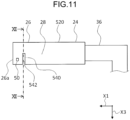
- FIG. 11 is a right side view of the housing 520.
- FIG. 12 is a cross-section along line XII-XII of FIG. 11 .
- the nozzle 540 includes an air outlet 542 that is a semicircular arc-shaped slit when viewed from a direction parallel to the back-to-front direction X1.
- This configuration allows ejection of air from the air outlet 542 to also take place right under the housing 520, providing a wider range of air ejection. Therefore, improved user-friendliness can be provided when a user dries not only hands but also arms and other parts.
- a housing 620 as a fourth modification may be provided with a substantially L-shaped leading end 626 that extends in the back-to-front direction X1 and bends in the top-to-bottom direction X3.
- FIG. 13 is a right side view of the housing 620.
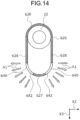
- FIG. 14 is a cross-section along line XIV-XIV of FIG. 13 .
- the leading end 626 of the housing 620 extends in the shape of a cylinder in the top-to-bottom direction X3 and has a leading edge part 627 that is formed in the shape of a hemisphere.
- a nozzle 640 is provided at sides 628 of the leading end 626 of the housing 620.
- the nozzle 640 includes air outlets 642 in the hemisphere-shaped part of the leading end 626, and air is ejected from the air outlets 642 in fan shapes.
- Each of the air outlets 642 is formed in the shape of an elongate slit and extends linearly along the top-to-bottom direction X3 when viewed from a direction parallel to the left-to-right direction X2.
- the housing 620 is provided with a hand detector 650 at a position that is closer to a front edge 626a of the leading end 626 than the nozzle 640 is and in front of the nozzle 640.
- a leading end 726 of a housing 720 as a fifth modification may be provided with a nozzle 740 that is formed separately from the housing 720 and projects from an external surface of the leading end 726 of the housing 720.
- FIG. 15 is a right side view of the housing 720.
- FIG. 16 is a cross-section along line XVI-XVI of FIG. 15 .
- the nozzle 740 is provided at sides 728 of the leading end 726 of the housing 720.
- the nozzle 740 includes air outlets 742 that are each formed in the shape of an elongate slit and extend linearly along the top-to-bottom direction X3 when viewed from a direction parallel to the left-to-right direction X2.
- the nozzle 740 includes head 746 that each define an outer opening edge 744 of the air outlet 742.
- Each head 746 is provided at an outwardly protrusive position compared with the external surface of the leading end 726 of the housing 720 and has a shape that bulges in an outward direction from an inner side of the housing 720.
- each formed head 746 when viewed from a direction parallel to the back-to-front direction X1, each formed head 746 includes an arc, bulging in the outward direction from the inner side of the housing 720.
- the head 746 of this shape causes high pressure air to be ejected from the air outlet 742 in a fan shape, spreading out like an open fan.
- the shape of the head 746 as viewed from the direction parallel to the back-to-front direction X1 is not limited the arc and may include a shape as a combination of plural curved lines, a shape as a combination of a straight line and a curved line, or another shape, provided that the shape bulges in the outward direction from the inner side of the housing 720.
- the nozzle 40 is enabled to secure a sufficient length from the draft passage 22 to the outer opening edge 744 of the air outlet 742. Since air passing through an interior of the nozzle 40 is rectified over a longer distance, the rectification of the air to be ejected in the fan shape from the air outlet 742 is enabled to be more reliable.
- the housing that extends in the back-to-front direction X1 has a circular cross-sectional outline orthogonal to the back-to-front direction X1 in the above-described embodiments, this is not limiting.
- the cross-sectional outline may be polygonal or elliptical, or of a shape that is a combination of plural curved lines, a shape that is a combination of a straight line and a curved line, or another shape.
- a housing 820 as a sixth modification may have an octagonal cross-sectional outline orthogonal to the back-to-front direction X1.
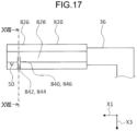
- FIG. 17 is a right side view of the housing 820.
- FIG. 18 is a cross-section along line XVIII-XVIII of FIG. 17 .
- a nozzle 840 is provided at sides 828 of a leading end 826 of the housing 820.
- the nozzle 840 includes air outlets 842 that are each formed in the shape of an elongate slit and extend linearly along the top-to-bottom direction X3 when viewed from a direction parallel to the left-to-right direction X2.
- Each of heads 846 of the nozzle 840 defines an outer opening edge 844 of the air outlet 842 and has a shape that bulges in an outward direction from an inner side of the housing 820.
- each formed head 846 when viewed from a direction parallel to the back-to-front direction X1, each formed head 846 is substantially V-shaped, bulging in the outward direction from the inner side of the housing 820.
- the head 846 of this shape causes high pressure air to be ejected from the air outlet 842 in a fan shape.
- the hand dryer provided according to the present disclosure enables an easy check on how well hands are dried while the hands are being dried.
Landscapes
- Health & Medical Sciences (AREA)
- Public Health (AREA)
- Domestic Plumbing Installations (AREA)
Abstract
Description
- The present disclosure relates to a hand dryer.
- A hand dryer that dries wet hands after washing has been widely used. For example, a hand dryer described in
Patent Literature 1 extends over a sink and uses an air-knife to mechanically wipe water from a user's hands. This hand dryer includes two elongate air-knife discharge outlets. Each of the discharge outlets is connected to an air supply and discharges the air-knife down onto the hand of the user. The air-knife discharge outlets are arranged side by side over a basin of the sink. Each air-knife discharge outlet extends along a part of the hand dryer that is arranged at a dihedral angle such that an inboard end of the air-knife discharge outlet is below an outboard end of the air-knife discharge outlet. - Patent Literature 1:
Japanese Translation of PCT International Application Laid-open No. 2015-523127 FIGS. 3 to 6 ) - The user of the hand dryer described in
Patent Literature 1 inserts the hands between the parts of the hand dryer that are provided with the air-knife discharge outlets and the basin of the sink and dries the hands under the parts of the hand dryer. In this case, there is a problem that the parts of the hand dryer are obstructive, making it difficult for the user to see how well his or her hands are dried and degrading user-friendliness. - The present disclosure has been made to solve the above-mentioned problems and to provide a user-friendlier hand dryer that enables an easy check on how well hands are dried.
- A hand dryer according to the present disclosure includes: a housing internally including a draft passage connected to a high pressure air source; and a nozzle adapted to eject air flowing through the draft passage in a fan shape, the nozzle being provided at a side of the housing.
- While hands are being dried with the hand dryer according to the present disclosure, an easy check can be made on how well the hands are dried, enabling better user-friendliness.
-
-
FIG. 1 is a right side view of a hand dryer according to a first embodiment. -
FIG. 2 is a plan view of the hand dryer according to the first embodiment. -
FIG. 3 is a right side view of a housing of the hand dryer according to the first embodiment. -
FIG. 4 is a cross-section along line IV-IV ofFIG. 3 . -
FIG. 5 is a cross-section along line V-V ofFIG. 4 . -
FIG. 6 is a control block diagram for the hand dryer according to the first embodiment. -
FIG. 7 is a right side view of a housing of a hand dryer according to a second embodiment. -
FIG. 8 is a right side view of a housing of a hand dryer according to a third embodiment. -
FIG. 9 is a right side view of a housing as a first modification. -
FIG. 10 is a right side view of a housing as a second modification. -
FIG. 11 is a right side view of a housing as a third modification. -
FIG. 12 is a cross-section along line XII-XII ofFIG. 11 . -
FIG. 13 is a right side view of a housing as a fourth modification. -
FIG. 14 is a cross-section along line XIV-XIV ofFIG. 13 . -
FIG. 15 is a right side view of a housing as a fifth modification. -
FIG. 16 is a cross-section along line XVI-XVI ofFIG. 15 . -
FIG. 17 is a right side view of a housing as a sixth modification. -
FIG. 18 is a cross-section along line XVIII-XVIII ofFIG. 17 . - With reference to the accompanying drawings, a description is hereinafter provided of embodiments. In the drawings, identical or corresponding parts have the same reference characters.
-
FIG. 1 is a right side view of ahand dryer 1 according to a first embodiment.FIG. 2 is a plan view of thehand dryer 1.FIG. 3 is a right side view of ahousing 20 of thehand dryer 1.FIG. 4 is a cross-section along line IV-IV ofFIG. 3 .FIG. 5 is a cross-section along line V-V ofFIG. 4 .FIGS. 1 and2 illustrate thehand dryer 1 installed on awashstand 10. - The
washstand 10 includes awashbowl 12. In the present embodiment, thewashstand 10 is installed on a wall WL. Thewashbowl 12 is formed in the shape of a bowl to receive and store water. Thewashbowl 12 has adrainage outlet 14 in a bottom. Thedrainage outlet 14 is connected to a drain pipe (not illustrated) underneath. - The
washstand 10 also includes awater discharger 16. Thewater discharger 16 is disposed to discharge water toward an inner side of thewashbowl 12. In the present embodiment, the providedwater discharger 16 extends in a back-to-front direction X1. The back-to-front direction X1 is a direction toward a side where a user who uses thewashstand 10 is. Thewater discharger 16 is, for example, a faucet connected to a water pipe. Thewater discharger 16 is passed through thewashstand 10 and is connected to a water supply that supplies the water to be discharged. Thewater discharger 16 includes a conventional sensor, a control circuit, and a solenoid valve that are not illustrated. As the sensor detects hands of the user, the solenoid valve opens automatically, and the water is discharged from thewater discharger 16. - The
hand dryer 1 includes thehousing 20 and anozzle 40. Thehousing 20 extends in the shape of a tube and internally includes adraft passage 22 connected to a high pressure air source. Thehousing 20 extends above thewashbowl 12 from an outer side of thewashbowl 12. Thehousing 20 according to the present embodiment is cylindrically formed and extends above thewashbowl 12 in the back-to-front direction X1 from an upper part of thewashstand 10. A portion of thehousing 20 that projects from the upper part of thewashstand 10 is disposed near and in parallel with thewater discharger 16. In consideration of the user-friendliness, thehousing 20 has a projecting length set to range from about 100 mm to 300 mm. Thehousing 20 is made of, for example, metal. - In the present embodiment, a
blower 30 is provided as a high pressure air source. Theblower 30 is housed in apower unit case 32 provided adjacently to the wall WL. Theblower 30 includes: a motor; and a turbofan that is rotated by the motor. Theblower 30 is configured to draw in air from a suction opening not illustrated and produce high pressure air. The suction opening is provided with a detachable air filter (not illustrated) that collects dust, dirt, and others in the air. The air filter may be, for example, a resin mesh, a metal mesh, another mesh, or a high-efficiency particulate air (HEPA) filter capable of collecting finer dust particles. Thepower unit case 32 also houses acontrol circuit 34 that performs operation control on theblower 30. Thecontrol circuit 34 is connected to theblower 30 by, for example, a signal line. - A discharge side of the
blower 30 is connected to one end of anair duct 36. Another end of theair duct 36 is connected to abase end 24 of thehousing 20. Theair duct 36 is a tubular member having an interior that allows the air to pass through. In the present embodiment, theair duct 36 is passed through the wall WL and the upper part of thewashstand 10 to be connected to thebase end 24 of thehousing 20. The high pressure air produced by theblower 30 is supplied from theair duct 36 to aleading end 26 of thehousing 20 through theinternal draft passage 22 of thehousing 20. Theair duct 36 is molded from, for example, a flexible resin. - The
nozzle 40 is provided atsides 28 of thehousing 20 and ejects the air flowing through thedraft passage 22 in fan shapes. In the present exemplary embodiment, thesides 28 refer to thesides 28 on a right and a left side of the back-to-front direction X1. Thenozzle 40 is disposed at theleading end 26 of thehousing 20 above thewashbowl 12. In other words, thenozzle 40 is disposed where the back-to-front direction X1 points, forwardly of a middle position of thehousing 20 along the back-to-front direction X1, and near afront edge 26a of theleading end 26. Thenozzle 40 includes a right-hand nozzle 40A that blows air against the user's right hand and a left-hand nozzle 40B that blows air against the user's left hand. In the present embodiment, the right-hand nozzle 40A and the left-hand nozzle 40B are arranged in a left-to-right direction X2 symmetrically with respect to a middle part of theleading end 26 of thehousing 20 along the left-to-right direction X2. The left-to-right direction X2 is orthogonal to the back-to-front direction X1 here. - The
nozzle 40 includesair outlets 42 for ejecting the high pressure air supplied through thedraft passage 22. Each of theair outlets 42 is an opening providing communication between thedraft passage 22 and an exterior of thehousing 20. In the present embodiment, eachair outlet 42 is an elongate slit formed in thehousing 20. Therefore, eachair outlet 42 has an outer opening edge 44 that is flush with an external surface of thehousing 20. Eachair outlet 42 has a slit length running in a circumferential direction of thehousing 20 that has a circular cross-section. Eachair outlet 42 formed in thehousing 20 has one lengthwise slit edge at an upper position and another lengthwise slit edge at a lower position. Eachair outlet 42 has a uniform slit width (transverse slit dimension) set to, for example, less than or equal to 2 mm. With this configuration, thenozzle 40 is disposed slenderly like lines on a side surface of thehousing 20, and the back-to-front direction X1 in which thehousing 20 extends intersects the slit length, which indicates a longitudinal direction of thenozzle 40. In the present embodiment in particular, the back-to-front direction X1 is orthogonal to a longitudinal direction of the slit. Each ofheads 46 of thenozzle 40 defines the outer opening edge 44 of theair outlet 42 and has a shape that bulges in an outward direction from an inner side of thehousing 20. Specifically, when viewed from a direction parallel to the back-to-front direction X1, each formedhead 46 has the shape of an arc, bulging in the outward direction from the inner side of thehousing 20. Thehead 46 of this shape causes the high pressure air to be ejected from theair outlet 42 in the fan shape, spreading out like an open fan. - Ejection directions A1 of the air ejected in the fan shape from the
nozzle 40 are within a range downward from a horizontal direction. A specific description is provided with reference toFIG. 4 . Since the right-hand nozzle 40A and the left-hand nozzle 40B are symmetrical in the left-to-right direction X2, the right-hand nozzle 40A is described below, and a description of the left-hand nozzle 40B is omitted. InFIG. 4 , the left-to-right direction X2 is one horizontal direction, and a top-to-bottom direction X3 corresponds to a vertical direction. The top-to-bottom direction X3 is orthogonal to the back-to-front direction X1 and to the left-to-right direction X2. As illustrated inFIG. 4 , the ejection directions A1 of the air from the right-hand nozzle 40A are within the downward range from the left-to-right direction X2 to the top-to-bottom direction X3. Assuming an angle is 0° in the left-to-right direction X2 and increases downward from the left-to-right direction X2 in the example ofFIG. 4 , the ejection directions A1 of the air are within the range between 0° and 60°. Moreover, the ejection directions A1 of the air are orthogonal to the back-to-front direction X1. In this case, anupper end 42a of theair outlet 42 includes a plane parallel to the left-to-right direction X2, so the air is ejected in the left-to-right direction X2 near theupper end 42a. Alower end 42b of theair outlet 42 includes a plane parallel to a direction inclined downward at 60° to the left-to-right direction X2, so the air is ejected in the direction that is inclined downward at 60° to the left-to-right direction X2 near thelower end 42b. A length from theupper end 42a to thelower end 42b of theair outlet 42 is set smaller than a width of the user's hand TE here. The ejection directions A1 of the air from the right-hand nozzle 40A may be within a range between, for example, 0° and 30°. - In order to eject the air in the fan shapes, the
nozzle 40 includes angle determiners that each determines an angle over which the ejected air spreads. The angle determiner determines edges of a fan-shaped expanse of air. In the present embodiment, theupper end 42a and thelower end 42b of eachair outlet 42 function as the angle determiner. Specifically, the plane of theupper end 42a continuous with the outer opening edge 44 of theair outlet 42 is near the outer opening edge 44 and is parallel to the left-to-right direction X2, and the most upward ejection direction A1 of the ejected air is along this plane of theupper end 42a. With its plane, theupper end 42a thus determines an upper limit for the fan-shaped expanse of air. The plane of thelower end 42b continuous with the outer opening edge 44 of theair outlet 42 is near the outer opening edge 44 and is parallel to the direction that is inclined downward at 60° to the left-to-right direction X2, and the most downward ejection direction A1 of the ejected air is along this plane of thelower end 42b. With its plane, thelower end 42b thus determines a lower limit for the fan-shaped expanse of air. The angle over which the air ejected from thenozzle 40 spreads is determined by an angle formed by the plane of theupper end 42a and the plane of thelower end 42b. The plane of theupper end 42a and the plane of thelower end 42b have such a positional relation that these planes come closer to each other in a direction away from the outer opening edge 44, that is to say, in the direction closer to the inner side of thehousing 20. The angle that is formed by the plane of theupper end 42a and the plane of thelower end 42b is 60°. Therefore, although there is some diffusion, the air ejected from thenozzle 40 spreads in the fan shape over an angle of about 60°. - The
housing 20 also includes, between the right-hand nozzle 40A and the left-hand nozzle 40B, abrace 48 that does not allow the air to be ejected. Thebrace 48 is provided in a vertically lower part of thehousing 20 between the right-hand nozzle 40A and the left-hand nozzle 40B. - The
hand dryer 1 further includes ahand detector 50 that detects whether or not the hands of the user who uses thehand dryer 1 are present. Thehand detector 50 is provided forwardly of thenozzle 40 at thehousing 20. In other words, thehand detector 50 is disposed closer to the user than thenozzle 40 is. As illustrated inFIG. 5 , thehand detector 50 is housed in asensor housing 52 provided at theleading end 26 of thehousing 20 and is attached to thesensor housing 52 in the present embodiment. Thehand detector 50 has a detection range that is set to enable the detection of the hand extended to theleading end 26 of thehousing 20 from in front of theleading end 26. Thehand detector 50 includes ahand detector 50A for the right hand and ahand detector 50B for the left hand. Thehand detector 50A for the right hand is disposed forwardly of and near the right-hand nozzle 40A. Thehand detector 50B for the left hand is disposed forwardly of and near the left-hand nozzle 40B. - The
hand detector 50 is composed of, for example, a photoelectric sensor and thus can be miniaturized. Thehand detector 50 is connected to thecontrol circuit 34 by acable 54. Thecable 54 transmits a signal from thehand detector 50 to thecontrol circuit 34. Thesensor housing 52 housing thehand detector 50 is disconnected from thedraft passage 22 of thehousing 20. As illustrated inFIG. 5 , thecable 54 extends from thesensor housing 52 to thecontrol circuit 34, running through a wall between thesensor housing 52 and thedraft passage 22, thedraft passage 22, and theair duct 36. A part where thecable 54 is passed from thesensor housing 52 into thedraft passage 22 is sealed with a component that, made of rubber, silicone, or another material, prevents coming and going of the air between thesensor housing 52 and thedraft passage 22. -
FIG. 6 is a control block diagram for thehand dryer 1. Upon detecting the user's hand, thehand detector 50 outputs the signal to thecontrol circuit 34. Upon receiving from thehand detector 50 the signal that indicates that the hand has been detected, thecontrol circuit 34 outputs to the blower 30 a signal that operates theblower 30. Theblower 30 operates in accordance with the signal output from thecontrol circuit 34 and produces high pressure air. The high pressure air produced by theblower 30 is supplied from theair duct 36 to thenozzle 40 through thedraft passage 22 and is ejected from theair outlets 42. Output of theblower 30 is set to cause, for example, the air to be ejected from theair outlets 42 at a speed of 80 m/s or higher. In the present embodiment, the twohand detectors hand detector 50, and in the setting, theblower 30 operates when either of thehand detector 50 has detected the user's hand. - As described above, the
hand dryer 1 according to the present embodiment includes thehousing 20 that internally includes thedraft passage 22 connected to the high pressure air source and thenozzle 40 that is provided at thesides 28 of thehousing 20 and ejects the air flowing through thedraft passage 22 in the fan shapes. - Providing the
nozzle 40 at thesides 28 of thehousing 20 as described above prevents a situation where the user has difficulty seeing the user's hands that are, for example, under thehousing 20, overlapping thehousing 20 when drying the hands. Since thenozzle 40 ejects the air in the fan shape, the ejected air flows with increasing width in a direction away from thenozzle 40. Therefore, with the airflow being wider at a position away from thenozzle 40 than the user's hand TE, as illustrated inFIG. 4 , the hand is enabled to be dried well even at the position away from thenozzle 40. Since the hand is thus enabled to be dried at the position away from thenozzle 40 without overlapping thehousing 20, an easy check can be made on how well the hand is dried while the hands are dried, enabling better user-friendliness. - The
nozzle 40 includes theair outlets 42, each of which is the opening providing the communication between thedraft passage 22 and the exterior of thehousing 20, and eachhead 46 of thenozzle 40 defines the outer opening edge 44 of theair outlet 42 and has the shape that bulges in the outward direction from the inner side of thehousing 20. This configuration enables the air to be ejected in the fan shapes from thenozzle 40. - The length from the
upper end 42a, the uppermost end, to thelower end 42b, the lowermost end, of theair outlet 42 is shorter than the width of the user's hand TE. Since the air is ejected in the fan shape from thenozzle 40 in the present embodiment, the ejected air is enabled to flow with increasing width in the direction away from thenozzle 40. Therefore, making the length from the uppermost end to the lowermost end of theair outlet 42 shorter than the width of the user's hand TE enables thenozzle 40 and thehousing 20 to be smaller in size and then the generation of the airflow wider than the user's hand TE. With thehousing 20 thus being smaller in size, the range over which the user moves the hand when drying the hands can be kept wider, further improving the user-friendliness. - The outer opening edge 44 of the
air outlet 42 is flush with the external surface of thehousing 20. This configuration has thenozzle 40 housed within external dimensions of thehousing 20 without, for example, having thenozzle 40 protrude from the external surface of thehousing 20, thus enabling thehand dryer 1 to be smaller in size. - The
nozzle 40 is provided at theleading end 26 of thehousing 20. This configuration has thenozzle 40 closer to the user, thus making thehand dryer 1 user-friendlier. - The ejection directions A1 of the air from the
nozzle 40 are within the range downward from the left-to-right direction X2, which is the one horizontal direction. Since the air is not ejected upward from thenozzle 40, this configuration can prevent the ejected air from thenozzle 40 from directly blowing against a face or another part of the user or blowing water droplets off the user's hands upward. - When the angle is 0° in the left-to-right direction X2 and increases downward from the left-to-right direction X2, the ejection directions A1 are within the range between 0° and 60°. Since the
nozzle 40 ejects the air in the fan shape within the range between 0° and 60°, the user is enabled to dry the hand, having the hand angled to easily see how well the hand is dried. Thus thehand dryer 1 is made user-friendlier. - The
nozzle 40 includes the right-hand nozzle 40A and the left-hand nozzle 40B, and thehousing 20 includes, between the right-hand nozzle 40A and the left-hand nozzle 40B, thebrace 48 that does not allow the air to be ejected. Providing the right-hand nozzle 40A that ejects the air for drying the user's right hand and the left-hand nozzle 40B that ejects the air for drying the user's left hand in this way improves the user-friendliness. Providing thebrace 48 between the right-hand nozzle 40A and the left-hand nozzle 40B creates an ejected air-free space between the airflow from the right-hand nozzle 40A and the airflow from the left-hand nozzle 40B. This enables the user to sense and learn that the right-hand nozzle 40A and the left-hand nozzle 40B are provided separately. - The
brace 48 is provided in the vertically lower part of thehousing 20 between the right-hand nozzle 40A and the left-hand nozzle 40B. Usually, a receiving member, such as thewashbowl 12, is disposed under thenozzle 40 of thehand dryer 1 to receive water droplets blown off the user's hands by the air ejected from thenozzle 40. Providing thebrace 48 in the vertically lower part of thehousing 20 between the right-hand nozzle 40A and the left-hand nozzle 40B as in the present embodiment prevents a situation where the air is downwardly ejected directly from the vertically lower part of thehousing 20, strikes against the receiving member, and blows the water droplets that in turn wet surroundings and the user. - The
hand dryer 1 further includes, forwardly of thenozzle 40 at thehousing 20, thehand detector 50 that detect whether or not the hands are present. Because of being disposed forwardly of thenozzle 40 as described above, thehand detector 50 is enabled to detect the user's hands ahead of thenozzle 40 when the user extends the hands to thenozzle 40 and cause thehand dryer 1 to operate. This results in no waiting time before the air is ejected from thenozzle 40 when the user has extended the hands to thenozzle 40, improving the user-friendliness. - The
hand dryer 1 further includes thewashstand 10 that includes thewashbowl 12. Thehousing 20 extends above thewashbowl 12 from the outer side of thewashbowl 12, and thenozzle 40 is disposed above thewashbowl 12. In this configuration, a space between thewashbowl 12 and thehousing 20 above thewashbowl 12 is where the user places and dries the hands, and the air ejected from thenozzle 40 is blown against the user's hands placed in this drying space to dry the hands. Since the hands are enabled to be dried at positions away from thenozzle 40 without overlapping thehousing 20 in the present embodiment, the user is enabled to be free to place the hands from any directions the user likes without interfering with thehousing 20. Moreover, since there is no concern about contact between the hands placed in the drying space and thehousing 20, the user is also enabled to freely move the hands during drying and dry the hands in a posture the user prefers. In this way, the user-friendliness is enabled to improve. - The
housing 20 extends in the shape of the tube, and the air is ejected from thenozzle 40 in the fan shapes when viewed from the extending direction of thehousing 20, that is to say, from the back-to-front direction X1 in the present embodiment. Typically, thehousing 20 often extends toward the user, and in that case, the air is ejected in the fan shapes from thenozzle 40 when viewed from the user. This facilitates the user's insertion of the hand into the fan-shaped airflow ejected from thenozzle 40, improving the user-friendliness. Thenozzle 40 is disposed slenderly like lines on the side surface of thehousing 20, and the back-to-front direction X1 in which thehousing 20 extends intersects the longitudinal direction of thenozzle 40. Since the longitudinal direction of thenozzle 40 is thus at the predetermined angle to the back-to-front direction X1 in which thehousing 20 extends, thenozzle 40 is enabled to eject the air in a plane that intersects the back-to-front direction X1 at the predetermined angle. - In the present embodiment described above, the right-
hand nozzle 40A and the left-hand nozzle 40B are arranged in the left-to-right direction X2 symmetrically with respect to the middle part of theleading end 26 of thehousing 20 along the left-to-right direction X2, but are not limited to this symmetrical arrangement in the left-to-right direction X2. - The
sensor housing 52 may be detachable from the leadingend 26 of thehousing 20. This facilitates assembly of thehand detector 50 and thesensor housing 52 and enables improved maintainability. - While the two
hand detectors hand detector 50, this is not limiting. For example, only one of thehand detector 50, either thehand detector 50A for the right hand or thehand detector 50B for the left hand, may be provided. In another example, thesingle hand detector 50 may be provided at the middle part of theleading end 26 of thehousing 20 along the left-to-right direction X2. - With reference to
FIG. 7 , a description is provided next of a second embodiment.FIG. 7 is a right side view of ahousing 120 of ahand dryer 101 according to the present embodiment. In the present embodiment, descriptions of parts similar to those in the first embodiment are omitted. - A
nozzle 140 provided at thehousing 120 according to the present embodiment includes anair outlet 142 that is different in shape than theair outlet 42 of thenozzle 40 according to the first embodiment. As illustrated inFIG. 7 , theair outlet 142 has a greater opening width at an upper part than an opening width at a lower part. In the present embodiment, theair outlet 142 is formed in the shape of a slit, so the opening width is a slit width. The slit width is greatest at anupper end 142a of theair outlet 142, decreases in a direction toward alower end 142b of theair outlet 142, and is smallest at thelower end 142b. - Usually, a user extends a hand with a thumb at an upper position when drying the hand with the
hand dryer 101. Causing theair outlet 142 to have the greater opening width at the upper part than the opening width at the lower part as described above enables theair outlet 142 to eject an increased air quantity from the upper part. Therefore, a part that is difficult to dry, such as the thumb, is enabled to be exposed to the increased air quantity, so effective hand drying is possible. In addition, since ejection of a decreased air quantity from the lower part of theair outlet 142 is enabled, a decreased quantity of air can be directed toward thewashbowl 12 disposed beneath, resulting in a weakened collision with thewashbowl 12. This enables reduced noise associated with the collision between the air ejected from thenozzle 140 and thewashbowl 12, restrained movement of water droplets in thewashbowl 12, and a reduced quantity of air directed at a reduced speed toward the user after the collision with thewashbowl 12. - With reference to
FIG. 8 , a description is provided next of a third embodiment.FIG. 8 is a right side view of ahousing 220 of ahand dryer 201 according to the present embodiment. In the present embodiment, descriptions of parts similar to those in the first embodiment are omitted. - A
nozzle 240 provided at thehousing 220 according to the present embodiment includes anair outlet 242 disposed differently from theair outlet 42 of thenozzle 40 according to the first embodiment. As illustrated inFIG. 8 , thedisposed air outlet 242 comes to a front position as theair outlet 242 runs downward. In the present embodiment, theair outlet 242 is formed in the shape of a slit. When viewed from a direction parallel to the left-to-right direction X2, theair outlet 242 extends in a straight line, and a longitudinal direction in which theair outlet 242 extends is inclined at a certain angle to the top-to-bottom direction X3, which refers to the vertical direction. The angle B1 at which the longitudinal direction of theair outlet 242 is inclined to the top-to-bottom direction X3 is acute and is set to within a range that is greater than 0° and 45° or smaller. - The
water discharger 16 of thewashstand 10 is at a height that is set to allow a user to be in an easy posture when inserting hands underneath thewater discharger 16 and washing the hands with water that is discharged from thewater discharger 16. Specifically, in a slightly stooping posture, the user inserts the hands underneath thewater discharger 16 and washes the hands with the water discharged from thewater discharger 16. Usually, thehousing 220 of thehand dryer 201 is disposed on a nearby right side or a nearby left side of thewater discharger 16 at a certain distance from thewater discharger 16 and at generally the same height as thewater discharger 16. Therefore, when using thehand dryer 201, the user also assumes the same slightly stooping posture as when using thewater discharger 16. When the user extends the hands to thehand dryer 201 in this posture, the hands are pointed diagonally downward toward the wall WL. Therefore, disposing theair outlet 242 so that, as described above, theair outlet 242 comes to the front position as theair outlet 242 runs downward enables ejected air from theair outlet 242 to blow at an angle close to a right angle to back-and-forth movement of the user's hand, thus more effectively blowing water droplets off the user's hand and enabling improved drying efficiency. - While the
air outlet 242 extends in the straight line when viewed from the direction parallel to the left-to-right direction X2 in the present embodiment, this is not limiting. For example, theair outlet 242 may extend in a curve when viewed from a direction parallel to the left-to-right direction X2, provided that theair outlet 242 is disposed to come to a front position as theair outlet 242 runs downward. - Appropriate combinations, modifications, and omissions in the above-described embodiments, too, are included in the scope of the technical concept presented in the embodiments.
- For example, the air outlet of the nozzle is the single slit in the above-described embodiments but is not limited to this. As in a
nozzle 340 provided at ahousing 320 as a first modification illustrated inFIG. 9 , a plurality ofair outlets 342 may be arranged side by side.FIG. 9 is a right side view of thehousing 320. In the example ofFIG. 9 , thenozzle 340 includes two slit-shapedair outlets 342 arranged side by side in the back-to-front direction X1. - The formed air outlet of the nozzle is slit-shaped in the above-described embodiments but is not limited to this. As seen at a
housing 420 as a second modification illustrated inFIG. 10 , anozzle 440 may include a plurality ofair outlets 442 that are small holes arranged in a line.FIG. 10 is a right side view of thehousing 420. In the example ofFIG. 10 , thenozzle 440 includes the plurality ofair outlets 442, which are the holes that are circular and arranged in the line. Compared with the slit shape, this configuration includes a connective part between the small holes as openings, enabling thenozzle 440 to have reinforced strength. The small holes are not limited to the circular shapes and may be rectangular. - While the
nozzle 40 according to the first embodiment includes the right-hand and left-hand nozzles housing 520 as a third modification illustrated inFIGS. 11 and12 , asingle nozzle 540 may be provided, having a right-hand nozzle and a left-hand nozzle continuous with each other.FIG. 11 is a right side view of thehousing 520.FIG. 12 is a cross-section along line XII-XII ofFIG. 11 . In the example ofFIGS. 11 and12 , thenozzle 540 includes anair outlet 542 that is a semicircular arc-shaped slit when viewed from a direction parallel to the back-to-front direction X1. This configuration allows ejection of air from theair outlet 542 to also take place right under thehousing 520, providing a wider range of air ejection. Therefore, improved user-friendliness can be provided when a user dries not only hands but also arms and other parts. - While the leading end of the housing extends in the back-to-front direction X1 in the above-described embodiments, this is not limiting. For example, as illustrated in
FIGS. 13 and14 , ahousing 620 as a fourth modification may be provided with a substantially L-shapedleading end 626 that extends in the back-to-front direction X1 and bends in the top-to-bottom direction X3.FIG. 13 is a right side view of thehousing 620.FIG. 14 is a cross-section along line XIV-XIV ofFIG. 13 . In the example ofFIGS. 13 and14 , theleading end 626 of thehousing 620 extends in the shape of a cylinder in the top-to-bottom direction X3 and has aleading edge part 627 that is formed in the shape of a hemisphere. Anozzle 640 is provided atsides 628 of theleading end 626 of thehousing 620. Thenozzle 640 includesair outlets 642 in the hemisphere-shaped part of theleading end 626, and air is ejected from theair outlets 642 in fan shapes. Each of theair outlets 642 is formed in the shape of an elongate slit and extends linearly along the top-to-bottom direction X3 when viewed from a direction parallel to the left-to-right direction X2. Thehousing 620 is provided with ahand detector 650 at a position that is closer to afront edge 626a of theleading end 626 than thenozzle 640 is and in front of thenozzle 640. - While the air outlet of the nozzle is formed at the external surface of the leading end of the housing in the above-described embodiments, this is not limiting. For example, as illustrated in
FIGS. 15 and16 , aleading end 726 of ahousing 720 as a fifth modification may be provided with anozzle 740 that is formed separately from thehousing 720 and projects from an external surface of theleading end 726 of thehousing 720.FIG. 15 is a right side view of thehousing 720.FIG. 16 is a cross-section along line XVI-XVI ofFIG. 15 . In the example ofFIGS. 15 and16 , thenozzle 740 is provided atsides 728 of theleading end 726 of thehousing 720. Thenozzle 740 includesair outlets 742 that are each formed in the shape of an elongate slit and extend linearly along the top-to-bottom direction X3 when viewed from a direction parallel to the left-to-right direction X2. Thenozzle 740 includeshead 746 that each define anouter opening edge 744 of theair outlet 742. Eachhead 746 is provided at an outwardly protrusive position compared with the external surface of theleading end 726 of thehousing 720 and has a shape that bulges in an outward direction from an inner side of thehousing 720. Specifically, when viewed from a direction parallel to the back-to-front direction X1, each formedhead 746 includes an arc, bulging in the outward direction from the inner side of thehousing 720. Thehead 746 of this shape causes high pressure air to be ejected from theair outlet 742 in a fan shape, spreading out like an open fan. The shape of thehead 746 as viewed from the direction parallel to the back-to-front direction X1 is not limited the arc and may include a shape as a combination of plural curved lines, a shape as a combination of a straight line and a curved line, or another shape, provided that the shape bulges in the outward direction from the inner side of thehousing 720. - Since the
head 746 of thenozzle 740 that defines theouter opening edge 744 of theair outlet 742 is provided at the outwardly protrusive position compared with the external surface of thehousing 720 as described above, thenozzle 40 is enabled to secure a sufficient length from thedraft passage 22 to theouter opening edge 744 of theair outlet 742. Since air passing through an interior of thenozzle 40 is rectified over a longer distance, the rectification of the air to be ejected in the fan shape from theair outlet 742 is enabled to be more reliable. - While the housing that extends in the back-to-front direction X1 has a circular cross-sectional outline orthogonal to the back-to-front direction X1 in the above-described embodiments, this is not limiting. For example, the cross-sectional outline may be polygonal or elliptical, or of a shape that is a combination of plural curved lines, a shape that is a combination of a straight line and a curved line, or another shape. For example, as illustrated in
FIGS. 17 and18 , ahousing 820 as a sixth modification may have an octagonal cross-sectional outline orthogonal to the back-to-front direction X1.FIG. 17 is a right side view of thehousing 820.FIG. 18 is a cross-section along line XVIII-XVIII ofFIG. 17 . In the example ofFIGS. 17 and18 , anozzle 840 is provided atsides 828 of aleading end 826 of thehousing 820. Thenozzle 840 includesair outlets 842 that are each formed in the shape of an elongate slit and extend linearly along the top-to-bottom direction X3 when viewed from a direction parallel to the left-to-right direction X2. Each of heads 846 of thenozzle 840 defines an outer opening edge 844 of theair outlet 842 and has a shape that bulges in an outward direction from an inner side of thehousing 820. Specifically, when viewed from a direction parallel to the back-to-front direction X1, each formed head 846 is substantially V-shaped, bulging in the outward direction from the inner side of thehousing 820. The head 846 of this shape causes high pressure air to be ejected from theair outlet 842 in a fan shape. - The hand dryer provided according to the present disclosure enables an easy check on how well hands are dried while the hands are being dried.
- 1, 101, 201 hand dryer; 10 washstand; 12 washbowl; 14 drainage outlet; 16 water discharger; 20, 120, 220, 320, 420, 520, 620, 720, 820 housing; 22 draft passage; 24 base end; 26, 626, 726, 826 leading end; 26a, 626a front edge; 28, 628, 728, 828 side; 30 blower; 32 power unit case; 34 control circuit; 36 air duct; 40, 140, 240, 340, 440, 540, 640, 740, 840 nozzle; 40A right-hand nozzle; 40B left-hand nozzle; 42, 142, 242, 342, 442, 542, 642, 742, 842 air outlet; 42a, 142a upper end; 42b, 142b lower end; 44, 744, 844 outer opening edge; 46, 746, 846 head ; 48 brace; 50, 650 hand detector; 50A hand detector for right hand; 50B hand detector for left hand; 52 sensor housing; 54 cable; 627 leading edge part; A1 ejection direction; B1 angle; TE hand; X1 back-to-front direction; X2 left-to-right direction; X3 top-to-bottom direction; WL wall.
Claims (16)
- A hand dryer comprising:a housing internally including a draft passage connected to a high pressure air source; anda nozzle adapted to eject air flowing through the draft passage in a fan shape, the nozzle being provided at a side of the housing.
- The hand dryer according to claim 1, wherein
an ejection direction of the air from the nozzle is within a range downward from a horizontal direction. - The hand dryer according to claim 2, wherein
when an angle is 0° in the horizontal direction and increases downward from the horizontal direction, the ejection direction is within a range between 0° and 60°. - The hand dryer according to any one of claims 1 to 3, whereinthe nozzle includes an air outlet serving as an opening that provides communication between the draft passage and an exterior of the housing, andthe nozzle includes a head defining an outer opening edge of the air outlet, the head having a shape that bulges in an outward direction from an inner side of the housing.
- The hand dryer according to claim 4, wherein
the air outlet has a shorter length from an uppermost end to a lowermost end than a width of a hand of a user. - The hand dryer according to claim 4 or 5, wherein
the air outlet has a greater opening width at an upper part than an opening width at a lower part. - The hand dryer according to any one of claims 4 to 6, wherein
the air outlet is disposed to come to a front position as the air outlet runs downward. - The hand dryer according to any one of claims 4 to 7, wherein
the outer opening edge of the air outlet is flush with an external surface of the housing. - The hand dryer according to any one of claims 4 to 7, wherein
the head is provided at an outwardly protrusive position compared with an external surface of the housing. - The hand dryer according to any one of claims 1 to 9, wherein
the nozzle is provided at a leading end of the housing. - The hand dryer according to any one of claims 1 to 10, whereinthe nozzle includes a right-hand nozzle and a left-hand nozzle, andthe housing includes, between the right-hand nozzle and the left-hand nozzle, a brace to not allow the air to be ejected.
- The hand dryer according to claim 11,
wherein the brace is provided in a vertically lower part of the housing between the right-hand nozzle and the left-hand nozzle. - The hand dryer according to any one of claims 1 to 12, further comprising
a hand detector adapted to detect whether or not a hand is present, the hand detector being provided forwardly of the nozzle at the housing. - The hand dryer according to any one of claims 1 to 13, further comprising a washstand including a washbowl, whereinthe housing extends above the washbowl from an outer side of the washbowl, andthe nozzle is disposed above the washbowl.
- The hand dryer according to any one of claims 1 to 14, whereinthe housing extends in a tubular shape, andthe air is ejected from the nozzle in a fan shape when viewed from an extending direction of the housing.
- The hand dryer according to claim 15, whereinthe nozzle is disposed slenderly like a line on a side surface of the housing, andthe extending direction of the housing intersects a longitudinal direction of the nozzle.
Applications Claiming Priority (1)
| Application Number | Priority Date | Filing Date | Title |
|---|---|---|---|
| PCT/JP2020/044302 WO2022113292A1 (en) | 2020-11-27 | 2020-11-27 | Hand drying device |
Publications (2)
| Publication Number | Publication Date |
|---|---|
| EP4252604A1 true EP4252604A1 (en) | 2023-10-04 |
| EP4252604A4 EP4252604A4 (en) | 2023-12-27 |
Family
ID=81755458
Family Applications (1)
| Application Number | Title | Priority Date | Filing Date |
|---|---|---|---|
| EP20963556.4A Pending EP4252604A4 (en) | 2020-11-27 | 2020-11-27 | HAND DRYING DEVICE |
Country Status (6)
| Country | Link |
|---|---|
| US (1) | US20230371759A1 (en) |
| EP (1) | EP4252604A4 (en) |
| JP (1) | JP7374346B2 (en) |
| CN (1) | CN116456878A (en) |
| TW (2) | TWI801296B (en) |
| WO (1) | WO2022113292A1 (en) |
Families Citing this family (2)
| Publication number | Priority date | Publication date | Assignee | Title |
|---|---|---|---|---|
| WO2022113291A1 (en) * | 2020-11-27 | 2022-06-02 | 三菱電機株式会社 | Hand-drying device |
| WO2025022481A1 (en) * | 2023-07-21 | 2025-01-30 | 三菱電機株式会社 | Hand dryer |
Family Cites Families (28)
| Publication number | Priority date | Publication date | Assignee | Title |
|---|---|---|---|---|
| JP3120165B2 (en) * | 1992-08-03 | 2000-12-25 | 九州日立マクセル株式会社 | Dryer |
| US6038786A (en) * | 1998-04-16 | 2000-03-21 | Excel Dryer Inc. | Hand dryer |
| JP2001041684A (en) * | 1999-07-28 | 2001-02-16 | Babcock Hitachi Kk | Soot blower |
| JP2005278979A (en) | 2004-03-30 | 2005-10-13 | Matsushita Electric Ind Co Ltd | Hand dryer |
| WO2005110176A1 (en) * | 2004-05-19 | 2005-11-24 | Toto Ltd. | Hand drying apparatus |
| TWM259569U (en) * | 2004-08-10 | 2005-03-21 | Hokwang Ind Co Ltd | Body-drying apparatus |
| JP3760469B1 (en) * | 2004-10-01 | 2006-03-29 | 東陶機器株式会社 | Hand dryer |
| GB0515749D0 (en) * | 2005-07-30 | 2005-09-07 | Dyson Technology Ltd | Drying apparatus |
| KR101132063B1 (en) * | 2007-07-18 | 2012-04-02 | 미쓰비시덴키 가부시키가이샤 | Hand dryer |
| JP4474483B1 (en) * | 2009-02-06 | 2010-06-02 | シャープ株式会社 | Hand dryer |
| WO2010109661A1 (en) * | 2009-03-27 | 2010-09-30 | 三菱電機株式会社 | Hand dryer |
| US20120260418A1 (en) * | 2011-04-18 | 2012-10-18 | Rundberg Michelle L | Lavatory System with Overflow Prevention and Other Features |
| US9267736B2 (en) * | 2011-04-18 | 2016-02-23 | Bradley Fixtures Corporation | Hand dryer with point of ingress dependent air delay and filter sensor |
| GB201108240D0 (en) * | 2011-05-17 | 2011-06-29 | Dyson Technology Ltd | A fixture for a sink |
| US8813383B2 (en) * | 2012-03-06 | 2014-08-26 | Hokwang Industries Co., Ltd. | Watermark-free hand dryer |
| EP2861112B1 (en) * | 2012-06-14 | 2017-11-08 | Dyson Technology Limited | Fixture comprising a water spout and an elongate air-knife discharge outlet for hand-drying |
| JP6135956B2 (en) * | 2012-06-14 | 2017-05-31 | ダイソン テクノロジー リミテッド | Improvement of hand drying or hand drying |
| CN203693460U (en) * | 2013-12-30 | 2014-07-09 | 浙江莫顿洁具有限公司 | Automatic hand drier |
| CN204082121U (en) * | 2014-09-17 | 2015-01-07 | 新奥气化采煤有限公司 | A kind of Coal Gasification nozzle |
| DE102015119446B3 (en) * | 2015-11-11 | 2017-03-02 | Hochschule Für Angewandte Wissenschaft Und Kunst Hildesheim/Holzminden/Göttingen | Method and device for drying and plasma-assisted disinfection of hands |
| CN205136778U (en) * | 2015-12-06 | 2016-04-06 | 曹卫国 | Water tap |
| JP6552749B2 (en) * | 2016-08-26 | 2019-07-31 | 三菱電機株式会社 | Hand dryer |
| GB2562234B (en) * | 2017-05-08 | 2021-04-07 | Dyson Technology Ltd | A hand dryer |
| US10398793B2 (en) * | 2017-05-23 | 2019-09-03 | Alva Foster | Hand sanitizing assembly |
| US10722083B2 (en) * | 2017-10-03 | 2020-07-28 | Thunderhill Investments, LLC | Sanitary forced-air hand dryer |
| JP6761439B2 (en) * | 2018-03-30 | 2020-09-23 | コイト電工株式会社 | A hand drying device and a washbasin equipped with the hand drying device |
| CN211789263U (en) * | 2020-03-26 | 2020-10-27 | 骆驼集团襄阳蓄电池有限公司 | An acid blowing device for post-processing of battery formation |
| WO2022113291A1 (en) * | 2020-11-27 | 2022-06-02 | 三菱電機株式会社 | Hand-drying device |
-
2020
- 2020-11-27 WO PCT/JP2020/044302 patent/WO2022113292A1/en not_active Ceased
- 2020-11-27 JP JP2022564955A patent/JP7374346B2/en active Active
- 2020-11-27 US US18/247,515 patent/US20230371759A1/en active Pending
- 2020-11-27 EP EP20963556.4A patent/EP4252604A4/en active Pending
- 2020-11-27 CN CN202080107347.XA patent/CN116456878A/en not_active Withdrawn
-
2021
- 2021-05-07 TW TW111129704A patent/TWI801296B/en not_active IP Right Cessation
- 2021-05-07 TW TW110116530A patent/TW202220603A/en unknown
Also Published As
| Publication number | Publication date |
|---|---|
| WO2022113292A1 (en) | 2022-06-02 |
| US20230371759A1 (en) | 2023-11-23 |
| CN116456878A (en) | 2023-07-18 |
| TW202243634A (en) | 2022-11-16 |
| JPWO2022113292A1 (en) | 2022-06-02 |
| JP7374346B2 (en) | 2023-11-06 |
| EP4252604A4 (en) | 2023-12-27 |
| TWI801296B (en) | 2023-05-01 |
| TW202220603A (en) | 2022-06-01 |
Similar Documents
| Publication | Publication Date | Title |
|---|---|---|
| JP4184421B2 (en) | Hand dryer | |
| CN100531640C (en) | hand dryer | |
| EP4252604A1 (en) | Hand drying device | |
| JP2002136448A (en) | Hand drying equipment | |
| CN101686780A (en) | Hand dryer | |
| JP5780032B2 (en) | Hand dryer | |
| JP6501871B2 (en) | Hand dryer | |
| CN116490105A (en) | hand dryer | |
| JP2004357820A (en) | Hand drying equipment | |
| JP5909633B2 (en) | Hand dryer | |
| CN101594812B (en) | Hand dryer | |
| WO2017022110A1 (en) | Hand dryer | |
| JP3747723B2 (en) | Hand dryer | |
| JP4720264B2 (en) | Hand dryer | |
| JP2001212026A (en) | Hand drying equipment | |
| JP2005160874A (en) | Hand dryer | |
| JP5586302B2 (en) | Hand dryer | |
| CN101791203B (en) | hand dryer | |
| JP5756148B2 (en) | Excrement disposal tool | |
| JPWO2014156091A1 (en) | Hand dryer | |
| JP4179274B2 (en) | Hand dryer | |
| CN101199402A (en) | hand dryer | |
| CN104144630A (en) | Hand drying device | |
| JP2007229117A (en) | Hand drying apparatus | |
| JP2024162409A (en) | Hand Dryer |
Legal Events
| Date | Code | Title | Description |
|---|---|---|---|
| STAA | Information on the status of an ep patent application or granted ep patent |
Free format text: STATUS: THE INTERNATIONAL PUBLICATION HAS BEEN MADE |
|
| PUAI | Public reference made under article 153(3) epc to a published international application that has entered the european phase |
Free format text: ORIGINAL CODE: 0009012 |
|
| STAA | Information on the status of an ep patent application or granted ep patent |
Free format text: STATUS: REQUEST FOR EXAMINATION WAS MADE |
|
| 17P | Request for examination filed |
Effective date: 20230512 |
|
| AK | Designated contracting states |
Kind code of ref document: A1 Designated state(s): AL AT BE BG CH CY CZ DE DK EE ES FI FR GB GR HR HU IE IS IT LI LT LU LV MC MK MT NL NO PL PT RO RS SE SI SK SM TR |
|
| A4 | Supplementary search report drawn up and despatched |
Effective date: 20231129 |
|
| RIC1 | Information provided on ipc code assigned before grant |
Ipc: A47K 10/48 20060101AFI20231123BHEP |
|
| DAV | Request for validation of the european patent (deleted) | ||
| DAX | Request for extension of the european patent (deleted) |