EP4252603A1 - Hand-drying device - Google Patents
Hand-drying device Download PDFInfo
- Publication number
- EP4252603A1 EP4252603A1 EP20963555.6A EP20963555A EP4252603A1 EP 4252603 A1 EP4252603 A1 EP 4252603A1 EP 20963555 A EP20963555 A EP 20963555A EP 4252603 A1 EP4252603 A1 EP 4252603A1
- Authority
- EP
- European Patent Office
- Prior art keywords
- housing
- drying apparatus
- hand drying
- hand
- air
- Prior art date
- Legal status (The legal status is an assumption and is not a legal conclusion. Google has not performed a legal analysis and makes no representation as to the accuracy of the status listed.)
- Pending
Links
Images


Classifications
-
- A—HUMAN NECESSITIES
- A47—FURNITURE; DOMESTIC ARTICLES OR APPLIANCES; COFFEE MILLS; SPICE MILLS; SUCTION CLEANERS IN GENERAL
- A47K—SANITARY EQUIPMENT; ACCESSORIES THEREFOR, e.g. TOILET ACCESSORIES
- A47K10/00—Body-drying implements; Toilet paper; Holders therefor
- A47K10/48—Drying by means of hot air
Definitions
- the present disclosure relates to a hand drying apparatus that dries wet hands in a washroom, a toilet, or the like.
- Patent Literature 1 discloses a hand drying apparatus that includes a hand drying chamber having an opening that allows a user to insert hands therethrough. As the user's hands are inserted into the hand drying chamber, air outlets provided in an upper part of the hand drying chamber ejects air toward the downward located hands.
- Patent Literature 2 discloses a hand dryer that includes nozzle sections configured to eject air downward. As a user's hands are inserted underneath the nozzle sections, the air is ejected toward the downward located hands. The hand dryer disclosed in Patent Literature 2 has the two nozzle sections that correspond to the left and right hands, respectively. Each of the nozzle sections spans a width of the user's open hand so that the air blows against an entire palm or back of each hand.
- Patent Literature 1 requires the user to insert the hands under the air outlets in the hand drying chamber in drying the hands. This poses a problem of such a structure as the air outlets blocking a part of the user's view, which results in the user failing to dry the hand checking the entire hands visually.
- Patent Literature 2 also requires the user to insert the hands underneath the nozzle sections in drying the hands. This poses a problem of such a structure as the nozzle sections blocking a part of the user's view, which results in the user failing to dry the hands checking the entire hands visually.
- An object of the present disclosure is to provide a hand drying apparatus that enables a user to dry hands checking entire hands visually.
- a hand drying apparatus comprises: a housing; a blower provided inside the housing; and a nozzle part to eject air delivered from the blower, out of the housing such that the ejected air fans out, the nozzle part being provided at one of left and right side parts of the housing when viewed from a user facing the housing.
- the hand drying apparatus enables the user to dry the hands checking the entire hands visually.
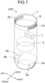
- FIG. 1 is a perspective view of the hand drying apparatus 100.
- FIG. 2 is a front view of the hand drying apparatus 100.
- FIG. 3 is a right side view of the hand drying apparatus 100.
- the hand drying apparatus 100 includes a housing 1, a blower 3, and nozzle parts 4a and 4b.
- the housing 1 defines a contour of the apparatus.
- the blower 3 is provided inside the housing 1.
- the nozzle parts 4a and 4b each eject air delivered from the blower 3, out of the housing 1 such that the ejected air fans out.
- the hand drying apparatus 100 also includes hand detection units 5a and 5b and a control unit 7.
- the hand detection units 5a and 5b detect insertion of a user's hands into outside spaces of the housing, toward which spaces the nozzle parts 4a and 4b eject the air.
- the control unit 7 controls the operation of the blower 3 on the basis of results of detection by the hand detection units 5a and 5b.
- a side near the user is defined as “front”
- a side far from the user is defined as “back”
- an upper side is defined as “top”
- a lower side is defined as “bottom”
- a right-hand side is defined as “right”
- a left-hand side is defined as "left”.
- the housing 1 has a vertically extending cylindrical outer contour, and has its back attached to a wall surface W.
- the housing 1 has a left-to-right width less than a breadth of the user's shoulders.
- the left-to-right width of the housing 1 can be, for example, less than or equal to 150 mm. Setting the left-to-right width of the housing 1 less than or equal to the specified value enables the user to bring the hands to the outside on the left and the right of the housing 1 without the hands touching the housing 1 when the user extends the hands forward, facing the housing 1.
- the housing 1 has a front-to-back width of more than or equal to 75 mm. This prevents the user' hands extended to the outside on the left and the right of the housing 1 from touching the wall surface W.
- Air intakes 2a and 2b through which ambient air is drawn into the housing 1 are provided in left and right sides of an upper part of the housing 1.
- An air passage inside the housing 1 extends from the air intakes 2a and 2b to the blower 3.
- an air filter 9 for preventing entry of dust or water droplets.
- the air filter 9 to be used include a resin net, a metal mesh, and a high-efficiency particulate air
- the air filter 9 is preferably disposed such that an air intake face of the air filter 9 is located above the air intakes 2a and 2b.
- the air filter 9 is disposed in this manner in order to prevent water droplets from falling onto or adhering to the air filter 9 even if the water droplets enter through the air intakes 2a and 2b.
- the blower 3 includes a motor and a turbofan or another fan rotated by the motor.
- the housing 1 has its lower part having the nozzle parts 4a and 4b provided at left and right side parts thereof for ejecting the air delivered from the blower 3, out of the housing 1 such that the ejected air fans out.
- the nozzle part 4a for the user's right hand is provided at the right side part of the housing 1
- the nozzle part 4b for the user's left hand is provided at the left side part of the housing 1.
- Each of the nozzle parts 4a and 4b includes an air outlet that is an elongate slit-shaped opening through which the inside of the housing communicates with the outside of the housing 1.
- the side parts of the housing 1 including the nozzle parts 4a and 4b have curved external surfaces that are convex in an outward direction of the housing 1.
- the air outlets of the nozzle parts 4a and 4b are flush with the external surfaces of the housing 1.
- the air outlets are in substantially arc-shapes between uppermost edges 41a, 41b of the air outlets and lowermost edges 42a, 42b of the air outlets, the arc-shapes being convex in the outward direction of the housing 1, relative to straight lines La, Lb interconnecting the uppermost edges 41a, 41b and the lowermost edges 42a, 42b.
- This shape allows each of the nozzle parts 4a, 4b to eject the air in the shape of a fan out of the housing 1 as indicated by a dotted line Fa or Fb in FIG. 2 .
- sheet-shaped airflows widening downstream are formed.
- the airflows supplied from the nozzle parts 4a and 4b form hand drying spaces outside the right and the left of the housing 1, and the hand drying spaces can dry the hands.
- each nozzle part 4a or 4b does not necessarily have to be flush with the external surface of the housing 1 as long as the air outlet is at least partially in the substantially arc-shape between the uppermost edge 41a or 41b and the lowermost edge 42a or 42b, the substantially arc-shape being convex in the outward direction of the housing 1, relative to the straight line La or Lb interconnecting the uppermost edge 41a or 41b and the lowermost edge 42a or 42b.
- the substantially arc-shaped portion does not necessarily have to be formed as a curved line (or a curved surface).
- the substantially arc-shaped portion may be formed as a combination of straight lines (or plane surfaces) or a combination of a straight line and a curved line (or a combination of a plane surface and a curved surface).
- the user who uses the hand drying apparatus 100 extends the hands in such a manner as to hold the hands over the left and right side parts of the housing 1, thus inserting the hands into the hand drying spaces.
- a direction in which fingers of the user's hands inserted into the hand drying spaces points is a forward, diagonally downward direction when viewed from the user, as indicated by arrow A in FIG. 3 .
- the air outlet of each nozzle part 4a or 4b extends generally orthogonally to the direction in which the fingers point.
- the air outlet of each nozzle part 4a or 4b has the shape of an oblique line extending diagonally from a front lower position of the nozzle part to a rear upper position of the nozzle part.
- the air outlet is close to the front as the air outlet extends downward.
- the slope of the air outlet of each nozzle part 4a or 4b provides an angle x in a range from 0 to 45° inclusive relative to a front-to-back direction.
- the airflow supplied from each nozzle part 4a or 4b is the sheet-shaped airflow spreading along a width of the user's hand, thereby enabling the user to efficiently remove water droplets by moving the hands back and forth.
- a length of the air outlet of each nozzle part 4a or 4b between the uppermost edge 41a or 41b and the lowermost edge 42a or 42b is set so that a width of the airflow at a location slightly away from the air outlet in the outward direction of the housing 1, i.e., a location where the user actually dries the hand is equal to or greater than the widthwise length of the user's hand.
- the airflow ejected from each nozzle part 4a or 4b widens downstream. In view of this widening of the ejected airflow, the length of the air outlet is less than the width of the airflow at the position where the user actually dries the hand.
- the width of the airflow at the position where the user actually dries the hand is about the same as the widthwise length of the user's hand, and the length of the air outlet extending from the uppermost edge 41a or 41b to the lowermost edge 42a or 42b can be less than the widthwise length of the user's hand. Consequently, the hand drying apparatus 100 can be smaller in size and easier to handle.
- the widthwise length of the user's hand is an average length of a hand of a male adult in a country where the hand drying apparatus 100 is used.
- Each nozzle part 4a or 4b is formed to eject the fan-shaped air within a downward range between a horizontal direction and a vertical direction. Specifically, assuming that the horizontal direction is defined as providing 0° and the vertical direction is defined as providing 90°, each of the nozzle parts 4a and 4b ejects the fan-shaped air in the range from 0° to 60° inclusive. In other words, each of the nozzle parts 4a and 4b ejects the air in the direction of 0° at the uppermost edge 41a or 41b of the air outlet and in the direction of 60° at the lowermost edge 42a or 42b, thus allowing air to be ejected from the entirety of the air outlet in the range from 0° to 60° inclusive.
- a transverse width of the air outlet of each nozzle part 4a or 4b can be, for example, less than or equal to 2 mm.
- an output of the blower 3 can be set so that the air is ejected from the air outlet at a velocity of, for example, more than or equal to 80 m/s. The water droplets on the user's hands can be effectively scraped off by the sheet-shaped airflows.
- the housing 1 includes, near the nozzle parts 4a and 4b, the hand detection units 5a and 5b that detect the insertion of the user's hands into the hand drying spaces formed by the nozzle parts 4a and 4b. Using a single or plural optical or capacitive sensors, each of the hand detection units 5a and 5b monitors whether or not the user's hand is inserted into the hand drying space and detects the insertion of the hand.
- the hand detection unit 5a is provided forwardly of the nozzle part 4a in the housing 1 and detects the insertion of the user's hand into the hand drying space set on the right of the housing 1.
- the hand detection unit 5b is provided forwardly of the nozzle part 4b in the housing 1 and detects the insertion of the user's hand into the hand drying space set on the left of the housing 1.
- the hand detection unit 5a is provided in front of and above the nozzle part 4a
- the hand detection unit 5b is provided in front of and above the nozzle part 4b.
- the control unit 7 controls the operation of the blower 3 on the basis of the results of detection by the hand detection units 5a and 5b to ensure that the air is ejected from the nozzle parts 4a and 4b when the hands are detected.
- the control unit 7 allows both the nozzle parts 4a and 4b to eject the air.
- the air may be ejected only from the nozzle part on the side where the hand has been detected.
- the control unit 7 is disposed inside or adjacent to the air passage disposed inside the housing 1 and extending from the air intakes 2a and 2b to the blower 3.
- the control unit 7 is cooled by an airflow in the air passage to thereby reduce an increase in temperature of the control unit 7.
- exhaust heat from the control unit 7 can be used to warm up the air ejected from the nozzle parts 4a and 4b.
- the hand detection units 5a and 5b detect the hands, and the control unit 7 activates the blower 3.
- the air around the housing 1 is drawn into the housing 1 through the air intakes 2a and 2b.
- the air drawn in flows into the blower 3 through the air filter 9, is pressurized by the blower 3, and is delivered to the nozzle parts 4a and 4b.
- the nozzle parts 4a and 4b eject the air delivered from the blower 3, out of the housing such that the ejected air fans out.
- the airflows supplied from the nozzle parts 4a and 4b strike the user's hands, thus blowing off the water droplets on the wet hands.
- the hand drying apparatus 100 includes the housing 1, the blower 3 provided inside the housing 1, and the nozzle parts 4a and 4b provided at the left and right side parts of the housing 1 when viewed from the user facing the housing 1, the nozzle parts 4a, 4b each ejecting the air delivered from the blower 3, out of the housing 1 such that the ejected air fans out.
- This enables the user to dry user's hands outside the left and the right of the housing 1. Since no structure between the user and the hands blocks a user's view, the user can dry the hands, checking the entire hands visually. Since the user can dry the entire hands checking the hands visually, the user can leave no part of the hands undried without the hands unintentionally touching the housing 1. As a result, it becomes possible to hygienically and efficiently dry the user's hand.
- FIG. 4 is a right side view of the hand drying apparatus 200.
- FIG. 5 is a front view of the hand drying apparatus 200.
- the hand drying apparatus 200 differs from that of the first embodiment in that a housing 201 has a hexahedral external form whose vertical and front-to-back lengths are substantially the same.
- the housing 201 of the hand drying apparatus 200 houses a control unit 207 and a blower 203, etc.
- the housing 201 has its lower part having nozzle parts 204a and 204b provided at left and right side parts thereof for ejecting air delivered from the blower 203, out of the housing 201 such that the ejected air fans out.
- Each of the nozzle parts 204a and 204b includes an air outlet that is an elongate slit-shaped opening through which the inside of the housing 201 communicates with the outside of the housing 201.
- the air outlets have lower portions located more inwardly away from an external face of the housing 201.
- the air outlets are in substantially arc-shapes between uppermost edges 241a, 241b of the air outlets and lowermost edge 242a, 242b of the air outlets, the arc-shapes being convex in an outward direction of the housing 201, relative to the straight lines La, Lb interconnecting the uppermost edges 241a, 241b and the lowermost edges 242a, 242b.
- the hand drying apparatus 200 also includes an air intake, an air filter, and a hand detection unit, among others. The hand drying apparatus 200 thus configured operates similarly to the hand drying apparatus 100.
- FIG. 6 is a right side view of the hand drying apparatus 300.
- the hand drying apparatus 300 differs from that of the first embodiment in that a housing 301 has a spherical external form.
- the housing 301 of the hand drying apparatus 300 houses a control unit 307 and a blower 303, etc.
- the housing 301 has its lower part having nozzle parts 304 provided at left and right side parts thereof for ejecting air delivered from the blower 303, out of the housing 301 such that the ejected air fans out.
- Each of the nozzle parts 304 is provided with an air outlet that is an elongate slit-shaped opening through which the inside of the housing 301 communicates with the outside of the housing 301.
- the air outlets are flush with an external surface of the housing 301.
- the air outlets are in substantially arc-shapes between uppermost edges of the air outlets and lowermost edges of the air outlets, the arc-shapes being convex in an outward direction of the housing 301, relative to straight lines interconnecting the uppermost edges and the lowermost edges.
- the hand drying apparatus 300 also includes an air intake, an air filter, and a hand detection unit, among others. The hand drying apparatus 300 thus configured operates similarly to the hand drying apparatus 100.
- the external form of the housing is cylindrical, hexahedral, or spherical in each of the above embodiments, the external form of the housing may be a prism, a semicylinder, a polyhedron other than the prism, a hemisphere, or any shape that is a complex combination of plane and curved surfaces.
- the air outlet of the nozzle part is the elongate slit-shaped opening in each of the above embodiments
- the air outlet of the nozzle part may be defined by a plurality of small openings arranged in a line.
- the air outlet of the nozzle part may be defined by plural slit-shaped openings or plural lines of small openings.
- the air outlet of the nozzle part may include a dividing wall for reinforcement, such as an elongate rib.
- the air outlet of the nozzle part in each of the above embodiments is of substantially uniform width from the uppermost edge to the lowermost edge
- the air outlet of the nozzle part can have a greater opening width at its upper part than an opening width at its lower part to provide an increased air quantity from the upper part. Consequently, when the user holds palms of the hands over the nozzle parts, thumbs, which tend to have much remaining water droplets because of their relatively great surface areas can be exposed to a greater air quantity than the other portions of the hands, which results in efficient hand drying.
- the housing includes the left and right nozzle parts in a bilaterally symmetric manner in each of the above embodiments, but does not necessarily have to include such nozzle parts. Only one of the right and left side parts of the housing may include the nozzle part.
- the left and right nozzle parts may be connected together at the front or the bottom of the housing. For example, the left and right nozzle parts may be connected to form one nozzle. A wider hand drying space with the left and right nozzle parts connected together can efficiently dry not only the hands but also arms.
- the nozzle part ejects air in the range from 0° to 60° inclusive in each of the above embodiments, this range may be changed as required.
- the range may be from 0° to 90° inclusive or from 0° to 45° inclusive.
- the range may be from 0° to 30° inclusive.
- the range may be from -30° to 30° inclusive or from -45° to 0° inclusive.
- the air intake is provided in the side of the housing's upper part in each of the above embodiments, the air intake may be provided in any position other than a top face of the housing. In that case, the air intake is disposed above the nozzle part to prevent water droplets from entering the housing through the air intake when the hand is dried near the nozzle part.
- the hand detection unit is provided forwardly of the nozzle part in the housing in each of the above embodiments, the hand detection unit does not necessarily have to be disposed in front of the nozzle part as long as the hand detection unit is disposed in such a position as to enable timely detection of the hand that approaches the hand drying space. While the hand detection units are two in number in the description of each of the above embodiments, one or at least three hand detection units may be provided.
- the housing is attached to the wall surface in each of the above embodiments, the housing may be disposed above a washstand including a washbowl.
- the air outlet of the nozzle part is substantially arc-shaped in each of the above embodiments, the air outlet does not necessarily have to be substantially arc-shaped in its entirety, from the uppermost edge to the lowermost edge, as long as the air outlet substantially has the substantially arc-shaped portion between the uppermost edge and the lowermost edge.
Landscapes
- Health & Medical Sciences (AREA)
- Public Health (AREA)
- Domestic Plumbing Installations (AREA)
- Bidet-Like Cleaning Device And Other Flush Toilet Accessories (AREA)
Abstract
Description
- The present disclosure relates to a hand drying apparatus that dries wet hands in a washroom, a toilet, or the like.
-
Patent Literature 1 discloses a hand drying apparatus that includes a hand drying chamber having an opening that allows a user to insert hands therethrough. As the user's hands are inserted into the hand drying chamber, air outlets provided in an upper part of the hand drying chamber ejects air toward the downward located hands. Patent Literature 2 discloses a hand dryer that includes nozzle sections configured to eject air downward. As a user's hands are inserted underneath the nozzle sections, the air is ejected toward the downward located hands. The hand dryer disclosed in Patent Literature 2 has the two nozzle sections that correspond to the left and right hands, respectively. Each of the nozzle sections spans a width of the user's open hand so that the air blows against an entire palm or back of each hand. -
- Patent Literature 1:
Japanese Patent Application Laid-open No. 2011-130944 - Patent Literature 2:
Japanese Patent Application Laid-open No. 2013-039379 - The above hand drying apparatus disclosed in
Patent Literature 1 requires the user to insert the hands under the air outlets in the hand drying chamber in drying the hands. This poses a problem of such a structure as the air outlets blocking a part of the user's view, which results in the user failing to dry the hand checking the entire hands visually. - The above hand dryer described in Patent Literature 2, also requires the user to insert the hands underneath the nozzle sections in drying the hands. This poses a problem of such a structure as the nozzle sections blocking a part of the user's view, which results in the user failing to dry the hands checking the entire hands visually.
- An object of the present disclosure is to provide a hand drying apparatus that enables a user to dry hands checking entire hands visually.
- A hand drying apparatus according to the present disclosure comprises: a housing; a blower provided inside the housing; and a nozzle part to eject air delivered from the blower, out of the housing such that the ejected air fans out, the nozzle part being provided at one of left and right side parts of the housing when viewed from a user facing the housing.
- The hand drying apparatus according to the present disclosure enables the user to dry the hands checking the entire hands visually.
-
-
FIG. 1 is a perspective view of a hand drying apparatus according to a first embodiment. -
FIG. 2 is a front view of the hand drying apparatus according to the first embodiment. -
FIG. 3 is a right side view of the hand drying apparatus according to the first embodiment. -
FIG. 4 is a right side view of a hand drying apparatus according to a second embodiment. -
FIG. 5 is a front view of the hand drying apparatus according to the second embodiment. -
FIG. 6 is a right side view of a hand drying apparatus according to a third embodiment. - A description is hereinafter made as to a
hand drying apparatus 100 according to a first embodiment.FIG. 1 is a perspective view of thehand drying apparatus 100.FIG. 2 is a front view of thehand drying apparatus 100.FIG. 3 is a right side view of thehand drying apparatus 100. As illustrated inFIGS. 1 to 3 , thehand drying apparatus 100 includes ahousing 1, ablower 3, andnozzle parts housing 1 defines a contour of the apparatus. Theblower 3 is provided inside thehousing 1. Thenozzle parts blower 3, out of thehousing 1 such that the ejected air fans out. Thehand drying apparatus 100 also includeshand detection units control unit 7. Thehand detection units nozzle parts control unit 7 controls the operation of theblower 3 on the basis of results of detection by thehand detection units - When viewed from the user who faces the
hand drying apparatus 100 according to the present disclosure, a side near the user is defined as "front", a side far from the user is defined as "back", an upper side is defined as "top", a lower side is defined as "bottom", a right-hand side is defined as "right", and a left-hand side is defined as "left". - The
housing 1 has a vertically extending cylindrical outer contour, and has its back attached to a wall surface W. Thehousing 1 has a left-to-right width less than a breadth of the user's shoulders. The left-to-right width of thehousing 1 can be, for example, less than or equal to 150 mm. Setting the left-to-right width of thehousing 1 less than or equal to the specified value enables the user to bring the hands to the outside on the left and the right of thehousing 1 without the hands touching thehousing 1 when the user extends the hands forward, facing thehousing 1. - The
housing 1 has a front-to-back width of more than or equal to 75 mm. This prevents the user' hands extended to the outside on the left and the right of thehousing 1 from touching the wall surface W. -
Air intakes housing 1 are provided in left and right sides of an upper part of thehousing 1. An air passage inside thehousing 1 extends from theair intakes blower 3. Provided in the air passage is an air filter 9 for preventing entry of dust or water droplets. Examples of the air filter 9 to be used include a resin net, a metal mesh, and a high-efficiency particulate air - (HEPA) filter. The air filter 9 is preferably disposed such that an air intake face of the air filter 9 is located above the
air intakes air intakes - The
blower 3 includes a motor and a turbofan or another fan rotated by the motor. Theblower 3, which has its operation controlled by thecontrol unit 7, pressurizes the air flowing in through the air filter 9 from theair intakes nozzle parts - The
housing 1 has its lower part having thenozzle parts blower 3, out of thehousing 1 such that the ejected air fans out. Thenozzle part 4a for the user's right hand is provided at the right side part of thehousing 1, and thenozzle part 4b for the user's left hand is provided at the left side part of thehousing 1. - Each of the
nozzle parts housing 1. The side parts of thehousing 1 including thenozzle parts housing 1. The air outlets of thenozzle parts housing 1. Thus, the air outlets are in substantially arc-shapes betweenuppermost edges lowermost edges housing 1, relative to straight lines La, Lb interconnecting theuppermost edges lowermost edges nozzle parts housing 1 as indicated by a dotted line Fa or Fb inFIG. 2 . In other words, sheet-shaped airflows widening downstream are formed. The airflows supplied from thenozzle parts housing 1, and the hand drying spaces can dry the hands. - The air outlet of each
nozzle part housing 1 as long as the air outlet is at least partially in the substantially arc-shape between theuppermost edge lowermost edge housing 1, relative to the straight line La or Lb interconnecting theuppermost edge lowermost edge - The user who uses the
hand drying apparatus 100 extends the hands in such a manner as to hold the hands over the left and right side parts of thehousing 1, thus inserting the hands into the hand drying spaces. A direction in which fingers of the user's hands inserted into the hand drying spaces points is a forward, diagonally downward direction when viewed from the user, as indicated by arrow A inFIG. 3 . In view of this, the air outlet of eachnozzle part housing 1 is viewed from the side, the air outlet of eachnozzle part FIG. 3 , the slope of the air outlet of eachnozzle part nozzle part - A length of the air outlet of each
nozzle part uppermost edge lowermost edge housing 1, i.e., a location where the user actually dries the hand is equal to or greater than the widthwise length of the user's hand. Specifically, the airflow ejected from eachnozzle part uppermost edge lowermost edge hand drying apparatus 100 can be smaller in size and easier to handle. The widthwise length of the user's hand is an average length of a hand of a male adult in a country where thehand drying apparatus 100 is used. - Each
nozzle part nozzle parts nozzle parts uppermost edge lowermost edge - A transverse width of the air outlet of each
nozzle part blower 3 can be set so that the air is ejected from the air outlet at a velocity of, for example, more than or equal to 80 m/s. The water droplets on the user's hands can be effectively scraped off by the sheet-shaped airflows. - The
housing 1 includes, near thenozzle parts hand detection units nozzle parts hand detection units hand detection unit 5a is provided forwardly of thenozzle part 4a in thehousing 1 and detects the insertion of the user's hand into the hand drying space set on the right of thehousing 1. Thehand detection unit 5b is provided forwardly of thenozzle part 4b in thehousing 1 and detects the insertion of the user's hand into the hand drying space set on the left of thehousing 1. In the example illustrated inFIGS. 1 to 3 , thehand detection unit 5a is provided in front of and above thenozzle part 4a, and thehand detection unit 5b is provided in front of and above thenozzle part 4b. - The
control unit 7 controls the operation of theblower 3 on the basis of the results of detection by thehand detection units nozzle parts hand detection units control unit 7 allows both thenozzle parts hand detection units - The
control unit 7 is disposed inside or adjacent to the air passage disposed inside thehousing 1 and extending from theair intakes blower 3. When thehand drying apparatus 100 is in operation, thus, thecontrol unit 7 is cooled by an airflow in the air passage to thereby reduce an increase in temperature of thecontrol unit 7. Moreover, exhaust heat from thecontrol unit 7 can be used to warm up the air ejected from thenozzle parts - A description is made as to how the
hand drying apparatus 100 operates. When the user puts the hands in the hand drying spaces formed outside the right and the left of the housing, thehand detection units control unit 7 activates theblower 3. The air around thehousing 1 is drawn into thehousing 1 through theair intakes blower 3 through the air filter 9, is pressurized by theblower 3, and is delivered to thenozzle parts nozzle parts blower 3, out of the housing such that the ejected air fans out. The airflows supplied from thenozzle parts - As described above, the
hand drying apparatus 100 includes thehousing 1, theblower 3 provided inside thehousing 1, and thenozzle parts housing 1 when viewed from the user facing thehousing 1, thenozzle parts blower 3, out of thehousing 1 such that the ejected air fans out. This enables the user to dry user's hands outside the left and the right of thehousing 1. Since no structure between the user and the hands blocks a user's view, the user can dry the hands, checking the entire hands visually. Since the user can dry the entire hands checking the hands visually, the user can leave no part of the hands undried without the hands unintentionally touching thehousing 1. As a result, it becomes possible to hygienically and efficiently dry the user's hand. - A description is hereinafter made as to a
hand drying apparatus 200 according to a second embodiment.FIG. 4 is a right side view of thehand drying apparatus 200.FIG. 5 is a front view of thehand drying apparatus 200. Thehand drying apparatus 200 differs from that of the first embodiment in that ahousing 201 has a hexahedral external form whose vertical and front-to-back lengths are substantially the same. Thehousing 201 of thehand drying apparatus 200 houses acontrol unit 207 and ablower 203, etc. Thehousing 201 has its lower part havingnozzle parts blower 203, out of thehousing 201 such that the ejected air fans out. Each of thenozzle parts housing 201 communicates with the outside of thehousing 201. As illustrated inFIG. 5 , the air outlets have lower portions located more inwardly away from an external face of thehousing 201. The air outlets are in substantially arc-shapes betweenuppermost edges lowermost edge housing 201, relative to the straight lines La, Lb interconnecting theuppermost edges lowermost edges hand drying apparatus 200 also includes an air intake, an air filter, and a hand detection unit, among others. Thehand drying apparatus 200 thus configured operates similarly to thehand drying apparatus 100. - A description is hereinafter made as to a
hand drying apparatus 300 according to a third embodiment.FIG. 6 is a right side view of thehand drying apparatus 300. Thehand drying apparatus 300 differs from that of the first embodiment in that ahousing 301 has a spherical external form. Thehousing 301 of thehand drying apparatus 300 houses acontrol unit 307 and ablower 303, etc. Thehousing 301 has its lower part havingnozzle parts 304 provided at left and right side parts thereof for ejecting air delivered from theblower 303, out of thehousing 301 such that the ejected air fans out. Each of thenozzle parts 304 is provided with an air outlet that is an elongate slit-shaped opening through which the inside of thehousing 301 communicates with the outside of thehousing 301. The air outlets are flush with an external surface of thehousing 301. Thus, the air outlets are in substantially arc-shapes between uppermost edges of the air outlets and lowermost edges of the air outlets, the arc-shapes being convex in an outward direction of thehousing 301, relative to straight lines interconnecting the uppermost edges and the lowermost edges. Thehand drying apparatus 300 also includes an air intake, an air filter, and a hand detection unit, among others. Thehand drying apparatus 300 thus configured operates similarly to thehand drying apparatus 100. - While the external form of the housing is cylindrical, hexahedral, or spherical in each of the above embodiments, the external form of the housing may be a prism, a semicylinder, a polyhedron other than the prism, a hemisphere, or any shape that is a complex combination of plane and curved surfaces.
- While the air outlet of the nozzle part is the elongate slit-shaped opening in each of the above embodiments, the air outlet of the nozzle part may be defined by a plurality of small openings arranged in a line. The air outlet of the nozzle part may be defined by plural slit-shaped openings or plural lines of small openings. The air outlet of the nozzle part may include a dividing wall for reinforcement, such as an elongate rib.
- While the above air outlet of the nozzle part in each of the above embodiments is of substantially uniform width from the uppermost edge to the lowermost edge, the air outlet of the nozzle part can have a greater opening width at its upper part than an opening width at its lower part to provide an increased air quantity from the upper part. Consequently, when the user holds palms of the hands over the nozzle parts, thumbs, which tend to have much remaining water droplets because of their relatively great surface areas can be exposed to a greater air quantity than the other portions of the hands, which results in efficient hand drying.
- The housing includes the left and right nozzle parts in a bilaterally symmetric manner in each of the above embodiments, but does not necessarily have to include such nozzle parts. Only one of the right and left side parts of the housing may include the nozzle part. The left and right nozzle parts may be connected together at the front or the bottom of the housing. For example, the left and right nozzle parts may be connected to form one nozzle. A wider hand drying space with the left and right nozzle parts connected together can efficiently dry not only the hands but also arms.
- While the nozzle part ejects air in the range from 0° to 60° inclusive in each of the above embodiments, this range may be changed as required. For example, the range may be from 0° to 90° inclusive or from 0° to 45° inclusive. The range may be from 0° to 30° inclusive. The range may be from -30° to 30° inclusive or from -45° to 0° inclusive.
- While the air intake is provided in the side of the housing's upper part in each of the above embodiments, the air intake may be provided in any position other than a top face of the housing. In that case, the air intake is disposed above the nozzle part to prevent water droplets from entering the housing through the air intake when the hand is dried near the nozzle part.
- While the hand detection unit is provided forwardly of the nozzle part in the housing in each of the above embodiments, the hand detection unit does not necessarily have to be disposed in front of the nozzle part as long as the hand detection unit is disposed in such a position as to enable timely detection of the hand that approaches the hand drying space. While the hand detection units are two in number in the description of each of the above embodiments, one or at least three hand detection units may be provided.
- While the housing is attached to the wall surface in each of the above embodiments, the housing may be disposed above a washstand including a washbowl.
- While the described air outlet of the nozzle part is substantially arc-shaped in each of the above embodiments, the air outlet does not necessarily have to be substantially arc-shaped in its entirety, from the uppermost edge to the lowermost edge, as long as the air outlet substantially has the substantially arc-shaped portion between the uppermost edge and the lowermost edge.
- 1, 201, 301 housing; 2a, 2b air intake; 3, 203, 303 blower; 7, 207, 307 control unit; 9 air filter; 4a, 4b, 204a, 204b, 304 nozzle part; 5a, 5b hand detection unit; 100, 200, 300 hand drying apparatus; W wall surface.
Claims (14)
- A hand drying apparatus comprising:a housing;a blower provided inside the housing; anda nozzle part to eject air delivered from the blower, out of the housing such that the ejected air fans out, the nozzle part being provided at one of left and right side parts of the housing when viewed from a user facing the housing.
- The hand drying apparatus according to claim 1, wherein the nozzle part ejects the air in a shape of a fan downwardly in a range defined between a horizontal direction and a vertical direction.
- The hand drying apparatus according to claim 2, wherein the nozzle part ejects the air in the shape of the fan in a range from 0° to 60° inclusive when the horizontal direction is defined as providing 0° and the vertical direction is defined as providing 90°.
- The hand drying apparatus according to claim 2, wherein the nozzle part ejects the air in the shape of the fan in a range from 0° to 30° inclusive when the horizontal direction is defined as providing 0° and the vertical direction is defined as providing 90°.
- The hand drying apparatus according to any one of claims 1 to 4, whereinthe nozzle part includes an air outlet that is an opening through which an inside of the housing communicates with an outside of the housing, andthe air outlet includes a substantially arc-shaped portion between an uppermost edge of the air outlet and a lowermost edge of the air outlet, the arc-shaped portion being convex in an outward direction of the housing, relative to a straight line interconnecting the uppermost edge and the lowermost edge.
- The hand drying apparatus according to claim 5, wherein the air outlet has a shorter length extending from the uppermost edge to the lowermost edge than a widthwise length of a hand of a user.
- The hand drying apparatus according to claim 5 or 6, wherein the air outlet is close to a front of the housing as the air outlet extends downward, the front of the housing being near the user when viewed from the user facing the housing.
- The hand drying apparatus according to any one of claims 5 to 7, wherein the air outlet is flush with an external surface of the housing.
- The hand drying apparatus according to any one of claims 5 to 8, wherein the air outlet has a greater opening width at an upper part of the air outlet than an opening width at a lower part of the air outlet.
- The hand drying apparatus according to any one of claims 1 to 9, further comprisinga hand detection means to detect an insertion of an user's hand into an outside space of the housing, toward which space the nozzle part ejects the air, whereinthe hand detection means is provided in front of the nozzle part in the housing, the front being near the user when viewed from the user facing the housing.
- The hand drying apparatus according to any one of claims 1 to 10, wherein the housing is in a shape of a cylinder, a prism, a semicylinder, a polyhedron other than the prism, a sphere, or a hemisphere.
- The hand drying apparatus according to any one of claims 1 to 11, wherein the housing is in a shape of a vertically extending pillar and the nozzle part is provided at a lower part of the housing.
- The hand drying apparatus according to any one of claims 1 to 12, wherein the housing includes the nozzle part at each of the left and right side parts of the housing.
- The hand drying apparatus according to any one of claims 1 to 13, wherein the housing is disposed above a washstand including a washbowl.
Applications Claiming Priority (1)
| Application Number | Priority Date | Filing Date | Title |
|---|---|---|---|
| PCT/JP2020/044301 WO2022113291A1 (en) | 2020-11-27 | 2020-11-27 | Hand-drying device |
Publications (2)
| Publication Number | Publication Date |
|---|---|
| EP4252603A1 true EP4252603A1 (en) | 2023-10-04 |
| EP4252603A4 EP4252603A4 (en) | 2024-01-03 |
Family
ID=81755428
Family Applications (1)
| Application Number | Title | Priority Date | Filing Date |
|---|---|---|---|
| EP20963555.6A Pending EP4252603A4 (en) | 2020-11-27 | 2020-11-27 | HAND DRYING DEVICE |
Country Status (5)
| Country | Link |
|---|---|
| US (1) | US20230337871A1 (en) |
| EP (1) | EP4252603A4 (en) |
| JP (1) | JP7383177B2 (en) |
| CN (1) | CN116490105A (en) |
| WO (1) | WO2022113291A1 (en) |
Cited By (2)
| Publication number | Priority date | Publication date | Assignee | Title |
|---|---|---|---|---|
| US20230337871A1 (en) * | 2020-11-27 | 2023-10-26 | Mitsubishi Electric Corporation | Hand drying apparatus |
| US20230371759A1 (en) * | 2020-11-27 | 2023-11-23 | Mitsubishi Electric Corporation | Hand dryer |
Families Citing this family (1)
| Publication number | Priority date | Publication date | Assignee | Title |
|---|---|---|---|---|
| WO2024024057A1 (en) * | 2022-07-28 | 2024-02-01 | 三菱電機株式会社 | Hand dryer |
Family Cites Families (26)
| Publication number | Priority date | Publication date | Assignee | Title |
|---|---|---|---|---|
| FR741741A (en) * | 1933-02-18 | |||
| US2853591A (en) * | 1955-12-15 | 1958-09-23 | American Dryer Corp | Electric hand dryer |
| JP3120165B2 (en) * | 1992-08-03 | 2000-12-25 | 九州日立マクセル株式会社 | Dryer |
| US6038786A (en) * | 1998-04-16 | 2000-03-21 | Excel Dryer Inc. | Hand dryer |
| JP2005278979A (en) | 2004-03-30 | 2005-10-13 | Matsushita Electric Ind Co Ltd | Hand dryer |
| WO2005110176A1 (en) * | 2004-05-19 | 2005-11-24 | Toto Ltd. | Hand drying apparatus |
| GB0515749D0 (en) * | 2005-07-30 | 2005-09-07 | Dyson Technology Ltd | Drying apparatus |
| US7774953B1 (en) * | 2007-05-25 | 2010-08-17 | Duran Napoli I | Athlete hand drying system |
| JP4474483B1 (en) * | 2009-02-06 | 2010-06-02 | シャープ株式会社 | Hand dryer |
| WO2010109661A1 (en) * | 2009-03-27 | 2010-09-30 | 三菱電機株式会社 | Hand dryer |
| JP5659401B2 (en) | 2009-12-25 | 2015-01-28 | パナソニックIpマネジメント株式会社 | Hand dryer |
| US20120260418A1 (en) * | 2011-04-18 | 2012-10-18 | Rundberg Michelle L | Lavatory System with Overflow Prevention and Other Features |
| US9267736B2 (en) * | 2011-04-18 | 2016-02-23 | Bradley Fixtures Corporation | Hand dryer with point of ingress dependent air delay and filter sensor |
| GB201114181D0 (en) | 2011-08-17 | 2011-10-05 | Dyson Technology Ltd | A hand dryer |
| US8813383B2 (en) * | 2012-03-06 | 2014-08-26 | Hokwang Industries Co., Ltd. | Watermark-free hand dryer |
| DE102015119446B3 (en) * | 2015-11-11 | 2017-03-02 | Hochschule Für Angewandte Wissenschaft Und Kunst Hildesheim/Holzminden/Göttingen | Method and device for drying and plasma-assisted disinfection of hands |
| CN205136778U (en) | 2015-12-06 | 2016-04-06 | 曹卫国 | Water tap |
| CN105615757A (en) * | 2016-01-26 | 2016-06-01 | 美的集团股份有限公司 | Hand drier |
| JP6552749B2 (en) * | 2016-08-26 | 2019-07-31 | 三菱電機株式会社 | Hand dryer |
| GB2562234B (en) * | 2017-05-08 | 2021-04-07 | Dyson Technology Ltd | A hand dryer |
| US10398793B2 (en) * | 2017-05-23 | 2019-09-03 | Alva Foster | Hand sanitizing assembly |
| US10722083B2 (en) * | 2017-10-03 | 2020-07-28 | Thunderhill Investments, LLC | Sanitary forced-air hand dryer |
| JP6761439B2 (en) | 2018-03-30 | 2020-09-23 | コイト電工株式会社 | A hand drying device and a washbasin equipped with the hand drying device |
| CN108606700A (en) * | 2018-06-04 | 2018-10-02 | 厦门建霖健康家居股份有限公司 | A kind of hand dryer and the hand basin with hand dryer |
| WO2022113291A1 (en) * | 2020-11-27 | 2022-06-02 | 三菱電機株式会社 | Hand-drying device |
| WO2022113292A1 (en) * | 2020-11-27 | 2022-06-02 | 三菱電機株式会社 | Hand drying device |
-
2020
- 2020-11-27 WO PCT/JP2020/044301 patent/WO2022113291A1/en not_active Ceased
- 2020-11-27 EP EP20963555.6A patent/EP4252603A4/en active Pending
- 2020-11-27 JP JP2022564954A patent/JP7383177B2/en active Active
- 2020-11-27 CN CN202080107301.8A patent/CN116490105A/en not_active Withdrawn
- 2020-11-27 US US18/246,188 patent/US20230337871A1/en active Pending
Cited By (2)
| Publication number | Priority date | Publication date | Assignee | Title |
|---|---|---|---|---|
| US20230337871A1 (en) * | 2020-11-27 | 2023-10-26 | Mitsubishi Electric Corporation | Hand drying apparatus |
| US20230371759A1 (en) * | 2020-11-27 | 2023-11-23 | Mitsubishi Electric Corporation | Hand dryer |
Also Published As
| Publication number | Publication date |
|---|---|
| CN116490105A (en) | 2023-07-25 |
| WO2022113291A1 (en) | 2022-06-02 |
| US20230337871A1 (en) | 2023-10-26 |
| JP7383177B2 (en) | 2023-11-17 |
| JPWO2022113291A1 (en) | 2022-06-02 |
| EP4252603A4 (en) | 2024-01-03 |
Similar Documents
| Publication | Publication Date | Title |
|---|---|---|
| EP4252603A1 (en) | Hand-drying device | |
| EP2744380B1 (en) | A hand dryer | |
| US7946055B2 (en) | Dryer | |
| EP2744381B1 (en) | A hand dryer | |
| US8490291B2 (en) | Dryer | |
| US8341853B2 (en) | Drying apparatus | |
| US8347521B2 (en) | Drying apparatus | |
| CN102325488B (en) | hand dryer | |
| US20100154239A1 (en) | Drying apparatus | |
| US9743814B2 (en) | Hand dryer | |
| US20080301970A1 (en) | Drying Apparatus | |
| JP6781732B2 (en) | Hand dryer | |
| TW201031374A (en) | Hand dryer | |
| KR20130032374A (en) | Hand dryer device | |
| US20080216344A1 (en) | Drying Apparatus | |
| CA2617079C (en) | Dryer | |
| AU2006274713B2 (en) | Drying apparatus | |
| CN104684448B (en) | Hand drying device |
Legal Events
| Date | Code | Title | Description |
|---|---|---|---|
| STAA | Information on the status of an ep patent application or granted ep patent |
Free format text: STATUS: THE INTERNATIONAL PUBLICATION HAS BEEN MADE |
|
| PUAI | Public reference made under article 153(3) epc to a published international application that has entered the european phase |
Free format text: ORIGINAL CODE: 0009012 |
|
| STAA | Information on the status of an ep patent application or granted ep patent |
Free format text: STATUS: REQUEST FOR EXAMINATION WAS MADE |
|
| 17P | Request for examination filed |
Effective date: 20230421 |
|
| AK | Designated contracting states |
Kind code of ref document: A1 Designated state(s): AL AT BE BG CH CY CZ DE DK EE ES FI FR GB GR HR HU IE IS IT LI LT LU LV MC MK MT NL NO PL PT RO RS SE SI SK SM TR |
|
| A4 | Supplementary search report drawn up and despatched |
Effective date: 20231201 |
|
| RIC1 | Information provided on ipc code assigned before grant |
Ipc: A47K 10/48 20060101AFI20231127BHEP |
|
| DAV | Request for validation of the european patent (deleted) | ||
| DAX | Request for extension of the european patent (deleted) |