EP4252562A1 - Atomiser and electronic atomising apparatus - Google Patents
Atomiser and electronic atomising apparatus Download PDFInfo
- Publication number
- EP4252562A1 EP4252562A1 EP21896859.2A EP21896859A EP4252562A1 EP 4252562 A1 EP4252562 A1 EP 4252562A1 EP 21896859 A EP21896859 A EP 21896859A EP 4252562 A1 EP4252562 A1 EP 4252562A1
- Authority
- EP
- European Patent Office
- Prior art keywords
- storage cavity
- air
- liquid storage
- air channel
- holder
- Prior art date
- Legal status (The legal status is an assumption and is not a legal conclusion. Google has not performed a legal analysis and makes no representation as to the accuracy of the status listed.)
- Pending
Links
Images




Classifications
-
- A—HUMAN NECESSITIES
- A24—TOBACCO; CIGARS; CIGARETTES; SIMULATED SMOKING DEVICES; SMOKERS' REQUISITES
- A24F—SMOKERS' REQUISITES; MATCH BOXES; SIMULATED SMOKING DEVICES
- A24F40/00—Electrically operated smoking devices; Component parts thereof; Manufacture thereof; Maintenance or testing thereof; Charging means specially adapted therefor
- A24F40/40—Constructional details, e.g. connection of cartridges and battery parts
- A24F40/48—Fluid transfer means, e.g. pumps
- A24F40/485—Valves; Apertures
-
- A—HUMAN NECESSITIES
- A24—TOBACCO; CIGARS; CIGARETTES; SIMULATED SMOKING DEVICES; SMOKERS' REQUISITES
- A24F—SMOKERS' REQUISITES; MATCH BOXES; SIMULATED SMOKING DEVICES
- A24F40/00—Electrically operated smoking devices; Component parts thereof; Manufacture thereof; Maintenance or testing thereof; Charging means specially adapted therefor
- A24F40/10—Devices using liquid inhalable precursors
-
- A—HUMAN NECESSITIES
- A24—TOBACCO; CIGARS; CIGARETTES; SIMULATED SMOKING DEVICES; SMOKERS' REQUISITES
- A24F—SMOKERS' REQUISITES; MATCH BOXES; SIMULATED SMOKING DEVICES
- A24F40/00—Electrically operated smoking devices; Component parts thereof; Manufacture thereof; Maintenance or testing thereof; Charging means specially adapted therefor
- A24F40/40—Constructional details, e.g. connection of cartridges and battery parts
-
- A—HUMAN NECESSITIES
- A24—TOBACCO; CIGARS; CIGARETTES; SIMULATED SMOKING DEVICES; SMOKERS' REQUISITES
- A24F—SMOKERS' REQUISITES; MATCH BOXES; SIMULATED SMOKING DEVICES
- A24F40/00—Electrically operated smoking devices; Component parts thereof; Manufacture thereof; Maintenance or testing thereof; Charging means specially adapted therefor
- A24F40/40—Constructional details, e.g. connection of cartridges and battery parts
- A24F40/42—Cartridges or containers for inhalable precursors
Definitions
- Embodiments of this application relate to the field of electronic vaporization technologies, and in particular, to a vaporizer and an electronic vaporization device.
- aerosol-providing articles for example, electronic vaporization devices.
- the devices generally include e-liquid.
- the e-liquid is heated to be vaporized, to generate an inhalable vapor or aerosol.
- the e-liquid may include nicotine and/or a fragrance composite and/or an aerosol-generation article (for example, glycerol).
- an existing electronic vaporization device generally includes a porous ceramic body that has a large amount of micropores inside and is configured to absorb and transfer the e-liquid, and a heating element is arranged on a surface of the porous ceramic body to heat and vaporize the absorbed e-liquid.
- micropores in the porous body are used as channels for the e-liquid to infiltrate and flow to a vaporization surface, and also used as air exchange channels for air to enter a liquid storage cavity from the outside to serve as a supplement to maintain balance of the air pressure in the liquid storage cavity after the e-liquid in the liquid storage cavity is consumed, so that bubbles are generated in the porous ceramic body when the e-liquid is heated, vaporized, and consumed, and then the bubbles emerge from a liquid absorbing surface and then enter the liquid storage cavity.
- the liquid storage cavity is gradually in a negative pressure state, preventing fluid transfer to a certain extent, so that the e-liquid is less conveyed to the vaporization surface through the micropore channels of the porous ceramic body for vaporization.
- the existing electronic vaporization device when the existing electronic vaporization device is in a use state of continuous inhaling, the air outside the liquid storage cavity is difficult to pass through the micropore channels of the porous ceramic body to enter the liquid storage cavity in a short time, slowing down the speed of transferring the e-liquid to the vaporization surface, and insufficient e-liquid supplied to the heating element causes an excessive temperature of the heating element, resulting in decomposition and volatilization of the e-liquid components to generate harmful substances such as formaldehyde.
- An embodiment of this application provides a vaporizer, configured to vaporize a liquid substrate to generate an aerosol for inhaling, including: a liquid storage cavity configured to store a liquid substrate; and further including:
- the free end of the blocking part is close to the edge position of the end wall of the seal element, and the connection end is more distant from the edge position of the end wall, so that in an assembly process, friction or deformation tension suffered by the edge position is separated by the slit defining the free end and has no impact on the connection end of the blocking part, thereby preventing the connection end from opening the first air channel due to deformation.
- An embodiment of this application further provides a vaporizer, configured to vaporize a liquid substrate to generate an aerosol for inhaling, including: a liquid storage cavity configured to store a liquid substrate; and further including:
- the vaporizer can relieve the negative pressure in the liquid storage cavity, and the free end of the blocking part extends away from the center of the seal element, so that the first air channel is not opened due to deformation caused by friction in an assembly process.
- the seal element includes a slit or groove partially surrounding the blocking part, and the blocking part is defined by the slit or groove.
- the slit or groove is constructed to bend toward the center of the seal element.
- the blocking part is constructed to extend along a cross section direction of the vaporizer.
- a recessed structure is provided on a surface of the blocking part that is toward the holder, and the recessed structure is configured to reduce a thickness and strength of the blocking part, so that the blocking part is more susceptible to bending or deformation.
- an inner diameter of the first air channel at least partially gradually decreases along a direction close to the air outlet end.
- the inner diameter of the first air channel at least partially decreases in a step-shaped manner along the direction close to the air outlet end.
- the holder is provided with a protruding edge surrounding the air outlet end of the first air channel, and the blocking part is constructed to abut the protruding edge, to seal the air outlet end.
- the holder at least partially defines a second air channel, to provide a second flowing path for air to enter the liquid storage cavity, and a porous body material is arranged in the second air channel.
- the seal element is provided with a through hole opposite to the second air channel, and air in the second air channel enters the liquid storage cavity through the through hole.
- the vaporizer further includes:
- an air pressure at an air inlet end of the first air channel is the same as an atmospheric pressure.
- Another embodiment of this application further provides a vaporizer, configured to vaporize a liquid substrate to generate an aerosol for inhaling, including: a liquid storage cavity configured to store a liquid substrate; and further including:
- the seal element is provided with a through hole opposite to the air channel, and air in the air channel enters the liquid storage cavity through the through hole.
- a pore size of the through hole is less than an inner diameter of the air channel.
- the porous body material is located at a position close to an air outlet end of the air channel.
- the vaporizer further includes:
- an air pressure at an air inlet end of the air channel is the same as an atmospheric pressure.
- the air channel includes a hole partially extending in the holder, and a groove partially located on an outer wall of the holder.
- the air channel is always open, and the porous body material is arranged to ensure air flowing into the liquid storage cavity to serve as a supplement to relieve the negative pressure in the liquid storage cavity and prevent liquid from seeping out.
- An embodiment of this application further provides an electronic vaporization device, including a vaporizer configured to vaporize a liquid substrate to generate an aerosol, and a power supply assembly configured to supply power to the vaporizer.
- the vaporizer includes the vaporizer described above.
- a construction of the device includes: a vaporizer 100, configured to store a liquid substrate and vaporize the liquid substrate to generate an aerosol, and a power supply assembly 200, configured to supply power to the vaporizer 100.
- the power supply assembly 200 includes: a receiving cavity 270, arranged on an end along a longitudinal direction and configured to receive and accommodate at least a part of the vaporizer 100; and a first electrical contact 230, at least partially exposed on a surface of the receiving cavity 270, configured to be electrically connected to the vaporizer 100 to supply power to the vaporizer 100 when at least a part of the vaporizer 100 is received and accommodated in the power supply assembly 200.
- a second electrical contact 21 is arranged on an end portion of the vaporizer 100 that is opposite to the power supply assembly 200 along the longitudinal direction, so that when the at least a part of the vaporizer 100 is received in the receiving cavity 270, the second electrical contact 21 becomes conductive through being in contact with and abutting the first electrical contact 230.
- a seal member 260 is arranged in the power supply assembly 200, and at least a part of an internal space of the power supply assembly 200 is separated by the seal member 260 to form the receiving cavity 270.
- the seal member 260 is configured to extend along a cross section direction of the power supply assembly 200, and is prepared by a flexible material, to prevent the liquid substrate seeping from the vaporizer 100 to the receiving cavity 270 from flowing to components such as a controller 220 and a sensor 250 inside the power supply assembly 200.
- the power supply assembly 200 further includes: a battery cell 210, close to another end relative to the receiving cavity 270 along the longitudinal direction for supplying power; and a controller 220, arranged between the battery cell 210 and an accommodating cavity, and operably guiding a current between the battery cell 210 and the first electrical contact 230.
- the power supply assembly 200 includes a sensor 250, configured to sense an inhalation airflow generated by the vaporizer 100 during inhalation, so that the controller 220 controls, based on a detection signal of the sensor 250, the battery cell 210 to output a current to the vaporizer 100.
- a charging interface 240 is arranged on another end of the power supply assembly 200 that is opposite to the receiving cavity 270, and is configured to charge the battery cell 210 through a connection with an external charging device.
- FIG. 2 to FIG. 5 show the structure of the vaporizer 100 in FIG. 1 according to a preferred embodiment.
- the vaporizer 100 includes:
- the second electrical contact 21 penetrates from outside of the end cap 20 into the main housing 10 and is at least partially exposed outside of the end cap 20, making it convenient to be conductively connected to the power supply assembly 200.
- an inner structure of the vaporizer 100 includes:
- the heating element 320 is formed on the vaporization surface of the liquid guide element 310 in a manner of mounting, printing, deposition, or the like.
- the heating element 320 may be made of a material such as stainless steel, nickel chromium alloy, iron chromium aluminum alloy, or metal titanium.
- the heating element 320 is a conductive trajectory in a winding or circuitous pattern.
- a support base 41 and a silicone bearing element 42 that is located in the support base 41 and is arranged opposite to the vaporization surface of the liquid guide element 310 are arranged between the vaporization assembly 30 and the end cap 20.
- the bearing element 42 and the vaporization surface of the liquid guide element 310 jointly define a vaporization chamber for accommodating the released aerosol.
- the bearing element 42 is opposite to the vaporization surface, to receive an aerosol condensate in the vaporization chamber and a liquid substrate effusing or seeping from the vaporization surface.
- the main housing 10 is internally provided with:
- the silicone sleeve 50 has a first accommodating space 51, and the liquid guide element 310 is accommodated and supported in the first accommodating space 51; and the rigid holder 60 has a second accommodating space 61, and the silicone sleeve 50 and the liquid guide element 310 are entirely assembled in the second accommodating space 61.
- the seal element 80 is provided with a first liquid guide hole 81
- the rigid holder 60 is provided with a second liquid guide hole 62
- the silicone sleeve 50 is provided with a third liquid guide hole 52.
- the liquid substrate in the liquid storage cavity 12 flows to the liquid guide element 310 and is absorbed, as shown by an arrow R1 in FIG. 4 and FIG. 5 , and finally is vaporized on the vaporization surface of the liquid guide element 310 and released into the vaporization chamber.
- the vaporization chamber defined by the silicone bearing element 42 and the liquid guide element 310 is in communication with an air inlet hole 22 provided on the end cap 20.
- the seal element 80 is provided with a first insertion hole 82 for inserting the aerosol output pipe 11.
- the rigid holder 60 is provided with a second insertion hole 66 opposite to the first insertion hole 82 and an output channel 63 located on a side of a thickness direction. An airflow path during inhalation is shown by an arrow R2 in FIG. 3 .
- the external air enters the vaporization chamber through the air inlet hole 22 on the end cap 20, and then carries the generated aerosol to be outputted from the output channel 63 to the aerosol output pipe 11 connected to the second insertion hole 66, until it is inhaled from the inhalation opening A.
- the rigid holder 60 is provided with a first air channel 64 and a second air channel 65.
- the first air channel 64 and the second air channel 65 are both configured to supplement air to the liquid storage cavity 12.
- the first air channel 64 penetrates the rigid holder 60 along the longitudinal direction
- the second air channel 65 is formed by a space such as a groove or an opening on an outer side wall of the rigid holder 60 along a width direction.
- first air channel 64 and the second air channel 65 may not be provided simultaneously, and only one of the two channels may be implemented.
- the seal element 80 is provided with a blocking part 83 configured to block and seal an air outlet end of the first air channel 64.
- the blocking part 83 is formed by surrounding a U-shaped groove or slit 831, so that the blocking part 83 and other parts of the seal element 80 are suspended.
- the blocking part 83 blocks the air outlet end of the first air channel 64.
- the blocking part 83 can bend or warp into the liquid storage cavity 12 in response to the negative pressure change, as shown in FIG. 7 , so that the air outlet end of the first air channel 64 is opened, and the external air enters the liquid storage cavity 12 to relieve the negative pressure.
- the blocking part 83 of the seal element 80 is constructed to extend along the width direction.
- the blocking part 83 may be at an included angle with the width direction. In a preferred embodiment, the included angle may range from -90 to 90 degrees.
- the seal element 80 is in a shape with an end wall 810, and a side wall 820 extending from the end wall 810 and wrapping the holder 60.
- the blocking part 83 is formed on the end wall 810.
- the seal element 80 has an edge position 85 closest to a front free end 831 of the blocking part 83.
- the edge position 85 is an edge position along the width direction that is close to the free end 831.
- a distance d1 between the edge position 85 and the free end is 4.2 mm.
- a distance d2 between a side edge of the seal element 80 and the blocking part 83 along a thickness direction of the vaporizer 100 is 4.8 mm.
- connection end 834 of the blocking part 83 that is away from the free end 831 is more distant from the edge position 85, so that in an assembly process, friction or deformation tension suffered by the edge position is separated by the slit defining the free end 831 and has no impact on the connection end 834 of the blocking part 83, thereby preventing the connection end 834 from opening the first air channel 64 due to deformation.
- the blocking part 83 has a free end 832, and the free end 832 is defined by the U-shaped groove or slit 831.
- the formed free end 832 can deform such as bend or warp relative to the seal element 80.
- the U-shaped groove or slit 831 forming the blocking part 83 extends along a width direction of the seal element 80, and the blocking part 83 also extends along the width direction of the seal element 80.
- the U-shaped groove or slit 831 bends toward the center of the seal element 80.
- the seal element 80 is provided with a through hole 84 opposite to an air outlet end of the second air channel 65, so that air in the second air channel 65 enters the liquid storage cavity 12 through the through hole 84.
- a porous body material 70 is filled inside the second air channel 65 that is close to the air outlet end.
- the porous body material 70 is preferably flexible, and may be made of sponge, fiber cotton, porous foam, or the like. The porous body material 70 filled in the second air channel 65 can lock the seeping liquid substrate.
- a part of the liquid substrate may be absorbed into and infiltrate the porous body material 70, and does not seep out due to the negative pressure in the liquid storage cavity 12.
- the liquid substrate absorbed by the porous body material 70 reflows into the liquid storage cavity 12 with the external air.
- an inner diameter of the air outlet end of the second air channel 65 is greater than an inner diameter of the first air channel 64.
- An inner diameter of the through hole 84 is about 3-5 mm that is less than the inner diameter of the second air channel 65, thereby preventing the liquid substrate from massively seeping into the second air channel 65.
- the second air channel 65 is a groove that is close to an edge of a width direction of the rigid holder 60, and is partially formed on the side wall of the rigid holder 60.
- side walls of two sides of the rigid holder 60 are provided with a recessed structure 67 at least partially surrounding the rigid holder 60 along a circumferential direction, and the second air channel 65 is in communication with the recessed structure 67 to be in communication with the external air.
- the side wall of the rigid holder 60 is provided with several capillary grooves 68 in airflow communication with the vaporization chamber and the recessed structure 67, so that the external air enters the recessed structure 67 through the capillary grooves 68.
- the capillary grooves 68 can further absorb and maintain, by a capillary action, aerosol condensate generated in the vaporization chamber.
- air inlet ends of the first air channel 64 and the second air channel 65 are directly in communication with external atmosphere through the rigid holder 60 or the through hole on the wall of the main housing 10, so that pressures of the air inlet ends are the same as the atmospheric pressure, and the external air directly enters into the liquid storage cavity 12 through the air inlet ends when the negative pressure in the liquid storage cavity 12 is excessive.
- the inner diameter of the first air channel 64 is changing, for example, gradually changing or gradually changing in a step-shaped manner.
- the inner diameter gradually decreases along a direction close to the liquid storage cavity 12.
- the first air channel 64 includes a first part 641, a second part 642, and a third part 643 that are in different inner diameter sizes in sequence along the direction close to the liquid storage cavity 12, and inner diameters of the first part 641, the second part 642, and the third part 643 gradually decrease.
- a surface of the rigid holder 60 is further provided with a protruding edge 641 surrounding the port of the first air channel 64, and the blocking part 83 abuts and is bonded on the protruding edge 641 after assembly.
- FIG. 8 and FIG. 9 are schematic structural diagrams of a seal element 80a sealing a first air channel 60a of a rigid holder 60a according to another embodiment.
- An inner diameter of a third part 643a of the first air channel 60a gradually decreases in a cone-shaped manner, and a notch is provided on an air outlet end.
- a blocking part 83 corresponding to the seal element 80a is provided with a protrusion 832a that can extend into the notch, so that the air outlet end of the third part 643a is sealed by the protrusion 832a.
- a recessed structure 833a is provided on a surface of the blocking part 83a that is toward the rigid holder 60a, which is conducive to reduce a thickness and strength of the blocking part 83, so that the blocking part 83 can deform such as bend or warp in response to a negative pressure change more sensitively.
Landscapes
- Containers And Packaging Bodies Having A Special Means To Remove Contents (AREA)
- Special Spraying Apparatus (AREA)
- Disinfection, Sterilisation Or Deodorisation Of Air (AREA)
Abstract
Description
- This application claims priority to
Chinese Patent Application No. 202011340644.7, entitled "VAPORIZER AND ELECTRONIC VAPORIZATION DEVICE" and filed with the China National Intellectual Property Administration on November 25, 2020 - Embodiments of this application relate to the field of electronic vaporization technologies, and in particular, to a vaporizer and an electronic vaporization device.
- There are aerosol-providing articles, for example, electronic vaporization devices. The devices generally include e-liquid. The e-liquid is heated to be vaporized, to generate an inhalable vapor or aerosol. The e-liquid may include nicotine and/or a fragrance composite and/or an aerosol-generation article (for example, glycerol). In addition to the fragrance composite in the e-liquid,
an existing electronic vaporization device generally includes a porous ceramic body that has a large amount of micropores inside and is configured to absorb and transfer the e-liquid, and a heating element is arranged on a surface of the porous ceramic body to heat and vaporize the absorbed e-liquid. The micropores in the porous body are used as channels for the e-liquid to infiltrate and flow to a vaporization surface, and also used as air exchange channels for air to enter a liquid storage cavity from the outside to serve as a supplement to maintain balance of the air pressure in the liquid storage cavity after the e-liquid in the liquid storage cavity is consumed, so that bubbles are generated in the porous ceramic body when the e-liquid is heated, vaporized, and consumed, and then the bubbles emerge from a liquid absorbing surface and then enter the liquid storage cavity. - For the existing e-cigarette device mentioned above, as the e-liquid in the liquid storage cavity is consumed, the liquid storage cavity is gradually in a negative pressure state, preventing fluid transfer to a certain extent, so that the e-liquid is less conveyed to the vaporization surface through the micropore channels of the porous ceramic body for vaporization. Particularly, when the existing electronic vaporization device is in a use state of continuous inhaling, the air outside the liquid storage cavity is difficult to pass through the micropore channels of the porous ceramic body to enter the liquid storage cavity in a short time, slowing down the speed of transferring the e-liquid to the vaporization surface, and insufficient e-liquid supplied to the heating element causes an excessive temperature of the heating element, resulting in decomposition and volatilization of the e-liquid components to generate harmful substances such as formaldehyde.
- An embodiment of this application provides a vaporizer, configured to vaporize a liquid substrate to generate an aerosol for inhaling, including: a liquid storage cavity configured to store a liquid substrate; and further including:
- a vaporization assembly, in fluid communication with the liquid storage cavity, and configured to absorb the liquid substrate and heat the liquid substrate to generate an aerosol;
- a seal element, at least partially sealing the liquid storage cavity;
- a holder, configured to support the seal element to locate the seal element between the holder and the liquid storage cavity; and
- a first air channel, providing a first flowing path for air to enter the liquid storage cavity, where the first air channel is at least partially defined by the holder, and has an air outlet end formed on a surface of the holder; and
- the seal element includes an end wall and a side wall extending from the end wall and at least partially surrounding the holder, the end wall is provided with a bent slit to define and form a suspended blocking part configured to seal the air outlet end, the blocking part includes a free end and a connection end configured to connect to other parts of the seal element, the connection end is more distant from an edge position of the end wall than the free end, and the edge position is a position in an outer edge of the end wall that is closer to the free end.
- In the vaporizer, the free end of the blocking part is close to the edge position of the end wall of the seal element, and the connection end is more distant from the edge position of the end wall, so that in an assembly process, friction or deformation tension suffered by the edge position is separated by the slit defining the free end and has no impact on the connection end of the blocking part, thereby preventing the connection end from opening the first air channel due to deformation.
- An embodiment of this application further provides a vaporizer, configured to vaporize a liquid substrate to generate an aerosol for inhaling, including: a liquid storage cavity configured to store a liquid substrate; and further including:
- a vaporization assembly, in fluid communication with the liquid storage cavity, and configured to absorb the liquid substrate and heat the liquid substrate to generate an aerosol;
- a seal element, at least partially sealing the liquid storage cavity;
- a holder, configured to support the seal element to locate the seal element between the holder and the liquid storage cavity; and
- a first air channel, providing a first flowing path for air to enter the liquid storage cavity, where the first air channel is at least partially defined by the holder, and has an air outlet end formed on a surface of the holder;
- the seal element is provided with a blocking part configured to seal the air outlet end; and the blocking part has a free end away from a center of the seal element, and the free end is configured to bend or deform in response to a negative pressure change in the liquid storage cavity, to open the air outlet end.
- The vaporizer can relieve the negative pressure in the liquid storage cavity, and the free end of the blocking part extends away from the center of the seal element, so that the first air channel is not opened due to deformation caused by friction in an assembly process.
- In a preferred embodiment, the seal element includes a slit or groove partially surrounding the blocking part, and the blocking part is defined by the slit or groove.
- In a preferred embodiment, the slit or groove is constructed to bend toward the center of the seal element.
- In a preferred embodiment, the blocking part is constructed to extend along a cross section direction of the vaporizer.
- In a preferred embodiment, a recessed structure is provided on a surface of the blocking part that is toward the holder, and the recessed structure is configured to reduce a thickness and strength of the blocking part, so that the blocking part is more susceptible to bending or deformation.
- In a preferred embodiment, an inner diameter of the first air channel at least partially gradually decreases along a direction close to the air outlet end.
- In a preferred embodiment, the inner diameter of the first air channel at least partially decreases in a step-shaped manner along the direction close to the air outlet end.
- In a preferred embodiment, the holder is provided with a protruding edge surrounding the air outlet end of the first air channel, and the blocking part is constructed to abut the protruding edge, to seal the air outlet end.
- In a preferred embodiment, the holder at least partially defines a second air channel, to provide a second flowing path for air to enter the liquid storage cavity, and a porous body material is arranged in the second air channel.
- In a preferred embodiment, the seal element is provided with a through hole opposite to the second air channel, and air in the second air channel enters the liquid storage cavity through the through hole.
- In a preferred embodiment, the vaporizer further includes:
- an air inlet, where
- an outer wall of the holder is provided with a concave cavity in airflow communication with the air inlet, and an air inlet end of the second air channel is in communication with the concave cavity.
- In a preferred embodiment, an air pressure at an air inlet end of the first air channel is the same as an atmospheric pressure.
- Another embodiment of this application further provides a vaporizer, configured to vaporize a liquid substrate to generate an aerosol for inhaling, including: a liquid storage cavity configured to store a liquid substrate; and further including:
- a vaporization assembly, in fluid communication with the liquid storage cavity, and configured to absorb the liquid substrate and heat the liquid substrate to generate an aerosol;
- a seal element, at least partially sealing the liquid storage cavity;
- a holder, configured to support the seal element to locate the seal element between the holder and the liquid storage cavity; and
- an air channel, at least partially defined by the holder, and configured to provide a flowing path for air to enter the liquid storage cavity, where a porous body material is arranged in the air channel.
- In a preferred embodiment, the seal element is provided with a through hole opposite to the air channel, and air in the air channel enters the liquid storage cavity through the through hole.
- In a preferred embodiment, a pore size of the through hole is less than an inner diameter of the air channel.
- In a preferred embodiment, the porous body material is located at a position close to an air outlet end of the air channel.
- In a preferred embodiment, the vaporizer further includes:
- an air inlet, where
- an outer wall of the holder is provided with a concave cavity in airflow communication with the air inlet, and an air inlet end of the air channel is in communication with the concave cavity.
- In a preferred embodiment, an air pressure at an air inlet end of the air channel is the same as an atmospheric pressure.
- In a preferred embodiment, the air channel includes a hole partially extending in the holder, and a groove partially located on an outer wall of the holder.
- In the vaporizer, the air channel is always open, and the porous body material is arranged to ensure air flowing into the liquid storage cavity to serve as a supplement to relieve the negative pressure in the liquid storage cavity and prevent liquid from seeping out.
- An embodiment of this application further provides an electronic vaporization device, including a vaporizer configured to vaporize a liquid substrate to generate an aerosol, and a power supply assembly configured to supply power to the vaporizer. The vaporizer includes the vaporizer described above.
- One or more embodiments are described by way of example with reference to the corresponding figures in the accompanying drawings, and the exemplary descriptions are not to be construed as limiting the embodiments. Elements/modules and steps in the accompanying drawings that have same reference numerals are represented as similar elements/modules and steps, and unless otherwise particularly stated, the figures in the accompanying drawings are not drawn to scale.
-
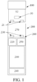
FIG. 1 is a schematic diagram of an electronic vaporization device according to an embodiment of this application; -
FIG. 2 is a schematic diagram of the vaporizer inFIG. 1 from an angle of view in an embodiment; -
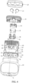
FIG. 3 is a schematic exploded diagram of each part of the vaporizer inFIG. 2 from an angle of view; -
FIG. 4 is a schematic exploded diagram of each part of the vaporizer inFIG. 2 from another angle of view; -
FIG. 5 is a schematic cross-sectional diagram of the vaporizer inFIG. 2 along a width direction; -
FIG. 6 is a schematic exploded diagram of a rigid holder and a seal element inFIG. 5 from another angle of view; -
FIG. 7 is a schematic cross-sectional diagram of the seal element inFIG. 6 opening a first air channel; -
FIG. 8 is a schematic cross-sectional diagram of a seal element sealing a first air channel according to another embodiment; and -
FIG. 9 is a schematic enlarged diagram of portion B inFIG. 8 . - For ease of understanding of this application, this application is described in further detail below with reference to the accompanying drawings and specific implementations.
- An embodiment of this application provides an electronic vaporization device. referring to
FIG. 1 , a construction of the device includes: avaporizer 100, configured to store a liquid substrate and vaporize the liquid substrate to generate an aerosol, and apower supply assembly 200, configured to supply power to thevaporizer 100. - In an optional embodiment, for example, as shown in
FIG. 1 , thepower supply assembly 200 includes: a receivingcavity 270, arranged on an end along a longitudinal direction and configured to receive and accommodate at least a part of thevaporizer 100; and a firstelectrical contact 230, at least partially exposed on a surface of the receivingcavity 270, configured to be electrically connected to thevaporizer 100 to supply power to thevaporizer 100 when at least a part of thevaporizer 100 is received and accommodated in thepower supply assembly 200. - According to the preferred embodiment shown in
FIG. 1 , a secondelectrical contact 21 is arranged on an end portion of thevaporizer 100 that is opposite to thepower supply assembly 200 along the longitudinal direction, so that when the at least a part of thevaporizer 100 is received in the receivingcavity 270, the secondelectrical contact 21 becomes conductive through being in contact with and abutting the firstelectrical contact 230. - A
seal member 260 is arranged in thepower supply assembly 200, and at least a part of an internal space of thepower supply assembly 200 is separated by theseal member 260 to form the receivingcavity 270. In the preferred embodiment shown inFIG. 1 , theseal member 260 is configured to extend along a cross section direction of thepower supply assembly 200, and is prepared by a flexible material, to prevent the liquid substrate seeping from thevaporizer 100 to the receivingcavity 270 from flowing to components such as acontroller 220 and asensor 250 inside thepower supply assembly 200. - In the preferred embodiment shown in
FIG. 1 , thepower supply assembly 200 further includes: abattery cell 210, close to another end relative to the receivingcavity 270 along the longitudinal direction for supplying power; and acontroller 220, arranged between thebattery cell 210 and an accommodating cavity, and operably guiding a current between thebattery cell 210 and the firstelectrical contact 230. - The
power supply assembly 200 includes asensor 250, configured to sense an inhalation airflow generated by thevaporizer 100 during inhalation, so that thecontroller 220 controls, based on a detection signal of thesensor 250, thebattery cell 210 to output a current to thevaporizer 100. - Further, in the preferred embodiment shown in
FIG. 1 , a charginginterface 240 is arranged on another end of thepower supply assembly 200 that is opposite to the receivingcavity 270, and is configured to charge thebattery cell 210 through a connection with an external charging device. - Further,
FIG. 2 to FIG. 5 show the structure of thevaporizer 100 inFIG. 1 according to a preferred embodiment. As shown in the figures, for a specific external construction, thevaporizer 100 includes: - a
main housing 10, roughly constructed into a hollow cylinder, and provided with an inhalation opening A located on a near end, where themain housing 10 is provided with an exposure located on a far end, making it convenient to assemble function components inside themain housing 10 through the exposure; and in use, the near end is used as an end for a user to inhale, and the far end is used as an end received in the receivingcavity 270; and - an
end cap 20, arranged on the far end, and configured to close the exposure of themain housing 10 that is close to the far end. Theend cap 20 is prepared by using a ferromagnetic material such as stainless steel, so that after being received in the receivingcavity 270, thevaporizer 100 can be magnetically attached by a magnetic attaching element arranged on thepower supply assembly 200, and thevaporizer 100 is stably received in the receivingcavity 270. - Further referring to
FIG. 2 , the secondelectrical contact 21 penetrates from outside of theend cap 20 into themain housing 10 and is at least partially exposed outside of theend cap 20, making it convenient to be conductively connected to thepower supply assembly 200. - Further, in
FIG. 2 to FIG. 5 , an inner structure of thevaporizer 100 includes: - an
aerosol output pipe 11, formed at a center of themain housing 10 and extending along the longitudinal direction, and integrally prepared with themain housing 10 by using a mold, where an upper end of theaerosol output pipe 11 is in communication with the inhalation opening A, to output the aerosol generated inside thevaporizer 100 to the inhalation opening A; and - a
liquid storage cavity 12, defined and formed by a space between theaerosol output pipe 11 and an inner wall of themain housing 10, and configured to store the liquid substrate, where - the
vaporization assembly 30 includes aliquid guide element 310 and aheating element 320, and theliquid guide element 310 is prepared by a material having capillary channels or pores, for example, a hard or porous material such as fiber cotton, a porous ceramic body, a fiberglass rope, porous ceramic, or porous glass. Theliquid guide element 310 is in fluid communication with theliquid storage cavity 12 to absorb the liquid substrate. Theliquid guide element 310 has a lower surface toward theend cap 20, and the lower surface is preferably a plane extending along a cross section of themain housing 10 and is used as a vaporization surface forming theheating element 320. Theheating element 320 heats at least a part of the liquid substrate in theliquid guide element 310 to generate the aerosol, and the aerosol is released after effusing from the vaporization surface. - In a preferred embodiment shown in
FIG. 3 , theheating element 320 is formed on the vaporization surface of theliquid guide element 310 in a manner of mounting, printing, deposition, or the like. In some embodiments, theheating element 320 may be made of a material such as stainless steel, nickel chromium alloy, iron chromium aluminum alloy, or metal titanium. As shown inFIG. 2 , theheating element 320 is a conductive trajectory in a winding or circuitous pattern. - Further, as shown in
FIG. 3 andFIG. 4 , asupport base 41 and asilicone bearing element 42 that is located in thesupport base 41 and is arranged opposite to the vaporization surface of theliquid guide element 310 are arranged between thevaporization assembly 30 and theend cap 20. During implementation, the bearingelement 42 and the vaporization surface of theliquid guide element 310 jointly define a vaporization chamber for accommodating the released aerosol. The bearingelement 42 is opposite to the vaporization surface, to receive an aerosol condensate in the vaporization chamber and a liquid substrate effusing or seeping from the vaporization surface. - Further, in the preferred embodiment shown in
FIG. 3 andFIG. 4 , to stably support and assemble thevaporization assembly 30, themain housing 10 is internally provided with: - a
silicone sleeve 50, accommodating and wrapping theliquid guide element 310; - a
rigid holder 60, configured to accommodate and support thesilicone sleeve 50 and theliquid guide element 310; and - a
seal element 80, arranged to be close to theliquid storage cavity 12, configured to seal theliquid storage cavity 21 to prevent the liquid substrate from seeping out, and at least partially wrapping therigid holder 60. - With the stable support of the
liquid guide element 310, thesilicone sleeve 50 has a firstaccommodating space 51, and theliquid guide element 310 is accommodated and supported in the firstaccommodating space 51; and therigid holder 60 has a secondaccommodating space 61, and thesilicone sleeve 50 and theliquid guide element 310 are entirely assembled in the secondaccommodating space 61. - Further referring to
FIG. 3 to FIG. 5 , to match a structure design of forming a liquid flowing channel, theseal element 80 is provided with a firstliquid guide hole 81, therigid holder 60 is provided with a secondliquid guide hole 62, and thesilicone sleeve 50 is provided with a thirdliquid guide hole 52. In use, after successively passing through the firstliquid guide hole 81, the secondliquid guide hole 62, and the thirdliquid guide hole 52, the liquid substrate in theliquid storage cavity 12 flows to theliquid guide element 310 and is absorbed, as shown by an arrow R1 inFIG. 4 andFIG. 5 , and finally is vaporized on the vaporization surface of theliquid guide element 310 and released into the vaporization chamber. - Further referring to
FIG. 3 , to match a structure of forming an inhalation airflow, the vaporization chamber defined by thesilicone bearing element 42 and theliquid guide element 310 is in communication with anair inlet hole 22 provided on theend cap 20. In addition, theseal element 80 is provided with afirst insertion hole 82 for inserting theaerosol output pipe 11. Therigid holder 60 is provided with asecond insertion hole 66 opposite to thefirst insertion hole 82 and anoutput channel 63 located on a side of a thickness direction. An airflow path during inhalation is shown by an arrow R2 inFIG. 3 . The external air enters the vaporization chamber through theair inlet hole 22 on theend cap 20, and then carries the generated aerosol to be outputted from theoutput channel 63 to theaerosol output pipe 11 connected to thesecond insertion hole 66, until it is inhaled from the inhalation opening A. - Further referring to
FIG. 4 andFIG. 6 , to supplement air to theliquid storage cavity 12 to relieve the negative pressure in theliquid storage cavity 12 as much as possible, therigid holder 60 is provided with afirst air channel 64 and asecond air channel 65. In use, thefirst air channel 64 and thesecond air channel 65 are both configured to supplement air to theliquid storage cavity 12. Thefirst air channel 64 penetrates therigid holder 60 along the longitudinal direction, and
thesecond air channel 65 is formed by a space such as a groove or an opening on an outer side wall of therigid holder 60 along a width direction. - In another optional embodiment, the
first air channel 64 and thesecond air channel 65 may not be provided simultaneously, and only one of the two channels may be implemented. - To match the foregoing structure, the
seal element 80 is provided with a blockingpart 83 configured to block and seal an air outlet end of thefirst air channel 64. As shown inFIG. 6 , the blockingpart 83 is formed by surrounding a U-shaped groove or slit 831, so that the blockingpart 83 and other parts of theseal element 80 are suspended. Usually, the blockingpart 83 blocks the air outlet end of thefirst air channel 64. However, when the increase of the negative pressure in theliquid storage cavity 12 exceeds a threshold, the blockingpart 83 can bend or warp into theliquid storage cavity 12 in response to the negative pressure change, as shown inFIG. 7 , so that the air outlet end of thefirst air channel 64 is opened, and the external air enters theliquid storage cavity 12 to relieve the negative pressure. - Further referring to an embodiment shown in
FIG. 6 , the blockingpart 83 of theseal element 80 is constructed to extend along the width direction. Certainly, in an optional embodiment, the blockingpart 83 may be at an included angle with the width direction. In a preferred embodiment, the included angle may range from -90 to 90 degrees. - Further referring to the embodiment shown in
FIG. 6 , theseal element 80 is in a shape with anend wall 810, and a side wall 820 extending from theend wall 810 and wrapping theholder 60. The blockingpart 83 is formed on theend wall 810. Theseal element 80 has anedge position 85 closest to a frontfree end 831 of the blockingpart 83. In theseal element 80 with the shape and size shown inFIG. 6 , theedge position 85 is an edge position along the width direction that is close to thefree end 831. A distance d1 between theedge position 85 and the free end is 4.2 mm. A distance d2 between a side edge of theseal element 80 and the blockingpart 83 along a thickness direction of thevaporizer 100 is 4.8 mm. A connection end 834 of the blockingpart 83 that is away from thefree end 831 is more distant from theedge position 85, so that in an assembly process, friction or deformation tension suffered by the edge position is separated by the slit defining thefree end 831 and has no impact on the connection end 834 of the blockingpart 83, thereby preventing the connection end 834 from opening thefirst air channel 64 due to deformation. - Further as shown in
FIG. 6 , the blockingpart 83 has afree end 832, and thefree end 832 is defined by the U-shaped groove or slit 831. The formedfree end 832 can deform such as bend or warp relative to theseal element 80. In addition, the U-shaped groove or slit 831 forming the blockingpart 83 extends along a width direction of theseal element 80, and the blockingpart 83 also extends along the width direction of theseal element 80. In addition, the U-shaped groove or slit 831 bends toward the center of theseal element 80. Therefore, in an assembly process, when theseal element 80 is assembled from an exposure end of themain housing 10 upward into themain housing 10, and an edge of theseal element 80 along the width direction rubs against the inner wall of themain housing 10, because the blockingpart 83 is substantially separated from the edge of theseal element 80, the blockingpart 83 does not bend or warp as the edge part rubs against the inner wall of themain housing 10, and the blockingpart 83 is maintained to substantially bond or seal a port of thefirst air channel 64 after assembly. - The
seal element 80 is provided with a throughhole 84 opposite to an air outlet end of thesecond air channel 65, so that air in thesecond air channel 65 enters theliquid storage cavity 12 through the throughhole 84. To prevent the liquid substrate in theliquid storage cavity 12 from directly massively flowing out from the throughhole 84 into thesecond air channel 65, aporous body material 70 is filled inside thesecond air channel 65 that is close to the air outlet end. During implementation, theporous body material 70 is preferably flexible, and may be made of sponge, fiber cotton, porous foam, or the like. Theporous body material 70 filled in thesecond air channel 65 can lock the seeping liquid substrate. - During implementation, in the
vaporizer 100 in a normal state, a part of the liquid substrate may be absorbed into and infiltrate theporous body material 70, and does not seep out due to the negative pressure in theliquid storage cavity 12. When the negative pressure in theliquid storage cavity 12 further increases in an inhalation process, the liquid substrate absorbed by theporous body material 70 reflows into theliquid storage cavity 12 with the external air. - In addition, in the preferred embodiment shown in
FIG. 6 , an inner diameter of the air outlet end of thesecond air channel 65 is greater than an inner diameter of thefirst air channel 64. - An inner diameter of the through
hole 84 is about 3-5 mm that is less than the inner diameter of thesecond air channel 65, thereby preventing the liquid substrate from massively seeping into thesecond air channel 65. In addition, in the preferred embodiment shown inFIG. 6 , thesecond air channel 65 is a groove that is close to an edge of a width direction of therigid holder 60, and is partially formed on the side wall of therigid holder 60. - Referring to
FIG. 6 , side walls of two sides of therigid holder 60 are provided with a recessedstructure 67 at least partially surrounding therigid holder 60 along a circumferential direction, and thesecond air channel 65 is in communication with the recessedstructure 67 to be in communication with the external air. Further, the side wall of therigid holder 60 is provided with severalcapillary grooves 68 in airflow communication with the vaporization chamber and the recessedstructure 67, so that the external air enters the recessedstructure 67 through thecapillary grooves 68. In addition, thecapillary grooves 68 can further absorb and maintain, by a capillary action, aerosol condensate generated in the vaporization chamber. - In a more preferred embodiment, air inlet ends of the
first air channel 64 and thesecond air channel 65 are directly in communication with external atmosphere through therigid holder 60 or the through hole on the wall of themain housing 10, so that pressures of the air inlet ends are the same as the atmospheric pressure, and the external air directly enters into theliquid storage cavity 12 through the air inlet ends when the negative pressure in theliquid storage cavity 12 is excessive. - Further referring to
FIG. 7 , the inner diameter of thefirst air channel 64 is changing, for example, gradually changing or gradually changing in a step-shaped manner. Preferably, the inner diameter gradually decreases along a direction close to theliquid storage cavity 12. For example, inFIG. 7 , thefirst air channel 64 includes afirst part 641, asecond part 642, and athird part 643 that are in different inner diameter sizes in sequence along the direction close to theliquid storage cavity 12, and inner diameters of thefirst part 641, thesecond part 642, and thethird part 643 gradually decrease. - As shown in
FIG. 6 , a surface of therigid holder 60 is further provided with a protrudingedge 641 surrounding the port of thefirst air channel 64, and the blockingpart 83 abuts and is bonded on the protrudingedge 641 after assembly. -
FIG. 8 and FIG. 9 are schematic structural diagrams of aseal element 80a sealing afirst air channel 60a of arigid holder 60a according to another embodiment. An inner diameter of athird part 643a of thefirst air channel 60a gradually decreases in a cone-shaped manner, and a notch is provided on an air outlet end. - A blocking
part 83 corresponding to theseal element 80a is provided with aprotrusion 832a that can extend into the notch, so that the air outlet end of thethird part 643a is sealed by theprotrusion 832a. - In addition, to further facilitate bending deformation of the blocking
part 83, a recessedstructure 833a is provided on a surface of the blockingpart 83a that is toward therigid holder 60a, which is conducive to reduce a thickness and strength of the blockingpart 83, so that the blockingpart 83 can deform such as bend or warp in response to a negative pressure change more sensitively. - It should be noted that, the specification and the accompanying drawings of this application provide preferred embodiments of this application, but is not limited to the embodiments described in this specification. Further, a person of ordinary skill in the art may make improvements or modifications according to the foregoing description, and all of the improvements and modifications should all fall within the protection scope of the attached claims of this application.
Claims (20)
- A vaporizer, configured to vaporize a liquid substrate to generate an aerosol for inhaling, comprising: a liquid storage cavity configured to store a liquid substrate; and further comprising:a vaporization assembly, in fluid communication with the liquid storage cavity, and configured to heat the liquid substrate to generate an aerosol;a seal element, at least partially sealing the liquid storage cavity;a holder, configured to support the seal element to locate the seal element between the holder and the liquid storage cavity; anda first air channel, providing a first flowing path for air to enter the liquid storage cavity, wherein the first air channel is at least partially defined by the holder, and has an air outlet end formed on a surface of the holder;the seal element comprises a blocking part configured to seal the air outlet end; and the blocking part has a free end away from a center of the seal element, and the free end is configured to bend or deform in response to a negative pressure change in the liquid storage cavity, to open the air outlet end.
- The vaporizer according to claim 1, wherein the seal element comprises a slit or groove partially surrounding the blocking part, and the blocking part is defined by the slit or the groove.
- The vaporizer according to claim 2, wherein the slit or groove is constructed to bend toward the center of the seal element.
- The vaporizer according to any one of claims 1 to 3, wherein the blocking part is constructed to extend along a cross section direction of the vaporizer.
- The vaporizer according to any one of claims 1 to 3, wherein an inner diameter of the first air channel at least partially gradually decreases along a direction close to the air outlet end.
- The vaporizer according to claim 5, wherein the inner diameter of the first air channel at least partially decreases in a step-shaped manner along the direction close to the air outlet end.
- The vaporizer according to any one of claims 1 to 3, wherein the holder is provided with a protruding edge surrounding the air outlet end of the first air channel, and the blocking part is constructed to abut the protruding edge, to seal the air outlet end.
- The vaporizer according to any one of claims 1 to 3, wherein the holder at least partially defines a second air channel, to provide a second flowing path for air to enter the liquid storage cavity, and a porous body material is arranged in the second air channel.
- The vaporizer according to claim 8, wherein the seal element is provided with a through hole opposite to the second air channel, and air in the second air channel enters the liquid storage cavity through the through hole.
- The vaporizer according to claim 9, further comprising:an air inlet, whereinan outer wall of the holder is provided with a concave cavity in airflow communication with the air inlet, and an air inlet end of the second air channel is in communication with the concave cavity.
- The vaporizer according to any one of claims 1 to 3, wherein an air pressure at an air inlet end of the first air channel is the same as an atmospheric pressure.
- A vaporizer, configured to vaporize a liquid substrate to generate an aerosol for inhaling, comprising: a liquid storage cavity configured to store a liquid substrate; and further comprising:a vaporization assembly, in fluid communication with the liquid storage cavity, and configured to heat the liquid substrate to generate an aerosol;a seal element, at least partially sealing the liquid storage cavity;a holder, configured to support the seal element to locate the seal element between the holder and the liquid storage cavity; anda first air channel, providing a first flowing path for air to enter the liquid storage cavity, wherein the first air channel is at least partially defined by the holder, and has an air outlet end formed on a surface of the holder; andthe seal element comprises an end wall and a side wall extending from the end wall and at least partially surrounding the holder, the end wall is provided with a bent slit to define and form a suspended blocking part configured to seal the air outlet end, the blocking part comprises a free end and a connection end configured to connect to other parts of the seal element, the connection end is more distant from an edge position of the end wall than the free end, and the edge position is a position in an outer edge of the end wall that is closer to the free end.
- A vaporizer, configured to vaporize a liquid substrate to generate an aerosol for inhaling, comprising: a liquid storage cavity configured to store a liquid substrate; and further comprising:a vaporization assembly, in fluid communication with the liquid storage cavity, and configured to heat the liquid substrate to generate an aerosol;a seal element, at least partially sealing the liquid storage cavity;a holder, configured to support the seal element to locate the seal element between the holder and the liquid storage cavity; andan air channel, at least partially defined by the holder, and configured to provide a flowing path for air to enter the liquid storage cavity, wherein a porous body material is arranged in the air channel.
- The vaporizer according to claim 13, wherein the seal element is provided with a through hole opposite to the air channel, and air in the air channel enters the liquid storage cavity through the through hole.
- The vaporizer according to claim 14, wherein a pore size of the through hole is less than an inner diameter of the air channel.
- The vaporizer according to any one of claims 13 to 15, wherein the porous body material is located at a position close to an air outlet end of the air channel.
- The vaporizer according to any one of claims 13 to 15, further comprising:an air inlet, whereinan outer wall of the holder is provided with a concave cavity in airflow communication with the air inlet, and an air inlet end of the air channel is in communication with the concave cavity.
- The vaporizer according to any one of claims 13 to 15, wherein an air pressure at an air inlet end of the air channel is the same as an atmospheric pressure.
- The vaporizer according to any one of claims 13 to 15, wherein the air channel comprises a hole partially extending in the holder, and a groove partially located on an outer wall of the holder.
- An electronic vaporization device, comprising a vaporizer configured to vaporize a liquid substrate to generate an aerosol, and a power supply assembly configured to supply power to the vaporizer, wherein the vaporizer comprises the vaporizer according to any one of claims 1 to 19.
Applications Claiming Priority (2)
| Application Number | Priority Date | Filing Date | Title |
|---|---|---|---|
| CN202011340644.7A CN114532594A (en) | 2020-11-25 | 2020-11-25 | Atomizer and electronic atomization device |
| PCT/CN2021/131272 WO2022111358A1 (en) | 2020-11-25 | 2021-11-17 | Atomiser and electronic atomising apparatus |
Publications (2)
| Publication Number | Publication Date |
|---|---|
| EP4252562A1 true EP4252562A1 (en) | 2023-10-04 |
| EP4252562A4 EP4252562A4 (en) | 2024-05-15 |
Family
ID=81660171
Family Applications (1)
| Application Number | Title | Priority Date | Filing Date |
|---|---|---|---|
| EP21896859.2A Pending EP4252562A4 (en) | 2020-11-25 | 2021-11-17 | ATOMIZER AND ELECTRONIC ATOMIZATION DEVICE |
Country Status (4)
| Country | Link |
|---|---|
| US (1) | US20230413915A1 (en) |
| EP (1) | EP4252562A4 (en) |
| CN (1) | CN114532594A (en) |
| WO (1) | WO2022111358A1 (en) |
Families Citing this family (4)
| Publication number | Priority date | Publication date | Assignee | Title |
|---|---|---|---|---|
| CN218474054U (en) * | 2022-08-10 | 2023-02-14 | 深圳市合元科技有限公司 | Electronic atomization device |
| CN116210984B (en) * | 2023-03-30 | 2025-11-28 | 立讯精密工业股份有限公司 | Atomizing device |
| CN220756584U (en) * | 2023-08-07 | 2024-04-12 | 深圳麦克韦尔科技有限公司 | Atomizer and atomizing device |
| EP4529783A1 (en) * | 2023-09-29 | 2025-04-02 | JT International SA | Aerosol generating systems and cartridges for use in aerosol generating systems |
Family Cites Families (14)
| Publication number | Priority date | Publication date | Assignee | Title |
|---|---|---|---|---|
| DE19633472A1 (en) * | 1996-08-20 | 1997-03-20 | Dieter Meyer | Appts.. for removing gas or air e.g. from drinks container |
| KR101387801B1 (en) * | 2013-09-12 | 2014-04-21 | 박선순 | Electronic cigarette with the pressure chamber type |
| WO2017059571A1 (en) * | 2015-10-08 | 2017-04-13 | Fontem Holdings 1 B.V. | Liquid supply for an electronic smoking device |
| CN206808661U (en) * | 2016-06-22 | 2017-12-29 | 深圳市合元科技有限公司 | Oil storage cup and atomizer for atomizer |
| CN207040889U (en) * | 2017-04-19 | 2018-02-27 | 深圳市合元科技有限公司 | Electronic cigarette equilibrium air pressure atomizer |
| CN109279172A (en) * | 2018-09-14 | 2019-01-29 | 膳魔师(中国)家庭制品有限公司 | An exhaust valve structure of a sealed container |
| CN209498584U (en) * | 2018-12-26 | 2019-10-18 | 深圳市合元科技有限公司 | Vape atomizer and electronic cigarette |
| CN210611013U (en) * | 2019-06-28 | 2020-05-26 | 深圳市合元科技有限公司 | Electronic cigarette atomizer and electronic cigarette |
| CN110338465B (en) * | 2019-07-16 | 2024-10-15 | 深圳麦克韦尔科技有限公司 | Scavenging valve and electronic atomizing device |
| CN111165878A (en) * | 2019-11-19 | 2020-05-19 | 深圳雾芯科技有限公司 | an atomizing device |
| CN111011933B (en) * | 2019-12-26 | 2025-02-18 | 深圳麦克韦尔科技有限公司 | Electronic atomization device and atomizer thereof |
| CN111657548A (en) * | 2020-05-15 | 2020-09-15 | 深圳麦克韦尔科技有限公司 | Electronic atomization device and atomizer thereof |
| CN111631437B (en) * | 2020-05-29 | 2025-08-29 | 深圳麦克韦尔科技有限公司 | Atomizers and electronic atomization devices |
| CN214431782U (en) * | 2020-11-25 | 2021-10-22 | 深圳市合元科技有限公司 | Atomizer and electronic atomization device |
-
2020
- 2020-11-25 CN CN202011340644.7A patent/CN114532594A/en active Pending
-
2021
- 2021-11-17 EP EP21896859.2A patent/EP4252562A4/en active Pending
- 2021-11-17 US US18/038,707 patent/US20230413915A1/en active Pending
- 2021-11-17 WO PCT/CN2021/131272 patent/WO2022111358A1/en not_active Ceased
Also Published As
| Publication number | Publication date |
|---|---|
| CN114532594A (en) | 2022-05-27 |
| EP4252562A4 (en) | 2024-05-15 |
| US20230413915A1 (en) | 2023-12-28 |
| WO2022111358A1 (en) | 2022-06-02 |
Similar Documents
| Publication | Publication Date | Title |
|---|---|---|
| US20230413915A1 (en) | Vaporizer and electronic vaporization device | |
| US20230389615A1 (en) | Vaporizer and electronic vaporization device | |
| US12543791B2 (en) | Cartridges for vaporizer devices | |
| US11944122B2 (en) | Vapor provision device with liquid capture | |
| CN213587425U (en) | Electronic Cigarettes and Electronic Cigarettes | |
| CN214431782U (en) | Atomizer and electronic atomization device | |
| US20250098773A1 (en) | Vaporizer and electronic vaporization device | |
| CN215347044U (en) | Atomizer and electronic atomization device | |
| EP4169395A1 (en) | Aerosol generating device and aerosol electronic inhaler | |
| EP4289295A1 (en) | Atomizer and electronic atomization device | |
| JP7351490B2 (en) | Porous elements for steam supply systems | |
| EP4248768A1 (en) | Aerosol generating apparatus | |
| US20240041125A1 (en) | Vaporizer and electronic vaporization device | |
| CN114847527A (en) | Atomizer and electronic atomization device | |
| CN115670013A (en) | An atomizer and its electronic atomization device | |
| EP4192275B1 (en) | A cartridge for a vapour generating system | |
| CN215684857U (en) | Atomizer and electronic atomization device | |
| CN218354596U (en) | Electronic atomization device and atomizer | |
| EP4248779A1 (en) | Vaporizer and electronic vaporization device | |
| CN220274915U (en) | Atomizers and electronic atomization devices | |
| CN218737218U (en) | Atomizer and electronic atomization device thereof | |
| EP4282289A1 (en) | Atomiser and electronic atomising apparatus | |
| EP4487704A1 (en) | Atomizer and electronic atomization device | |
| CN224192928U (en) | Electronic atomizing device | |
| CN216416018U (en) | Atomizer and electronic atomization device |
Legal Events
| Date | Code | Title | Description |
|---|---|---|---|
| STAA | Information on the status of an ep patent application or granted ep patent |
Free format text: STATUS: THE INTERNATIONAL PUBLICATION HAS BEEN MADE |
|
| PUAI | Public reference made under article 153(3) epc to a published international application that has entered the european phase |
Free format text: ORIGINAL CODE: 0009012 |
|
| STAA | Information on the status of an ep patent application or granted ep patent |
Free format text: STATUS: REQUEST FOR EXAMINATION WAS MADE |
|
| 17P | Request for examination filed |
Effective date: 20230531 |
|
| AK | Designated contracting states |
Kind code of ref document: A1 Designated state(s): AL AT BE BG CH CY CZ DE DK EE ES FI FR GB GR HR HU IE IS IT LI LT LU LV MC MK MT NL NO PL PT RO RS SE SI SK SM TR |
|
| DAV | Request for validation of the european patent (deleted) | ||
| DAX | Request for extension of the european patent (deleted) | ||
| STAA | Information on the status of an ep patent application or granted ep patent |
Free format text: STATUS: EXAMINATION IS IN PROGRESS |
|
| A4 | Supplementary search report drawn up and despatched |
Effective date: 20240417 |
|
| RIC1 | Information provided on ipc code assigned before grant |
Ipc: A24F 40/42 20200101ALI20240411BHEP Ipc: A24F 40/485 20200101ALI20240411BHEP Ipc: A24F 40/10 20200101AFI20240411BHEP |
|
| 17Q | First examination report despatched |
Effective date: 20240429 |