EP4252526A1 - Container for at least one gardening tool and related gardening kit - Google Patents
Container for at least one gardening tool and related gardening kit Download PDFInfo
- Publication number
- EP4252526A1 EP4252526A1 EP23162379.4A EP23162379A EP4252526A1 EP 4252526 A1 EP4252526 A1 EP 4252526A1 EP 23162379 A EP23162379 A EP 23162379A EP 4252526 A1 EP4252526 A1 EP 4252526A1
- Authority
- EP
- European Patent Office
- Prior art keywords
- container
- box
- gardening
- shaped body
- tool
- Prior art date
- Legal status (The legal status is an assumption and is not a legal conclusion. Google has not performed a legal analysis and makes no representation as to the accuracy of the status listed.)
- Granted
Links
Images




Classifications
-
- A—HUMAN NECESSITIES
- A01—AGRICULTURE; FORESTRY; ANIMAL HUSBANDRY; HUNTING; TRAPPING; FISHING
- A01G—HORTICULTURE; CULTIVATION OF VEGETABLES, FLOWERS, RICE, FRUIT, VINES, HOPS OR SEAWEED; FORESTRY; WATERING
- A01G25/00—Watering gardens, fields, sports grounds or the like
-
- B—PERFORMING OPERATIONS; TRANSPORTING
- B25—HAND TOOLS; PORTABLE POWER-DRIVEN TOOLS; MANIPULATORS
- B25H—WORKSHOP EQUIPMENT, e.g. FOR MARKING-OUT WORK; STORAGE MEANS FOR WORKSHOPS
- B25H3/00—Storage means or arrangements for workshops facilitating access to, or handling of, work tools or instruments
- B25H3/006—Storage means specially adapted for one specific hand apparatus, e.g. an electric drill
-
- B—PERFORMING OPERATIONS; TRANSPORTING
- B25—HAND TOOLS; PORTABLE POWER-DRIVEN TOOLS; MANIPULATORS
- B25H—WORKSHOP EQUIPMENT, e.g. FOR MARKING-OUT WORK; STORAGE MEANS FOR WORKSHOPS
- B25H3/00—Storage means or arrangements for workshops facilitating access to, or handling of, work tools or instruments
- B25H3/02—Boxes
-
- B—PERFORMING OPERATIONS; TRANSPORTING
- B65—CONVEYING; PACKING; STORING; HANDLING THIN OR FILAMENTARY MATERIAL
- B65H—HANDLING THIN OR FILAMENTARY MATERIAL, e.g. SHEETS, WEBS, CABLES
- B65H75/00—Storing webs, tapes, or filamentary material, e.g. on reels
- B65H75/02—Cores, formers, supports, or holders for coiled, wound, or folded material, e.g. reels, spindles, bobbins, cop tubes, cans, mandrels or chucks
- B65H75/34—Cores, formers, supports, or holders for coiled, wound, or folded material, e.g. reels, spindles, bobbins, cop tubes, cans, mandrels or chucks specially adapted or mounted for storing and repeatedly paying-out and re-storing lengths of material provided for particular purposes, e.g. anchored hoses, power cables
- B65H75/36—Cores, formers, supports, or holders for coiled, wound, or folded material, e.g. reels, spindles, bobbins, cop tubes, cans, mandrels or chucks specially adapted or mounted for storing and repeatedly paying-out and re-storing lengths of material provided for particular purposes, e.g. anchored hoses, power cables without essentially involving the use of a core or former internal to a stored package of material, e.g. with stored material housed within casing or container, or intermittently engaging a plurality of supports as in sinuous or serpentine fashion
- B65H75/362—Cores, formers, supports, or holders for coiled, wound, or folded material, e.g. reels, spindles, bobbins, cop tubes, cans, mandrels or chucks specially adapted or mounted for storing and repeatedly paying-out and re-storing lengths of material provided for particular purposes, e.g. anchored hoses, power cables without essentially involving the use of a core or former internal to a stored package of material, e.g. with stored material housed within casing or container, or intermittently engaging a plurality of supports as in sinuous or serpentine fashion with stored material housed within a casing or container
-
- A—HUMAN NECESSITIES
- A01—AGRICULTURE; FORESTRY; ANIMAL HUSBANDRY; HUNTING; TRAPPING; FISHING
- A01G—HORTICULTURE; CULTIVATION OF VEGETABLES, FLOWERS, RICE, FRUIT, VINES, HOPS OR SEAWEED; FORESTRY; WATERING
- A01G25/00—Watering gardens, fields, sports grounds or the like
- A01G25/14—Hand watering devices, e.g. watering cans
-
- B—PERFORMING OPERATIONS; TRANSPORTING
- B65—CONVEYING; PACKING; STORING; HANDLING THIN OR FILAMENTARY MATERIAL
- B65H—HANDLING THIN OR FILAMENTARY MATERIAL, e.g. SHEETS, WEBS, CABLES
- B65H2701/00—Handled material; Storage means
- B65H2701/30—Handled filamentary material
- B65H2701/33—Hollow or hose-like material
Definitions
- the present invention relates to a container for at least one gardening tool and a related gardening kit.
- the container and gardening kit find application in the field of hobby and DIY equipment for the maintenance of green areas.
- these packagings In addition to fulfilling the function of keeping the tools side by side for better display, these packagings must have a minimum rigidity to ensure the protection of the tools from any impact and at the same time ensure a transportability of the kit.
- the technical task at the basis of the present invention is to propose a container for at least one gardening tool and related gardening kit which overcome the aforementioned drawbacks of the prior art.
- a further object of the present invention is to provide a gardening kit which can minimise the use of raw materials for the production of the packaging as much as possible, eliminating all the parts of the packaging in plastic.
- a further object of the present invention is to provide a container for at least one gardening tool and related kit so that they can have a high flexibility of use and which are particularly attractive and functional when sold on the shelves of the large-scale retailer.
- the technical task set and the objects specified are substantially attained by a container defining a compartment for containing at least one or more gardening tools having a shelf body adapted to favour a removable connection between one or more tools and the container itself. Furthermore, the technical task set and the objects specified are substantially attained by a container provided with at least one window to facilitate the operations of moving the container and with attachment means to favour the suspended positioning of the container by resting it on a supporting element such as a tap.
- the container allows the packaging costs to be reduced since the same container houses all the components constituting the irrigation kit.
- the number 1 overall indicates a container for at least one gardening tool 102 and the number 100 indicates a gardening kit comprising the aforementioned container 1.
- gardening tool 102 it is meant, by way of non-limiting example, a tool which can be used to dispense water, such as an irrigation gun, a sprinkler or a spray nozzle, or a fitting, i.e., an element for connecting the aforementioned tools together.
- a tool which can be used to dispense water such as an irrigation gun, a sprinkler or a spray nozzle, or a fitting, i.e., an element for connecting the aforementioned tools together.
- gardening tool 102 means manual tools used for the care of green areas, such as shovels, rakes, or other.
- irrigation guns dispensing attachments, spray nozzles and fittings, these, which can be joined in the category of gardening tools 102, have a discharge groove, defined precisely by a cylindrical portion G, which allows a quick attachment with other tools.
- Irrigation hoses can also fall into the category of gardening tools, but due to the fact that they can be connected and/or contained in the container, they will simply be referred to as watering or irrigation hoses 101.
- irrigation hoses 101 also have a cylindrical outer surface, similarly defining the aforementioned cylindrical portion G. Functions and couplings of gardening tools 102, and irrigation hoses 101 will be better described hereinafter.
- the container 1 comprises a box-shaped body 2 defining a compartment V therein to allow the housing of at least one tool 102 inside the aforesaid compartment V or to allow the extraction of at least one tool 102 from the inside of said compartment V.
- the box-shaped body 2 has a substantially flat bottom 3 at the base.
- the bottom 3 preferably has a quadrangular contour with rounded edges. Without departing from the scope of protection of the present invention, the bottom 3 can have a polygonal contour or an arched contour.
- Said bottom 3 delimits the compartment V of the container 1 below.
- At least one perimetral wall 4 preferably having a closed contour in transverse section, extends away from the bottom 3. That is, the closed contour of the transverse section of the at least one perimetral wall 4 has a contour substantially similar to that of the bottom 3.
- said at least one wall 4 peripherally surrounds the bottom 3 so as to laterally delimit the compartment V of the container 1.
- the bottom 3 can be peripherally surrounded by a plurality of side walls 4, parallel to each other and facing in pairs of two, as long as the plurality of side walls 4 define a closed contour in transverse section.
- the compartment V of the container 1 is laterally delimited by the at least one wall 4, below the bottom 3 and open above. From the open side of the container 2, a user can insert or extract tools into/from the container 1.
- first and a second side 21,22 opposite each other and defined respectively by a right side and a left side of the container 1, and a third and a fourth side 23, 24, opposite each other and defined respectively by the front side and rear side of the container 1.
- first side 21 continues, along the extension of the perimetral wall 4, at opposite ends, with third and fourth sides 23,24 and the latter converge from opposite sides towards the second side 22.
- Said box-shaped body 2 preferably at a first side 21, has at least one shelf 5 connected to the perimetral wall 4 and extending away therefrom towards the outside of the box-shaped body 2.
- Said at least one shelf 5 is preferably connected to the perimetral wall 4 at a portion thereof which is farther away with respect to the wall of the bottom 3.
- said at least one shelf 5 is connected at the open side of the compartment V.
- Said shelf 5 is made in a single piece with the perimetral wall 4. That is, the shelf 5 is made with the same material with which the perimetral wall 4 is made.
- the box-shaped body 2 has a shelf 5 at the first side 21, while in figure 1C the box-shaped body has a shelf 5 at the first side 21 and a second shelf 5 at the second side 22.
- the container 1 can have a plurality of shelves 5 arranged on the periphery of the perimetral wall 4, each extending away from the perimetral wall 4.
- the box-shaped body 2 can comprise one or more shelves 5 located on the same side or on parallel or contiguous sides of the box-shaped body 2 itself.
- Each shelf 5 has an angled extension with respect to the perimetral wall 4. More precisely, each shelf 5 is angled with respect to the perimetral wall 4 with an obtuse angle, preferably a substantially right angle.
- Each shelf 5 has a proximal region 51, jointed and connected to the perimetral wall 4 and a distal region 52 which is cantilevered with respect to the perimetral wall 4 as, for example, illustrated in figure 7 .
- At least one recess 6 is provided at the aforesaid shelf 5.
- the at least one shelf 5 can include a plurality of recesses 6.
- Said recess 6 defines a seat for the reversible coupling of at least one gardening tool 102 to the box-shaped body 2 so as to allow a temporary placement during the non-use of the tool itself.
- Each recess 6 comprises a bottom portion 61, preferably arched, located near the proximal region 51 of the shelf 5.
- the bottom portion 61 continues in its extension, with a pair of intermediate sections 62, facing each other, ending at the distal region 52.
- the pair of intermediate sections 62 opens at the distal region 52 defining therein a free space 60 open and accessible from the distal region 52. Looking at the recess 6 from above, it can be noted how this has a U-shaped contour with the connected part defined by the bottom portion 61 and with the part with the parallel sections defined by the pair of intermediate sections 62. The free space 60 open and accessible from the distal region of the shelf 52 is within this U-shaped contour.
- the user In the step of coupling a tool on the recess 6, the user must push the tool 102, and in particular the cylindrical portion G, until the resistance opposed by the means of restraint 63 is overcome. Once the resistance opposed by the means of restraint 63 has been overcome, the tool 102 enters the free space until it abuttingly reaches the bottom portion 61. Any movement of the container 1 does not affect the tool 102 - recess 6 coupling due to the resistance opposed by the means of restraint 63 which retain the tool 102 in the recess 6.
- the user In the step of uncoupling a tool 102 from the recess 6, the user must pull the tool 102 until again overcoming the resistance opposed by the means of restraint 63. Once the resistance opposed by the means of restraint 63 has been overcome, the tool 102 can be picked up in order to be used.
- the coupling of the tool 102 in the recess 6 occurs by placing the tool with a section above the shelf 5 and the remaining section below the same.
- the means of restraint 63 are defined by a pair of teeth 64.
- Each tooth, belonging to the pair of teeth 64 is positioned on the end part of a corresponding intermediate section, belonging to the pair of intermediate sections 62, being positioned close to the distal region 52 of the shelf 5.
- Each tooth, belonging to the pair of teeth 64 is facing the reciprocal tooth and extends from a respective intermediate section towards the other intermediate section. Said pair of teeth 64 subtends a first distance d which is less than a second distance D subtended between the pair of intermediate sections 62.
- the coupling between tool 102 and recess 6 is of the interference type between pair of teeth 64 and tool 6, during the insertion and extraction of the tool 102 from the recess 6, while it has clearance between pair of intermediate sections 62 and tool 102 when the latter is entirely inserted inside the free space 60.
- the pair of intermediate sections 62 belonging to each 6 can subtend distances D, D' which are different from each other. This is to allow the possibility of coupling a wider range of tools 102 of various sizes having different diameters of the cylindrical portion G to the container 1.
- Said pair of teeth 64 is elastically deformable, reversibly, from a close position, during which the pair of teeth 64 provides a resistance to the insertion of the cylindrical portion G of the tool 102 against the pair of teeth 64 or at the output of the cylindrical portion G of the tool 102 when the same is previously inserted inside the recess 6, at a distanced position, during which the pair of teeth 64 allows the passage of the cylindrical portion G of the tool 102 inside the recess 6.
- At least one window 7 at the perimetral wall 4, passing through and forming a communication between compartment V and outside the box-shaped body 2.
- Said at least one window 7 defines a gripping handle for the box-shaped body 2 adapted to favour displacements or transport thereof.
- the window 7 can be obtained on a side, for example the second side 22, opposite the side on which the shelf 5 is applied, for example the first side 21.
- the window 7 can be obtained on a side, for example the third side 23, adjacent to the side on which the shelf 5 is applied, for example the first side 21.
- the window 7 can be obtained on a side, for example the third side 23, interposed between a pair of sides, first and second 21,22, on which a pair of shelves 5 is distributed. It remains understood that, without departing from the scope of protection of the present invention, the window 7 is placed on a side of the box-shaped body not engaged by the shelf 5 so as to allow a correct gripping thereof without the opening of the window being partially occluded by a tool 102 coupled to the shelf 5.
- the container 1 includes attachment means 8.
- Said attachment means 8 comprise a support 81, having a slot 82, engageable by an element adapted to favour the suspended positioning of the box-shaped body 2, connected below to a sliding element 83 slidably coupled to the perimetral wall 4.
- Said sliding element 83 favours a controlled translation reversible from an extended position, in which the support 81 protrudes inside the compartment V, to a shortened position in which the support 81 is at least partially, preferably fully, contained inside the compartment V.
- the movement of the sliding element 83 to reach the elongated position occurs due to a distancing thereof from the container 1 according to a direction indicated in figure 4A with A while the movement of the sliding element 83 to reach the shortened position occurs due to an approach thereof to the container according to a direction indicated with figure 4B with B.
- Said sliding element 83 comprises a pair of extensions 84 sliding inside a guide 41 obtained on the peripheral wall 4 on the part thereof facing the inside of the compartment V.
- Said pair of extensions 81 better depicted in figure 3A, 3A', 3B, 3B' , ends, opposite to the part connected to the slot 82, with stop means 85 adapted to enter against the guide 41 upon reaching the elongated position.
- the guide 41 is defined by a flange inside which the pair of extensions 81 can slide. It remains understood that without departing from the scope of protection of the present invention, the guide 41 can be defined by another system, such as a pair of eyelets which allow the sliding of the extensions 84.
- Said slot 82 has a main opening 82a surmounted by a top opening 82b, said top opening being engageable with a support element such as a dispensing spout of a tap T.
- a further object of the present invention is a gardening kit 100 comprising an irrigation hose 101 of the flexible or self-extending type, at least one gardening tool 102, ending at one end with a connecting section having at least one cylindrical portion G, and a container 1 for receiving the irrigation hose and at least said gardening tool 102.
- gardening tool 102 a tool is meant which is capable of assisting in normal garden activities, including preferably, but not exclusively, the distribution of water and the care of green areas.
- gardening tool 102 it is meant, by way of non-limiting example, a tool which can be used to dispense water, such as an irrigation gun, a sprinkler or a spray nozzle, or a fitting, i.e., an element for connecting the aforementioned tools together or further an irrigation hose 101.
- a tool which can be used to dispense water such as an irrigation gun, a sprinkler or a spray nozzle, or a fitting, i.e., an element for connecting the aforementioned tools together or further an irrigation hose 101.
- gardening tool 102 means manual tools used for the care of green areas, such as shovels, rakes, or other.
- the irrigation hose 101 when the irrigation hose 101 is not used, it can be stored in a rolled-up configuration inside the compartment V and said at least one gardening tool 102, when not used, can be coupled to a corresponding recess 6, made on the shelf 5, to keep the gardening tool 102 connected and visible with respect to the box-shaped body 2.
- the coupling of the gardening tool 102 inside the recess 6 and the decoupling of the gardening tool 102 from the recess 6 occurs respectively as a result of a thrust force I or a traction force O applied by an operator on the gardening tool 102.
- the irrigation hose 101 can be wound on itself and inserted inside the container 1.
- the present invention achieves the proposed objects by making a container 1 for at least one gardening tool 102, preferably for several gardening tools, which allows to keep the at least one gardening tool 102 in order and visible.
- the present invention allows to collect an irrigation hose 101 and gardening tools 102 inside the compartment V of the container 1 and/or in connection with the container 1 in a single place, allowing the user to have a single containment space of the equipment for the maintenance of green areas.
- At least one window 7 on the perimetral wall 4 allows to easily transport and/or move the container 1 to any place of shelter or maintenance of the green area.
- attachment means 8 then allows the possibility of connecting the container 1 in a suspended position on support structures, such as a tap, without therefore needing to install shelves or other equipment for supporting the container 1.
- the fact that the aforesaid attachment means 8 are retractable in a shortened position then allows, if there is no need to place the container in a suspended position, to store the attachment means 8 inside the compartment V without taking up useful space which can be occupied by the gardening tools 102 or the irrigation hose 101.
- the present invention allows the visible containment of the gardening tools 120, allowing the user to immediately see the tools available.
- the gardening kit 100 allows to provide an assembly for displaying a set of gardening tools, minimising the material for creating the packaging.
- the gardening kit 100 in addition to being attractive during display on the shelves of the large-scale retailer, is particularly attractive to the buyer for the fact of buying together the gardening tools and the necessary container, which can be useful for other functions such as the containment of soil, or small clippings during pruning operations.
Landscapes
- Engineering & Computer Science (AREA)
- Mechanical Engineering (AREA)
- Water Supply & Treatment (AREA)
- Life Sciences & Earth Sciences (AREA)
- Environmental Sciences (AREA)
- Details Of Rigid Or Semi-Rigid Containers (AREA)
- Cultivation Receptacles Or Flower-Pots, Or Pots For Seedlings (AREA)
Abstract
Description
- The present invention relates to a container for at least one gardening tool and a related gardening kit.
- The container and gardening kit find application in the field of hobby and DIY equipment for the maintenance of green areas.
- Several tools exist in the state of the art for the care and maintenance of green areas. There are tools such as devices for dispensing water, watering hoses, fittings and/or attachments for the connection, for example, of watering guns to watering hoses.
- All these tools, sold individually or in groups, do not have their own place to be stored when not in use. That is, once the use of these devices has ended, the user places them in the most varied places such as in a toolbox, which very often also contains mechanical tools and hardware, or possibly in a corner of the garden so that they are easily available. In the first case, since the spaces of the box are occupied by both gardening tools and mechanic tools and hardware, it is not always easy to find the tools because they are hidden by the others. In the second case, there is a tendency to prefer an open space which however has the disadvantage of being exposed to atmospheric agents which cause a discolouration of the tools up to the real damage thereof.
- Moreover, when these devices must be used in a specific area of the garden, the user is forced to go back and forth between the area of the garden on which he is intervening and the area where the tools are stored to pick up the most suitable tool for the activity he is carrying out.
- The disadvantages of the prior art are also present in the step of presenting a kit of gardening tools for sale. In fact, with the exception of cases in which the buyer wants a single and specific tool, the promotion of gardening kits has packagings which are expensive, generates waste and are not particularly attractive for sale.
- Gardening kits, which often comprise at least one watering gun (or possibly even two guns), a dispensing nozzle (possibly replacing the second gun) and a fitting are generally contained in transparent plastic packagings.
- In addition to fulfilling the function of keeping the tools side by side for better display, these packagings must have a minimum rigidity to ensure the protection of the tools from any impact and at the same time ensure a transportability of the kit.
- This entails, for a company which produces gardening tools, the obligation to make packagings which affect the final cost of the product to the large-scale retailer and therefore to the final buyer.
- Once the product has been purchased, the user opens the packaging, picks up the tools and throws away the packaging. Therefore, the packaging is not perceived by the consumer as a valuable element but only as an element to be lost, and as such, an element which does not in any way affect the final consumer on the purchase of the gardening kit. If the increasingly stringent environmental regulations on the production of plastic waste are then considered, it is immediately understood how the traditional packagings are an element to be avoided or reduced as much as possible. In this context, the technical task at the basis of the present invention is to propose a container for at least one gardening tool and related gardening kit which overcome the aforementioned drawbacks of the prior art.
- In particular, it is an object of the present invention to provide a container for at least one gardening tool which can be useful for storing the gardening tools after their use and which is easily transportable.
- A further object of the present invention is to provide a gardening kit which can minimise the use of raw materials for the production of the packaging as much as possible, eliminating all the parts of the packaging in plastic. A further object of the present invention is to provide a container for at least one gardening tool and related kit so that they can have a high flexibility of use and which are particularly attractive and functional when sold on the shelves of the large-scale retailer.
- The technical task set and the objects specified are substantially attained by a container defining a compartment for containing at least one or more gardening tools having a shelf body adapted to favour a removable connection between one or more tools and the container itself. Furthermore, the technical task set and the objects specified are substantially attained by a container provided with at least one window to facilitate the operations of moving the container and with attachment means to favour the suspended positioning of the container by resting it on a supporting element such as a tap.
- Advantageously, the container allows the packaging costs to be reduced since the same container houses all the components constituting the irrigation kit.
- Further features and advantages of the present invention will become more apparent from the indicative and thus non-limiting description of an embodiment of a container for at least one gardening tool and related gardening kit comprising the technical features set out in one or more of the appended claims.
- The dependent claims correspond to possible embodiments of the invention.
- Such a description will be set out below with reference to the appended drawings, which are provided solely for illustrative and therefore non-limiting purposes, in which:
-
figure 1A is an axonometric view of a container for at least one tool in accordance with a first possible embodiment of the present invention; -
figure 1B is an axonometric view of a container for at least one tool in accordance with a second possible embodiment of the present invention; -
figure 1C is an axonometric view of a container for at least one tool in accordance with a third possible embodiment of the present invention; -
figure 2 is a plan view of the container offigure 1A ; -
figure 3A is a sectional view, according to the plane III-III offigure 2 , illustrating the container in a first mode of use in which the container can be placed in a suspended position; -
figure 3A' is an enlarged view offigure 3A illustrating a construction detail of the container; -
figure 3B is a sectional view, according to the plane III-III offigure 2 illustrating the container in a second mode of use in which the container can be supported on a support surface; -
figure 3B' is an enlarged view offigure 3B illustrating a construction detail of the container; -
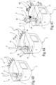
figure 4A illustrates in axonometric view the container of the first mode of use illustrated infigure 3A ; -
figure 4B illustrates in axonometric view the container in the second mode of use illustrated infigure 4B ; -
figure 4C shows an example of application of thecontainer 1 in the second mode of use; -
figure 5 illustrates in axonometric view a gardening kit comprising the container offigures 1A-4B and a gardening tool depicted in a decoupled configuration; -
figure 6 illustrates in axonometric view the kit offigure 5 in a configuration in which gardening tool and container are in the coupled configuration; -
figure 7 illustrates in enlarged axonometric view a construction detail and coupling between container and gardening tool illustrated infigure 6 . -
figure 8 illustrates in axonometric view the gardening kit containing an irrigation hose. - With reference to the cited figures, the
number 1 overall indicates a container for at least onegardening tool 102 and thenumber 100 indicates a gardening kit comprising theaforementioned container 1. - By
gardening tool 102 it is meant, by way of non-limiting example, a tool which can be used to dispense water, such as an irrigation gun, a sprinkler or a spray nozzle, or a fitting, i.e., an element for connecting the aforementioned tools together. - Further,
gardening tool 102 means manual tools used for the care of green areas, such as shovels, rakes, or other. - Almost all of the gardening tools mentioned have a connecting section provided with at least one cylindrical portion G.
- Referring, for example, to irrigation guns, dispensing attachments, spray nozzles and fittings, these, which can be joined in the category of
gardening tools 102, have a discharge groove, defined precisely by a cylindrical portion G, which allows a quick attachment with other tools. - Irrigation hoses can also fall into the category of gardening tools, but due to the fact that they can be connected and/or contained in the container, they will simply be referred to as watering or
irrigation hoses 101. - The fact remains that the
irrigation hoses 101 also have a cylindrical outer surface, similarly defining the aforementioned cylindrical portion G. Functions and couplings ofgardening tools 102, andirrigation hoses 101 will be better described hereinafter. - The
container 1 comprises a box-shaped body 2 defining a compartment V therein to allow the housing of at least onetool 102 inside the aforesaid compartment V or to allow the extraction of at least onetool 102 from the inside of said compartment V. - The box-
shaped body 2 has a substantiallyflat bottom 3 at the base. As can be seen from the accompanying figures, thebottom 3 preferably has a quadrangular contour with rounded edges. Without departing from the scope of protection of the present invention, thebottom 3 can have a polygonal contour or an arched contour. - Said
bottom 3 delimits the compartment V of thecontainer 1 below. - At least one
perimetral wall 4, preferably having a closed contour in transverse section, extends away from thebottom 3. That is, the closed contour of the transverse section of the at least oneperimetral wall 4 has a contour substantially similar to that of thebottom 3. - As visible from the accompanying figures, said at least one
wall 4 peripherally surrounds thebottom 3 so as to laterally delimit the compartment V of thecontainer 1. Without departing from the scope of protection of the present invention, thebottom 3 can be peripherally surrounded by a plurality ofside walls 4, parallel to each other and facing in pairs of two, as long as the plurality ofside walls 4 define a closed contour in transverse section. - Therefore, the compartment V of the
container 1 is laterally delimited by the at least onewall 4, below thebottom 3 and open above. From the open side of thecontainer 2, a user can insert or extract tools into/from thecontainer 1. - Due to the box shape of the
container 1, it is possible to identify a first and asecond side container 1, and a third and afourth side container 1. As can be seen from the accompanying figures, thefirst side 21 continues, along the extension of theperimetral wall 4, at opposite ends, with third andfourth sides second side 22. - Said box-
shaped body 2, preferably at afirst side 21, has at least oneshelf 5 connected to theperimetral wall 4 and extending away therefrom towards the outside of the box-shaped body 2. - Said at least one
shelf 5 is preferably connected to theperimetral wall 4 at a portion thereof which is farther away with respect to the wall of thebottom 3. - That is, said at least one
shelf 5 is connected at the open side of the compartment V. -
Said shelf 5 is made in a single piece with theperimetral wall 4. That is, theshelf 5 is made with the same material with which theperimetral wall 4 is made. - As can be seen in
figures 1A, 1B , the box-shapedbody 2 has ashelf 5 at thefirst side 21, while infigure 1C the box-shaped body has ashelf 5 at thefirst side 21 and asecond shelf 5 at thesecond side 22. - Without departing from the scope of protection of the present invention, the
container 1 can have a plurality ofshelves 5 arranged on the periphery of theperimetral wall 4, each extending away from theperimetral wall 4. Further, the box-shapedbody 2 can comprise one ormore shelves 5 located on the same side or on parallel or contiguous sides of the box-shapedbody 2 itself. - Each
shelf 5 has an angled extension with respect to theperimetral wall 4. More precisely, eachshelf 5 is angled with respect to theperimetral wall 4 with an obtuse angle, preferably a substantially right angle. - Each
shelf 5 has aproximal region 51, jointed and connected to theperimetral wall 4 and adistal region 52 which is cantilevered with respect to theperimetral wall 4 as, for example, illustrated infigure 7 . - At least one
recess 6 is provided at theaforesaid shelf 5. As can be seen in the accompanying figures, the at least oneshelf 5 can include a plurality ofrecesses 6. -
Said recess 6 defines a seat for the reversible coupling of at least onegardening tool 102 to the box-shapedbody 2 so as to allow a temporary placement during the non-use of the tool itself. - Each
recess 6 comprises abottom portion 61, preferably arched, located near theproximal region 51 of theshelf 5. - The
bottom portion 61 continues in its extension, with a pair ofintermediate sections 62, facing each other, ending at thedistal region 52. - The pair of
intermediate sections 62 opens at thedistal region 52 defining therein afree space 60 open and accessible from thedistal region 52. Looking at therecess 6 from above, it can be noted how this has a U-shaped contour with the connected part defined by thebottom portion 61 and with the part with the parallel sections defined by the pair ofintermediate sections 62. Thefree space 60 open and accessible from the distal region of theshelf 52 is within this U-shaped contour. - On the pair of
intermediate sections 62, opposite to the part connected to thebottom portion 61, there are means of restraint 63 adapted to favour a reversible coupling of at least onetool 102 to the box-shapedbody 2. - In the step of coupling a tool on the
recess 6, the user must push thetool 102, and in particular the cylindrical portion G, until the resistance opposed by the means of restraint 63 is overcome. Once the resistance opposed by the means of restraint 63 has been overcome, thetool 102 enters the free space until it abuttingly reaches thebottom portion 61. Any movement of thecontainer 1 does not affect the tool 102 -recess 6 coupling due to the resistance opposed by the means of restraint 63 which retain thetool 102 in therecess 6. - In the step of uncoupling a
tool 102 from therecess 6, the user must pull thetool 102 until again overcoming the resistance opposed by the means of restraint 63. Once the resistance opposed by the means of restraint 63 has been overcome, thetool 102 can be picked up in order to be used. - As can be seen in
figures 6 and 7 , the coupling of thetool 102 in therecess 6 occurs by placing the tool with a section above theshelf 5 and the remaining section below the same. - In the preferred embodiment, the means of restraint 63 are defined by a pair of
teeth 64. Each tooth, belonging to the pair ofteeth 64, is positioned on the end part of a corresponding intermediate section, belonging to the pair ofintermediate sections 62, being positioned close to thedistal region 52 of theshelf 5. Each tooth, belonging to the pair ofteeth 64, is facing the reciprocal tooth and extends from a respective intermediate section towards the other intermediate section. Said pair ofteeth 64 subtends a first distance d which is less than a second distance D subtended between the pair ofintermediate sections 62. - As a result of this difference in distances subtended respectively between pair of
teeth 64 and pair ofintermediate sections 62, the coupling betweentool 102 andrecess 6 is of the interference type between pair ofteeth 64 andtool 6, during the insertion and extraction of thetool 102 from therecess 6, while it has clearance between pair ofintermediate sections 62 andtool 102 when the latter is entirely inserted inside thefree space 60. - As can be seen in the accompanying figures, the pair of
intermediate sections 62 belonging to each 6 can subtend distances D, D' which are different from each other. This is to allow the possibility of coupling a wider range oftools 102 of various sizes having different diameters of the cylindrical portion G to thecontainer 1. - Said pair of
teeth 64 is elastically deformable, reversibly, from a close position, during which the pair ofteeth 64 provides a resistance to the insertion of the cylindrical portion G of thetool 102 against the pair ofteeth 64 or at the output of the cylindrical portion G of thetool 102 when the same is previously inserted inside therecess 6, at a distanced position, during which the pair ofteeth 64 allows the passage of the cylindrical portion G of thetool 102 inside therecess 6. - There is at least one
window 7 at theperimetral wall 4, passing through and forming a communication between compartment V and outside the box-shapedbody 2. Said at least onewindow 7 defines a gripping handle for the box-shapedbody 2 adapted to favour displacements or transport thereof. As can be seen for example infigure 1A , thewindow 7 can be obtained on a side, for example thesecond side 22, opposite the side on which theshelf 5 is applied, for example thefirst side 21. - As can be seen for example in
figure 1B , thewindow 7 can be obtained on a side, for example thethird side 23, adjacent to the side on which theshelf 5 is applied, for example thefirst side 21. - Further, as can be seen for example in
figure 1C , thewindow 7 can be obtained on a side, for example thethird side 23, interposed between a pair of sides, first and second 21,22, on which a pair ofshelves 5 is distributed. It remains understood that, without departing from the scope of protection of the present invention, thewindow 7 is placed on a side of the box-shaped body not engaged by theshelf 5 so as to allow a correct gripping thereof without the opening of the window being partially occluded by atool 102 coupled to theshelf 5. - To obtain a suspended positioning of the
container 1, i.e., in a position where thebottom 3 is not abutted on a support surface, thecontainer 1 includes attachment means 8. - Said attachment means 8 comprise a
support 81, having aslot 82, engageable by an element adapted to favour the suspended positioning of the box-shapedbody 2, connected below to a slidingelement 83 slidably coupled to theperimetral wall 4. - Said sliding
element 83 favours a controlled translation reversible from an extended position, in which thesupport 81 protrudes inside the compartment V, to a shortened position in which thesupport 81 is at least partially, preferably fully, contained inside the compartment V. - The movement of the sliding
element 83 to reach the elongated position occurs due to a distancing thereof from thecontainer 1 according to a direction indicated infigure 4A with A while the movement of the slidingelement 83 to reach the shortened position occurs due to an approach thereof to the container according to a direction indicated withfigure 4B with B. - Said sliding
element 83 comprises a pair ofextensions 84 sliding inside aguide 41 obtained on theperipheral wall 4 on the part thereof facing the inside of the compartment V. - Said pair of
extensions 81, better depicted infigure 3A, 3A', 3B, 3B' , ends, opposite to the part connected to theslot 82, with stop means 85 adapted to enter against theguide 41 upon reaching the elongated position. - As can be seen in
figures 3A-3B and4C , theguide 41 is defined by a flange inside which the pair ofextensions 81 can slide. It remains understood that without departing from the scope of protection of the present invention, theguide 41 can be defined by another system, such as a pair of eyelets which allow the sliding of theextensions 84. - Said
slot 82 has amain opening 82a surmounted by a top opening 82b, said top opening being engageable with a support element such as a dispensing spout of a tap T. - A further object of the present invention is a
gardening kit 100 comprising anirrigation hose 101 of the flexible or self-extending type, at least onegardening tool 102, ending at one end with a connecting section having at least one cylindrical portion G, and acontainer 1 for receiving the irrigation hose and at least saidgardening tool 102. - By
gardening tool 102, a tool is meant which is capable of assisting in normal garden activities, including preferably, but not exclusively, the distribution of water and the care of green areas. - To cite some examples, by gardening
tool 102 it is meant, by way of non-limiting example, a tool which can be used to dispense water, such as an irrigation gun, a sprinkler or a spray nozzle, or a fitting, i.e., an element for connecting the aforementioned tools together or further anirrigation hose 101. - Further,
gardening tool 102 means manual tools used for the care of green areas, such as shovels, rakes, or other. - In a first configuration of use of the
kit 100, when theirrigation hose 101 is not used, it can be stored in a rolled-up configuration inside the compartment V and said at least onegardening tool 102, when not used, can be coupled to acorresponding recess 6, made on theshelf 5, to keep thegardening tool 102 connected and visible with respect to the box-shapedbody 2. - The coupling of the
gardening tool 102 inside therecess 6 and the decoupling of thegardening tool 102 from therecess 6 occurs respectively as a result of a thrust force I or a traction force O applied by an operator on thegardening tool 102. - By applying the thrust force I on the
gardening tool 102, when this is placed in contact with therecess 6, an elastic deformation of the pair ofteeth 64 is promoted which causes a temporary distancing of the pair ofteeth 64 to allow the entry of the cylindrical portion G inside thefree space 60, thus allowing the coupling of thegardening tool 102 inside therecess 6. - By applying the traction force O, when the
gardening tool 102 is already coupled to therecess 6, an elastic deformation of the pair ofteeth 64 is again promoted which causes a temporary distancing of the pair ofteeth 64 adapted to allow the release of the cylindrical portion G from the inside of thefree space 60 thus allowing the decoupling of thegardening tool 102 from inside therecess 6. - In a second configuration of use, actuated as a result of the different dimensions of the
recesses 6, and in particular of the distances D, D' subtended between the pair ofintermediate sections 62, it is possible to insert or extract, in the same manner described above, an end section of theirrigation hose 101, coupling the cylindrical portion G of theirrigation hose 101 inside therecess 6 of suitable dimensions to accommodate it. This is actuated to immediately make available and visible a termination of theirrigation hose 101 which should be connected to a supply source. - In a third configuration of use, illustrated in
figure 8 , theirrigation hose 101 can be wound on itself and inserted inside thecontainer 1. - The present invention achieves the proposed objects by making a
container 1 for at least onegardening tool 102, preferably for several gardening tools, which allows to keep the at least onegardening tool 102 in order and visible. Advantageously, the present invention allows to collect anirrigation hose 101 andgardening tools 102 inside the compartment V of thecontainer 1 and/or in connection with thecontainer 1 in a single place, allowing the user to have a single containment space of the equipment for the maintenance of green areas. - The provision of at least one
window 7 on theperimetral wall 4 allows to easily transport and/or move thecontainer 1 to any place of shelter or maintenance of the green area. - The provision of the attachment means 8 then allows the possibility of connecting the
container 1 in a suspended position on support structures, such as a tap, without therefore needing to install shelves or other equipment for supporting thecontainer 1. The fact that the aforesaid attachment means 8 are retractable in a shortened position then allows, if there is no need to place the container in a suspended position, to store the attachment means 8 inside the compartment V without taking up useful space which can be occupied by thegardening tools 102 or theirrigation hose 101. - With particular reference then to the connection between the
container 1 and thegardening tool 102, and in particular the connection between the latter and theshelf 5, the present invention allows the visible containment of the gardening tools 120, allowing the user to immediately see the tools available. - Advantageously, the
gardening kit 100 allows to provide an assembly for displaying a set of gardening tools, minimising the material for creating the packaging. - Advantageously, the
gardening kit 100, in addition to being attractive during display on the shelves of the large-scale retailer, is particularly attractive to the buyer for the fact of buying together the gardening tools and the necessary container, which can be useful for other functions such as the containment of soil, or small clippings during pruning operations.
Claims (16)
- A container (1), for at least one gardening tool (102), comprising:- a box-shaped body (2) having a bottom (3) and at least one perimetral wall (4), said perimetral wall (4) being connected to the bottom (3) and extending away from the bottom (3); said perimetral wall (4) defining a compartment (V) therein for the containment of at least one gardening tool (102), delimited below by the bottom (3) and open above;characterised in that said box-shaped body (2) has, on a first side (21), at least one shelf (5), connected to the perimetral wall (4) and extending away therefrom towards the outside of the box-shaped body (2), comprising at least one recess (6) defining a seat for the reversible coupling of at least one gardening tool (102) to the box-shaped body (2) to allow a temporary placement of the accessory during the non-use thereof.
- The container (1) according to claim 1, characterised in that said shelf (5), preferably made in a single piece with the perimetral wall (4), comprises a proximal region (51), jointed and connected to the perimetral wall (4), and a distal region (52), cantilevered with respect to the perimetral wall (4).
- The container (1) according to claim 2, characterised in that the said recess (6) comprises:- a bottom portion (61), preferably arched, located near the proximal region (51);- a pair of intermediate sections (62), facing each other, extending from the bottom portion (61) up to the distal region (52); said pair of intermediate sections (62) defining a free space (60) therein which is open and accessible from the distal region (52);- means of restraint (63) adapted to favour a reversible coupling of at least one gardening tool (102) to the box-shaped body (2) placing the accessory with a portion above the shelf (5) and with a portion below the shelf (5).
- The container (1) according to claim 3, characterised in that said means of restraint (63) are defined by a pair of teeth (64), each tooth (64) being connected to a respective intermediate section (62), elastically reversibly deformable, as a result of the insertion of a cylindrical portion (G) of the gardening tool (102) placed against the pair of teeth (64), from a close position, during which the pair of teeth (64) provides a resistance to the insertion of the cylindrical portion (G) of the tool or at the output of the cylindrical portion (G) of the tool when the latter is coupled inside the recess (6), in a spaced position, during which the pair of teeth (64) allows the passage of the cylindrical portion (G) of the gardening tool (102) inside the recess (6).
- The container (1) according to claim 4, characterised in that said pair of teeth (64) subtends a first distance (d) therebetween and said pair of intermediate sections (62), subtends therebetween a second distance (D); said second distance (D) being greater than the first distance (d).
- The container (1) according to any one of the preceding claims, characterised in that the said shelf (5) comprises a plurality of recesses (6).
- The container (1) according to any one of the preceding claims, characterised in that the said box-shaped body (2) comprises one or more shelves (5) located on a first side (21) or distributed on the sides of the box-shaped body (2) adjacent or parallel to each other.
- The container (1) according to any one of the preceding claims, characterised in that it also comprises at least one window (7), obtained from the perimetral wall (4) and passing through it to define an access area between the inside and the outside of the box-shaped body (2), adapted to define a gripping means of the box-shaped body (2) for transporting or moving it.
- The container (1) according to claims 1 and 8, wherein at least one window (7) is located on a second side (22) of the box-shaped body (2); said second side (22) being opposite the first side (21) on which the shelf (5) is applied.
- The container (1) according to claim 1, characterised in that it also comprises at least one window (7), obtained on the perimetral wall (4) and passing through it to define an access area between the inside and the outside of the box-shaped body (2), adapted to define a gripping means on the box-shaped body (2) for transporting or moving it; said at least one window (7) being located on a third side (23) of the box-shaped body (2); said third side (23) being adjacent to the first side (21) on which the shelf (5) is applied.
- The container (1) according to any one of the preceding claims, characterised in that it also comprises means of attachment (8) comprising:- a support (81) having a through-slot (82) engageable by an element passing through the slot to promote a suspended position of the box-shaped body (2) to the element; said suspended position being implemented with the bottom (3) lacking a support on an abutment surface;- a sliding element (83), slidably coupled to the perimetral wall (4), from an extended position, in which the support (81) protrudes inside the compartment (V), to a contracted position, in which the support (81) is at least partially, preferably fully, contained inside the compartment (V).
- The container (1) according to claim 11, wherein said slot (82) has a main opening (82a) surmounted by a top opening (82b); said top opening (82b) being engageable in support on a spout of a tap (T).
- A gardening kit (100) of the type comprising:- a container (1) according to any one of claims 1 to 12;- at least one gardening tool (102) terminating at one end with a coupling fitting having at least one cylindrical portion (G); characterised in that said at least one gardening tool (102), when not in use, is coupled to said at least one recess (6) in order to maintain said at least one gardening tool (102) connected to the box-shaped body (2).
- The gardening kit (100) according to claim 13, characterised in that said at least one gardening tool (102) being couplable and decouplable from the respective recess (6) as a result of a corresponding thrust force (I) or traction force (O) applied by an operator on the gardening tool (102); said thrust force (I) promoting an elastic deformation on the pair of teeth (64) adapted to allow a temporary distancing of the pair of teeth (64) to allow the entrance of the cylindrical portion (G) inside the free space (60) and the subsequent coupling of the gardening tool (102) inside the recess (6); said traction force (O) promoting an elastic deformation on the pair of teeth (64) adapted to allow a temporary distancing of the pair of teeth (64) in order to allow the output of the cylindrical portion (G) from the outside of the free space (60) and the subsequent decoupling of the gardening tool (102) outside the recess (6).
- The gardening kit (100) according to claim 13, characterised in that it also comprises a flexible irrigation hose (101), stored at least partially, when not in use, in a rolled-up configuration in the compartment (V) defined inside the box-shaped body (2).
- The gardening kit (100) according to claim 15, characterised in that said irrigation hose (101) can have a cylindrical portion (G) at one end which can be coupled inside a recess (6) so as to make the aforesaid end usable to facilitate the retrieval and subsequent connection thereof to a source of supply liquids.
Applications Claiming Priority (1)
| Application Number | Priority Date | Filing Date | Title |
|---|---|---|---|
| IT102022000006032A IT202200006032A1 (en) | 2022-03-28 | 2022-03-28 | Container for at least one gardening accessory and related gardening kit |
Publications (3)
| Publication Number | Publication Date |
|---|---|
| EP4252526A1 true EP4252526A1 (en) | 2023-10-04 |
| EP4252526C0 EP4252526C0 (en) | 2024-07-31 |
| EP4252526B1 EP4252526B1 (en) | 2024-07-31 |
Family
ID=82100477
Family Applications (1)
| Application Number | Title | Priority Date | Filing Date |
|---|---|---|---|
| EP23162379.4A Active EP4252526B1 (en) | 2022-03-28 | 2023-03-16 | Container for at least one gardening tool and related gardening kit |
Country Status (4)
| Country | Link |
|---|---|
| EP (1) | EP4252526B1 (en) |
| ES (1) | ES2988313T3 (en) |
| IT (1) | IT202200006032A1 (en) |
| PL (1) | PL4252526T3 (en) |
Citations (5)
| Publication number | Priority date | Publication date | Assignee | Title |
|---|---|---|---|---|
| FR2845631A1 (en) * | 2002-10-15 | 2004-04-16 | Serge Arrecgros | Holder for garden tools has container with opening and clips for tools around its periphery |
| WO2005095065A1 (en) * | 2004-04-01 | 2005-10-13 | Keter Plastic Ltd. | Rack for holding tools and other implements |
| US20070200309A1 (en) * | 2006-11-30 | 2007-08-30 | James Coppedge | Implement and material management system |
| US20110290827A1 (en) * | 2010-05-25 | 2011-12-01 | Briggs & Stratton Corporation | Garden hose booster system |
| WO2013084239A1 (en) * | 2011-12-06 | 2013-06-13 | Keter Plastic Ltd. | Tool caddy |
-
2022
- 2022-03-28 IT IT102022000006032A patent/IT202200006032A1/en unknown
-
2023
- 2023-03-16 PL PL23162379.4T patent/PL4252526T3/en unknown
- 2023-03-16 EP EP23162379.4A patent/EP4252526B1/en active Active
- 2023-03-16 ES ES23162379T patent/ES2988313T3/en active Active
Patent Citations (5)
| Publication number | Priority date | Publication date | Assignee | Title |
|---|---|---|---|---|
| FR2845631A1 (en) * | 2002-10-15 | 2004-04-16 | Serge Arrecgros | Holder for garden tools has container with opening and clips for tools around its periphery |
| WO2005095065A1 (en) * | 2004-04-01 | 2005-10-13 | Keter Plastic Ltd. | Rack for holding tools and other implements |
| US20070200309A1 (en) * | 2006-11-30 | 2007-08-30 | James Coppedge | Implement and material management system |
| US20110290827A1 (en) * | 2010-05-25 | 2011-12-01 | Briggs & Stratton Corporation | Garden hose booster system |
| WO2013084239A1 (en) * | 2011-12-06 | 2013-06-13 | Keter Plastic Ltd. | Tool caddy |
Also Published As
| Publication number | Publication date |
|---|---|
| PL4252526T3 (en) | 2024-10-21 |
| IT202200006032A1 (en) | 2023-09-28 |
| ES2988313T3 (en) | 2024-11-20 |
| EP4252526C0 (en) | 2024-07-31 |
| EP4252526B1 (en) | 2024-07-31 |
Similar Documents
| Publication | Publication Date | Title |
|---|---|---|
| US7063275B2 (en) | Sprayer having a spray shield and a spray shield retainer | |
| US20140331504A1 (en) | Attachment guide comb conduit | |
| USD989915S1 (en) | Nozzle for garden hose | |
| USD1043002S1 (en) | Pet vacuum cleaner | |
| US6629383B2 (en) | Landscape edging system with stakes attached | |
| EP4252526B1 (en) | Container for at least one gardening tool and related gardening kit | |
| US20150267847A1 (en) | Tool Cabinet Having Integral Air Lines | |
| US11267602B2 (en) | Refuse bag insertion device and method | |
| USD1078801S1 (en) | Garage for robotic lawn mower | |
| US20060230562A1 (en) | Implements With Handles and Working Ends and Method of Use Thereof | |
| US11944991B2 (en) | Dispensing assemblies and related methods | |
| AU2018204579B2 (en) | Dispensing assemblies and related methods | |
| US20160367049A1 (en) | Extendable display hanger | |
| US6481182B1 (en) | Plastic gloves assemblage for point-of-sales display and storage | |
| US20200016621A1 (en) | Garden sprinkler securing structure | |
| USD918349S1 (en) | Vacuum hose tubing adapter | |
| EP0976319B1 (en) | Sheath for secateurs | |
| USD887721S1 (en) | Paint brush with angled handle and without a ferrule | |
| USD505313S1 (en) | Hose reel | |
| US20070124996A1 (en) | Plant flat handle | |
| WO2006056788A1 (en) | Stackable watering can | |
| US10238257B2 (en) | Vacuum attachment including a pressurized air source | |
| EP4203662A1 (en) | Tool storage device | |
| US20190373822A1 (en) | Collapsible Mulch Dispenser | |
| EP1174052A1 (en) | Flexible hose-carrying handle |
Legal Events
| Date | Code | Title | Description |
|---|---|---|---|
| PUAI | Public reference made under article 153(3) epc to a published international application that has entered the european phase |
Free format text: ORIGINAL CODE: 0009012 |
|
| STAA | Information on the status of an ep patent application or granted ep patent |
Free format text: STATUS: THE APPLICATION HAS BEEN PUBLISHED |
|
| AK | Designated contracting states |
Kind code of ref document: A1 Designated state(s): AL AT BE BG CH CY CZ DE DK EE ES FI FR GB GR HR HU IE IS IT LI LT LU LV MC ME MK MT NL NO PL PT RO RS SE SI SK SM TR |
|
| STAA | Information on the status of an ep patent application or granted ep patent |
Free format text: STATUS: REQUEST FOR EXAMINATION WAS MADE |
|
| 17P | Request for examination filed |
Effective date: 20231228 |
|
| RBV | Designated contracting states (corrected) |
Designated state(s): AL AT BE BG CH CY CZ DE DK EE ES FI FR GB GR HR HU IE IS IT LI LT LU LV MC ME MK MT NL NO PL PT RO RS SE SI SK SM TR |
|
| GRAP | Despatch of communication of intention to grant a patent |
Free format text: ORIGINAL CODE: EPIDOSNIGR1 |
|
| STAA | Information on the status of an ep patent application or granted ep patent |
Free format text: STATUS: GRANT OF PATENT IS INTENDED |
|
| RIC1 | Information provided on ipc code assigned before grant |
Ipc: B25H 3/02 20060101ALI20240402BHEP Ipc: B65H 75/36 20060101ALI20240402BHEP Ipc: B25H 3/00 20060101ALI20240402BHEP Ipc: A01G 25/00 20060101AFI20240402BHEP |
|
| INTG | Intention to grant announced |
Effective date: 20240422 |
|
| GRAS | Grant fee paid |
Free format text: ORIGINAL CODE: EPIDOSNIGR3 |
|
| GRAA | (expected) grant |
Free format text: ORIGINAL CODE: 0009210 |
|
| STAA | Information on the status of an ep patent application or granted ep patent |
Free format text: STATUS: THE PATENT HAS BEEN GRANTED |
|
| AK | Designated contracting states |
Kind code of ref document: B1 Designated state(s): AL AT BE BG CH CY CZ DE DK EE ES FI FR GB GR HR HU IE IS IT LI LT LU LV MC ME MK MT NL NO PL PT RO RS SE SI SK SM TR |
|
| REG | Reference to a national code |
Ref country code: CH Ref legal event code: EP Ref country code: GB Ref legal event code: FG4D |
|
| REG | Reference to a national code |
Ref country code: DE Ref legal event code: R096 Ref document number: 602023000303 Country of ref document: DE |
|
| REG | Reference to a national code |
Ref country code: IE Ref legal event code: FG4D |
|
| U01 | Request for unitary effect filed |
Effective date: 20240805 |
|
| U07 | Unitary effect registered |
Designated state(s): AT BE BG DE DK EE FI FR IT LT LU LV MT NL PT SE SI Effective date: 20240820 |
|
| REG | Reference to a national code |
Ref country code: ES Ref legal event code: FG2A Ref document number: 2988313 Country of ref document: ES Kind code of ref document: T3 Effective date: 20241120 |
|
| PG25 | Lapsed in a contracting state [announced via postgrant information from national office to epo] |
Ref country code: NO Free format text: LAPSE BECAUSE OF FAILURE TO SUBMIT A TRANSLATION OF THE DESCRIPTION OR TO PAY THE FEE WITHIN THE PRESCRIBED TIME-LIMIT Effective date: 20241031 |
|
| PG25 | Lapsed in a contracting state [announced via postgrant information from national office to epo] |
Ref country code: GR Free format text: LAPSE BECAUSE OF FAILURE TO SUBMIT A TRANSLATION OF THE DESCRIPTION OR TO PAY THE FEE WITHIN THE PRESCRIBED TIME-LIMIT Effective date: 20241101 |
|
| PG25 | Lapsed in a contracting state [announced via postgrant information from national office to epo] |
Ref country code: IS Free format text: LAPSE BECAUSE OF FAILURE TO SUBMIT A TRANSLATION OF THE DESCRIPTION OR TO PAY THE FEE WITHIN THE PRESCRIBED TIME-LIMIT Effective date: 20241130 |
|
| PG25 | Lapsed in a contracting state [announced via postgrant information from national office to epo] |
Ref country code: HR Free format text: LAPSE BECAUSE OF FAILURE TO SUBMIT A TRANSLATION OF THE DESCRIPTION OR TO PAY THE FEE WITHIN THE PRESCRIBED TIME-LIMIT Effective date: 20240731 |
|
| PG25 | Lapsed in a contracting state [announced via postgrant information from national office to epo] |
Ref country code: RS Free format text: LAPSE BECAUSE OF FAILURE TO SUBMIT A TRANSLATION OF THE DESCRIPTION OR TO PAY THE FEE WITHIN THE PRESCRIBED TIME-LIMIT Effective date: 20241031 |
|
| PG25 | Lapsed in a contracting state [announced via postgrant information from national office to epo] |
Ref country code: RS Free format text: LAPSE BECAUSE OF FAILURE TO SUBMIT A TRANSLATION OF THE DESCRIPTION OR TO PAY THE FEE WITHIN THE PRESCRIBED TIME-LIMIT Effective date: 20241031 Ref country code: NO Free format text: LAPSE BECAUSE OF FAILURE TO SUBMIT A TRANSLATION OF THE DESCRIPTION OR TO PAY THE FEE WITHIN THE PRESCRIBED TIME-LIMIT Effective date: 20241031 Ref country code: IS Free format text: LAPSE BECAUSE OF FAILURE TO SUBMIT A TRANSLATION OF THE DESCRIPTION OR TO PAY THE FEE WITHIN THE PRESCRIBED TIME-LIMIT Effective date: 20241130 Ref country code: HR Free format text: LAPSE BECAUSE OF FAILURE TO SUBMIT A TRANSLATION OF THE DESCRIPTION OR TO PAY THE FEE WITHIN THE PRESCRIBED TIME-LIMIT Effective date: 20240731 Ref country code: GR Free format text: LAPSE BECAUSE OF FAILURE TO SUBMIT A TRANSLATION OF THE DESCRIPTION OR TO PAY THE FEE WITHIN THE PRESCRIBED TIME-LIMIT Effective date: 20241101 |
|
| U20 | Renewal fee for the european patent with unitary effect paid |
Year of fee payment: 3 Effective date: 20250225 |
|
| PG25 | Lapsed in a contracting state [announced via postgrant information from national office to epo] |
Ref country code: SM Free format text: LAPSE BECAUSE OF FAILURE TO SUBMIT A TRANSLATION OF THE DESCRIPTION OR TO PAY THE FEE WITHIN THE PRESCRIBED TIME-LIMIT Effective date: 20240731 |
|
| PG25 | Lapsed in a contracting state [announced via postgrant information from national office to epo] |
Ref country code: CZ Free format text: LAPSE BECAUSE OF FAILURE TO SUBMIT A TRANSLATION OF THE DESCRIPTION OR TO PAY THE FEE WITHIN THE PRESCRIBED TIME-LIMIT Effective date: 20240731 |
|
| PG25 | Lapsed in a contracting state [announced via postgrant information from national office to epo] |
Ref country code: SK Free format text: LAPSE BECAUSE OF FAILURE TO SUBMIT A TRANSLATION OF THE DESCRIPTION OR TO PAY THE FEE WITHIN THE PRESCRIBED TIME-LIMIT Effective date: 20240731 |
|
| PLBE | No opposition filed within time limit |
Free format text: ORIGINAL CODE: 0009261 |
|
| STAA | Information on the status of an ep patent application or granted ep patent |
Free format text: STATUS: NO OPPOSITION FILED WITHIN TIME LIMIT |
|
| 26N | No opposition filed |
Effective date: 20250501 |
|
| PG25 | Lapsed in a contracting state [announced via postgrant information from national office to epo] |
Ref country code: MC Free format text: LAPSE BECAUSE OF FAILURE TO SUBMIT A TRANSLATION OF THE DESCRIPTION OR TO PAY THE FEE WITHIN THE PRESCRIBED TIME-LIMIT Effective date: 20240731 |
|
| PG25 | Lapsed in a contracting state [announced via postgrant information from national office to epo] |
Ref country code: IE Free format text: LAPSE BECAUSE OF NON-PAYMENT OF DUE FEES Effective date: 20250316 |
|
| REG | Reference to a national code |
Ref country code: CH Ref legal event code: U11 Free format text: ST27 STATUS EVENT CODE: U-0-0-U10-U11 (AS PROVIDED BY THE NATIONAL OFFICE) Effective date: 20260401 |
|
| U20 | Renewal fee for the european patent with unitary effect paid |
Year of fee payment: 4 Effective date: 20260226 |
|
| PG25 | Lapsed in a contracting state [announced via postgrant information from national office to epo] |
Ref country code: RO Free format text: LAPSE BECAUSE OF FAILURE TO SUBMIT A TRANSLATION OF THE DESCRIPTION OR TO PAY THE FEE WITHIN THE PRESCRIBED TIME-LIMIT Effective date: 20240731 |
|
| PGFP | Annual fee paid to national office [announced via postgrant information from national office to epo] |
Ref country code: PL Payment date: 20260223 Year of fee payment: 4 |
|
| PG25 | Lapsed in a contracting state [announced via postgrant information from national office to epo] |
Ref country code: CY Free format text: LAPSE BECAUSE OF FAILURE TO SUBMIT A TRANSLATION OF THE DESCRIPTION OR TO PAY THE FEE WITHIN THE PRESCRIBED TIME-LIMIT Effective date: 20240731 |
|
| PG25 | Lapsed in a contracting state [announced via postgrant information from national office to epo] |
Ref country code: TR Free format text: LAPSE BECAUSE OF FAILURE TO SUBMIT A TRANSLATION OF THE DESCRIPTION OR TO PAY THE FEE WITHIN THE PRESCRIBED TIME-LIMIT Effective date: 20240731 |
|
| PGFP | Annual fee paid to national office [announced via postgrant information from national office to epo] |
Ref country code: ES Payment date: 20260410 Year of fee payment: 4 |
|
| PGFP | Annual fee paid to national office [announced via postgrant information from national office to epo] |
Ref country code: CH Payment date: 20260401 Year of fee payment: 4 |