EP4252097B1 - Device, system and method for throttling current to peripherals - Google Patents
Device, system and method for throttling current to peripherals Download PDFInfo
- Publication number
- EP4252097B1 EP4252097B1 EP21847560.6A EP21847560A EP4252097B1 EP 4252097 B1 EP4252097 B1 EP 4252097B1 EP 21847560 A EP21847560 A EP 21847560A EP 4252097 B1 EP4252097 B1 EP 4252097B1
- Authority
- EP
- European Patent Office
- Prior art keywords
- current
- peripherals
- given
- throttling
- circuit
- Prior art date
- Legal status (The legal status is an assumption and is not a legal conclusion. Google has not performed a legal analysis and makes no representation as to the accuracy of the status listed.)
- Active
Links
Images


Classifications
-
- H—ELECTRICITY
- H02—GENERATION; CONVERSION OR DISTRIBUTION OF ELECTRIC POWER
- H02H—EMERGENCY PROTECTIVE CIRCUIT ARRANGEMENTS
- H02H9/00—Emergency protective circuit arrangements for limiting excess current or voltage without disconnection
- H02H9/02—Emergency protective circuit arrangements for limiting excess current or voltage without disconnection responsive to excess current
-
- G—PHYSICS
- G06—COMPUTING OR CALCULATING; COUNTING
- G06F—ELECTRIC DIGITAL DATA PROCESSING
- G06F1/00—Details not covered by groups G06F3/00 - G06F13/00 and G06F21/00
- G06F1/26—Power supply means, e.g. regulation thereof
-
- G—PHYSICS
- G06—COMPUTING OR CALCULATING; COUNTING
- G06F—ELECTRIC DIGITAL DATA PROCESSING
- G06F1/00—Details not covered by groups G06F3/00 - G06F13/00 and G06F21/00
- G06F1/16—Constructional details or arrangements
- G06F1/18—Packaging or power distribution
- G06F1/189—Power distribution
-
- G—PHYSICS
- G06—COMPUTING OR CALCULATING; COUNTING
- G06F—ELECTRIC DIGITAL DATA PROCESSING
- G06F1/00—Details not covered by groups G06F3/00 - G06F13/00 and G06F21/00
- G06F1/26—Power supply means, e.g. regulation thereof
- G06F1/28—Supervision thereof, e.g. detecting power-supply failure by out of limits supervision
-
- G—PHYSICS
- G06—COMPUTING OR CALCULATING; COUNTING
- G06F—ELECTRIC DIGITAL DATA PROCESSING
- G06F1/00—Details not covered by groups G06F3/00 - G06F13/00 and G06F21/00
- G06F1/26—Power supply means, e.g. regulation thereof
- G06F1/30—Means for acting in the event of power-supply failure or interruption, e.g. power-supply fluctuations
- G06F1/305—Means for acting in the event of power-supply failure or interruption, e.g. power-supply fluctuations in the event of power-supply fluctuations
-
- G—PHYSICS
- G06—COMPUTING OR CALCULATING; COUNTING
- G06F—ELECTRIC DIGITAL DATA PROCESSING
- G06F1/00—Details not covered by groups G06F3/00 - G06F13/00 and G06F21/00
- G06F1/26—Power supply means, e.g. regulation thereof
- G06F1/32—Means for saving power
- G06F1/3203—Power management, i.e. event-based initiation of a power-saving mode
- G06F1/3234—Power saving characterised by the action undertaken
- G06F1/3287—Power saving characterised by the action undertaken by switching off individual functional units in the computer system
-
- H—ELECTRICITY
- H02—GENERATION; CONVERSION OR DISTRIBUTION OF ELECTRIC POWER
- H02H—EMERGENCY PROTECTIVE CIRCUIT ARRANGEMENTS
- H02H1/00—Details of emergency protective circuit arrangements
- H02H1/0007—Details of emergency protective circuit arrangements concerning the detecting means
-
- H—ELECTRICITY
- H04—ELECTRIC COMMUNICATION TECHNIQUE
- H04B—TRANSMISSION
- H04B1/00—Details of transmission systems, not covered by a single one of groups H04B3/00 - H04B13/00; Details of transmission systems not characterised by the medium used for transmission
- H04B1/38—Transceivers, i.e. devices in which transmitter and receiver form a structural unit and in which at least one part is used for functions of transmitting and receiving
- H04B1/3827—Portable transceivers
- H04B1/3833—Hand-held transceivers
-
- H—ELECTRICITY
- H04—ELECTRIC COMMUNICATION TECHNIQUE
- H04B—TRANSMISSION
- H04B1/00—Details of transmission systems, not covered by a single one of groups H04B3/00 - H04B13/00; Details of transmission systems not characterised by the medium used for transmission
- H04B1/38—Transceivers, i.e. devices in which transmitter and receiver form a structural unit and in which at least one part is used for functions of transmitting and receiving
- H04B1/40—Circuits
-
- H—ELECTRICITY
- H04—ELECTRIC COMMUNICATION TECHNIQUE
- H04W—WIRELESS COMMUNICATION NETWORKS
- H04W52/00—Power management, e.g. Transmission Power Control [TPC] or power classes
- H04W52/02—Power saving arrangements
- H04W52/0209—Power saving arrangements in terminal devices
- H04W52/0261—Power saving arrangements in terminal devices managing power supply demand, e.g. depending on battery level
- H04W52/0274—Power saving arrangements in terminal devices managing power supply demand, e.g. depending on battery level by switching on or off the equipment or parts thereof
- H04W52/0277—Power saving arrangements in terminal devices managing power supply demand, e.g. depending on battery level by switching on or off the equipment or parts thereof according to available power supply, e.g. switching off when a low battery condition is detected
-
- H—ELECTRICITY
- H04—ELECTRIC COMMUNICATION TECHNIQUE
- H04W—WIRELESS COMMUNICATION NETWORKS
- H04W52/00—Power management, e.g. Transmission Power Control [TPC] or power classes
- H04W52/02—Power saving arrangements
- H04W52/0209—Power saving arrangements in terminal devices
- H04W52/0261—Power saving arrangements in terminal devices managing power supply demand, e.g. depending on battery level
- H04W52/0274—Power saving arrangements in terminal devices managing power supply demand, e.g. depending on battery level by switching on or off the equipment or parts thereof
- H04W52/028—Power saving arrangements in terminal devices managing power supply demand, e.g. depending on battery level by switching on or off the equipment or parts thereof switching on or off only a part of the equipment circuit blocks
-
- Y—GENERAL TAGGING OF NEW TECHNOLOGICAL DEVELOPMENTS; GENERAL TAGGING OF CROSS-SECTIONAL TECHNOLOGIES SPANNING OVER SEVERAL SECTIONS OF THE IPC; TECHNICAL SUBJECTS COVERED BY FORMER USPC CROSS-REFERENCE ART COLLECTIONS [XRACs] AND DIGESTS
- Y02—TECHNOLOGIES OR APPLICATIONS FOR MITIGATION OR ADAPTATION AGAINST CLIMATE CHANGE
- Y02D—CLIMATE CHANGE MITIGATION TECHNOLOGIES IN INFORMATION AND COMMUNICATION TECHNOLOGIES [ICT], I.E. INFORMATION AND COMMUNICATION TECHNOLOGIES AIMING AT THE REDUCTION OF THEIR OWN ENERGY USE
- Y02D10/00—Energy efficient computing, e.g. low power processors, power management or thermal management
-
- Y—GENERAL TAGGING OF NEW TECHNOLOGICAL DEVELOPMENTS; GENERAL TAGGING OF CROSS-SECTIONAL TECHNOLOGIES SPANNING OVER SEVERAL SECTIONS OF THE IPC; TECHNICAL SUBJECTS COVERED BY FORMER USPC CROSS-REFERENCE ART COLLECTIONS [XRACs] AND DIGESTS
- Y02—TECHNOLOGIES OR APPLICATIONS FOR MITIGATION OR ADAPTATION AGAINST CLIMATE CHANGE
- Y02D—CLIMATE CHANGE MITIGATION TECHNOLOGIES IN INFORMATION AND COMMUNICATION TECHNOLOGIES [ICT], I.E. INFORMATION AND COMMUNICATION TECHNOLOGIES AIMING AT THE REDUCTION OF THEIR OWN ENERGY USE
- Y02D30/00—Reducing energy consumption in communication networks
- Y02D30/70—Reducing energy consumption in communication networks in wireless communication networks
Definitions
- Batteries, and/or other power sources, of intrinsically safe devices, such as mobile devices, and the like, may include a safety circuit which is tripped when power and/or current drawn from the battery reaches a threshold value.
- US2016349829 discloses a method including: obtaining a first value indicative of an amount of power available to a device from a power source, obtaining a second value indicative of an amount of power consumed by the device, and selecting, based on the first value and second value, one or more power consuming functions of the device in order to manage power consumption of the device.
- Batteries, and/or other power sources, of intrinsically safe devices, such as mobile devices, and the like, may include a safety circuit which is tripped when a current and/or power drawn from the battery and/or power source reaches a threshold value.
- Such devices include various peripherals which draw current and/or power from a power source thereof.
- peripherals may include, but are not limited to, various transceivers, such as cell phone and/or broadband transceivers (e.g. Long Term Evolution (LTE) transceivers, and the like), narrowband transceivers, WiFi transceivers, and the like.
- Other peripherals may include a camera, a flash for the camera, which may be used as a flashlight, and the like.
- a particular peripheral may, for a time period, be a most active and/or prioritized peripheral which may lead to a high draw of current and/or power from the power source for the time period.
- the total current and/or power drawn from the power source for example in combination with transient currents, and the like, at the device, may cause power and/or current drawn from the battery and/or power source to reach the threshold value, causing the safety circuit to trip and/or reset.
- safety circuits may react within a very small amount of time, such on the order of 5 ⁇ s.
- software based solutions alone may be challenging to implement as they may not respond fast enough (e.g.
- the device includes a throttling circuit configured to: in response to receiving a given interrupt (described below), cause throttling of respective currents to a given subset of the peripherals, for example when another prioritized peripheral is drawing power and/or current from a power source of the device that may include a safety circuit.
- the device further includes a sensing circuit configured to: in response to determining that a sensed current from the power source exceeds a threshold current, provide the given interrupt to the throttling circuit.
- Both the throttling circuit and the sensing circuit may comprise ultra-fast electronic switching components which typically respond in less than 5 ⁇ s (e.g. faster than the safety circuit).
- power and/or current may be throttled to one or more of the other peripherals via an interrupt provided to the throttling circuit by the sensing circuit to prevent the one or more other peripherals from drawing sufficient power and/or current to trip the safety circuit.
- the threshold current may be based on predetermined maximum current of a presently prioritized peripheral (e.g. for example minus a given factor such as 10% and the like). Selection of which peripherals to throttle may be based on an available current overhead, which may be a difference between the threshold current and a given maximum current.
- the given maximum current may comprise a smaller of a safety-related maximum current that trips the safety circuit of the power source; and a voltage slump-related maximum current that causes a voltage slump at terminals of the power source.
- the voltage slump-related maximum current may change as inductance at the power source varies over time due to changes in which peripherals, and/or other components of the device, are drawing power at any given time.
- the voltage slump-related maximum current may be determined periodically based on sensed current by the sensing circuit.
- the selection of which peripherals to throttle may occur by selecting peripherals which have predetermined maximum currents which sum to a value that is less than the available current overhead, and the remaining peripherals are selected as a given subset of the peripherals for which current is throttled .
- An aspect of the present specification provides a device comprising: peripherals powered by a power source; a throttling circuit configured to: in response to receiving a given interrupt, cause throttling of respective currents to a given subset of the peripherals; a sensing circuit configured to: in response to determining that a sensed current from the power source exceeds a threshold current, provide the given interrupt to the throttling circuit via a hardware data line therebetween; a primary processor configured to: determine the threshold current based at least on a predetermined maximum current of a presently prioritized peripheral; and provide the threshold current to the sensing circuit; and a secondary processor configured to: determine the given subset of the peripherals based on an available current overhead.
- Another aspect of the present specification provides a method comprising: determining, at one or more processors of a device, a presently prioritized peripheral of the device; determining, at the one or more processors, a threshold current of the device; providing, via the one or more processors, the threshold current to a sensing circuit of the device, the sensing circuit configured to sense when a sensed current of a power source of the device exceeds the threshold current; determining, at the one or more processors, an available current overhead of the device; determining, at the one or more processors, based on the available current overhead, a given subset of peripherals of the device to current throttle when the sensed current exceeds the threshold current; providing, at the one or more processors, an indication of the given subset of peripherals to a throttling circuit; in response to the sensing circuit sensing that the sensed current of the power source exceeds the threshold current, providing a given interrupt from the sensing circuit to the throttling circuit, via a hardware data line therebetween; and in response to
- Example embodiments are herein described with reference to flowchart illustrations and/or block diagrams of methods, apparatus (systems) and computer program products according to example embodiments. It will be understood that each block of the flowchart illustrations and/or block diagrams, and combinations of blocks in the flowchart illustrations and/or block diagrams, can be implemented by computer program instructions unless otherwise indicated. These computer program instructions may be provided to a processor of a general purpose computer, special purpose computer, or other programmable data processing apparatus to produce a special purpose and unique machine, such that the instructions, which execute via the processor of the computer or other programmable data processing apparatus, create means for implementing the functions/acts specified in the flowchart and/or block diagram block or blocks.
- These computer program instructions may also be stored in a computer-readable memory that can direct a computer or other programmable data processing apparatus to function in a particular manner, such that the instructions stored in the computer-readable memory produce an article of manufacture including instructions which implement the function/act specified in the flowchart and/or block diagram block or blocks.
- the computer program instructions may also be loaded onto a computer or other programmable data processing apparatus that may be on or off-premises, or may be accessed via the cloud in any of a software as a service (SaaS), platform as a service (PaaS), or infrastructure as a service (IaaS) architecture so as to cause a series of operational blocks to be performed on the computer or other programmable apparatus to produce a computer implemented process such that the instructions which execute on the computer or other programmable apparatus provide blocks for implementing the functions/acts specified in the flowchart and/or block diagram block or blocks. It is contemplated that any part of any aspect or embodiment discussed in this specification can be implemented or combined with any part of any other aspect or embodiment discussed in this specification.
- SaaS software as a service
- PaaS platform as a service
- IaaS infrastructure as a service
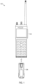
- FIG. 1 depicts a perspective view of an example system 100 that includes a device 102 for throttling current and/or power to peripherals thereof for example from a power source 104. While as depicted the power source 104 and the device 102 are separate from one another, the power source 104 and the device 102 are generally configured to mate such that the power source 104 powers the device 102. However, the device 102 may be provided and/or sold separate from the power source 104.
- the device 102 may comprise a hazardous location (HAZLOC) mobile device
- the power source 104 may comprise a HAZLOC battery, each for use in mines and/or other hazardous locations where sparks and the like may cause explosions and the like.
- HAZLOC hazardous location
- the power source 104 may include a safety circuit (described below) which causes voltage and/or power and/or current to be reduced at terminals of the power source 104 when a safety-related maximum current, and the like, is reached at the power source 104, for example to prevent sparking, and the like, at the terminals
- the device 102 and/or the power source 104 may be adapted for use in non-hazardous locations, and/or may not include a safety circuit and/or the device 102 may not be a mobile device and/or the power source 104 may be a power source other than a battery.
- the power source 104 is removable from the device 102, in other examples, the power source 104 may not be removable from the device 102.
- the device 102 is configured to throttle current and/or power to peripherals thereof, for example to prevent tripping the safety circuit and/or more generally to prevent voltage slumps at terminals of the power source 104.
- throttling current throttling current, though it is understood that such throttling leads to concurrent throttling of power.
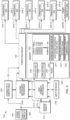
- Fig. 2 depicts a schematic block diagram of components of the device 102, including the power source 104 provided therein with a safety circuit 202 at the power source 104.
- the safety circuit 202 which may be optional, may "trip" and/or reset when a given safety-related maximum current occurs at the power source 104 leading to at least a temporary reduction in power to the components of the device 102.
- the given safety-related maximum current may be a current that causes a voltage at terminals of the power source 104 at which sparking occurs. Such a voltage may be predetermined and stored at a memory of the device 102, described in more detail below
- Fig. 2 some components are described as being connected via power lines to the power source 104 and/or each other, while other components are described as being connected via data lines therebetween and, more specifically, hardware data lines therebetween. Regardless, if a component is not described as having a power line connected thereto, it is nonetheless understood that the power source 104 generally powers such components (e.g. regardless of whether a power line is depicted or not depicted).
- the device 102 comprises various peripherals 204-1, 204-2, 204-3, 204-4...204-N...204-M (e.g. an "N" number of peripherals of a given type of peripheral, which may be transceivers, as described hereafter, with a total "M” number of peripherals).
- the peripherals 204-1, 204-2, 204-3, 204-4...204-N...204-M are interchangeably referred to hereafter, collectively, as the peripherals 204 and, generically, as a peripheral 204. This convention will be used elsewhere in the present specification.
- the device 102 further comprises a sensing circuit 212 configured to: in response to determining that a sensed current from the power source 104 exceeds a threshold current, provide a given interrupt to the throttling circuit 212, for example via the depicted hardware data line 214 therebetween, which may be dedicated to the sensing circuit 212 transmitting interrupts to the throttling circuit 212.
- the sensing circuit 212 may comprise any suitable comparator circuit, and/or comparator circuits, for comparing sensed current to a threshold current.
- throttling of current to the given subset of the peripherals 204 is throttled via the throttling circuit 210 when the sensed current measured by the sensing circuit 212 reaches the threshold current and the sensing circuit 212 provides an interrupt to the throttling circuit 210.
- Such throttling of current to the given subset of the peripherals 204 may ensure that the given subset of the peripherals 204 do not draw current and/or their respective maximum currents.
- throttling of current of the given subset of the peripherals 204 may comprising turning off the given subset of the peripherals 204 and/or turning off associated power amplifiers 206.
- throttling of current of the given subset of the peripherals 204 may comprise controlling the given subset of the peripherals 204, and/or associated power amplifiers 206, to reduce current usage and/or draw a minimum current.
- the remaining peripherals 204 e.g. other than given subset of the peripherals 204 and the presently prioritized peripheral 204 may be allowed to operate "normally" and/or not have current throttled thereto, as a sum of their respective maximum currents is within, and/or is less than, the available current overhead.
- the throttling circuit 210 may cause throttling of current to the given subset of the peripherals 204 accordingly.
- the available current overhead may comprise a difference between the given maximum current and the threshold current.
- the secondary processor 218 may be further configured to determine the given subset of the peripherals 204 to throttle based on the available current overhead and respective predetermined maximum currents used by the peripherals, other than the presently prioritized peripheral 204.
- the memory 220 stores one respective maximum current for each of the peripherals 204
- the memory 220 may store two maximum currents for each of the peripherals 204 which are transceivers: a transmit maximum current for a transmit mode and a receive maximum current for a receive mode.
- a maximum current for a transceiver may differ depending on an operational mode thereof.
- a transceiver may have one maximum current but the given set of peripherals 204 for which throttling of current may occur may depend on whether a transceiver of the presently prioritized peripheral 204 is in a transmit mode or a receive mode. For example, when a transceiver of the presently prioritized peripheral 204 is in a transmit mode one set of the peripherals 204 may be selected as the given set of peripherals 204 for which throttling of current may occur, while, when a transceiver of the presently prioritized peripheral 204 is in a receive mode, another set of the peripherals 204 may be selected as the given set of peripherals 204 for which throttling of current may occur.
- the given set of peripherals 204 may exclude a WiFi transceiver, but when the presently prioritized peripheral 204 is the LTE receiver in a receive mode, the given set of peripherals 204 may include the WiFi transceiver, among other possibilities.
- Such conditions may be provided in the rules 234.
- the primary processor 216 may be further configured to indicate to the sensing circuit 212 to provide the first given interrupt or the second given interrupt to the throttling circuit 210 in response to determining that the sensed current from the power source 104 exceeds the threshold current. For example, when the primary processor 216 selects the presently prioritized peripheral 204 and determines the threshold current, the primary processor 216 may provide an indication of the threshold current to the sensing circuit 212 along with an indication of a type of interrupt to provide to the throttling circuit 210 depending on a mode of the presently prioritized peripheral 204. Furthermore, when the mode of the presently prioritized peripheral 204 changes, the primary processor 216 may again indicate to the sensing circuit 212 a type of associated interrupt to provide to the throttling circuit 210.
- the secondary processor 218 may provide two indications of given subsets of the peripherals 204 which may be throttled to the throttling circuit 210, and/or one for each type of interrupt.
- the presently prioritized peripheral 204 comprises a transceiver a first given set of peripherals 204, for which throttling of current may occur, may be selected for the transmit mode, and a second given set of peripherals 204, for which throttling of current may occur, may be selected for the receive mode.
- the two given sets of peripherals 204 may include different or similar peripherals 204. Indications of both given sets of the peripherals 204 may be provided to the throttling circuit 210 which may cause throttling to one of the two given sets of peripherals 204 depending on a type of interrupt received from the sensing circuit 212.
- the device 102 may include any other suitable components including, but not limited to, a display screen, a location positioning device (e.g. a Global Positioning System device) and the like.
- a location positioning device e.g. a Global Positioning System device
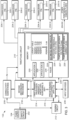
- Fig. 3 Operation of the device 102 is next described with respect to Fig. 3 , Fig. 4 , Fig. 5 , Fig. 6 and Fig. 7 , which are substantially similar to Fig. 2 , with like components having like numbers.
- FIG. 3 depicts the primary processor 216 determining that the peripheral 204-1 is a presently prioritized peripheral 204-1, as describe above; for example, the transceiver of the presently prioritized peripheral 204-1 may be transmitting or receiving video and the other peripherals 204 may not be in use (e.g. other than the other transceivers transmitting or receiving metadata).
- the primary processor 216 determines that a predetermined maximum current of the presently prioritized peripheral 204-1 is 2.1 A, as retrieved from the lookup table 222 (e.g. the maximum current of "Periph1").
- Fig. 4 depicts the primary processor 216 determining a voltage slump-related maximum current (e.g. a "Slump Current") of 4.9A, as described above, and furthermore determining a safety-related maximum current ("P/S Max Current") of 5.0 A retrieved from the memory 220 (e.g. the power source maximum current 228).
- the primary processor 216 selects the smaller of the voltage slump-related maximum current and the safety-related maximum current as a given maximum current 402 (e.g. 4.9 A of the slump-related maximum current is selected).
- Fig. 5 depicts the primary processor 216 determining a threshold current 502 of 2.2 A by adding a predetermined transient current (e.g. of 0.1 A) to the predetermined maximum current of 2.1 A of the presently prioritized peripheral 204-1.
- the primary processor 216 provides the threshold current 502 to the sensing circuit 212 and further provides the available current overhead 504 to the secondary processor 218.
- the secondary processor 218 determines a given subset 506 of the peripherals 204 for which throttling of current may occur by comparing the available current overhead 504 with sums of maximum currents of the peripherals 204, such maximum currents retrieved being from the lookup table 222. For example, as depicted, the secondary processor 218 determines that a sum of maximum currents of the peripherals 204-2, 204-3 is greater than the available current overhead 504. As depicted, the maximum currents 2.2 A and 2.6 A of the peripherals 204-2, 204-3 sum to 2.8 A which is greater than the 2.7 A of the available current overhead 504. The maximum currents 1.2 A and 1.4 A of the remaining peripherals 204-4 and 204-M sum to 2.6A which is less than the 2.7 A of the available current overhead 504.
- the secondary processor 218 selects the peripherals 204-2, 204-3 as the given subset 506 of the peripherals 204 for which throttling of current may occur and provides an indication 508 of the given subset 506 (e.g. as depicted, "2" and "3" respectively indicating peripherals 204-2, 204-3) to the throttling circuit 210 which prepares to throttle the peripherals 204-2, 204-3 of the given subset 506 when an interrupt is received.
- a circuit of the throttling circuit 210 may prepare to control ultra-fast switches to turn off power to the peripherals 204-2, 204-3 (e.g.
- Such preparation may include controlling a plurality of other switches to states where the ultra-fast switches on the power lines to the peripherals 204-2, 204-3 are controlled to turn power off to the peripherals 204-2, 204-3, in response to receiving an interrupt on the hardware data line 214, and the like.
- ultra-fast switches on the power lines to the peripherals 204-2, 204-3 may include FETs with gates that may be open or closed, and the indication 508 may close switches between the hardware data line 214 and gates of FETs of ultra-fast switches on the power lines to the peripherals 204-2, 204-3, which are normally closed, so that an interrupt on the hardware data line 214 may cause such gates to open, disconnecting power between the connectivity subsystem 208 and the peripherals 204-2, 204-3 (e.g. with gates of FETs of ultra-fast switches on the power lines to the other peripherals 204 remaining closed, and corresponding switches between the hardware data line 214 and gates of such FETs remaining open).
- the throttling circuit 210 may cause power to the peripherals 204-2, 204-3 to be turned off in any suitable manner and/or cause current at the peripherals 204-2, 204-3 to be throttled in any suitable manner.
- Fig. 6 depicts the sensing circuit 212 determining that a sensed current 601 (e.g. of 2.3A) is greater than the threshold current 502.
- the sensing circuit 212 provides an interrupt 602 on the hardware data line 214 to the throttling circuit 210.
- the throttling circuit 210 responds to the interrupt 602 by turning off power to the power amplifiers 206-2, 206-3 of the peripherals 204-2, 204-3, represented by indications 604 (e.g. "X") indicating power is off on a power line to the peripherals 204-2, 204-3.
- indications 604 e.g. "X"
- the peripherals 204-2, 204-3 are turned “OFF” and current of the peripherals 204-2, 204-3 is throttled.
- the other peripherals 204 remain on.
- throttling current at the peripherals 204-2, 204-3 are within the scope of the present specification including, but not limited to, throttling maximum current of the peripherals 204-2, 204-3 of the given subset 506, in combination with the unthrottled current of the other peripherals 204, such that a sum of the maximum currents of the unthrottled peripherals 204, and the throttled maximum current of the peripherals 204-2, 204-3 of the given subset 506, does not exceed the available current overhead 504.
- throttling current at the peripherals 204-2, 204-3 may include the throttling circuit 210 transmitting data commands to the peripherals 204-2, 204-3 to cause the peripherals 204-2, 204-3 to reduce current usage.
- Fig. 7 depicts the sensing circuit 212 determining that the sensed current 601 (e.g. of 2.0A) has now dropped to less than the threshold current 502 and, in response, provides an indication 702 of same on the hardware data line 214 to the throttling circuit 210.
- the throttling circuit 210 responds to indication 702 by turning power back on to the power amplifiers 206-2, 206-3 of the peripherals 204-2, 204-3, which turn on power to the peripherals 204-2, 204-3 accordingly and hence stops throttling of current at the peripherals 204-2, 204-3.
- the sensing circuit 212 is further configured to: in response to determining that the sensed current 601 at the power source 104 has fallen back below the threshold current 502, provide a given indication to the throttling circuit 210 to cause the throttling circuit 210 to stop throttling the respective currents to the given subset of the peripherals 204.
- the interrupt 602 may comprise a "high" voltage and/or signal on the hardware data line 214 (e.g. which opens gates of FETs of ultra-fast switches on the data lines to the peripherals 204-2, 204-3), and which is turned off in response to determining that the sensed current 601 at the power source 104 has fallen back below the threshold current 502.
- the indication 702 may comprise the interrupt 602 being turned off.
- the interrupt 602 may be understood to include a voltage on the hardware data line 214 that may cause switches in the throttling circuit 210 to the power amplifiers 206-2, 206-3, to open (or close) and/or otherwise indicate to the power amplifiers 206-2, 206-3 that current thereto is to be throttled.
- the interrupt 602 may be received at the processors 216, 218 to indicate to the processors 216, 218 that the peripherals 204-2, 204-3 (and/or the given subset 506 of the peripherals 204) are being throttled with respect to current and may not be available for usage.
- one or more of the processors 216, 218 may provide an indication of same at a notification device of the device 102, such as at a display screen thereof to notify a user of the device 102 that the peripherals 204-2, 204-3 may be temporarily unavailable for use.
- a notification device such as at a display screen thereof to notify a user of the device 102 that the peripherals 204-2, 204-3 may be temporarily unavailable for use.
- one or more of the processors 216, 218 may also provide an indication of same at a notification device.
- the interrupt 602 received at the processors 216, 218 may have other effects, including, for example, preventing the processor 218 and/or the at least one connectivity subsystem 208 from attempting to use the peripherals 204-2, 204-3 to transmit associated metadata, and the like.
- the sensing circuit 212 may provide the interrupt 602 only when the sensed current 601 is greater than the threshold current 502 for a given time period, which may be on the order of a few microseconds, and the like.
- FIG. 8 depicts a flowchart representative of a process 800 for throttling current and/or power to peripherals.
- the operations of the process 800 of FIG. 8 may correspond at least in part, to machine readable instructions that are executed by the device 102, and specifically the processors 216, 218 of the device 102 implementing the respective applications 230, 232.
- some operations of the process 800 of FIG. 8 may correspond to hardware configurations of the circuits 210, 212.
- the process 800 is one way in which the device 102 may be configured.
- the process 800 of FIG. 8 need not be performed in the exact sequence as shown and likewise various blocks may be performed in parallel rather than in sequence. Accordingly, the components of process 800 are referred to herein as "blocks" rather than "steps.
- the process 800 of FIG. 8 may be implemented on variations of the device 102, as well. For example, while the process 800 is described with respect to specific processors 216, 218 performing certain blocks, such blocks may be understood to be performed by one or more of the processors 216, 218.
- the device 102 determines a presently prioritized peripheral 204 for example as described with respect to Fig. 4 .
- the device 102 determines a threshold current, for example as described with respect to Fig. 5 .
- the threshold current may comprise one or more of: a predetermined maximum current of the presently prioritized peripheral 204; and the predetermined maximum current of the presently prioritized peripheral 204 adjusted by a given amount.
- the device 102 specifically the primary processor 216, provides the threshold current (e.g. an indication of a value thereof) to the sensing circuit 212, for example as described with respect to Fig. 5 .
- the sensing circuit 212 is configured to sense when a sensed current of the power source 104 of the device 102 exceeds a threshold current.
- the device 102 for example the primary processor 216, determines an available current overhead, for example as described with respect to Fig. 5 .
- the device 102 determines a given subset of the peripherals 204 for which throttling of current is to occur based, on the available current overhead, as described with respect to Fig. 5 .
- the available current overhead may comprises a difference between the threshold current and a given maximum current, such that the process 800 may further comprise determining the given subset of the peripherals 204 to throttle based on the available current overhead and respective predetermined maximum currents (e.g. as stored at the memory 220) used by the peripherals 204, other than the presently prioritized peripheral 204-1.
- the given maximum current may comprise a smaller of a safety-related maximum current (e.g. the current 228) that trips the safety circuit 202; and a voltage slump-related maximum current that causes a voltage slump at terminals of the power source 104.
- the device 102 for example the secondary processor 218, provides an indication of the given subset of the peripherals 204, for which throttling of current is to occur, to the throttling circuit 210, as described with respect to Fig. 5 .
- While the blocks 802, 804, 806, 808, 810 and 812 may be implemented at least partially via software implemented by one or more of the processors 216, 218, the following blocks of the process 800 are understood to be implemented in hardware of the circuits 210, 212 and, in particular, ultra-fast switching components.
- the device 102 determines whether a sensed current exceed the threshold current.
- the sensing circuit 212 determines that the sensed current exceeds the threshold current (e.g. a "YES" decision at the block 814)
- the device 102, and specifically the sensing circuit 212 provides the interrupt 602 to the throttling circuit 210 via the hardware data line 214 therebetween; which, at a block 818 causes throttling of current to the given subset of the peripherals 204 (e.g. based on the indication 508 of the given subset 506), as described above with respect to FIG. 6 .
- the presently prioritized peripheral 204-1 may comprise a transceiver, and the given interrupt may be one of a first given interrupt associated with the transceiver in a transmit mode or a second given interrupt associated with the transceiver in a receive mode, and the given subset of the peripherals 204 which for which current is throttled may be dependent on whether the given interrupt is the first given interrupt or the second given interrupt.
- the process 800 may further comprise indicating, at the device 102, for example from the first processor 216, to the sensing circuit 21, to provide the first given interrupt or the second given interrupt to the throttling circuit 210 in response to determining that the sensed current from the power source 104 exceeds the threshold current.
- the peripherals 204 may comprise transceivers, and the throttling circuit 210 causing throttling of the respective currents to the given subset 506 of the peripherals 204 may comprise the throttling circuit 210 causing throttling of the respective currents to power amplifiers 206 of the transceivers.
- determining (e.g. at the block 802) which of the peripherals is the presently prioritized peripheral 204-1 may comprises communicating with the at least one connectivity subsystem 208 of the device 102 over one or more of the data lines, the at least one connectivity subsystem 208 including hardware for the transceivers, and at least a portion of the peripherals 204 may comprise the transceivers.
- the device 102 continues to determine whether the sensed current exceed the threshold current and, in response to the sensing circuit 212 determining that the sensed current from the power source 104 has fallen back below the threshold current(e.g. a "NO" decision at the block 814), at a block 820, the device 102, and specifically the sensing circuit 212, provides, from the sensing circuit 212 to the throttling circuit 210, on the hardware data line 214, therebetween, the given indication 702 which, at a block 820 causes throttling of current to the given subset of the peripherals 204 to stop, as described above with respect to FIG. 7 .
- the threshold current e.g. a "NO" decision at the block 814
- process 800 may be repeated after the block 820 and/or as the presently prioritized peripheral 204 changes, for example as peripherals 204 are used, or not, at the device 102, and/or as the associated threshold current and available current overhead changes, with suitable blocks of the process 800 being reimplemented accordingly.
- the sensing circuit 212 may be correspondingly configured to determine when voltage of the power source 104 reaches such a shutdown threshold voltage 226 (e.g. which, in some examples, may occur prior to a sensed current from the power source exceeding the threshold current. In these examples, the sensing circuit 212 may provide the given interrupt to the throttling circuit 210 via the hardware data line 214 therebetween. Hence, in such examples, the voltage of the power source 104 reaching (e.g.
- shutdown threshold voltage 226 may be another condition under which the device 102 implements the blocks 816, 818, 820), presuming that the processors 216, 218 have previously determined peripherals 205 for which to throttle current, etc., at the blocks 802 to 812.
- a "contains ... a” does not, without more constraints, preclude the existence of additional identical elements in the process, method, article, or apparatus that comprises, has, includes, contains the element.
- the terms “a” and “an” are defined as one or more unless explicitly stated otherwise herein.
- the terms “substantially”, “essentially”, “approximately”, “about” or any other version thereof, are defined as being close to as understood by one of ordinary skill in the art, and in one non-limiting embodiment the term is defined to be within 10%, in another embodiment within 5%, in another embodiment within 1% and in another embodiment within 0.5%.
- a device or structure that is "configured” in a certain way is configured in at least that way, but may also be configured in ways that are not listed.
- Coupled can have several different meanings depending on the context in which these terms are used.
- the terms coupled, coupling, or connected can have a mechanical or electrical connotation.
- the terms coupled, coupling, or connected can indicate that two elements or devices are directly connected to one another or connected to one another through intermediate elements or devices via an electrical element, electrical signal or a mechanical element depending on the particular context.
- processors such as microprocessors, digital signal processors, customized processors and field programmable gate arrays (FPGAs) and unique stored program instructions (including both software and firmware) that control the one or more processors to implement, in conjunction with certain non-processor circuits, some, most, or all of the functions of the method and/or apparatus described herein.
- processors or “processing devices”
- FPGAs field programmable gate arrays
- unique stored program instructions including both software and firmware
- an embodiment can be implemented as a computer-readable storage medium having computer readable code stored thereon for programming a computer (e.g., comprising a processor) to perform a method as described and claimed herein.
- a computer e.g., comprising a processor
- Any suitable computer-usable or computer readable medium may be utilized. Examples of such computer-readable storage mediums include, but are not limited to, a hard disk, a CD-ROM, an optical storage device, a magnetic storage device, a ROM (Read Only Memory), a PROM (Programmable Read Only Memory), an EPROM (Erasable Programmable Read Only Memory), an EEPROM (Electrically Erasable Programmable Read Only Memory) and a Flash memory.
- a computer-usable or computer-readable medium may be any medium that can contain, store, communicate, propagate, or transport the program for use by or in connection with the instruction execution system, apparatus, or device.
- computer program code for carrying out operations of various example embodiments may be written in an object oriented programming language such as Java, Smalltalk, C++, Python, or the like.
- object oriented programming language such as Java, Smalltalk, C++, Python, or the like.
- computer program code for carrying out operations of various example embodiments may also be written in conventional procedural programming languages, such as the "C" programming language or similar programming languages.
- the program code may execute entirely on a computer, partly on the computer, as a stand-alone software package, partly on the computer and partly on a remote computer or server or entirely on the remote computer or server.
- the remote computer or server may be connected to the computer through a local area network (LAN) or a wide area network (WAN), or the connection may be made to an external computer (for example, through the Internet using an Internet Service Provider).
- LAN local area network
- WAN wide area network
- Internet Service Provider for example, AT&T, MCI, Sprint, EarthLink, MSN, GTE, etc.
Landscapes
- Engineering & Computer Science (AREA)
- Theoretical Computer Science (AREA)
- General Engineering & Computer Science (AREA)
- Physics & Mathematics (AREA)
- General Physics & Mathematics (AREA)
- Computer Networks & Wireless Communication (AREA)
- Power Engineering (AREA)
- Signal Processing (AREA)
- Human Computer Interaction (AREA)
- Computer Hardware Design (AREA)
- Computing Systems (AREA)
- Power Sources (AREA)
- Amplifiers (AREA)
Description
- Batteries, and/or other power sources, of intrinsically safe devices, such as mobile devices, and the like, may include a safety circuit which is tripped when power and/or current drawn from the battery reaches a threshold value.
-
US2008178032 discloses a power management system comprising a power management module configured to determine a power draw limit for operating an electronic device by a power source, the power management module configured to control use of power-consuming elements of the electronic device based on a prioritization of the power-consuming elements to limit a power draw by the electronic device from the power source to the power draw limit. -
US2016349829 discloses a method including: obtaining a first value indicative of an amount of power available to a device from a power source, obtaining a second value indicative of an amount of power consumed by the device, and selecting, based on the first value and second value, one or more power consuming functions of the device in order to manage power consumption of the device. - The accompanying figures, where like reference numerals refer to identical or functionally similar components throughout the separate views, together with the detailed description below, are incorporated in and form part of the specification, and serve to further illustrate embodiments of concepts that include the claimed invention, and explain various principles and advantages of those embodiments.
-
FIG. 1 depicts a system that includes device for throttling current and/or power to peripherals thereof, from a power source in accordance with some examples. -
FIG. 2 is a device diagram showing an example structure of the device ofFig. 1 , in accordance with some examples. -
FIG. 3 shows the device ofFig. 1 determining a presently prioritized peripheral and a maximum current thereof, in accordance with some examples. -
FIG. 4 shows the device ofFig. 1 determining a given maximum current of a power source thereof, in accordance with some examples. -
FIG. 5 shows the device ofFig. 1 determining an available current overhead and a given subset of the peripherals to which current may be throttled, in accordance with some examples. -
FIG. 6 shows the device ofFig. 1 throttling current to the given subset of the peripherals in response to a sensed current from the power source exceeds the threshold current, in accordance with some examples. -
FIG. 7 shows the device ofFig. 1 stopping throttling current to the given subset of the peripherals in response to a sensed current from the power source no longer exceeding the threshold current, in accordance with some examples. -
FIG. 8 is a flowchart of a process for throttling current to peripherals, in accordance with some examples. - Skilled artisans will appreciate that elements in the figures are illustrated for simplicity and clarity and have not necessarily been drawn to scale. For example, the dimensions of some of the elements in the figures may be exaggerated relative to other elements to help improve understanding of embodiments of the present disclosure.
- The system, apparatus, and method components have been represented where appropriate by conventional symbols in the drawings, showing only those specific details that are pertinent to understanding the embodiments of the present disclosure so as not to obscure the disclosure with details that will be readily apparent to those of ordinary skill in the art having the benefit of the description herein.
- Batteries, and/or other power sources, of intrinsically safe devices, such as mobile devices, and the like, may include a safety circuit which is tripped when a current and/or power drawn from the battery and/or power source reaches a threshold value. Such devices include various peripherals which draw current and/or power from a power source thereof. Such peripherals may include, but are not limited to, various transceivers, such as cell phone and/or broadband transceivers (e.g. Long Term Evolution (LTE) transceivers, and the like), narrowband transceivers, WiFi transceivers, and the like. Other peripherals may include a camera, a flash for the camera, which may be used as a flashlight, and the like. A particular peripheral may, for a time period, be a most active and/or prioritized peripheral which may lead to a high draw of current and/or power from the power source for the time period. As such, when another peripheral draws current and/or current from the power source, the total current and/or power drawn from the power source, for example in combination with transient currents, and the like, at the device, may cause power and/or current drawn from the battery and/or power source to reach the threshold value, causing the safety circuit to trip and/or reset. Complicating the situation, safety circuits may react within a very small amount of time, such on the order of 5µs. Hence, software based solutions alone may be challenging to implement as they may not respond fast enough (e.g. within 5µs) to prevent tripping of such safety circuits. Alternatively, current drawn from the battery and/or power source may cause a voltage slump at the battery and/or power source. Thus, there exists a need for an improved technical device, system and method for throttling current and/or power to peripherals.
- As such, provided herein is a device that throttles current and/or power to peripherals. The device includes a throttling circuit configured to: in response to receiving a given interrupt (described below), cause throttling of respective currents to a given subset of the peripherals, for example when another prioritized peripheral is drawing power and/or current from a power source of the device that may include a safety circuit. In particular, the device further includes a sensing circuit configured to: in response to determining that a sensed current from the power source exceeds a threshold current, provide the given interrupt to the throttling circuit. Both the throttling circuit and the sensing circuit may comprise ultra-fast electronic switching components which typically respond in less than 5µs (e.g. faster than the safety circuit). As such, when one particular peripheral is a presently prioritized peripheral, power and/or current may be throttled to one or more of the other peripherals via an interrupt provided to the throttling circuit by the sensing circuit to prevent the one or more other peripherals from drawing sufficient power and/or current to trip the safety circuit.
- The threshold current may be based on predetermined maximum current of a presently prioritized peripheral (e.g. for example minus a given factor such as 10% and the like). Selection of which peripherals to throttle may be based on an available current overhead, which may be a difference between the threshold current and a given maximum current. The given maximum current may comprise a smaller of a safety-related maximum current that trips the safety circuit of the power source; and a voltage slump-related maximum current that causes a voltage slump at terminals of the power source. The voltage slump-related maximum current may change as inductance at the power source varies over time due to changes in which peripherals, and/or other components of the device, are drawing power at any given time. Hence, the voltage slump-related maximum current may be determined periodically based on sensed current by the sensing circuit. The selection of which peripherals to throttle may occur by selecting peripherals which have predetermined maximum currents which sum to a value that is less than the available current overhead, and the remaining peripherals are selected as a given subset of the peripherals for which current is throttled .
- An aspect of the present specification provides a device comprising: peripherals powered by a power source; a throttling circuit configured to: in response to receiving a given interrupt, cause throttling of respective currents to a given subset of the peripherals; a sensing circuit configured to: in response to determining that a sensed current from the power source exceeds a threshold current, provide the given interrupt to the throttling circuit via a hardware data line therebetween; a primary processor configured to: determine the threshold current based at least on a predetermined maximum current of a presently prioritized peripheral; and provide the threshold current to the sensing circuit; and a secondary processor configured to: determine the given subset of the peripherals based on an available current overhead.
- Another aspect of the present specification provides a method comprising: determining, at one or more processors of a device, a presently prioritized peripheral of the device; determining, at the one or more processors, a threshold current of the device; providing, via the one or more processors, the threshold current to a sensing circuit of the device, the sensing circuit configured to sense when a sensed current of a power source of the device exceeds the threshold current; determining, at the one or more processors, an available current overhead of the device; determining, at the one or more processors, based on the available current overhead, a given subset of peripherals of the device to current throttle when the sensed current exceeds the threshold current; providing, at the one or more processors, an indication of the given subset of peripherals to a throttling circuit; in response to the sensing circuit sensing that the sensed current of the power source exceeds the threshold current, providing a given interrupt from the sensing circuit to the throttling circuit, via a hardware data line therebetween; and in response to the throttling circuit receiving the given interrupt on the hardware data line, causing throttling, via the throttling circuit, based on the indication of the given subset, throttling of current at the given subset of the peripherals.
- Each of the above-mentioned examples will be discussed in more detail below, starting with example system and device architectures of the system in which the embodiments may be practiced, followed by an illustration of processing blocks for achieving an improved technical method, device, and system for throttling current and/or power to peripherals.
- Example embodiments are herein described with reference to flowchart illustrations and/or block diagrams of methods, apparatus (systems) and computer program products according to example embodiments. It will be understood that each block of the flowchart illustrations and/or block diagrams, and combinations of blocks in the flowchart illustrations and/or block diagrams, can be implemented by computer program instructions unless otherwise indicated. These computer program instructions may be provided to a processor of a general purpose computer, special purpose computer, or other programmable data processing apparatus to produce a special purpose and unique machine, such that the instructions, which execute via the processor of the computer or other programmable data processing apparatus, create means for implementing the functions/acts specified in the flowchart and/or block diagram block or blocks. The methods and processes set forth herein need not, in some embodiments, be performed in the exact sequence as shown and likewise various blocks may be performed in parallel rather than in sequence. Accordingly, the elements of methods and processes are referred to herein as "blocks" rather than "steps."
- These computer program instructions may also be stored in a computer-readable memory that can direct a computer or other programmable data processing apparatus to function in a particular manner, such that the instructions stored in the computer-readable memory produce an article of manufacture including instructions which implement the function/act specified in the flowchart and/or block diagram block or blocks.
- The computer program instructions may also be loaded onto a computer or other programmable data processing apparatus that may be on or off-premises, or may be accessed via the cloud in any of a software as a service (SaaS), platform as a service (PaaS), or infrastructure as a service (IaaS) architecture so as to cause a series of operational blocks to be performed on the computer or other programmable apparatus to produce a computer implemented process such that the instructions which execute on the computer or other programmable apparatus provide blocks for implementing the functions/acts specified in the flowchart and/or block diagram block or blocks. It is contemplated that any part of any aspect or embodiment discussed in this specification can be implemented or combined with any part of any other aspect or embodiment discussed in this specification.
- Further advantages and features consistent with this disclosure will be set forth in the following detailed description, with reference to the drawings.
- Attention is directed to
FIG. 1 , which depicts a perspective view of anexample system 100 that includes adevice 102 for throttling current and/or power to peripherals thereof for example from apower source 104. While as depicted thepower source 104 and thedevice 102 are separate from one another, thepower source 104 and thedevice 102 are generally configured to mate such that thepower source 104 powers thedevice 102. However, thedevice 102 may be provided and/or sold separate from thepower source 104. - As depicted, the
device 102 may comprise a hazardous location (HAZLOC) mobile device, and thepower source 104 may comprise a HAZLOC battery, each for use in mines and/or other hazardous locations where sparks and the like may cause explosions and the like. As such, thepower source 104 may include a safety circuit (described below) which causes voltage and/or power and/or current to be reduced at terminals of thepower source 104 when a safety-related maximum current, and the like, is reached at thepower source 104, for example to prevent sparking, and the like, at the terminals However, in other examples, thedevice 102 and/or thepower source 104 may be adapted for use in non-hazardous locations, and/or may not include a safety circuit and/or thedevice 102 may not be a mobile device and/or thepower source 104 may be a power source other than a battery. Furthermore, while as depicted thepower source 104 is removable from thedevice 102, in other examples, thepower source 104 may not be removable from thedevice 102. - In general, however, the
device 102 is configured to throttle current and/or power to peripherals thereof, for example to prevent tripping the safety circuit and/or more generally to prevent voltage slumps at terminals of thepower source 104. Hereafter, reference will be made to throttling current, though it is understood that such throttling leads to concurrent throttling of power. - Attention is next directed to
Fig. 2 which depicts a schematic block diagram of components of thedevice 102, including thepower source 104 provided therein with asafety circuit 202 at thepower source 104. As mentioned above, thesafety circuit 202, which may be optional, may "trip" and/or reset when a given safety-related maximum current occurs at thepower source 104 leading to at least a temporary reduction in power to the components of thedevice 102. In some examples, the given safety-related maximum current may be a current that causes a voltage at terminals of thepower source 104 at which sparking occurs. Such a voltage may be predetermined and stored at a memory of thedevice 102, described in more detail below - As will become apparent, in
Fig. 2 , some components are described as being connected via power lines to thepower source 104 and/or each other, while other components are described as being connected via data lines therebetween and, more specifically, hardware data lines therebetween. Regardless, if a component is not described as having a power line connected thereto, it is nonetheless understood that thepower source 104 generally powers such components (e.g. regardless of whether a power line is depicted or not depicted). - As depicted, the
device 102 comprises various peripherals 204-1, 204-2, 204-3, 204-4...204-N...204-M (e.g. an "N" number of peripherals of a given type of peripheral, which may be transceivers, as described hereafter, with a total "M" number of peripherals). The peripherals 204-1, 204-2, 204-3, 204-4...204-N...204-M are interchangeably referred to hereafter, collectively, as theperipherals 204 and, generically, as a peripheral 204. This convention will be used elsewhere in the present specification. - As depicted, the peripherals 204-1, 204-2, 204-3, 204-4...204-N comprise "N" number of transceivers and/or radios and/or modems, which may comprise any include, but is not limited to, any suitable combination of a cell phone transceiver, a digital mobile radio (DMR) transceiver, Project 25 (P25) transceiver, a terrestrial trunked radio (TETRA) transceiver, a 3rd Generation Partnership Project (3GPP) transceiver, a Long-Term Evolution (LTE) transceiver, a Global System for Mobile communications (GSM) transceiver, a 5G transceiver, a 5G transceiver (e.g., a transceiver for use with network architecture compliant with, for example, the 3GPP Technical Specification (TS) 23 specification series and/or a new radio (NR) air interface compliant with the 3GPP TS 38 specification series) a Bluetooth transceiver, a Wi-Fi transceiver (e.g., operating in accordance with an IEEE 802.11 standard (e.g., 802.11a, 802.11b, 802.11g), a Worldwide Interoperability for Microwave Access (WiMAX) transceiver, and/or another similar type of wireless transceiver configurable to communicate via a wireless radio network
- As depicted, a peripheral 204-1, 204-2, 204-3, 204-4...204-N (e.g. transceivers) comprises a respective power amplifier 206-1, 206-2, 206-3, 206-4...206-N (
e.g. power amplifiers 206 and/or apower amplifier 206, indicated as "P/A" inFig. 2 ) which amplify power from the power source to power the peripherals 204-1, 204-2, 204-3, 204-4...204-N (e.g. transceivers). Hence, in general, thepower source 104 powers thepower amplifiers 206, as described in more detail below. Furthermore, it is understood that the peripherals 204-1, 204-2, 204-3, 204-4...204-N (e.g. transceivers) may operate in a transmit mode or a receive mode, for example to respectively transmit or receive signals and/or data. - As depicted, the
device 102 further comprises at least oneconnectivity subsystem 208 which may include other hardware for the transceivers of the peripherals 204-1...204-N including, but not limited to, wireless input/output (I/O) interfaces, modulators/demodulators and the like. As depicted, there is a power line from thepower source 104 to the at least oneconnectivity subsystem 208 which may distribute and/or otherwise control power to thepower amplifiers 206, for example via athrottling circuit 210. Put another way, while the transceivers of the peripherals 204-1, 204-2, 204-3, 204-4...204-N and thepower amplifiers 206 are depicted as separate from at least oneconnectivity subsystem 208, the transceivers of the peripherals 204-1, 204-2, 204-3, 204-4...204-N may be components of the at least oneconnectivity subsystem 208 which, for example, may control a respective transceiver between a transmit mode or a receive mode, and the like. - Hence, while one
connectivity subsystem 208 is depicted, theconnectivity subsystem 208 may include any suitable number ofconnectivity subsystems 208, for example oneconnectivity subsystem 208 per transceiver type, to control wireless communications at thedevice 102. In a particular example thedevice 102 may include a transceiver, and associated input devices, used to push-to-talk (PTT) wireless communications. When a PTT input device is actuated (e.g. a PTT button), an associatedPTT connectivity subsystem 208 may control a respective transceiver into a transmit mode, with an associatedpower amplifier 206 controlled by the associatedPTT connectivity subsystem 208 to provide sufficient power to transmit in the transmit mode; otherwise, when the PTT input device is unactuated, the associatedPTT connectivity subsystem 208 may control the respective transceiver into a receive mode, with the associatedpower amplifier 206 controlled by the associatedPTT connectivity subsystem 208 to provide sufficient power to receive in the receive mode, which may be a different amount of power than in the transmit mode. In yet further examples, the associatedPTT connectivity subsystem 208 may control the respective transceiver into a standby mode in which wireless metadata is received to schedule PTT transmit and receive time slots, and the like, with the associatedpower amplifier 206 controlled by the associatedPTT connectivity subsystem 208 to provide sufficient power to receive such wireless metadata in the standby mode. - However, a transceiver and/or an associated
power amplifier 206 may be controlled in different ways and/or into other modes, which may depend on a type of data being transmitted or received. For example, video data being transmitted or received may use more power than audio data, among other possibilities, with an associatedpower amplifier 206 controlled accordingly. - Hence, to control the
power amplifiers 206, the least oneconnectivity subsystem 208 is depicted has including an "N" (e.g. "/N") number of connections to thepower amplifiers 206, via athrottling circuit 210 described below) over which power to thepower amplifiers 206 may be provided. In some examples, power provided to thepower amplifiers 206 may depend on a mode in which a respective transceiver is to be used. - As depicted, other peripherals 204 (e.g. the peripherals labelled as "204-M" and which will hence be referred to hereafter as the peripherals 204-M) may comprise peripherals other than transceivers for example, as depicted, a camera, a camera flash, a flashlight among other possibilities. Hence, the
device 102 is understood to include any suitable number ofperipherals 204 of any suitable types; in particular, a peripheral 204 may be understood to include any type of device and/or auxiliary device that may be provided at thedevice 102 to provide and/or expand functionality thereof. While the other peripherals 204-M are depicted withoutpower amplifiers 206, such peripherals 204-M may include power amplifiers. - Furthermore, while connectivity (e.g. communication functionality) of the
device 102 is described with respect to wireless communications, in some examples, thedevice 102 may include functionality for wired communication and/or may include only components for wired communication and/or may not be configured for communication. In these last examples, thedevice 102 may include the peripherals 204-M, and not the peripherals 204-1...204-N. - As depicted, the
device 102 further comprises thethrottling circuit 210 configured to: in response to receiving a given interrupt (described below), cause throttling of respective currents to a given subset of theperipherals 204. For example, as depicted, there are respective hardware connections between the throttlingcircuit 210 and theperipherals 204 which may be used to turn off respective power, from the at least oneconnectivity subsystem 208, to theperipherals 204 based on interrupts. - In particular, the
throttling circuit 210 may comprise switches, such as ultra-fast switches, and the like, which may switch a respective hardware power connection, between the at least oneconnectivity subsystem 208 and arespective power amplifier 206, on or off, to throttle current usage, and the like, at arespective power amplifier 206. Put another way, thethrottling circuit 210 may comprises respective hardware switches to cause throttling of the respective currents to the given subset of theperipherals 204 as described below (e.g. a hardware switch per data line to the peripherals 204) and such hardware switches may comprise ultra-fast switches, and the like. - However, the
throttling circuit 210 may further comprise switches (e.g. ultra-fast switches) to turn power to the other types of peripheral 204-M on or off and/or otherwise cause throttling of respective currents to the other types of peripherals 204-M. - While present examples are described with respect to power to a peripheral 204 being turned on or off, to throttle current used by a peripheral, in other examples the hardware switches of the
throttling circuit 210 may limit power and/or current to a peripheral 204 to a non-zero, but non-maximum value. For example, the hardware switches of thethrottling circuit 210 may reduce power and/or current to a peripheral 204 by 10%, 50%, 80%, among other possibilities. In yet further examples, thethrottling circuit 210 may be configured to throttle current to a peripheral 204 may transmitting a data command to a peripheral 204 to cause the peripheral 204 to throttle current thereto; in these examples the connections between the connectivity subsystem and thethrottling circuit 210, as well as the connections between the throttlingcircuit 210 and the peripherals, may comprise data lines, with power being provided to theperipherals 204 via other power connections to thepower source 104. - In the depicted example, at least a portion of the peripherals 204 (e.g. four peripherals 204) comprise transceivers, with the at least one
connectivity subsystem 208 including hardware for the transceivers (e.g. and which may include the power amplifiers 206). In these examples, thethrottling circuit 210 be configured to cause throttling of respective currents to a given subset of theperipherals 204 by causing throttling the respective currents to thepower amplifiers 206. - The interrupts used to control the
throttling circuit 210, along with whichperipherals 204 to throttle, are described below, however, different interrupts may be provided to thethrottling circuit 210 to cause thethrottling circuit 210 to throttle different subset of theperipherals 204 which may depend, for example, on a mode in which a peripheral 204 is currently being used (e.g. a transmit mode or a receive mode). Such different interrupts are also described below. - As depicted, the
device 102 further comprises asensing circuit 212 configured to: in response to determining that a sensed current from thepower source 104 exceeds a threshold current, provide a given interrupt to thethrottling circuit 212, for example via the depictedhardware data line 214 therebetween, which may be dedicated to thesensing circuit 212 transmitting interrupts to thethrottling circuit 212. As such, thesensing circuit 212 may comprise any suitable comparator circuit, and/or comparator circuits, for comparing sensed current to a threshold current. - As depicted, the
sensing circuit 212 is tapped into a power line from thepower source 104, and thesensing circuit 212 is understood to include any suitable combination of hardware components for sensing current on the power line from thepower source 104. In particular, thesensing circuit 212 may be connected "close" to the terminals of thepower source 104 and be configured to sense current from thepower source 104 and/or changes to current being drawn from the power source (e.g. by the peripherals 204) as quickly as possible. - In general, the
circuits - As depicted, the
device 102 further comprises a first processor 216 (interchangeably referred to hereafter as a primary processor 216) and a second processor 218 (interchangeably referred to hereafter as a secondary processor 218). - In general, the
processors processors device 102 is described with respect to twoprocessors processors - In particular, the
primary processor 216 may comprise a processor for thedevice 102 which implements general functionality therefor, such as an operating system, and the like, as well as the functionality described herein, as well as operating the peripherals 204-M that are not transceivers. - In contrast, the
secondary processor 218 may comprise a processor that implements general functionality associated with the at least oneconnectivity subsystem 208 and the peripherals 204-N that are transceivers and/or which may be at least partially dedicated to implementing functionality on behalf of the least oneconnectivity subsystem 208, as well as the functionality described herein. However, input for operating the transceivers may be received via the primary processor 216 (e.g. viainput devices 236 described below) and theprocessors device 102 with thesecondary processor 218 performing connectivity processing functionality on behalf of theprimary processor 216; hence, thesecond processor 218 may be "secondary" to thefirst processor 216. - As depicted, the
processors sensing circuit 212 for example on thehardware data line 214 between thecircuits sensing circuit 212 transmitting interrupts to the throttling circuits. As such, when thesensing circuit 212 transmits an interrupt to thethrottling circuit 210, theprocessors throttling circuit 210 is causing (and/or is about to cause) throttling of respective currents to a given subset of theperipherals 204. - However, as depicted, the
primary processor 216 is in communication with thesensing circuit 212 and thesecondary processor 218 via respective data lines (e.g. depicted as double-ended arrows therebetween), which may comprise data lines of a common data and address bus, and the like, of thedevice 102. Such a common data and address bus may be used to exchange data between components of thedevice 102. Thehardware data line 214 may be separate from a common data and address bus of thedevice 102. - Furthermore, as depicted, there are data lines (e.g. also depicted as double-ended arrows therebetween) between the
secondary processor 218 and the at least oneconnectivity subsystem 208, and thesecondary processor 218 and thethrottling circuit 210, which may also comprise data lines of the common data and address bus, and the like, of thedevice 102. - The
primary processor 216 may be generally configured to determine a threshold current (e.g. at which thesensing circuit 212 provides a given interrupt) based at least on a predetermined maximum current of a presently prioritized peripheral 204; and provide the threshold current to the sensing circuit 212 (e.g. on a data line therebetween). A presently prioritized peripheral 204 and a predetermined maximum current is described in more detail below however, in general, the threshold current may comprise one or more of: the predetermined maximum current of the presently prioritized peripheral 204; and the predetermined maximum current of the presently prioritized peripheral adjusted by a given amount; for example, the predetermined maximum current of the presently prioritized peripheral 204 may be reduced by 5%, 10%, 15%, among other possibilities. - The
secondary processor 218 is generally configured to determine the given subset of the peripherals 204 (e.g. for which respective currents are caused to throttle by the throttling circuit 210) based on an available current overhead which is determined by theprimary processor 216 and provided to thesecondary processor 218 on a data line therebetween. - As will be described in more detail below, a given maximum current of the
power source 104 may be determined by theprimary processor 216, and the given maximum current may comprise: a smaller of a safety-related maximum current that trips thesafety circuit 202; and a voltage slump-related maximum current that causes a voltage slump at terminals of thepower source 104. - As will be further described below, the available current overhead may comprises a difference between the threshold current and the given maximum current, and the secondary processor 217 may be further configured to determine the given subset of the peripherals 204 (e.g. for which throttling of current is to occur by the throttling circuit 210) based on the available current overhead and respective predetermined maximum currents used by the peripherals, other than the presently prioritized peripheral. Furthermore, the
secondary processor 218 may provide an indication, and the like, of the given subset of theperipherals 204, to which current is to be throttled, to thethrottling circuit 210, which responds accordingly when an interrupt is received from thesensing circuit 212. - As depicted, the
device 102 further comprises amemory 220 which stores a lookup table 222, and the like, storing respective maximum currents of theperipherals 204. For example, as depicted a first peripheral (e.g. "Periph1" such as the peripheral 204-1) may have a maximum current of 2.1 Amps, a second peripheral (e.g. "Periph2" such as the peripheral 204-2) may have a maximum current of 2.2 A, etc. As depicted, the lookup table stores a respective maximum current for each peripheral 204 for which thethrottling circuit 210 may cause throttling of current thereto. Such maximum currents may be provisioned at thememory 220 at a factory and the like. Furthermore, such maximum currents may be stored in any suitable format other than a lookup table. Hence, generally, thedevice 102 is understood to comprise thememory 220 storing respective predetermined maximum currents used by theperipherals 204, including a predetermined maximum current of a presently prioritized peripheral 204. In other words, one of theperipherals 204, for which thememory 220 stores predetermined maximum currents, may be selected as a presently prioritized peripheral 204, described in more detail below. In particular, the predetermined maximum currents stored at thememory 220 may comprise maximum root mean square (RMS) currents of theperipherals 204, but may comprise the predetermined maximum currents in any suitable format. - As depicted, the
memory 220 further stores parameters associated with thedevice 102 and/or thepower source 104 which may be measured at the device 102 (e.g. via the sensing circuit 212) and/or read from the power source 104 (e.g. by theprocessor 216, and the like, presuming there is a data line between theprocessor 216 and the power source 104) and/or provisioned at the memory 220 (e.g. at a factory, and the like). Such parameters may include, but are not limited to: an estimated resistance 224 (e.g. a measured inductance) of thepower source 104, which is measured periodically, as described below: ashutdown threshold voltage 226, which may be provisioned at thememory 220; amaximum voltage 227 that may be read from the power source 104 (e.g. from a memory thereof, not depicted); and a maximum current 228 of thepower source 104, which may also be read from thepower source 104. The maximum current 228 may comprise a safety-related maximum current at which thesafety circuit 202 trips, and the like. - In general, the estimated
resistance 224 may be determined by theprimary processor 216 controlling thedevice 102 into an idle mode in which current from drawn from thepower source 104 is primarily transient currents, which is measured by the sensing circuit 212 (e.g. thesensing circuit 212 may measure RMS currents at the terminals of the power source 104). Using Kirchoff's Law (e.g. V=IR, where "V" is voltage, "I" is current" and "R" is resistance) theresistance 224 may be estimated from the known power sourcemaximum voltage 227 and the measured current. In general, the estimatedresistance 224 represents a resistance and/or inductance estimated at the terminals of thepower source 104 due toactive peripherals 204 and/or other components, connected to thepower source 104 at any given time though, in the idle mode, suchactive peripherals 204 may be controlled into a state where minimum power is drawn from thepower source 104. As will be explained in more detail below, once theresistance 224 is estimated (e.g. which may change over time), a voltage slump-related maximum current may be estimated using theshutdown threshold voltage 226 and Kirchoff's Law. In particular, theshutdown threshold voltage 226 may be a value that has been predetermined and stored at thememory 220 at a factory and/or in a provisioning mode of thedevice 102. - Furthermore, the estimated
resistance 224 may be determined periodically, for example every few minutes, and the like, and/or during periods of minimal activity at thedevice 102 and/or at the peripherals 204 (e.g. when the transceivers of theperipherals 204 are "connected" to a respective network, but not transmitting or receiving data other than metadata, which may also be the conditions into which such transceivers are controlled in an idle mode). - Alternatively, or in addition, the
sensing circuit 212 may be configured to measure one or more of resistance and voltage at the terminals of thepower source 104 in addition to, or alternatively to, current, with associated currents (e.g. such as a voltage slump-related maximum current) determined from measured resistance and voltage using Kirchoff's Law. - Regardless, it is hence understood that the
sensing circuit 212 may include an analog-to-digital converter (ADC) configured to convert measured currents (e.g. and/or resistance and/or voltage) to digital indications of same, which may be provided to theprimary processor 216 via a data line to implement functionality as described herein. Thesensing circuit 212 may include a digital-to-analog converter (DAC) configured to convert received digital values (e.g. such as a threshold current received from theprimary processor 216 via a data line) to analog indications of same, which may be used by comparators of thesensing circuit 212 to determine when a sensed current exceeds the received threshold current. - As depicted, the
memory 220 is understood to include any suitable non-transitory machine readable medium that stores machine readable instructions to implement one or more programs or applications such as theapplications FIG. 2 , programming instructions (e.g., machine readable instructions) that implement the functional teachings of thedevice 102 as described herein are maintained, persistently, at thememory 220 and used by theprocessors - For example, the
memory 220 may further store afirst application 230 which may comprise instructions which, when implemented by theprimary processor 216, causes theprimary processor 216 to: determine the threshold current based at least on a predetermined maximum current of a presently prioritized peripheral 204; and provide the threshold current to thesensing circuit 210, described in more detail herein. - Similarly, as depicted, the
memory 220 may further store asecond application 232 which may comprise instructions which, when implemented by thesecondary processor 218, causes thesecondary processor 218 to: determine the given subset of theperipherals 204 based on an available current overhead, described in more detail herein. - In some examples, the
memory 220further stores rules 234 which may be used by thesecondary processor 218, in conjunction with thesecond application 232, to determine the given subset of theperipherals 204. In particular, therules 234 may be user-configured and/or preconfigured, and indicate whichperipherals 204 are to be preferentially current throttled when another peripheral 204 is a presently prioritized peripheral 204. However, therules 234 may further indicate which of theperipherals 204 may be selected as a presently prioritized peripheral 204, for example when more than one of theperipherals 204 is presently active, and the like. - The term "presently prioritized peripheral" as used herein may include a peripheral 204 that is presently most active, such as a transceiver transmitting or receiving the most data and/or using the most power, which may be determined by the
secondary processor 218 monitoring activity at the at least oneconnectivity subsystem 208. However, a peripheral 204 that is presently most active may include any of theperipherals 204 that are currently being operated to perform an associated function and/or using the most power. - However, term "presently prioritized peripheral" as used herein may additionally, and/or alternatively, include a peripheral 204 selected on the basis of other conditions which may include, but is not limited to input from one or
more input devices 236 at thedevice 102. For example,such input devices 236 may include, but are not limited to the aforementioned PTT button and/or any other combination of touch screens, buttons (e.g. which may be physical or electronic as provided at a touch screen), knobs, and the like. User input fromsuch input devices 236 may be used to select a given peripheral 204 to perform an associated function at thedevice 102; such a given peripheral 204 may hence be selected as the presently prioritized peripheral 204. - However, in some examples, a selected peripheral 204 (e.g. as selected via user input) may consume less power and/or be less presently active than another peripheral; in such examples, the
rules 234 may be used to resolve such conflicts as to which peripheral 204 to select as a presently prioritized peripheral 204. For example, a camera being currently operated may use less power and/or be less active than a transceiver, as a transceiver may "constantly" be transmitting or receiving metadata while the camera may only receive input intermittently; however, in this example, as the camera is presently being used (e.g. an associated application thereof is being processed by the primary processor 216), and as the transceiver is only transmitting or receiving metadata, the camera may be selected as the presently prioritized peripheral 204. In other examples, an LTE and/or 5G transceiver may be presently being used to transmit or receive video while a WiFi transceiver is operational but being used to browse via an associated browser application processed by theprimary processor 216; in such examples, the peripheral 204 that includes the LTE and/or 5G transceiver may be selected as the presently prioritized peripheral 204 by virtue of transmitting or receiving video. However, therules 234 may be configured in any particular manner to select the presently prioritized peripheral 204, and which may be user configured and/or provisioned at thememory 220, for example at a factory and/or installed by an entity managing thedevice 102. - In some examples, the
primary processor 216 may determine which of theperipherals 204 is presently prioritized, at least based on activity of the at least oneconnectivity subsystem 208, determined by theprocessors connectivity subsystem 208 may be in communication with thesecondary processor 218 and theprimary processor 216 via one or more data lines (e.g. as depicted theprimary processor 216 may be in communication with at least oneconnectivity subsystem 208 via the secondary processor 218), and theprimary processor 216 may be further configured to determine which of theperipherals 204 is the presently prioritized peripheral 204 by communicating with the at least oneconnectivity subsystem 208 over one or more of the data lines and thesecondary processor 218. Indeed, theprimary processor 216 may receive any suitable data from thesecondary processor 218 and/or the at least onecommunication subsystem 208 to determine activity, and the like, at the transceivers of the peripherals 204-N, and may further monitor activity of the other peripherals 204-M and select a presently prioritized peripheral 204 accordingly. - Hence, the
primary processor 216 is understood to determine a presently prioritized peripheral 204 and further determine a predetermined maximum current of the presently prioritized peripheral 204 by retrieving the predetermined maximum current of the presently prioritized peripheral 204 from the lookup table 222, and the like. For example, theprimary processor 216 may determine that the transceiver of the peripheral 204-1 is the presently prioritized peripheral 204 and retrieve the value "2.1 A" from the lookup table 222. - The
primary processor 216 is generally configured to determine a threshold current using, for example, the predetermined maximum current of the presently prioritized peripheral 204 as retrieved from thememory 220. In some examples, the threshold current may be set to the predetermined maximum current of the presently prioritized peripheral 204. In other examples, the threshold current may be set to the predetermined maximum current of the presently prioritized peripheral adjusted by a given amount, such as reduced by 5%, 10%, 15% among other possibilities. In general, the threshold current is selected as a value of current at which throttling of current is to occur for a given subset of theperipherals 204 to prevent theperipherals 204 from drawing a current that might exceed a given maximum current (e.g. in the event that the given subset of theperipherals 204 draw their respective maximum currents). In some examples, the threshold current may comprise the predetermined maximum current of the presently prioritized peripheral 204 (e.g. adjusted or not adjusted) with predetermined transient currents of thedevice 102 added thereto (e.g. transient currents of thedevice 102 measured in an idle mode); hence the threshold current may comprise the predetermined maximum current of the presently prioritized peripheral 204adjusted based on such transient currents. - Furthermore, the threshold current may be determined periodically by the
primary processor 216 and/or for example as a presently prioritized peripheral 204 changes (e.g. asdifferent peripherals 204 become more active or less active relative to other peripherals 204). As the threshold current changes, theprimary processor 216 may provide the threshold current to thesensing circuit 212. - In some examples, the given maximum current may comprise the maximum current 228 of the
power source 104 retrieved from thememory 220. - Alternatively, the given maximum current may comprise a voltage slump-related maximum current that causes a voltage slump at terminals of the power source. For example, the
primary processor 216 may use the periodically determinedestimated resistance 224, the predeterminedshutdown threshold voltage 226 and Kirchoff's law, to determine such a voltage slump-related maximum current which may be less than the maximum current 228 of thepower source 104. In particular, theshutdown threshold voltage 226 may represent a given slump voltage of the power source 104 (e.g. a voltage to which thepower source 104 may slump without generally adversely affecting the operation of thedevice 102, though it is generally preferred to operate thedevice 102 without a voltage slump) below which thedevice 102 may shut down. Furthermore, in some examples, thesensing circuit 212 may be correspondingly configured to determine when voltage of thepower source 104 reaches such ashutdown threshold voltage 226. - In particular, when a plurality of
peripherals 204 of thedevice 102 are drawing current simultaneously, there is a possibility that all suchoperational peripherals 204 may draw their respective maximum currents simultaneously, which may cause current output by thepower source 104 to reach the maximum current 228, causing thesafety circuit 202 to trip and/or which may cause current output by thepower source 104 to reach theshutdown threshold voltage 226. - In general, the
primary processor 216 may select, as the given maximum current, the smaller of the safety-related maximum current 228 that trips thesafety circuit 202 and the voltage slump-related maximum current that causes a voltage slump at terminals of the power source 104 (e.g. as determined periodically using the periodically determinedestimated resistance 224 and the preconfigured shutdown threshold voltage 226). Put another way, both of the safety-related maximum current 228 and the voltage slump-related maximum current may cause brownouts, and the like, at thedevice 102 and theprimary processor 216 determines a threshold current from the smaller of the two currents selected as the given maximum current, which is used to prevent theperipherals 204 from drawing the safety-related maximum current 228 that trips thesafety circuit 202 and/or the voltage slump-related maximum current from thepower source 104, as described hereafter. - However, in some examples, the given maximum current may comprise the selected safety-related maximum current 228 or the voltage slump-related maximum current reduced, for example by 5% or 10% or another factor, for example to prevent the
peripherals 204 from drawing the safety-related maximum current 228, reduced by such a factor, and/or the voltage slump-related maximum current from thepower source 104, reduced by such a factor. However, such a reduction may be optional. - Hence, in general, the
primary processor 216 may further determine the available current overhead in thedevice 102, which may be determined periodically and/or as the threshold current changes and/or as a presently prioritized peripheral 204 changes. - For example, the
primary processor 216 may periodically determine the threshold current and correspondingly determine the given maximum current as described above. However, such determination may also be decoupled, as, for example, the estimatedresistance 224 may change at a slower rate than does activity of theperipherals 204. - In particular, while a presently prioritized peripheral 204 may not be drawing the predetermined maximum current, there is a possibility that the presently prioritized peripheral 204 may draw the predetermined maximum current, and a value of the threshold current reflects this situation, while the given maximum current represents either the power source maximum current 228 (e.g. which may not change) or a voltage slump-related maximum current which may change slowly compared to activity of the
peripherals 204. - Regardless, the available current overhead in the
device 102 may comprise a value of the given maximum current minus the value for the threshold current. In other words, the available current overhead represents an amount of additional current that may be available to operateother peripherals 204 without exceeding the given maximum current, assuming that the presently prioritized peripheral 204 may draw its predetermined maximum current. - As such, a given subset of the
peripherals 204 is selected, by thesecondary processor 218, the given subset of theperipherals 204 comprising a subset of theperipherals 204 that, when operated at their respective maximum currents, might cause the current drawn from thepower source 104 to exceed the given maximum current. For example, a sum of their respective maximum currents may exceed the available current overhead. Alternatively, the given subset of theperipherals 204 may be selected by first selecting another subset of theperipherals 204 that, when operated at their respective maximum currents, will not cause the current drawn from thepower source 104 to exceed the given maximum current; the remainingperipherals 204 may comprise the given subset of theperipherals 204. - As such, current to the given subset of the
peripherals 204 is throttled via thethrottling circuit 210 when the sensed current measured by thesensing circuit 212 reaches the threshold current and thesensing circuit 212 provides an interrupt to thethrottling circuit 210. Such throttling of current to the given subset of theperipherals 204 may ensure that the given subset of theperipherals 204 do not draw current and/or their respective maximum currents. In some of these examples, throttling of current of the given subset of theperipherals 204 may comprising turning off the given subset of theperipherals 204 and/or turning off associatedpower amplifiers 206. In other examples, throttling of current of the given subset of theperipherals 204 may comprise controlling the given subset of theperipherals 204, and/or associatedpower amplifiers 206, to reduce current usage and/or draw a minimum current. Regardless, the remaining peripherals 204 (e.g. other than given subset of theperipherals 204 and the presently prioritized peripheral 204) may be allowed to operate "normally" and/or not have current throttled thereto, as a sum of their respective maximum currents is within, and/or is less than, the available current overhead. - In some examples, the
secondary processor 218 may determine the given subset of theperipherals 204 for which current is to be throttled by determining combinations of theperipherals 204 which, when their respective maximum currents are added together, exceed the available current overhead. Alternatively, such combinations of theperipherals 204 may have been predetermined and stored at therules 234. Regardless, thesecondary processor 218 may provide an indication of the given subset of theperipherals 204 for which current is to be throttled, to thethrottling circuit 210. - When an interrupt is received from the
sensing circuit 212, for example when a sensed current exceeds the threshold current, thethrottling circuit 210 may cause throttling of current to the given subset of theperipherals 204 accordingly. - Put another way, the available current overhead may comprise a difference between the given maximum current and the threshold current. Furthermore, the
secondary processor 218 may be further configured to determine the given subset of theperipherals 204 to throttle based on the available current overhead and respective predetermined maximum currents used by the peripherals, other than the presently prioritized peripheral 204. - Furthermore, the
sensing circuit 212 may be configured to transmit different types of interrupts, and/or the given subset of theperipherals 204, for which current may be throttled, may depend on a mode of the presently prioritized peripheral 204. For example, when the presently prioritized peripheral 204 comprises a transceiver, a given interrupt provided thesensing circuit 212 may be one of a first given interrupt associated with the transceiver in a transmit mode or a second given interrupt associated with the transceiver in a receive mode; in these examples, the given subset of theperipherals 204 for which throttling of current may occur may be dependent on whether the given interrupt is the first given interrupt or the second given interrupt. - For example, while as depicted the
memory 220 stores one respective maximum current for each of theperipherals 204, in other examples thememory 220 may store two maximum currents for each of theperipherals 204 which are transceivers: a transmit maximum current for a transmit mode and a receive maximum current for a receive mode. In other words, a maximum current for a transceiver may differ depending on an operational mode thereof. - However, in other examples, a transceiver may have one maximum current but the given set of
peripherals 204 for which throttling of current may occur may depend on whether a transceiver of the presently prioritized peripheral 204 is in a transmit mode or a receive mode. For example, when a transceiver of the presently prioritized peripheral 204 is in a transmit mode one set of theperipherals 204 may be selected as the given set ofperipherals 204 for which throttling of current may occur, while, when a transceiver of the presently prioritized peripheral 204 is in a receive mode, another set of theperipherals 204 may be selected as the given set ofperipherals 204 for which throttling of current may occur. For example, when the presently prioritized peripheral 204 is an LTE receiver in a transmit mode, the given set ofperipherals 204 may exclude a WiFi transceiver, but when the presently prioritized peripheral 204 is the LTE receiver in a receive mode, the given set ofperipherals 204 may include the WiFi transceiver, among other possibilities. Such conditions may be provided in therules 234. - Hence, in some examples, the
primary processor 216 may be further configured to indicate to thesensing circuit 212 to provide the first given interrupt or the second given interrupt to thethrottling circuit 210 in response to determining that the sensed current from thepower source 104 exceeds the threshold current. For example, when theprimary processor 216 selects the presently prioritized peripheral 204 and determines the threshold current, theprimary processor 216 may provide an indication of the threshold current to thesensing circuit 212 along with an indication of a type of interrupt to provide to thethrottling circuit 210 depending on a mode of the presently prioritized peripheral 204. Furthermore, when the mode of the presently prioritized peripheral 204 changes, theprimary processor 216 may again indicate to the sensing circuit 212 a type of associated interrupt to provide to thethrottling circuit 210. - Put another way, the
primary processor 216 may be further configured to indicate to thesensing circuit 212 to provide the first given interrupt or the second given interrupt to thethrottling circuit 210 in response to determining that the sensed current from thepower source 104 exceeds the threshold current. - Furthermore, the
secondary processor 218 may provide two indications of given subsets of theperipherals 204 which may be throttled to thethrottling circuit 210, and/or one for each type of interrupt. Continuing with the example above, when the presently prioritized peripheral 204 comprises a transceiver a first given set ofperipherals 204, for which throttling of current may occur, may be selected for the transmit mode, and a second given set ofperipherals 204, for which throttling of current may occur, may be selected for the receive mode. The two given sets ofperipherals 204 may include different orsimilar peripherals 204. Indications of both given sets of theperipherals 204 may be provided to thethrottling circuit 210 which may cause throttling to one of the two given sets ofperipherals 204 depending on a type of interrupt received from thesensing circuit 212. - It is understood that the
device 102 may include any other suitable components including, but not limited to, a display screen, a location positioning device (e.g. a Global Positioning System device) and the like. - Operation of the
device 102 is next described with respect toFig. 3 ,Fig. 4 ,Fig. 5 ,Fig. 6 andFig. 7 , which are substantially similar toFig. 2 , with like components having like numbers. - Attention is first directed to
Fig. 3 which depicts theprimary processor 216 determining that the peripheral 204-1 is a presently prioritized peripheral 204-1, as describe above; for example, the transceiver of the presently prioritized peripheral 204-1 may be transmitting or receiving video and theother peripherals 204 may not be in use (e.g. other than the other transceivers transmitting or receiving metadata). As such, theprimary processor 216, determines that a predetermined maximum current of the presently prioritized peripheral 204-1 is 2.1 A, as retrieved from the lookup table 222 (e.g. the maximum current of "Periph1"). - Attention is next directed to
Fig. 4 which depicts theprimary processor 216 determining a voltage slump-related maximum current (e.g. a "Slump Current") of 4.9A, as described above, and furthermore determining a safety-related maximum current ("P/S Max Current") of 5.0 A retrieved from the memory 220 (e.g. the power source maximum current 228). As such, theprimary processor 216 selects the smaller of the voltage slump-related maximum current and the safety-related maximum current as a given maximum current 402 (e.g. 4.9 A of the slump-related maximum current is selected). - Attention is next directed to
Fig. 5 which depicts theprimary processor 216 determining a threshold current 502 of 2.2 A by adding a predetermined transient current (e.g. of 0.1 A) to the predetermined maximum current of 2.1 A of the presently prioritized peripheral 204-1. Theprimary processor 216 further determines an availablecurrent overhead 504 of 2.7A by subtracting the threshold current 502 from the given maximum current 402 (e.g. 4.9A-2.2A= 2.7A). - The
primary processor 216 provides the threshold current 502 to thesensing circuit 212 and further provides the availablecurrent overhead 504 to thesecondary processor 218. - As also depicted in
Fig. 5 , thesecondary processor 218 determines a givensubset 506 of theperipherals 204 for which throttling of current may occur by comparing the availablecurrent overhead 504 with sums of maximum currents of theperipherals 204, such maximum currents retrieved being from the lookup table 222. For example, as depicted, thesecondary processor 218 determines that a sum of maximum currents of the peripherals 204-2, 204-3 is greater than the availablecurrent overhead 504. As depicted, the maximum currents 2.2 A and 2.6 A of the peripherals 204-2, 204-3 sum to 2.8 A which is greater than the 2.7 A of the availablecurrent overhead 504. The maximum currents 1.2 A and 1.4 A of the remaining peripherals 204-4 and 204-M sum to 2.6A which is less than the 2.7 A of the availablecurrent overhead 504. - As such, the
secondary processor 218 selects the peripherals 204-2, 204-3 as the givensubset 506 of theperipherals 204 for which throttling of current may occur and provides anindication 508 of the given subset 506 (e.g. as depicted, "2" and "3" respectively indicating peripherals 204-2, 204-3) to thethrottling circuit 210 which prepares to throttle the peripherals 204-2, 204-3 of the givensubset 506 when an interrupt is received. For example, a circuit of thethrottling circuit 210 may prepare to control ultra-fast switches to turn off power to the peripherals 204-2, 204-3 (e.g. and/or power amplifiers 206-2, 206-3 thereof) in response to receiving an interrupt on thehardware data line 214. Such preparation may include controlling a plurality of other switches to states where the ultra-fast switches on the power lines to the peripherals 204-2, 204-3 are controlled to turn power off to the peripherals 204-2, 204-3, in response to receiving an interrupt on thehardware data line 214, and the like. In a particular example, ultra-fast switches on the power lines to the peripherals 204-2, 204-3 may include FETs with gates that may be open or closed, and theindication 508 may close switches between thehardware data line 214 and gates of FETs of ultra-fast switches on the power lines to the peripherals 204-2, 204-3, which are normally closed, so that an interrupt on thehardware data line 214 may cause such gates to open, disconnecting power between theconnectivity subsystem 208 and the peripherals 204-2, 204-3 (e.g. with gates of FETs of ultra-fast switches on the power lines to theother peripherals 204 remaining closed, and corresponding switches between thehardware data line 214 and gates of such FETs remaining open). However, thethrottling circuit 210 may cause power to the peripherals 204-2, 204-3 to be turned off in any suitable manner and/or cause current at the peripherals 204-2, 204-3 to be throttled in any suitable manner. - Attention is next directed to
Fig. 6 which depicts thesensing circuit 212 determining that a sensed current 601 (e.g. of 2.3A) is greater than the threshold current 502. In response, thesensing circuit 212 provides an interrupt 602 on thehardware data line 214 to thethrottling circuit 210. Thethrottling circuit 210 responds to the interrupt 602 by turning off power to the power amplifiers 206-2, 206-3 of the peripherals 204-2, 204-3, represented by indications 604 (e.g. "X") indicating power is off on a power line to the peripherals 204-2, 204-3. Hence, the peripherals 204-2, 204-3 are turned "OFF" and current of the peripherals 204-2, 204-3 is throttled. However, theother peripherals 204 remain on. - However, other examples of throttling current at the peripherals 204-2, 204-3 are within the scope of the present specification including, but not limited to, throttling maximum current of the peripherals 204-2, 204-3 of the given
subset 506, in combination with the unthrottled current of theother peripherals 204, such that a sum of the maximum currents of theunthrottled peripherals 204, and the throttled maximum current of the peripherals 204-2, 204-3 of the givensubset 506, does not exceed the availablecurrent overhead 504. Similarly, throttling current at the peripherals 204-2, 204-3 may include thethrottling circuit 210 transmitting data commands to the peripherals 204-2, 204-3 to cause the peripherals 204-2, 204-3 to reduce current usage. - Attention is next directed to
Fig. 7 which depicts thesensing circuit 212 determining that the sensed current 601 (e.g. of 2.0A) has now dropped to less than the threshold current 502 and, in response, provides anindication 702 of same on thehardware data line 214 to thethrottling circuit 210. Thethrottling circuit 210 responds toindication 702 by turning power back on to the power amplifiers 206-2, 206-3 of the peripherals 204-2, 204-3, which turn on power to the peripherals 204-2, 204-3 accordingly and hence stops throttling of current at the peripherals 204-2, 204-3. - Hence, the
sensing circuit 212 is further configured to: in response to determining that the sensed current 601 at thepower source 104 has fallen back below the threshold current 502, provide a given indication to thethrottling circuit 210 to cause thethrottling circuit 210 to stop throttling the respective currents to the given subset of theperipherals 204. - In some examples, the interrupt 602 may comprise a "high" voltage and/or signal on the hardware data line 214 (e.g. which opens gates of FETs of ultra-fast switches on the data lines to the peripherals 204-2, 204-3), and which is turned off in response to determining that the sensed current 601 at the
power source 104 has fallen back below the threshold current 502. Hence, for example, theindication 702 may comprise the interrupt 602 being turned off. - Hence, the interrupt 602 may be understood to include a voltage on the
hardware data line 214 that may cause switches in thethrottling circuit 210 to the power amplifiers 206-2, 206-3, to open (or close) and/or otherwise indicate to the power amplifiers 206-2, 206-3 that current thereto is to be throttled. - Furthermore, the interrupt 602 may be received at the
processors processors subset 506 of the peripherals 204) are being throttled with respect to current and may not be available for usage. In some of these examples, one or more of theprocessors device 102, such as at a display screen thereof to notify a user of thedevice 102 that the peripherals 204-2, 204-3 may be temporarily unavailable for use. Similarly, when current to the peripherals 204-2, 204-3 is unthrottled, one or more of theprocessors processors processor 218 and/or the at least oneconnectivity subsystem 208 from attempting to use the peripherals 204-2, 204-3 to transmit associated metadata, and the like. - Other examples are within the scope of the present specification. For example, the
sensing circuit 212 may provide the interrupt 602 only when the sensed current 601 is greater than the threshold current 502 for a given time period, which may be on the order of a few microseconds, and the like. - Attention is now directed to
FIG. 8 which depicts a flowchart representative of aprocess 800 for throttling current and/or power to peripherals. The operations of theprocess 800 ofFIG. 8 may correspond at least in part, to machine readable instructions that are executed by thedevice 102, and specifically theprocessors device 102 implementing therespective applications process 800 ofFIG. 8 may correspond to hardware configurations of thecircuits process 800 is one way in which thedevice 102 may be configured. - The
process 800 ofFIG. 8 need not be performed in the exact sequence as shown and likewise various blocks may be performed in parallel rather than in sequence. Accordingly, the components ofprocess 800 are referred to herein as "blocks" rather than "steps. Theprocess 800 ofFIG. 8 may be implemented on variations of thedevice 102, as well. For example, while theprocess 800 is described with respect tospecific processors processors - At a
block 802, thedevice 102, for example theprimary processor 216, determines a presently prioritized peripheral 204 for example as described with respect toFig. 4 . - At a
block 804, thedevice 102, and specifically theprimary processor 216, determines a threshold current, for example as described with respect toFig. 5 . For example, as has already been described, the threshold current may comprise one or more of: a predetermined maximum current of the presently prioritized peripheral 204; and the predetermined maximum current of the presently prioritized peripheral 204 adjusted by a given amount. - At a
block 806, thedevice 102, specifically theprimary processor 216, provides the threshold current (e.g. an indication of a value thereof) to thesensing circuit 212, for example as described with respect toFig. 5 . In particular, as has already been described, thesensing circuit 212 is configured to sense when a sensed current of thepower source 104 of thedevice 102 exceeds a threshold current. - At a
block 808, thedevice 102, for example theprimary processor 216, determines an available current overhead, for example as described with respect toFig. 5 . - At a block 810, the
device 102, and specifically thesecondary processor 218, determines a given subset of theperipherals 204 for which throttling of current is to occur based, on the available current overhead, as described with respect toFig. 5 . For example, as has already been described, the available current overhead may comprises a difference between the threshold current and a given maximum current, such that theprocess 800 may further comprise determining the given subset of theperipherals 204 to throttle based on the available current overhead and respective predetermined maximum currents (e.g. as stored at the memory 220) used by theperipherals 204, other than the presently prioritized peripheral 204-1. Similarly, the given maximum current may comprise a smaller of a safety-related maximum current (e.g. the current 228) that trips thesafety circuit 202; and a voltage slump-related maximum current that causes a voltage slump at terminals of thepower source 104. - At a
block 812, thedevice 102, for example thesecondary processor 218, provides an indication of the given subset of theperipherals 204, for which throttling of current is to occur, to thethrottling circuit 210, as described with respect toFig. 5 . - While the
blocks processors process 800 are understood to be implemented in hardware of thecircuits - At a
block 814, thedevice 102, and specifically thesensing circuit 212, determines whether a sensed current exceed the threshold current. In response to thesensing circuit 212 determining that the sensed current exceeds the threshold current (e.g. a "YES" decision at the block 814), at ablock 816, thedevice 102, and specifically thesensing circuit 212, provides the interrupt 602 to thethrottling circuit 210 via thehardware data line 214 therebetween; which, at ablock 818 causes throttling of current to the given subset of the peripherals 204 (e.g. based on theindication 508 of the given subset 506), as described above with respect toFIG. 6 . - For example, as has already been described, the presently prioritized peripheral 204-1 may comprise a transceiver, and the given interrupt may be one of a first given interrupt associated with the transceiver in a transmit mode or a second given interrupt associated with the transceiver in a receive mode, and the given subset of the
peripherals 204 which for which current is throttled may be dependent on whether the given interrupt is the first given interrupt or the second given interrupt. Furthermore, theprocess 800 may further comprise indicating, at thedevice 102, for example from thefirst processor 216, to thesensing circuit 21, to provide the first given interrupt or the second given interrupt to thethrottling circuit 210 in response to determining that the sensed current from thepower source 104 exceeds the threshold current. - Furthermore, as has already been described, at least a portion of the
peripherals 204 may comprise transceivers, and thethrottling circuit 210 causing throttling of the respective currents to the givensubset 506 of theperipherals 204 may comprise thethrottling circuit 210 causing throttling of the respective currents topower amplifiers 206 of the transceivers. Similarly, determining (e.g. at the block 802) which of the peripherals is the presently prioritized peripheral 204-1 may comprises communicating with the at least oneconnectivity subsystem 208 of thedevice 102 over one or more of the data lines, the at least oneconnectivity subsystem 208 including hardware for the transceivers, and at least a portion of theperipherals 204 may comprise the transceivers. - Returning to the
block 814, thedevice 102, and specifically thesensing circuit 212, continues to determine whether the sensed current exceed the threshold current and, in response to thesensing circuit 212 determining that the sensed current from thepower source 104 has fallen back below the threshold current(e.g. a "NO" decision at the block 814), at ablock 820, thedevice 102, and specifically thesensing circuit 212, provides, from thesensing circuit 212 to thethrottling circuit 210, on thehardware data line 214, therebetween, the givenindication 702 which, at ablock 820 causes throttling of current to the given subset of theperipherals 204 to stop, as described above with respect toFIG. 7 . - Furthermore the
process 800 may be repeated after theblock 820 and/or as the presently prioritized peripheral 204 changes, for example asperipherals 204 are used, or not, at thedevice 102, and/or as the associated threshold current and available current overhead changes, with suitable blocks of theprocess 800 being reimplemented accordingly. - As has previously been mentioned, in some examples, the
sensing circuit 212 may be correspondingly configured to determine when voltage of thepower source 104 reaches such a shutdown threshold voltage 226 (e.g. which, in some examples, may occur prior to a sensed current from the power source exceeding the threshold current. In these examples, thesensing circuit 212 may provide the given interrupt to thethrottling circuit 210 via thehardware data line 214 therebetween. Hence, in such examples, the voltage of thepower source 104 reaching (e.g. falling below) such a shutdown threshold voltage 226 (or, rising back above such a shutdown threshold voltage 226) may be another condition under which thedevice 102 implements theblocks processors blocks 802 to 812. - As should be apparent from this detailed description above, the operations and functions of the electronic computing device are sufficiently complex as to require their implementation on a computer system, and cannot be performed, as a practical matter, in the human mind. Electronic computing devices such as set forth herein are understood as requiring and providing speed and accuracy and complexity management that are not obtainable by human mental steps, in addition to the inherently digital nature of such operations (e.g., a human mind cannot interface directly with RAM or other digital storage, to sense current, and the like).
- In the foregoing specification, specific embodiments have been described. However, one of ordinary skill in the art appreciates that various modifications and changes can be made without departing from the scope of the invention as set forth in the claims below. Accordingly, the specification and figures are to be regarded in an illustrative rather than a restrictive sense, and all such modifications are intended to be included within the scope of present teachings. The benefits, advantages, solutions to problems, and any element(s) that may cause any benefit, advantage, or solution to occur or become more pronounced are not to be construed as a critical, required, or essential features or elements of any or all the claims. The invention is defined solely by the appended claims.
- Moreover in this document, relational terms such as first and second, top and bottom, and the like may be used solely to distinguish one entity or action from another entity or action without necessarily requiring or implying any actual such relationship or order between such entities or actions. The terms "comprises," "comprising," "has", "having," "includes", "including," "contains", "containing" or any other variation thereof, are intended to cover a non-exclusive inclusion, such that a process, method, article, or apparatus that comprises, has, includes, contains a list of elements does not include only those elements but may include other elements not expressly listed or inherent to such process, method, article, or apparatus. An element proceeded by "comprises ... a", "has ... a", "includes ... a", "contains ... a" does not, without more constraints, preclude the existence of additional identical elements in the process, method, article, or apparatus that comprises, has, includes, contains the element. The terms "a" and "an" are defined as one or more unless explicitly stated otherwise herein. The terms "substantially", "essentially", "approximately", "about" or any other version thereof, are defined as being close to as understood by one of ordinary skill in the art, and in one non-limiting embodiment the term is defined to be within 10%, in another embodiment within 5%, in another embodiment within 1% and in another embodiment within 0.5%. The term "one of", without a more limiting modifier such as "only one of", and when applied herein to two or more subsequently defined options such as "one of A and B" should be construed to mean an existence of any one of the options in the list alone (e.g., A alone or B alone) or any combination of two or more of the options in the list (e.g., A and B together).
- A device or structure that is "configured" in a certain way is configured in at least that way, but may also be configured in ways that are not listed.
- The terms "coupled", "coupling" or "connected" as used herein can have several different meanings depending on the context in which these terms are used. For example, the terms coupled, coupling, or connected can have a mechanical or electrical connotation. For example, as used herein, the terms coupled, coupling, or connected can indicate that two elements or devices are directly connected to one another or connected to one another through intermediate elements or devices via an electrical element, electrical signal or a mechanical element depending on the particular context.
- It will be appreciated that some embodiments may be comprised of one or more generic or specialized processors (or "processing devices") such as microprocessors, digital signal processors, customized processors and field programmable gate arrays (FPGAs) and unique stored program instructions (including both software and firmware) that control the one or more processors to implement, in conjunction with certain non-processor circuits, some, most, or all of the functions of the method and/or apparatus described herein. Alternatively, some or all functions could be implemented by a state machine that has no stored program instructions, or in one or more application specific integrated circuits (ASICs), in which each function or some combinations of certain of the functions are implemented as custom logic. Of course, a combination of the two approaches could be used.
- Moreover, an embodiment can be implemented as a computer-readable storage medium having computer readable code stored thereon for programming a computer (e.g., comprising a processor) to perform a method as described and claimed herein. Any suitable computer-usable or computer readable medium may be utilized. Examples of such computer-readable storage mediums include, but are not limited to, a hard disk, a CD-ROM, an optical storage device, a magnetic storage device, a ROM (Read Only Memory), a PROM (Programmable Read Only Memory), an EPROM (Erasable Programmable Read Only Memory), an EEPROM (Electrically Erasable Programmable Read Only Memory) and a Flash memory. In the context of this document, a computer-usable or computer-readable medium may be any medium that can contain, store, communicate, propagate, or transport the program for use by or in connection with the instruction execution system, apparatus, or device.
- Further, it is expected that one of ordinary skill, notwithstanding possibly significant effort and many design choices motivated by, for example, available time, current technology, and economic considerations, when guided by the concepts and principles disclosed herein will be readily capable of generating such software instructions and programs and ICs with minimal experimentation. For example, computer program code for carrying out operations of various example embodiments may be written in an object oriented programming language such as Java, Smalltalk, C++, Python, or the like. However, the computer program code for carrying out operations of various example embodiments may also be written in conventional procedural programming languages, such as the "C" programming language or similar programming languages. The program code may execute entirely on a computer, partly on the computer, as a stand-alone software package, partly on the computer and partly on a remote computer or server or entirely on the remote computer or server. In the latter scenario, the remote computer or server may be connected to the computer through a local area network (LAN) or a wide area network (WAN), or the connection may be made to an external computer (for example, through the Internet using an Internet Service Provider).
- The Abstract of the Disclosure is provided to allow the reader to quickly ascertain the nature of the technical disclosure. It is submitted with the understanding that it will not be used to interpret or limit the scope or meaning of the claims. In addition, in the foregoing Detailed Description, it can be seen that various features are grouped together in various embodiments for the purpose of streamlining the disclosure. This method of disclosure is not to be interpreted as reflecting an intention that the claimed embodiments require more features than are expressly recited in each claim. Rather, as the following claims reflect, inventive subject matter lies in less than all features of a single disclosed embodiment.
Claims (15)
- A device (102) comprising:peripherals (204) powered by a power source (104);a throttling circuit (210) configured to: in response to receiving a given interrupt, cause throttling of respective currents to a given subset of the peripherals (204);a sensing circuit (212) configured to: in response to determining that a sensed current from the power source (104) exceeds a threshold current, provide the given interrupt to the throttling circuit (210) via a hardware data line (214) therebetween;a primary processor (216) configured to: determine the threshold current based at least on a predetermined maximum current of a presently prioritized peripheral; and provide the threshold current to the sensing circuit; anda secondary processor (218) configured to: determine the given subset of the peripherals (204) based on an available current overhead.
- The device (102) of claim 1, wherein the threshold current comprises one or more of: the predetermined maximum current of the presently prioritized peripheral; and the predetermined maximum current of the presently prioritized peripheral adjusted by a given amount.
- The device (102) of claim 1, wherein the available current overhead comprises a difference between the threshold current and a given maximum current, and the secondary processor (218) is further configured to determine the given subset of the peripherals (204) based on the available current overhead and respective predetermined maximum currents used by the peripherals (204), other than the presently prioritized peripheral.
- The device (102) of claim 3, wherein the power source (104) includes a safety circuit (202), and the given maximum current comprises a smaller of a safety-related maximum current that trips the safety circuit (202); and a voltage slump-related maximum current that causes a voltage slump at terminals of the power source (104).
- The device (102) of claim 1, wherein the presently prioritized peripheral comprises a transceiver, and the given interrupt is one of a first given interrupt associated with the transceiver in a transmit mode or a second given interrupt associated with the transceiver in a receive mode, and the given subset of the peripherals (204) is dependent on whether the given interrupt is the first given interrupt or the second given interrupt.
- The device (102) of claim 5, wherein the primary processor (216) is further configured to indicate to the sensing circuit (212) to provide the first given interrupt or the second given interrupt to the throttling circuit (210) in response to determining that the sensed current from the power source (104) exceeds the threshold current.
- The device (102) of claim 1, wherein the sensing circuit (212) is further configured to: in response to determining that the sensed current from the power source (104) has fallen back below the threshold current, provide a given indication to the throttling circuit (210) to cause the throttling circuit (210) to stop throttling the respective currents to the given subset of the peripherals (204).
- The device (102) of claim 1, wherein at least a portion of the peripherals (204) comprise transceivers, and the throttling circuit (210) is further configured to cause throttling of the respective currents to the given subset of the peripherals (204) by causing throttling of the respective currents to power amplifiers (206) of the transceivers.
- The device (102) of claim 1, wherein at least a portion of the peripherals (204) comprise transceivers and the device (102) further comprises at least one connectivity subsystem (208) including hardware for the transceivers, the at least one connectivity subsystem (208) in communication with the secondary processor (218) and the primary processor (216) via one or more data lines, and wherein the primary processor (216) is further configured to determine which of the peripherals (204) is the presently prioritized peripheral by communicating with the at least one connectivity subsystem (208) over one or more of the data lines and the secondary processor (218).
- The device (102) of claim 1, wherein the throttling circuit (210) comprises respective hardware switches to cause throttling of the respective currents to the given subset of the peripherals (204).
- The device (102) of claim 1, wherein the sensing circuit (212) and the throttling circuit (210) comprise respective ultra-fast switching components which respond in less than 5 picoseconds.
- A method (800) comprising:determining (802), at one or more processors of a device (102), a presently prioritized peripheral of the device (102);determining (804), at the one or more processors, a threshold current of the device (102);providing (806), via the one or more processors, the threshold current to a sensing circuit (212) of the device (102), the sensing circuit (212) configured to sense when a sensed current of a power source (104) of the device (102) exceeds the threshold current;determining (808), at the one or more processors, an available current overhead of the device (102);determining (810), at the one or more processors, based on the available current overhead, a given subset of peripherals (204) of the device (102) to current throttle when the sensed current exceeds the threshold current;providing (812), at the one or more processors, an indication of the given subset of peripherals (204) to a throttling circuit (210);in response to the sensing circuit (212) sensing that the sensed current of the power source (104) exceeds the threshold current, providing (816) a given interrupt from the sensing circuit (212) to the throttling circuit (210), via a hardware data line therebetween; andin response to the throttling circuit (210) receiving the given interrupt on the hardware data line, causing throttling (818), via the throttling circuit (210), based on the indication of the given subset, throttling of current at the given subset of the peripherals (204).
- The method of claim 12, wherein the threshold current comprises one or more of: a predetermined maximum current of the presently prioritized peripheral; and the predetermined maximum current of the presently prioritized peripheral adjusted by a given amount.
- The method of claim 12, wherein the available current overhead comprises a difference between the threshold current and a given maximum current, and the method further comprises determining the given subset of the peripherals (204) to throttle based on the available current overhead and respective predetermined maximum currents used by the peripherals (204), other than the presently prioritized peripheral.
- The method of claim 14, wherein the power source (104) includes a safety circuit (202), and the given maximum current comprises a smaller of a safety-related maximum current that trips the safety circuit (202); and a voltage slump-related maximum current that causes a voltage slump at terminals of the power source (104).
Applications Claiming Priority (2)
| Application Number | Priority Date | Filing Date | Title |
|---|---|---|---|
| US17/131,979 US11431163B2 (en) | 2020-12-23 | 2020-12-23 | Device, system and method for throttling current to peripherals |
| PCT/US2021/062142 WO2022140050A1 (en) | 2020-12-23 | 2021-12-07 | Device, system and method for throttling current to peripherals |
Publications (2)
| Publication Number | Publication Date |
|---|---|
| EP4252097A1 EP4252097A1 (en) | 2023-10-04 |
| EP4252097B1 true EP4252097B1 (en) | 2025-03-19 |
Family
ID=79831533
Family Applications (1)
| Application Number | Title | Priority Date | Filing Date |
|---|---|---|---|
| EP21847560.6A Active EP4252097B1 (en) | 2020-12-23 | 2021-12-07 | Device, system and method for throttling current to peripherals |
Country Status (5)
| Country | Link |
|---|---|
| US (1) | US11431163B2 (en) |
| EP (1) | EP4252097B1 (en) |
| AU (1) | AU2021409443B2 (en) |
| CA (1) | CA3201408C (en) |
| WO (1) | WO2022140050A1 (en) |
Families Citing this family (2)
| Publication number | Priority date | Publication date | Assignee | Title |
|---|---|---|---|---|
| US12346182B2 (en) * | 2021-06-23 | 2025-07-01 | Intel Corporation | Application-based power control for a wireless device |
| US12136840B2 (en) * | 2021-12-24 | 2024-11-05 | Motorola Solutions, Inc. | Device, battery and system to control battery power |
Family Cites Families (11)
| Publication number | Priority date | Publication date | Assignee | Title |
|---|---|---|---|---|
| US6304978B1 (en) * | 1998-11-24 | 2001-10-16 | Intel Corporation | Method and apparatus for control of the rate of change of current consumption of an electronic component |
| US7076234B2 (en) * | 2002-12-13 | 2006-07-11 | Motorola, Inc. | Method and apparatus for reducing peak current levels in a communication unit |
| KR100833523B1 (en) | 2006-12-29 | 2008-05-29 | 삼성전자주식회사 | Current control device and method of mobile communication terminal |
| US7934107B2 (en) | 2007-01-24 | 2011-04-26 | Hewlett-Packard Development Company, L.P. | Power management system and method |
| CN101335941B (en) | 2007-06-29 | 2012-05-16 | 鸿富锦精密工业(深圳)有限公司 | Mobile communication terminal and electricity quantity control method thereof |
| WO2009124069A1 (en) | 2008-04-02 | 2009-10-08 | Marvell World Trade Ltd. | Reduced power transmission |
| US8612782B2 (en) | 2011-03-31 | 2013-12-17 | Intel Corporation | System and method for determining multiple power levels of the sub-systems based on a detected available power and prestored power setting information of a plurality of different combinations of the sub-systems |
| US10126808B2 (en) | 2015-05-31 | 2018-11-13 | Cisco Technology, Inc. | Dynamic power management |
| US10255231B1 (en) * | 2015-07-31 | 2019-04-09 | Marvell International Ltd. | Apparatus and methods for managing aggregate integrated circuit (IC) current demand |
| US10285081B1 (en) | 2018-07-30 | 2019-05-07 | Motorola Solutions, Inc. | Method and apparatus for rapidly and dynamically adjusting current limiting in a portable communication device |
| US11442529B2 (en) * | 2019-05-15 | 2022-09-13 | Intel Corporation | System, apparatus and method for dynamically controlling current consumption of processing circuits of a processor |
-
2020
- 2020-12-23 US US17/131,979 patent/US11431163B2/en active Active
-
2021
- 2021-12-07 AU AU2021409443A patent/AU2021409443B2/en active Active
- 2021-12-07 WO PCT/US2021/062142 patent/WO2022140050A1/en not_active Ceased
- 2021-12-07 CA CA3201408A patent/CA3201408C/en active Active
- 2021-12-07 EP EP21847560.6A patent/EP4252097B1/en active Active
Also Published As
| Publication number | Publication date |
|---|---|
| EP4252097A1 (en) | 2023-10-04 |
| CA3201408C (en) | 2024-06-18 |
| US11431163B2 (en) | 2022-08-30 |
| AU2021409443A1 (en) | 2023-07-06 |
| WO2022140050A1 (en) | 2022-06-30 |
| AU2021409443B2 (en) | 2023-12-14 |
| US20220200271A1 (en) | 2022-06-23 |
| CA3201408A1 (en) | 2022-06-30 |
Similar Documents
| Publication | Publication Date | Title |
|---|---|---|
| AU2021409443B2 (en) | Device, system and method for throttling current to peripherals | |
| EP3609049B1 (en) | Wireless charging device and wireless charging method | |
| AU2018437253B2 (en) | Charging control method, charging control device and computer storage medium | |
| US10529509B2 (en) | Apparatus and methods for remote control of input devices | |
| US20100216524A1 (en) | Apparatus providing plural wireless transceivers within a desired power budget and associated method | |
| EP3399647B1 (en) | Method and system for controlling signal transmission of a wireless communication device | |
| US20170110901A1 (en) | Battery profile translator and remote charging system and method | |
| US20180234133A1 (en) | Systems and methods for passive radio enabled power gating for a body mountable device | |
| CA3107731C (en) | Method and apparatus for mission critical standby of a portable communication device | |
| CN107276145B (en) | Electronic system and charging method | |
| US20140269649A1 (en) | Integrated personal hotspot and car charging adapter device | |
| CN106208212A (en) | Terminal unit charge control method, device and terminal unit | |
| US10285081B1 (en) | Method and apparatus for rapidly and dynamically adjusting current limiting in a portable communication device | |
| CN108649658A (en) | The switching method of more batteries, for electric installation, electronic equipment | |
| US20150089260A1 (en) | Electronic Apparatus, Method, and Storage Medium | |
| US9554332B2 (en) | Method for reducing power consumption of a mobile device and mobile device | |
| EP2871091A2 (en) | Apparatus for controlling LDC in electric vehicle | |
| CN113508518A (en) | Autonomous Phase Cut Control for Voltage Regulators | |
| JPWO2015041129A1 (en) | Communication system and communication apparatus | |
| KR101661363B1 (en) | Method for controlling stand-by power and controlling apparatus using the same | |
| JP2020184729A (en) | Communication control device, communication system and mobile terminal | |
| US10321213B2 (en) | Remote speaker microphone with touch volume control | |
| EP3815250B1 (en) | Method and apparatus for rapidly and dynamically adjusting current limiting in a portable communication device | |
| US20210124712A1 (en) | Method and apparatus for managing feature based user input routing in a multi-processor architecture | |
| WO2020131426A1 (en) | Apparatus and method for intrinsically safe operation of a portable communication device |
Legal Events
| Date | Code | Title | Description |
|---|---|---|---|
| STAA | Information on the status of an ep patent application or granted ep patent |
Free format text: STATUS: UNKNOWN |
|
| STAA | Information on the status of an ep patent application or granted ep patent |
Free format text: STATUS: THE INTERNATIONAL PUBLICATION HAS BEEN MADE |
|
| PUAI | Public reference made under article 153(3) epc to a published international application that has entered the european phase |
Free format text: ORIGINAL CODE: 0009012 |
|
| STAA | Information on the status of an ep patent application or granted ep patent |
Free format text: STATUS: REQUEST FOR EXAMINATION WAS MADE |
|
| 17P | Request for examination filed |
Effective date: 20230627 |
|
| AK | Designated contracting states |
Kind code of ref document: A1 Designated state(s): AL AT BE BG CH CY CZ DE DK EE ES FI FR GB GR HR HU IE IS IT LI LT LU LV MC MK MT NL NO PL PT RO RS SE SI SK SM TR |
|
| DAV | Request for validation of the european patent (deleted) | ||
| DAX | Request for extension of the european patent (deleted) | ||
| GRAP | Despatch of communication of intention to grant a patent |
Free format text: ORIGINAL CODE: EPIDOSNIGR1 |
|
| STAA | Information on the status of an ep patent application or granted ep patent |
Free format text: STATUS: GRANT OF PATENT IS INTENDED |
|
| INTG | Intention to grant announced |
Effective date: 20241210 |
|
| GRAS | Grant fee paid |
Free format text: ORIGINAL CODE: EPIDOSNIGR3 |
|
| GRAA | (expected) grant |
Free format text: ORIGINAL CODE: 0009210 |
|
| STAA | Information on the status of an ep patent application or granted ep patent |
Free format text: STATUS: THE PATENT HAS BEEN GRANTED |
|
| AK | Designated contracting states |
Kind code of ref document: B1 Designated state(s): AL AT BE BG CH CY CZ DE DK EE ES FI FR GB GR HR HU IE IS IT LI LT LU LV MC MK MT NL NO PL PT RO RS SE SI SK SM TR |
|
| REG | Reference to a national code |
Ref country code: GB Ref legal event code: FG4D |
|
| P01 | Opt-out of the competence of the unified patent court (upc) registered |
Free format text: CASE NUMBER: APP_7500/2025 Effective date: 20250213 |
|
| REG | Reference to a national code |
Ref country code: CH Ref legal event code: EP |
|
| REG | Reference to a national code |
Ref country code: DE Ref legal event code: R096 Ref document number: 602021027916 Country of ref document: DE |
|
| REG | Reference to a national code |
Ref country code: IE Ref legal event code: FG4D |
|
| PG25 | Lapsed in a contracting state [announced via postgrant information from national office to epo] |
Ref country code: RS Free format text: LAPSE BECAUSE OF FAILURE TO SUBMIT A TRANSLATION OF THE DESCRIPTION OR TO PAY THE FEE WITHIN THE PRESCRIBED TIME-LIMIT Effective date: 20250619 |
|
| PG25 | Lapsed in a contracting state [announced via postgrant information from national office to epo] |
Ref country code: FI Free format text: LAPSE BECAUSE OF FAILURE TO SUBMIT A TRANSLATION OF THE DESCRIPTION OR TO PAY THE FEE WITHIN THE PRESCRIBED TIME-LIMIT Effective date: 20250319 |
|
| REG | Reference to a national code |
Ref country code: LT Ref legal event code: MG9D |
|
| PG25 | Lapsed in a contracting state [announced via postgrant information from national office to epo] |
Ref country code: NO Free format text: LAPSE BECAUSE OF FAILURE TO SUBMIT A TRANSLATION OF THE DESCRIPTION OR TO PAY THE FEE WITHIN THE PRESCRIBED TIME-LIMIT Effective date: 20250619 |
|
| PG25 | Lapsed in a contracting state [announced via postgrant information from national office to epo] |
Ref country code: HR Free format text: LAPSE BECAUSE OF FAILURE TO SUBMIT A TRANSLATION OF THE DESCRIPTION OR TO PAY THE FEE WITHIN THE PRESCRIBED TIME-LIMIT Effective date: 20250319 |
|
| PG25 | Lapsed in a contracting state [announced via postgrant information from national office to epo] |
Ref country code: LV Free format text: LAPSE BECAUSE OF FAILURE TO SUBMIT A TRANSLATION OF THE DESCRIPTION OR TO PAY THE FEE WITHIN THE PRESCRIBED TIME-LIMIT Effective date: 20250319 |
|
| PG25 | Lapsed in a contracting state [announced via postgrant information from national office to epo] |
Ref country code: GR Free format text: LAPSE BECAUSE OF FAILURE TO SUBMIT A TRANSLATION OF THE DESCRIPTION OR TO PAY THE FEE WITHIN THE PRESCRIBED TIME-LIMIT Effective date: 20250620 Ref country code: BG Free format text: LAPSE BECAUSE OF FAILURE TO SUBMIT A TRANSLATION OF THE DESCRIPTION OR TO PAY THE FEE WITHIN THE PRESCRIBED TIME-LIMIT Effective date: 20250319 |
|
| REG | Reference to a national code |
Ref country code: NL Ref legal event code: MP Effective date: 20250319 |
|
| REG | Reference to a national code |
Ref country code: AT Ref legal event code: MK05 Ref document number: 1777461 Country of ref document: AT Kind code of ref document: T Effective date: 20250319 |
|
| PG25 | Lapsed in a contracting state [announced via postgrant information from national office to epo] |
Ref country code: NL Free format text: LAPSE BECAUSE OF FAILURE TO SUBMIT A TRANSLATION OF THE DESCRIPTION OR TO PAY THE FEE WITHIN THE PRESCRIBED TIME-LIMIT Effective date: 20250319 |
|
| PG25 | Lapsed in a contracting state [announced via postgrant information from national office to epo] |
Ref country code: SE Free format text: LAPSE BECAUSE OF FAILURE TO SUBMIT A TRANSLATION OF THE DESCRIPTION OR TO PAY THE FEE WITHIN THE PRESCRIBED TIME-LIMIT Effective date: 20250319 |
|
| PG25 | Lapsed in a contracting state [announced via postgrant information from national office to epo] |
Ref country code: SM Free format text: LAPSE BECAUSE OF FAILURE TO SUBMIT A TRANSLATION OF THE DESCRIPTION OR TO PAY THE FEE WITHIN THE PRESCRIBED TIME-LIMIT Effective date: 20250319 |
|
| PG25 | Lapsed in a contracting state [announced via postgrant information from national office to epo] |
Ref country code: ES Free format text: LAPSE BECAUSE OF FAILURE TO SUBMIT A TRANSLATION OF THE DESCRIPTION OR TO PAY THE FEE WITHIN THE PRESCRIBED TIME-LIMIT Effective date: 20250319 Ref country code: PT Free format text: LAPSE BECAUSE OF FAILURE TO SUBMIT A TRANSLATION OF THE DESCRIPTION OR TO PAY THE FEE WITHIN THE PRESCRIBED TIME-LIMIT Effective date: 20250721 |
|
| PG25 | Lapsed in a contracting state [announced via postgrant information from national office to epo] |
Ref country code: IT Free format text: LAPSE BECAUSE OF FAILURE TO SUBMIT A TRANSLATION OF THE DESCRIPTION OR TO PAY THE FEE WITHIN THE PRESCRIBED TIME-LIMIT Effective date: 20250319 Ref country code: PL Free format text: LAPSE BECAUSE OF FAILURE TO SUBMIT A TRANSLATION OF THE DESCRIPTION OR TO PAY THE FEE WITHIN THE PRESCRIBED TIME-LIMIT Effective date: 20250319 |
|
| PG25 | Lapsed in a contracting state [announced via postgrant information from national office to epo] |
Ref country code: AT Free format text: LAPSE BECAUSE OF FAILURE TO SUBMIT A TRANSLATION OF THE DESCRIPTION OR TO PAY THE FEE WITHIN THE PRESCRIBED TIME-LIMIT Effective date: 20250319 |
|
| PG25 | Lapsed in a contracting state [announced via postgrant information from national office to epo] |
Ref country code: CZ Free format text: LAPSE BECAUSE OF FAILURE TO SUBMIT A TRANSLATION OF THE DESCRIPTION OR TO PAY THE FEE WITHIN THE PRESCRIBED TIME-LIMIT Effective date: 20250319 Ref country code: EE Free format text: LAPSE BECAUSE OF FAILURE TO SUBMIT A TRANSLATION OF THE DESCRIPTION OR TO PAY THE FEE WITHIN THE PRESCRIBED TIME-LIMIT Effective date: 20250319 |
|
| PG25 | Lapsed in a contracting state [announced via postgrant information from national office to epo] |
Ref country code: RO Free format text: LAPSE BECAUSE OF FAILURE TO SUBMIT A TRANSLATION OF THE DESCRIPTION OR TO PAY THE FEE WITHIN THE PRESCRIBED TIME-LIMIT Effective date: 20250319 |
|
| PG25 | Lapsed in a contracting state [announced via postgrant information from national office to epo] |
Ref country code: SK Free format text: LAPSE BECAUSE OF FAILURE TO SUBMIT A TRANSLATION OF THE DESCRIPTION OR TO PAY THE FEE WITHIN THE PRESCRIBED TIME-LIMIT Effective date: 20250319 |
|
| PG25 | Lapsed in a contracting state [announced via postgrant information from national office to epo] |
Ref country code: IS Free format text: LAPSE BECAUSE OF FAILURE TO SUBMIT A TRANSLATION OF THE DESCRIPTION OR TO PAY THE FEE WITHIN THE PRESCRIBED TIME-LIMIT Effective date: 20250719 |
|
| REG | Reference to a national code |
Ref country code: DE Ref legal event code: R097 Ref document number: 602021027916 Country of ref document: DE |
|
| PGFP | Annual fee paid to national office [announced via postgrant information from national office to epo] |
Ref country code: DE Payment date: 20251126 Year of fee payment: 5 |
|
| PGFP | Annual fee paid to national office [announced via postgrant information from national office to epo] |
Ref country code: GB Payment date: 20251120 Year of fee payment: 5 |
|
| PG25 | Lapsed in a contracting state [announced via postgrant information from national office to epo] |
Ref country code: DK Free format text: LAPSE BECAUSE OF FAILURE TO SUBMIT A TRANSLATION OF THE DESCRIPTION OR TO PAY THE FEE WITHIN THE PRESCRIBED TIME-LIMIT Effective date: 20250319 |
|
| PLBE | No opposition filed within time limit |
Free format text: ORIGINAL CODE: 0009261 |
|
| STAA | Information on the status of an ep patent application or granted ep patent |
Free format text: STATUS: NO OPPOSITION FILED WITHIN TIME LIMIT |
|
| REG | Reference to a national code |
Ref country code: CH Ref legal event code: L10 Free format text: ST27 STATUS EVENT CODE: U-0-0-L10-L00 (AS PROVIDED BY THE NATIONAL OFFICE) Effective date: 20260128 |
|
| 26N | No opposition filed |
Effective date: 20251222 |