EP4251471B1 - Method for outdoor installation of an array of solar converters, and carriage used in the method - Google Patents
Method for outdoor installation of an array of solar converters, and carriage used in the method Download PDFInfo
- Publication number
- EP4251471B1 EP4251471B1 EP21814915.1A EP21814915A EP4251471B1 EP 4251471 B1 EP4251471 B1 EP 4251471B1 EP 21814915 A EP21814915 A EP 21814915A EP 4251471 B1 EP4251471 B1 EP 4251471B1
- Authority
- EP
- European Patent Office
- Prior art keywords
- carriage
- array
- solar converters
- supporting
- longitudinal
- Prior art date
- Legal status (The legal status is an assumption and is not a legal conclusion. Google has not performed a legal analysis and makes no representation as to the accuracy of the status listed.)
- Active
Links
Images


Classifications
-
- F—MECHANICAL ENGINEERING; LIGHTING; HEATING; WEAPONS; BLASTING
- F24—HEATING; RANGES; VENTILATING
- F24S—SOLAR HEAT COLLECTORS; SOLAR HEAT SYSTEMS
- F24S25/00—Arrangement of stationary mountings or supports for solar heat collector modules
- F24S25/10—Arrangement of stationary mountings or supports for solar heat collector modules extending in directions away from a supporting surface
- F24S25/12—Arrangement of stationary mountings or supports for solar heat collector modules extending in directions away from a supporting surface using posts in combination with upper profiles
-
- B—PERFORMING OPERATIONS; TRANSPORTING
- B60—VEHICLES IN GENERAL
- B60P—VEHICLES ADAPTED FOR LOAD TRANSPORTATION OR TO TRANSPORT, TO CARRY, OR TO COMPRISE SPECIAL LOADS OR OBJECTS
- B60P3/00—Vehicles adapted to transport, to carry or to comprise special loads or objects
- B60P3/40—Vehicles adapted to transport, to carry or to comprise special loads or objects for carrying long loads, e.g. with separate wheeled load supporting elements
-
- H—ELECTRICITY
- H02—GENERATION; CONVERSION OR DISTRIBUTION OF ELECTRIC POWER
- H02S—GENERATION OF ELECTRIC POWER BY CONVERSION OF INFRARED RADIATION, VISIBLE LIGHT OR ULTRAVIOLET LIGHT, e.g. USING PHOTOVOLTAIC [PV] MODULES
- H02S20/00—Supporting structures for PV modules
-
- H—ELECTRICITY
- H02—GENERATION; CONVERSION OR DISTRIBUTION OF ELECTRIC POWER
- H02S—GENERATION OF ELECTRIC POWER BY CONVERSION OF INFRARED RADIATION, VISIBLE LIGHT OR ULTRAVIOLET LIGHT, e.g. USING PHOTOVOLTAIC [PV] MODULES
- H02S20/00—Supporting structures for PV modules
- H02S20/30—Supporting structures being movable or adjustable, e.g. for angle adjustment
-
- Y—GENERAL TAGGING OF NEW TECHNOLOGICAL DEVELOPMENTS; GENERAL TAGGING OF CROSS-SECTIONAL TECHNOLOGIES SPANNING OVER SEVERAL SECTIONS OF THE IPC; TECHNICAL SUBJECTS COVERED BY FORMER USPC CROSS-REFERENCE ART COLLECTIONS [XRACs] AND DIGESTS
- Y02—TECHNOLOGIES OR APPLICATIONS FOR MITIGATION OR ADAPTATION AGAINST CLIMATE CHANGE
- Y02E—REDUCTION OF GREENHOUSE GAS [GHG] EMISSIONS, RELATED TO ENERGY GENERATION, TRANSMISSION OR DISTRIBUTION
- Y02E10/00—Energy generation through renewable energy sources
- Y02E10/40—Solar thermal energy, e.g. solar towers
- Y02E10/47—Mountings or tracking
-
- Y—GENERAL TAGGING OF NEW TECHNOLOGICAL DEVELOPMENTS; GENERAL TAGGING OF CROSS-SECTIONAL TECHNOLOGIES SPANNING OVER SEVERAL SECTIONS OF THE IPC; TECHNICAL SUBJECTS COVERED BY FORMER USPC CROSS-REFERENCE ART COLLECTIONS [XRACs] AND DIGESTS
- Y02—TECHNOLOGIES OR APPLICATIONS FOR MITIGATION OR ADAPTATION AGAINST CLIMATE CHANGE
- Y02E—REDUCTION OF GREENHOUSE GAS [GHG] EMISSIONS, RELATED TO ENERGY GENERATION, TRANSMISSION OR DISTRIBUTION
- Y02E10/00—Energy generation through renewable energy sources
- Y02E10/50—Photovoltaic [PV] energy
Definitions
- the present invention relates to methods for outdoor installation of an array of solar converters, for example photovoltaic solar panels or solar mirrors.
- WO 2019/097348 A1 the present applicant has already proposed a method and a system for outdoor installation of arrays of photovoltaic solar panels, in which a framework for supporting the photovoltaic solar panels is preliminarily installed in the open field, after which the photovoltaic solar panels are mounted on the supporting framework by a robot provided on board a vehicle that moves over the installation field, the robot positioning the photovoltaic solar panels on successive portions of the aforesaid supporting framework.
- the main advantage of this solution lies in the possibility of carrying out the operation of installation of the photovoltaic solar panels in a completely automatic way.
- the vehicle that carries the robot may, for example, be an automated guided vehicle (AGV) or a remotely controlled vehicle.
- AGV automated guided vehicle
- a remotely controlled vehicle Associated to the robot is a viewing system that is used by the control system of the robot for positioning the photovoltaic solar panels properly, notwithstanding the variability of the position of the vehicle with respect to the supporting framework, due to the irregularities of the terrain.
- the aforesaid first assembly step comprises assembly of a supporting frame of the solar converters and installation of the solar converters on the supporting frame.
- the present invention stems from the prior proposal and regards the configuration and method of use of the carriage dedicated to transport and installation of the array of solar converters.
- WO 2014/108196 A1 describes a technique of installation in the open field of arrays of photovoltaic solar panels, in which a vehicle is used, specifically a semi-trailer truck, which is able to transport a container containing one or more arrays of photovoltaic solar panels.
- the truck is equipped with a front crane and a rear crane, which are used to grip a container that is initially on the ground and load it onto the platform of the truck or to keep it raised in the air.
- the truck is moreover provided with a lifting arm, which is able to grip an array of photovoltaic solar panels contained in the container, lift it up so as to take it out of the container, and lay it on a supporting structure prearranged in the field.
- a further object of the invention is to render the operation of final installation simpler, faster, and also more reliable as regards ensuring proper positioning of the array of solar converters in the field.
- Yet a further object of the invention is to reduce drastically the cost of the installation operation.
- the subject of the invention is a method for outdoor installation of an array of solar converters (for example, photovoltaic solar panels or solar mirrors) having the characteristics specified in claim 1 and a carriage for transport and outdoor installation of an array of solar converters according to claim 11.
- an array of solar converters for example, photovoltaic solar panels or solar mirrors
- first lifter and a second lifter arranged on the carriage in positions spaced apart from one another in a longitudinal direction of the carriage, and said electronic control unit is programmed in such a way as to be able to control the two lifters, if necessary in a differentiated way, in order to tilt the array of solar converters longitudinally (i.e., in the longitudinal direction of the carriage) forwards or backwards, according to a possible corresponding incline in the terrain.
- the first and second lifters are set between a base structure secured to the load-bearing structure of the carriage and said main upper structure that is to sustain the weight of the array of solar converters.
- an auxiliary supporting structure which is to support the array of solar converters and is mounted so that it can oscillate about a longitudinal central axis on the main upper structure.
- An actuator is provided that controls rotation of the auxiliary supporting structure about said longitudinal central axis in such a way as to control a lateral inclination of the array of solar converters according to the profile of the terrain in the installation area.
- the general plane of the array of solar converters can hence perform both an oscillation of pitch, tilting forwards or backwards, and an oscillation of roll, tilting to one side or the other.
- the array of solar converters can assume an orientation that makes it possible to take into account the incline in the terrain both in the longitudinal direction of the row of supporting posts and in the direction transverse to the longitudinal direction.
- the aforesaid upper structure includes a first upper-structure portion connected to the lifting device and a second upper-structure portion that is to carry, directly or indirectly, the array of solar converters and can be translated longitudinally to impart on the array of solar converters a limited longitudinal movement.
- This movement is used, in the final installation stage, for coupling the longitudinal beam of the supporting frame of the array of solar converters carried by the carriage to the longitudinal beam of the frame of an array of solar converters previously laid on the supporting posts in the installation field.
- the upper structure carried by the lifting device in turn carries, either directly or indirectly, a plurality of clamping devices, set longitudinally at a distance apart from one another to receive and block the longitudinal beam of the supporting frame of the array of solar converters.
- a last row of solar converters which projects in cantilever fashion beyond the longitudinal beam of the supporting frame, is temporarily supported by means of an accessory tool that is associated to the longitudinal beam of the frame.
- the reference number 1 designates as a whole an array of solar converters, in the specific example photovoltaic solar panels P.
- the invention may be applied also to arrays of solar converters of a different type, for example arrays of solar mirrors.
- the clamping devices 13 enable positioning of the blocking elements 152 also in an intermediate position between the open position and the gripping position, where the beam 3 is loosely blocked.
- the beam 3 is prevented from coming out of the receptacle 151 but has, however, a limited play within the receptacle that allows minor movements of adjustment during the operations of connection of the beam 3 to the connection devices provided at the top ends of the supporting posts 7.
- the clamping devices 15 can be completely opened, and the lifting device 6 can be lowered to release the carriage completely from the array 1 of panels laid in the installation field.
Landscapes
- Engineering & Computer Science (AREA)
- Mechanical Engineering (AREA)
- Health & Medical Sciences (AREA)
- Public Health (AREA)
- Transportation (AREA)
- Life Sciences & Earth Sciences (AREA)
- Physics & Mathematics (AREA)
- Sustainable Development (AREA)
- Sustainable Energy (AREA)
- Thermal Sciences (AREA)
- Chemical & Material Sciences (AREA)
- Combustion & Propulsion (AREA)
- General Engineering & Computer Science (AREA)
- Photovoltaic Devices (AREA)
Description
- The present invention relates to methods for outdoor installation of an array of solar converters, for example photovoltaic solar panels or solar mirrors.
- In the document
WO 2019/097348 A1 the present applicant has already proposed a method and a system for outdoor installation of arrays of photovoltaic solar panels, in which a framework for supporting the photovoltaic solar panels is preliminarily installed in the open field, after which the photovoltaic solar panels are mounted on the supporting framework by a robot provided on board a vehicle that moves over the installation field, the robot positioning the photovoltaic solar panels on successive portions of the aforesaid supporting framework. The main advantage of this solution lies in the possibility of carrying out the operation of installation of the photovoltaic solar panels in a completely automatic way. The vehicle that carries the robot may, for example, be an automated guided vehicle (AGV) or a remotely controlled vehicle. Associated to the robot is a viewing system that is used by the control system of the robot for positioning the photovoltaic solar panels properly, notwithstanding the variability of the position of the vehicle with respect to the supporting framework, due to the irregularities of the terrain. - Of course, the aforesaid known solution involves a relative complexity of the system and may not prove suitable where it is desired to reduce as much as possible the cost of the installation system.
- In order to overcome the above drawbacks, the present applicant has already proposed in its Italian
patent application IT 10 2020 000010507 - a) a first step of assembly of an array of solar converters, which is carried out with the aid of at least one robot in a mobile workstation located temporarily in a position adjacent to the installation field, as "temporary factory";
- b) a second step of transportation of the array of solar converters assembled in the first step, where the assembled array of solar converters is transported from the aforesaid workstation to the place of installation with the aid of a carriage; and
- c) a third step of installation of the array of solar converters, where the array of solar converters is mounted on a row of supporting posts preliminarily arranged in the installation field.
- The aforesaid first assembly step comprises assembly of a supporting frame of the solar converters and installation of the solar converters on the supporting frame.
- The present invention stems from the prior proposal and regards the configuration and method of use of the carriage dedicated to transport and installation of the array of solar converters.
- The document
WO 2014/108196 A1 describes a technique of installation in the open field of arrays of photovoltaic solar panels, in which a vehicle is used, specifically a semi-trailer truck, which is able to transport a container containing one or more arrays of photovoltaic solar panels. The truck is equipped with a front crane and a rear crane, which are used to grip a container that is initially on the ground and load it onto the platform of the truck or to keep it raised in the air. The truck is moreover provided with a lifting arm, which is able to grip an array of photovoltaic solar panels contained in the container, lift it up so as to take it out of the container, and lay it on a supporting structure prearranged in the field. As is evident, this solution is very complex and costly and is not even particularly efficient. In the first place, a semi-trailer truck, even just on account of its dimensions, is far from being suited to reaching conveniently the installation sites, which are frequently located on a rough terrain. Moreover, the encumbrance of the container does not allow the truck to position itself close to the supporting structure that is to receive the array of photovoltaic solar panels. To overcome this drawback, during the installation operation, the cranes with which the truck is provided keep the container in a high raised position, above the truck, but this of course entails a major expenditure of energy and considerable problems for the safety of operators. - The object of the present invention is to improve further the prior proposal of the present applicant with reference in particular to the final step of picking-up, transportation, and installation of the array of solar converters in the installation field.
- In particular, a further object of the invention is to render the operation of final installation simpler, faster, and also more reliable as regards ensuring proper positioning of the array of solar converters in the field.
- Yet a further object of the invention is to reduce drastically the cost of the installation operation.
- With a view to achieving the aforesaid objects, the subject of the invention is a method for outdoor installation of an array of solar converters (for example, photovoltaic solar panels or solar mirrors) having the characteristics specified in
claim 1 and a carriage for transport and outdoor installation of an array of solar converters according toclaim 11. - In the preferred embodiment, includes a first lifter and a second lifter arranged on the carriage in positions spaced apart from one another in a longitudinal direction of the carriage, and said electronic control unit is programmed in such a way as to be able to control the two lifters, if necessary in a differentiated way, in order to tilt the array of solar converters longitudinally (i.e., in the longitudinal direction of the carriage) forwards or backwards, according to a possible corresponding incline in the terrain.
- The first and second lifters are set between a base structure secured to the load-bearing structure of the carriage and said main upper structure that is to sustain the weight of the array of solar converters. In one embodiment, associated to the aforesaid upper structure is an auxiliary supporting structure, which is to support the array of solar converters and is mounted so that it can oscillate about a longitudinal central axis on the main upper structure. An actuator is provided that controls rotation of the auxiliary supporting structure about said longitudinal central axis in such a way as to control a lateral inclination of the array of solar converters according to the profile of the terrain in the installation area.
- Thanks to the aforementioned characteristics, in the above example of embodiment, the general plane of the array of solar converters can hence perform both an oscillation of pitch, tilting forwards or backwards, and an oscillation of roll, tilting to one side or the other. In this way, during the laying operation, the array of solar converters can assume an orientation that makes it possible to take into account the incline in the terrain both in the longitudinal direction of the row of supporting posts and in the direction transverse to the longitudinal direction.
- Once again in the case of the preferred embodiment, the aforesaid upper structure includes a first upper-structure portion connected to the lifting device and a second upper-structure portion that is to carry, directly or indirectly, the array of solar converters and can be translated longitudinally to impart on the array of solar converters a limited longitudinal movement. This movement is used, in the final installation stage, for coupling the longitudinal beam of the supporting frame of the array of solar converters carried by the carriage to the longitudinal beam of the frame of an array of solar converters previously laid on the supporting posts in the installation field.
- According to a further characteristic, the upper structure carried by the lifting device in turn carries, either directly or indirectly, a plurality of clamping devices, set longitudinally at a distance apart from one another to receive and block the longitudinal beam of the supporting frame of the array of solar converters.
- In a preferred example, each clamping device comprises a receptacle, received in which is the longitudinal beam of the frame of the array of solar converters, and a pair of blocking elements that can be displaced between an open release position and a closed blocking position. Preferably, the two blocking elements have an intermediate position of loose blocking, where the beam received in the receptacle is prevented from coming out of the receptacle but has in any case a certain play within the latter. The clamping devices are prearranged in the aforesaid condition of loose blocking in the final installation stage, to allow the frame of the array of solar converters the freedom to perform minor movements of adjustment.
- According to a further characteristic, during transport on the carriage, a last row of solar converters, which projects in cantilever fashion beyond the longitudinal beam of the supporting frame, is temporarily supported by means of an accessory tool that is associated to the longitudinal beam of the frame.
- The carriage may be built in any known way. However, in a preferred solution, the above load-bearing structure is mounted on wheels orientable about vertical axes in such a way as to enable the carriage both to move forward or backward in a direction parallel to the longitudinal direction of the carriage and to veer with respect to the aforesaid longitudinal direction and to translate in a direction orthogonal to the aforesaid longitudinal direction. In this way, the carriage can move along a row of supporting posts in the installation field and then translate in a transverse direction in order to position itself in the space comprised between two successive posts on which the array of solar converters carried by the carriage is to be laid.
- In the aforesaid example, the carriage may be configured according to the technology of so-called AGVs (Automated Guided Vehicles) or AMRs (Automated Mobile Robots), with electric motors that control orientation of the wheels and electric motors for traction on the wheels. It may moreover envisage an electric battery for supply of the electric motors and of the electric actuators of the lifting device.
- Further characteristics and advantages of the invention will emerge from the ensuing description with reference to the annexed drawings, which are provided purely by way of non-limiting example and in which:
-
Figure 1 is a perspective view that shows an array of solar converters, specifically photovoltaic solar panels, during transport to the installation field, by means of the carriage according to the invention; -
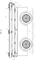
Figures 2 and3 are a view in side elevation and a view in front elevation of the assembly ofFigure 1 ; -
Figures 4 and 5 are top plan views of the installation field that show the movement of the carriage in the final step of the installation operation; -
Figure 6 is a schematic side view of the lifting device in the raised condition; -
Figure 7 is a schematic side view of the lifting device in the lowered condition; -
Figure 8 is a further perspective view of the lifting device; -
Figure 9 is a front view of the lifting device, which shows the possibility of oscillation about a longitudinal central axis of an auxiliary supporting structure mounted on the lifting device; -
Figure 10 is a perspective view that illustrates the carriage by itself, with the lifting device in the lowered condition; -
Figure 11 is a front view of the carriage ofFigure 10 , with the lifting device in the lowered condition; -
Figure 12 is a side view of the carriage ofFigure 10 , with the lifting device in the lowered condition; -
Figures 13 to 15 are a front view, a perspective view, and a detail of one of the clamping devices carried by the lifting device; and -
Figures 16 and 17 are a front view and perspective view, respectively, of an accessory tool that is associated to the longitudinal beam of the supporting frame. - In
Figures 1 to 3 , thereference number 1 designates as a whole an array of solar converters, in the specific example photovoltaic solar panels P. The invention may be applied also to arrays of solar converters of a different type, for example arrays of solar mirrors. - In the example illustrated, the
array 1 of photovoltaic solar panels P has a general planar configuration, with a supportingframe 2 on which the panels P are fixed. In the example, theframe 2 comprises alongitudinal beam 3 and a plurality ofcross members 4. Once again in the case of the example illustrated, thearray 1 comprises two rows set alongside one another of panels P. Each panel is fixed to thelongitudinal beam 3 and to twocross members 4. Once again in the case of the example illustrated, only the two panels P at the right-hand end of the array (as viewed inFigure 1 ) each have a first side fixed to thebeam 3, a second side fixed to across member 4, and a third side, opposite to the second side, projecting in cantilever fashion from thecross member 3. - The
frame 2 and the panels P are assembled together to form thearray 1 in an assembly station (not illustrated) close to the installation field (preferably with the method illustrated in the priorpatent application IT 10 2020 000010507 - Once assembled, the
array 1 of panels P is transported as far as the installation site by means of acarriage 5, which supports theframe 2 for supporting thearray 1 by means of alifting device 6, via which thearray 1 of panels P can be displaced vertically. As may be seen inFigure 1 , thelifting device 6 maintains the general plane of thearray 1 with a substantially horizontal orientation, but is also able, as will be described in what follows, to tilt thearray 1 forwards or backwards in the longitudinal direction of thecarriage 5, and also laterally on one side or on the other in such a way as to lay thearray 1 in the installation field with the orientation most suited in relation to the local incline of the terrain. - The
carriage 5 may be built according to any known technique, for example according to the technology commonly used for vehicles of the AGV or AMR type. - In one example, the
carriage 5 has a load-bearing structure 50 mounted on wheels R that are all orientable about vertical axes in such a way that the carriage can both translate in a direction parallel to its longitudinal direction, forwards or backwards, and veer with respect to the longitudinal direction, as well as translate in a transverse direction with respect to the aforesaid longitudinal direction, by means of rotation through 90° of the wheels about the respective vertical axes of orientation. The load-bearing structure 50 carries electric motors for orientation of the wheels about the respective vertical axes of oscillation and electric motors for traction on the wheels. - All the aforesaid details of construction are not illustrated herein in so far as they can be implemented in any known way. In the drawings, the wheels R are represented as conventional wheels merely for convenience of representation.
- Moreover illustrated schematically in
Figure 2 are an electronic control unit E and an electric power-supply battery B, which are prearranged on the load-bearing structure 50 of thecarriage 5. The electronic control unit E is configured and programmed both for controlling the electric motors on board thecarriage 5, in order to displace the carriage according to a pre-set path, and for controlling the electric actuators (described in what follows), which control thelifting device 6. The electronic control unit E on board thecarriage 5 is in communication, preferably in wireless mode, with a driving device A (seeFigure 1 ), which may, for example, be controlled by an operator O who is walking close to thecarriage 5. Of course, this mode of use is here represented merely by way of example. The driving device A could also be controlled by an operator from a control tower, or, once again by way of example, thecarriage 5 could be displaced in the installation field using a tractor. - With reference to
Figure 2 , thelifting device 6 includes afirst lifter 6A and asecond lifter 6B, which are set at a distance apart from one another in the longitudinal direction of thecarriage 5. In the example, both of thelifters - The use of two
lifters lifters array 1 of panels P. In other words, the general plane of thearray 1 can be longitudinally tilted forwards or backwards. This characteristic is useful for orienting the general plane of thearray 1 in the most appropriate way, taking into account the configuration of the terrain on which thearray 1 of panels P is to be positioned. -
Figures 4 and 5 are top plan views that show the final steps of positioning of anarray 1 of panels P in the installation field. - In the installation field, a number of rows of supporting posts 7 are prearranged, set longitudinally at a distance apart from one another.
Figures 4 and 5 show a row of supporting posts 7 with an array 1' of panels P previously positioned, with theirlongitudinal supporting beam 3 connected to the supporting posts 7. -
Figure 4 shows a step in which thecarriage 5 is moving in a direction transverse with respect to its longitudinal direction, thanks to an orientation of its wheels R rotated through 90° with respect to the normal orientation for advance in a longitudinal direction.Figure 5 shows the final position reached by thecarriage 5, where thecarriage 5 enters the space comprised between two posts 7 adjacent to one another. The mutual distancing of the posts 7 in the installation field and the length of thecarriage 5 in its longitudinal direction are chosen in such a way as to enable thecarriage 5 to insert itself in the space between two successive posts 7. - During the movement of approach illustrated in
Figures 4 and 5 , thelifting device 6 of thecarriage 5, including thelifters Figure 2 , to guarantee that the plane of thearray 1 of panels P is located on the supporting posts 7. - Once the position illustrated in
Figure 5 is reached, where the supportingbeam 3 of thearray 1 of panels P is aligned, in top plan view, with the row of supporting posts 7, the operator drives lowering of thelifters beam 3 of thearray 1 is laid on the supporting posts 7 located underneath. - According to a technique in itself known, the supporting
beam 3 of each array of panels is received within receptacles defined by coupling members carried by the top ends of the supporting posts 7. These coupling members have a first portion that receives the supportingbeam 3 and that is connected in an articulated way to a second portion anchored to the top of the respective supporting post in such a way as to allow oscillation of the supportingbeam 3 about an axis parallel to its longitudinal direction. Once again according to the known art, the movement of oscillation maybe controlled by actuator devices of any type for providing a device for tracking the apparent motion of the Sun during the day. In this way, eacharray 1 of panels P oscillates progressively about an axis parallel to itslongitudinal supporting beam 3 when the system of solar converters is in use. - The aforesaid details regarding the solar-tracking device are not described herein given that, as already mentioned, they can be obtained in any known way and, taken in themselves, do not fall within the scope of the present invention.
- In the preferred embodiment illustrated herein, the
lifters lifting device 6 have the structure more clearly visible inFigures 6, 7 , and8 . - With initial reference to
Figure 6 , thelifting device 6 comprises abase structure 8, which is secured to the load-bearing structure 50 of thecarriage 5, and an upper structure 9 (schematically illustrated inFigures 6 and 7 ), which can be displaced vertically with respect to thebase structure 8 by means of thelifters - In the example illustrated, the
lifters Figure 8 , thelifters main arms lower structure 8 about fixedtransverse axes longitudinal guides 90 of theupper structure 9. Thelifters Figure 8 ), having top ends connected in an articulated way to thearms longitudinal guides 80 of thebase structure 8. Associated to the twolifters cylinder actuators Figure 8 ) operatively set between thebase structure 8 and thearms - Activation of the
actuators upper structure 9 with respect to thelower structure 8. - As already mentioned above, the electronic control unit is prearranged to enable differentiated driving of the
actuators arms upper structure 9 can be longitudinally inclined forwards or backwards (i.e., towards the left or towards the right as viewed inFigure 6 ) to impart on thearray 1 of panels P carried by the lifting device 6 a corresponding inclination. In this way, it is possible to adapt the array ofpanels 1 to being laid on supporting posts that are set at different heights, on account of an incline of the terrain in the longitudinal direction of the row of supporting posts. - With reference once again to the embodiment shown in
Figure 8 , theupper structure 9 is in the form of a quadrangular frame, with two longitudinal beams L, the ends of which are connected together by cross members T. This structure is able to perform a limited longitudinal movement with respect to theguides 90 within which the top ends of thearms lifters cylinder actuators 91. Thanks to this characteristic, once the liftingdevice 6 has laid thearray 1 of panels P on the supporting posts 7, and the supportingbeam 3 of thearray 1 have been inserted in the receptacles provided at the top of the posts, theactuators 91 can be driven to impart on the entire array 1 a slight longitudinal movement with respect to thecarriage 5 on which it is carried, which is necessary for coupling one end of the longitudinal supportingbeam 3 with a corresponding end of the supporting beam of theadjacent array 1 of panels P that has been previously laid in the installation field. - Once again with reference to
Figures 8 and9 , the two end cross members T of theupper structure 9 carry twolongitudinal pins 10, which have the function of supporting in an oscillating way, about a longitudinalcentral axis 11, an auxiliary supporting structure 12 (Figure 9 ) that is to support thearray 1 of panels P directly. A rotation of theauxiliary supporting structure 12 about the longitudinalcentral axis 11 can be controlled by means of an actuator 13 (Figure 8 ) carried by theupper structure 9. -
Figure 10 shows a perspective view of the carriage 5 (for convenience of illustration, the wheels R have been illustrated as conventional wheels), with thelifting device 6 illustrated in the lowered condition.Figure 10 , shows, partially sectioned, theauxiliary supporting structure 12. This structure includes two longitudinal beams L1 having the ends connected by two cross members T1. Each cross member T1 (one of which is represented partially sectioned inFigure 10 ) has acentral portion 14 arched downwards with respect to the ends of the cross member T1 in such a way as not to interfere with the area that is to receive thelongitudinal beam 3 for supporting thearray 1 of panels P. - The
longitudinal beam 3 of the frame for supporting thearray 1 of panels is to be received in the receptacles of a plurality of clamping devices 15 (in the example illustrated, threeclamping devices 15 are provided) carried bycross members 150 having their ends connected to the two longitudinal beams L1. -
Figures 13-15 show aclamping device 15 at an enlarged scale. The structure of thecross member 150 defines areceptacle 151 for receiving the supportingbeam 3 of thearray 1 of panels P. The receptacle has a bottom wall and two side walls defined by twoplates 153. Once thelongitudinal beam 3 is received within thereceptacle 151, it can be blocked in this position by means of two blockingelements 152 that can be displaced between an operative blocking position and an open released position (not illustrated). The movement of the two blockingelements 152 is controlled by means of respective actuators of any known type (not illustrated). - In the carriage according to the invention, the
clamping devices 15 carried by thelifting device 6 are used both when anarray 1 of panels P is being loaded onto thecarriage 5 in the workstation for assembly of the array of panels and during laying of the array of panels in the installation field. - During loading of the
array 1 of panels onto the carriage 5 (not illustrated in the annexed drawings) the carriage sets itself underneath the assembled array, and the lifting device is driven to raise theupper structure 9 and, along with it, theauxiliary supporting structure 12, maintaining theclamping devices 15 in the open condition. In this way, thelongitudinal beam 3 of the supporting frame of the array of panels is received within the receptacles of theclamping devices 15, following upon raising of theupper structure 9 by the lifting device. Once thebeam 3 for supporting the array of panels has been received within theseats 151 of the clamping devices, the latter are activated for blocking thebeam 3 on thestructure 12. The lifting device can thus be lowered, and the carriage can be driven to bring the array of panels onto the installation site. - Once the installation site is reached, the step already described above with reference to
Figures 4 and 5 is activated in order to position thelongitudinal beam 3 of the supporting frame of the array of panels on the receptacles provided at the top ends of the supporting posts 7 in the installation field. - The possibility of orienting the
auxiliary supporting structure 12 about thelongitudinal axis 11 enables, in this step, inclination, if so required, of the general plane of the array of panels laterally on one side or on the other, imparting thereon a rotation of roll (Figure 9 ) so as to take into account a possible incline of the terrain in the direction transverse to the longitudinal direction of the row of supporting posts 7. - Once the
longitudinal beam 3 of the supporting frame of the array of panels has been received in the receptacles provided at the top ends of the supporting posts, theactuators 91 are activated (Figure 8 ) to impart on the entire array of panels the slight longitudinal movement that is necessary for coupling one end of thelongitudinal beam 3 of the array to the corresponding end of the longitudinal beam of the supporting frame of the adjacent array of panels, previously laid in the installation field. Once the connection between the longitudinal beams has been made (for example, with the intervention of operators) thelongitudinal beam 3 can then be blocked in the receptacles of the connection devices provided at the top ends of the supporting posts 7. - According to a preferred characteristic, the
clamping devices 13 enable positioning of the blockingelements 152 also in an intermediate position between the open position and the gripping position, where thebeam 3 is loosely blocked. In this configuration, thebeam 3 is prevented from coming out of thereceptacle 151 but has, however, a limited play within the receptacle that allows minor movements of adjustment during the operations of connection of thebeam 3 to the connection devices provided at the top ends of the supporting posts 7. - Once the operations of connection are completed (for example, by carrying out manual operations), the
clamping devices 15 can be completely opened, and thelifting device 6 can be lowered to release the carriage completely from thearray 1 of panels laid in the installation field. -
Figures 16 and 17 illustrate an accessory tool that is associated to thelongitudinal beam 3 of the supporting frame of thearray 1 of panels in order to support the last row of panels of the array during transport. - With reference to
Figure 1 , the two end panels of the array (the right-hand end in the figure) project in cantilever fashion with respect to the end of the longitudinal supportingbeam 3. Consequently, unlike the other panels, they are not supported on opposite sides by twocross members 4. To support in a reliable way these panels during transport, mounted on thecross member 3 is the accessory member illustrated inFigures 16 and 17 and designated by thereference 16. This member is constituted by a transverse bar 163 (in the example with circular section) provided at the centre with aclamp 160 to be gripped on one end of thecross member 3. In the example illustrated, theclamp 160 comprises twoclamping devices 161 of the manually driven toggle type, but of course any clamping device may be used for this purpose. Thebar 16 functions as further support for the two end panels P of the array and is also provided at its ends with two further manually driven clampingdevices 162, which are, for example, also of the toggle type, for blocking the panels P on thebar 16. - The configuration of the supporting frame of the array of solar converters could also be different from the one illustrated herein by way of example. Furthermore, in the present description and in the ensuing claims, the term "longitudinal beam" is to be understood in a general sense, as comprising also the case of one or more beam elements that do not extend throughout the length of the array of solar converters.
- Likewise, the expression "substantially horizontal orientation" of the general plane of the array of solar converters is to be understood in a broad sense as defining an orientation in any case considerably different from a vertical orientation. As has been seen previously, the general plane of the array may be inclined, both longitudinally and laterally, with respect to the horizontal arrangement, according to the profile of the terrain in the area of installation. For the same reason, the movement of the lifting device may occur in a direction different from a vertical direction.
- In the example illustrated here, the supporting posts 7 prearranged in the installation field are sufficiently tall to receive thereon the
array 1 when thelifters carriage 5 are lowered. In the case where the supporting posts 7 are too low to enable this operating mode, it is possible to envisage that thelifters array 1 on taller auxiliary posts, for example having a telescopic configuration, previously arranged in the installation field. Once the carriage has been released from thearray 1, after the latter has been laid on the aforesaid auxiliary posts, these are shortened to lay thearray 1 on the shorter main posts. - Naturally, without prejudice to the principle of the invention, the details of construction and the embodiments may vary widely with respect to what has been described and illustrated herein purely by way of example, without thereby departing from the scope of the present invention, as defined in the claims.
Claims (18)
- A method for outdoor installation of an array (1) of solar converters including a supporting frame (2) and a plurality of solar converters (P) mounted on the supporting frame (2),wherein said supporting frame (2) is to be laid on a supporting structure comprising an aligned series of supporting posts (7) arranged in the installation field,wherein a vehicle (5) is provided for transporting the array (1) of solar converters (P) and for laying said array (1) of solar converters (P) on said supporting structure (7),wherein the vehicle (5) is provided with a lifting device (6) for displacing the array (1) of solar converters (P) between a raised position and a lowered position, maintaining a general plane of the array with a substantially horizontal orientation, until the array (1) of solar converters (P) is laid on said supporting structure (7),said method being characterized in that:- said supporting frame (2) of the array (1) of solar converters includes a longitudinal beam (3) that is to be laid on said aligned series of supporting posts (7),said vehicle is a carriage (5) that comprises:- a load-bearing structure (50) mounted on wheels (R); and- a main upper structure (9) of the carriage (5), prearranged for receiving thereon the array (1) of solar converters,- said lifting device (6) being set between said load-bearing structure (50) and said main upper structure (9) of the carriage, loaded on which is the array (1) of solar converters,associated to the carriage (5) is an electronic control unit (E) for controlling the movement of the carriage (5) and for driving the lifting device (6), andsaid electronic control unit (E) is configured for executing the following steps:- bringing the carriage (5) up adjacent to a row of supporting posts (7) in the installation field;- lifting the array (1) of solar converters (P) above said supporting posts (7);- displacing the carriage (5) within a space comprised between two successive posts (7) of the row; and- lowering the array (1) of solar converters (P) until the longitudinal beam (3) of the supporting frame (2) of the array (1) of solar converters (P) is laid on the supporting posts (7) of the row.
- The method according to claim 1, characterized in that said lifting device (6) includes a first lifter (6A) and a second lifter (6B) arranged on the carriage (5) in positions spaced apart from one another in a longitudinal direction of the carriage (5); and
wherein said electronic control unit (E) is configured in such a way as to be able to control the first and second lifters (6A and 6B) if necessary in a differentiated way, in order to impart on the general plane of the array (1) of solar converters an orientation longitudinally inclined forwards or backwards. - The method according to claim 2, characterizedin that said first lifter (6A) and said second lifter (6B) are both set between said load-bearing structure (50) of the carriage (5) and said main upper structure (9),in that associated to said main upper structure (9) is an auxiliary supporting structure (12) onto which the array (1) of solar converters (P) is loaded,said auxiliary supporting structure (12) being mounted so that it can oscillate about a longitudinal central axis (11) on said main upper structure (9), andin that an actuator (13) is provided for controlling rotation of the auxiliary supporting structure (12) about said longitudinal central axis (11) in such a way as to impart on the general plane of the array (1) of solar converters (P) a laterally inclined orientation.
- The method according to claim 3, characterized in that the auxiliary supporting structure (12) carries a plurality of clamping devices (15) set longitudinally at a distance apart from one another, to receive and block the longitudinal beam (3) of the supporting frame (2) of the array (1) of solar converters (P).
- The method according to claim 4, characterized in that each clamping device (15) comprises a receptacle (151) received in which is the longitudinal supporting beam (3) and blocking elements (152) that can be displaced between a closed blocking position and an open release position.
- The method according to claim 5, characterized in that said blocking elements (152) have an intermediate operating position, where the longitudinal supporting beam (3) is prevented from coming out of the receptacle (151) of the clamping device (15) while maintaining a play within said receptacle (151).
- The method according to claim 3, characterized in that the upper structure (9) includes a first portion (90) operatively connected to the lifting device (6) and a second portion (9), mounted on which is said auxiliary supporting structure (12) and which is mounted so that it has a limited longitudinal movement with respect to said first portion, it being possible for said movement to be driven by a corresponding actuator (91).
- The method according to claim 1, characterized in that:- said load-bearing structure (50) is mounted on wheels (R) that are orientable about vertical axes in such a way as to enable the carriage to move forwards or backwards in a direction parallel to a longitudinal direction of the carriage, to veer with respect to said longitudinal direction, and/or to translate in a direction orthogonal to said longitudinal direction; and- the carriage comprises at least one first electric motor carried by the load-bearing structure for controlling traction of one or more of said wheels (R) and a further electric motor associated to each of said wheels for controlling the orientation of each wheel (R) about the respective vertical axis of oscillation.
- The method according to claim 8, characterized in that associated to the electronic control unit (E) is a driving device (A) for controlling both said electric motors for the movement of the carriage (5) and electric actuators of the lifting device (6).
- The method according to any one of the preceding claims, characterized in that, during transport on the carriage (5), associated to one end of the longitudinal beam (3) of the supporting frame (2) is an accessory tool (16) comprising a vice (160) that can be blocked on the beam (3) and carries a transverse bar (163) that supports a last row of solar converters (P) that project in cantilever fashion beyond said end of the beam (3).
- A carriage for transport and outdoor installation of an array (1) of solar converters (P), comprising:- a lifting device (6) for displacing vertically an array (1) of solar converters (P) loaded thereon between a position of maximum raising and a position of maximum lowering,said carriage being characterized in that it comprises:- a load-bearing structure (50) mounted on wheels (R); and- a main upper structure (9) of the carriage (5), arranged for receiving thereon the array (1) of solar converters,- said lifting device (6) being set between said load-bearing structure (50) and said main upper structure (9) of the carriage, on which the array (1) of solar converters is loaded; and- an electronic control unit for controlling the movement of the carriage and of the lifting device (6),wherein said lifting device includes a first lifter (6A) and a second lifter (6B) arranged on the carriage in positions spaced apart from one another in a longitudinal direction of the carriage,said first and second lifters (6A and 6B) both being set between said base structure (8) secured to the load-bearing structure (50) of the carriage (5) and said main upper structure (9) that is to carry, directly or indirectly, the array (1) of solar converters,in such a way that said first and second lifters (6A and 6B) can be driven in a differentiated way to impart on the general plane of the array (1) of solar converters (P) an orientation longitudinally inclined forwards or backwards.
- The carriage according to claim 11, characterized in that:- associated to said main upper structure (9) is an auxiliary supporting structure (12) loaded onto which is the array (1) of solar converters (P),said auxiliary supporting structure (12) is mounted so that it can oscillate about a longitudinal central axis (11) on said main upper structure (9), andsaid carriage (5) further comprises an actuator (13) for controlling rotation of the auxiliary supporting structure (12) about said longitudinal central axis (11) in such a way as to impart on the general plane of the array (1) of solar converters (P) a laterally inclined orientation.
- The carriage according to claim 12, characterized in that the auxiliary supporting structure (12) carries a plurality of clamping devices (15), set longitudinally at a distance apart from one another, to receive and block the longitudinal beam (3) of the supporting frame (2) of the array (1) of solar converters (P).
- The carriage according to claim 13, characterized in that each clamping device (15) comprises a receptacle (151), received in which is the longitudinal supporting beam (3), and blocking elements (152) that can be displaced between a closed blocking position and an open release position.
- The carriage according to claim 14, characterized in that said blocking elements (152) have an intermediate operating position where the longitudinal supporting beam (3) is prevented from coming out of the receptacle (151) of the clamping device (15) while maintaining a certain play within said receptacle (151).
- The carriage according to claim 12, characterized in that the upper structure (9) includes a first upper-structure portion (90) operatively connected to the lifting device (6) and a second portion (9), mounted on which is said auxiliary supporting structure (12) and which is mounted so that it has a limited longitudinal movement with respect to said first portion, it being possible for said movement to be driven by means of a corresponding actuator (91).
- The carriage according to claim 11, characterized in that:- said load-bearing structure (50) is mounted on wheels (R) that are orientable about vertical axes in such a way as to enable the carriage to move forwards or backwards in a direction parallel to a longitudinal direction of the carriage, to veer with respect to said longitudinal direction, and/or to translate in a direction orthogonal to said longitudinal direction,- the carriage comprises at least one first electric motor carried by the load-bearing structure for controlling traction of one or more of said wheels (R) and a further electric motor associated to each of said wheels for controlling the orientation of each wheel (R) about the respective vertical axis of oscillation.
- The carriage according to claim 17, characterized in that associated to the electronic control unit (E) is a driving device (A) for controlling said electric motors of the carriage (5) and electric actuators of the lifting device (6).
Applications Claiming Priority (2)
| Application Number | Priority Date | Filing Date | Title |
|---|---|---|---|
| IT202000028190 | 2020-11-24 | ||
| PCT/IB2021/060809 WO2022112921A1 (en) | 2020-11-24 | 2021-11-22 | Method for outdoor installation of an array of solar converters, and carriage used in the method |
Publications (2)
| Publication Number | Publication Date |
|---|---|
| EP4251471A1 EP4251471A1 (en) | 2023-10-04 |
| EP4251471B1 true EP4251471B1 (en) | 2025-06-25 |
Family
ID=74669250
Family Applications (1)
| Application Number | Title | Priority Date | Filing Date |
|---|---|---|---|
| EP21814915.1A Active EP4251471B1 (en) | 2020-11-24 | 2021-11-22 | Method for outdoor installation of an array of solar converters, and carriage used in the method |
Country Status (10)
| Country | Link |
|---|---|
| US (1) | US20240001836A1 (en) |
| EP (1) | EP4251471B1 (en) |
| CN (1) | CN116583433B (en) |
| AU (1) | AU2021386577A1 (en) |
| CL (1) | CL2023001409A1 (en) |
| ES (1) | ES3039313T3 (en) |
| MX (1) | MX2023005783A (en) |
| PT (1) | PT4251471T (en) |
| WO (1) | WO2022112921A1 (en) |
| ZA (1) | ZA202305260B (en) |
Families Citing this family (10)
| Publication number | Priority date | Publication date | Assignee | Title |
|---|---|---|---|---|
| EP4122097A4 (en) | 2020-03-20 | 2024-05-29 | Rosendin Electric, Inc. | A robotic arm cooperating with an off-road capable base vehicle |
| US11999284B2 (en) | 2021-09-01 | 2024-06-04 | Terabase Energy, Inc. | Solar table mobile transport |
| US11938576B1 (en) | 2022-12-20 | 2024-03-26 | Terabase Energy, Inc. | Systems and methods for threading a torque tube through U-bolt and module rail devices |
| US20240235470A1 (en) | 2023-01-09 | 2024-07-11 | Sarcos Corp. | Auto-Engaging Electrical Connections for Solar Panels |
| US12466066B2 (en) | 2023-05-04 | 2025-11-11 | Sarcos Corp. | Solar panel dispensing device with vertical solar panel hopper loading and dispensing |
| US20240424971A1 (en) * | 2023-06-26 | 2024-12-26 | Terabase Energy, Inc. | Solar table mobile transport with sideshift and wings |
| US20250128930A1 (en) * | 2023-10-18 | 2025-04-24 | Terabase Energy, Inc. | Solar table mobile transport with collapsible manipulators |
| US12542513B2 (en) | 2024-01-08 | 2026-02-03 | Sarcos Corp. | Torque tube clamps for automated solar panel installation |
| US20250223118A1 (en) * | 2024-01-08 | 2025-07-10 | Sarcos Corp. | Solar Panel Installation Vehicles as Part of a Solar Panel Installation System for A Solar Tracking System |
| US12570001B2 (en) | 2024-01-08 | 2026-03-10 | Sarcos Corp. | Support clamp installation vehicles as part of a solar panel installation system for a solar tracking system |
Family Cites Families (7)
| Publication number | Priority date | Publication date | Assignee | Title |
|---|---|---|---|---|
| US11063553B2 (en) * | 2008-11-17 | 2021-07-13 | Kbfx Llc | Solar carports, solar-tracking carports, and methods |
| DE102009024740A1 (en) * | 2009-06-12 | 2010-12-16 | Adensis Gmbh | Charging vehicle for an assembly machine for photovoltaic modules |
| DE102010038054A1 (en) * | 2010-09-08 | 2012-03-08 | Reis Group Holding Gmbh & Co. Kg | Method for handling solar cell modules arranged in rows on substrate of solar system in vehicle, involves forming aperture of specific dimension at interior of frame to monitor position of solar cell modules during handling of modules |
| WO2014108196A1 (en) * | 2013-01-10 | 2014-07-17 | Florian Schubert | Method and system for mounting solar panels |
| US9324893B1 (en) * | 2013-12-10 | 2016-04-26 | Solaero Technologies Corp. | Portable solar power system and method for the same |
| DE112015002021T5 (en) * | 2014-04-28 | 2017-02-23 | Clean Energy Factory Co. , Ltd. | Method of constructing a solar power plant |
| PT3711157T (en) * | 2017-11-14 | 2022-11-21 | Comau Spa | A method and system for installing photovoltaic solar panels in an outdoor area |
-
2021
- 2021-11-22 EP EP21814915.1A patent/EP4251471B1/en active Active
- 2021-11-22 MX MX2023005783A patent/MX2023005783A/en unknown
- 2021-11-22 PT PT218149151T patent/PT4251471T/en unknown
- 2021-11-22 ES ES21814915T patent/ES3039313T3/en active Active
- 2021-11-22 AU AU2021386577A patent/AU2021386577A1/en active Pending
- 2021-11-22 WO PCT/IB2021/060809 patent/WO2022112921A1/en not_active Ceased
- 2021-11-22 US US18/037,850 patent/US20240001836A1/en active Pending
- 2021-11-22 CN CN202180078944.9A patent/CN116583433B/en active Active
-
2023
- 2023-05-12 ZA ZA2023/05260A patent/ZA202305260B/en unknown
- 2023-05-16 CL CL2023001409A patent/CL2023001409A1/en unknown
Also Published As
| Publication number | Publication date |
|---|---|
| CL2023001409A1 (en) | 2023-11-17 |
| CN116583433B (en) | 2026-04-03 |
| AU2021386577A9 (en) | 2025-03-13 |
| EP4251471A1 (en) | 2023-10-04 |
| WO2022112921A1 (en) | 2022-06-02 |
| AU2021386577A1 (en) | 2023-06-08 |
| ZA202305260B (en) | 2024-01-31 |
| ES3039313T3 (en) | 2025-10-21 |
| MX2023005783A (en) | 2023-10-03 |
| CN116583433A (en) | 2023-08-11 |
| US20240001836A1 (en) | 2024-01-04 |
| PT4251471T (en) | 2025-08-13 |
Similar Documents
| Publication | Publication Date | Title |
|---|---|---|
| EP4251471B1 (en) | Method for outdoor installation of an array of solar converters, and carriage used in the method | |
| US20240028027A1 (en) | Solar panel installation system | |
| US11964860B2 (en) | Solar panel direct-motion installation apparatus | |
| US12060042B2 (en) | Service vehicle with drone bases | |
| US20230163720A1 (en) | Method And System For Assembling And Installing Arrays Of Photovoltaic Solar Panels In An Outdoor Field | |
| US20110099788A1 (en) | Final assembly machine and method of use | |
| KR20220092981A (en) | Rescue systems and methods for recovering faulty carriers from rail systems | |
| NO344308B1 (en) | Storage system comprising a charging station assembly and method of replacing the power source of a remotely operated vehicle | |
| KR20100114615A (en) | Moving apparatus of welding robot for climbing over the longitudinal | |
| CN116871785B (en) | Fabric laying unit, longitudinal reinforcement laying equipment and fabric laying method | |
| CN114919998B (en) | Integrated equipment feeding equipment and feeding method | |
| JP7519135B1 (en) | Transporting and installing blocks | |
| EP4536543A1 (en) | Mobile assembly line and associated method, particularly for the assembly of vehicles | |
| JPS62218305A (en) | Lifting carriage for automobile body | |
| CN221219699U (en) | Workstation of construction robot | |
| KR100892168B1 (en) | Cdd module transfer crane | |
| JP2764481B2 (en) | Construction machine for precast concrete members | |
| CN114086438A (en) | Spatial linear fine adjustment equipment for track beam in tunnel and intelligent control method thereof | |
| CN117802893A (en) | A control system, a support system of the control system, and a control method of the support system | |
| KR200225697Y1 (en) | Welding system for steel box | |
| CN120625601A (en) | Highway guardrail pile erection system and method | |
| JPH04350261A (en) | How to build precast concrete members |
Legal Events
| Date | Code | Title | Description |
|---|---|---|---|
| STAA | Information on the status of an ep patent application or granted ep patent |
Free format text: STATUS: UNKNOWN |
|
| STAA | Information on the status of an ep patent application or granted ep patent |
Free format text: STATUS: THE INTERNATIONAL PUBLICATION HAS BEEN MADE |
|
| PUAI | Public reference made under article 153(3) epc to a published international application that has entered the european phase |
Free format text: ORIGINAL CODE: 0009012 |
|
| STAA | Information on the status of an ep patent application or granted ep patent |
Free format text: STATUS: REQUEST FOR EXAMINATION WAS MADE |
|
| 17P | Request for examination filed |
Effective date: 20230516 |
|
| AK | Designated contracting states |
Kind code of ref document: A1 Designated state(s): AL AT BE BG CH CY CZ DE DK EE ES FI FR GB GR HR HU IE IS IT LI LT LU LV MC MK MT NL NO PL PT RO RS SE SI SK SM TR |
|
| DAV | Request for validation of the european patent (deleted) | ||
| DAX | Request for extension of the european patent (deleted) | ||
| GRAP | Despatch of communication of intention to grant a patent |
Free format text: ORIGINAL CODE: EPIDOSNIGR1 |
|
| STAA | Information on the status of an ep patent application or granted ep patent |
Free format text: STATUS: GRANT OF PATENT IS INTENDED |
|
| RIC1 | Information provided on ipc code assigned before grant |
Ipc: F24S 25/12 20180101ALI20250205BHEP Ipc: B60P 3/40 20060101ALI20250205BHEP Ipc: H02S 20/00 20140101ALI20250205BHEP Ipc: B60P 3/00 20060101ALI20250205BHEP Ipc: B60P 1/00 20060101AFI20250205BHEP |
|
| INTG | Intention to grant announced |
Effective date: 20250226 |
|
| GRAS | Grant fee paid |
Free format text: ORIGINAL CODE: EPIDOSNIGR3 |
|
| GRAA | (expected) grant |
Free format text: ORIGINAL CODE: 0009210 |
|
| STAA | Information on the status of an ep patent application or granted ep patent |
Free format text: STATUS: THE PATENT HAS BEEN GRANTED |
|
| AK | Designated contracting states |
Kind code of ref document: B1 Designated state(s): AL AT BE BG CH CY CZ DE DK EE ES FI FR GB GR HR HU IE IS IT LI LT LU LV MC MK MT NL NO PL PT RO RS SE SI SK SM TR |
|
| REG | Reference to a national code |
Ref country code: GB Ref legal event code: FG4D |
|
| REG | Reference to a national code |
Ref country code: CH Ref legal event code: EP |
|
| REG | Reference to a national code |
Ref country code: DE Ref legal event code: R096 Ref document number: 602021033003 Country of ref document: DE |
|
| REG | Reference to a national code |
Ref country code: CH Ref legal event code: EP |
|
| REG | Reference to a national code |
Ref country code: IE Ref legal event code: FG4D |
|
| REG | Reference to a national code |
Ref country code: PT Ref legal event code: SC4A Ref document number: 4251471 Country of ref document: PT Date of ref document: 20250813 Kind code of ref document: T Free format text: AVAILABILITY OF NATIONAL TRANSLATION Effective date: 20250807 |
|
| PG25 | Lapsed in a contracting state [announced via postgrant information from national office to epo] |
Ref country code: FI Free format text: LAPSE BECAUSE OF FAILURE TO SUBMIT A TRANSLATION OF THE DESCRIPTION OR TO PAY THE FEE WITHIN THE PRESCRIBED TIME-LIMIT Effective date: 20250625 |
|
| REG | Reference to a national code |
Ref country code: LT Ref legal event code: MG9D |
|
| PG25 | Lapsed in a contracting state [announced via postgrant information from national office to epo] |
Ref country code: GR Free format text: LAPSE BECAUSE OF FAILURE TO SUBMIT A TRANSLATION OF THE DESCRIPTION OR TO PAY THE FEE WITHIN THE PRESCRIBED TIME-LIMIT Effective date: 20250926 Ref country code: NO Free format text: LAPSE BECAUSE OF FAILURE TO SUBMIT A TRANSLATION OF THE DESCRIPTION OR TO PAY THE FEE WITHIN THE PRESCRIBED TIME-LIMIT Effective date: 20250925 |
|
| PG25 | Lapsed in a contracting state [announced via postgrant information from national office to epo] |
Ref country code: BG Free format text: LAPSE BECAUSE OF FAILURE TO SUBMIT A TRANSLATION OF THE DESCRIPTION OR TO PAY THE FEE WITHIN THE PRESCRIBED TIME-LIMIT Effective date: 20250625 |
|
| PG25 | Lapsed in a contracting state [announced via postgrant information from national office to epo] |
Ref country code: HR Free format text: LAPSE BECAUSE OF FAILURE TO SUBMIT A TRANSLATION OF THE DESCRIPTION OR TO PAY THE FEE WITHIN THE PRESCRIBED TIME-LIMIT Effective date: 20250625 |
|
| REG | Reference to a national code |
Ref country code: ES Ref legal event code: FG2A Ref document number: 3039313 Country of ref document: ES Kind code of ref document: T3 Effective date: 20251021 |
|
| PG25 | Lapsed in a contracting state [announced via postgrant information from national office to epo] |
Ref country code: RS Free format text: LAPSE BECAUSE OF FAILURE TO SUBMIT A TRANSLATION OF THE DESCRIPTION OR TO PAY THE FEE WITHIN THE PRESCRIBED TIME-LIMIT Effective date: 20250925 |
|
| PG25 | Lapsed in a contracting state [announced via postgrant information from national office to epo] |
Ref country code: LV Free format text: LAPSE BECAUSE OF FAILURE TO SUBMIT A TRANSLATION OF THE DESCRIPTION OR TO PAY THE FEE WITHIN THE PRESCRIBED TIME-LIMIT Effective date: 20250625 |
|
| REG | Reference to a national code |
Ref country code: NL Ref legal event code: MP Effective date: 20250625 |
|
| PG25 | Lapsed in a contracting state [announced via postgrant information from national office to epo] |
Ref country code: NL Free format text: LAPSE BECAUSE OF FAILURE TO SUBMIT A TRANSLATION OF THE DESCRIPTION OR TO PAY THE FEE WITHIN THE PRESCRIBED TIME-LIMIT Effective date: 20250625 |
|
| PGFP | Annual fee paid to national office [announced via postgrant information from national office to epo] |
Ref country code: PT Payment date: 20251103 Year of fee payment: 5 |
|
| REG | Reference to a national code |
Ref country code: AT Ref legal event code: MK05 Ref document number: 1806160 Country of ref document: AT Kind code of ref document: T Effective date: 20250625 |
|
| PG25 | Lapsed in a contracting state [announced via postgrant information from national office to epo] |
Ref country code: IS Free format text: LAPSE BECAUSE OF FAILURE TO SUBMIT A TRANSLATION OF THE DESCRIPTION OR TO PAY THE FEE WITHIN THE PRESCRIBED TIME-LIMIT Effective date: 20251025 |
|
| PGFP | Annual fee paid to national office [announced via postgrant information from national office to epo] |
Ref country code: DE Payment date: 20251126 Year of fee payment: 5 |
|
| PGFP | Annual fee paid to national office [announced via postgrant information from national office to epo] |
Ref country code: GB Payment date: 20251125 Year of fee payment: 5 |
|
| PG25 | Lapsed in a contracting state [announced via postgrant information from national office to epo] |
Ref country code: SM Free format text: LAPSE BECAUSE OF FAILURE TO SUBMIT A TRANSLATION OF THE DESCRIPTION OR TO PAY THE FEE WITHIN THE PRESCRIBED TIME-LIMIT Effective date: 20250625 Ref country code: AT Free format text: LAPSE BECAUSE OF FAILURE TO SUBMIT A TRANSLATION OF THE DESCRIPTION OR TO PAY THE FEE WITHIN THE PRESCRIBED TIME-LIMIT Effective date: 20250625 |
|
| PGFP | Annual fee paid to national office [announced via postgrant information from national office to epo] |
Ref country code: FR Payment date: 20251124 Year of fee payment: 5 |
|
| PGFP | Annual fee paid to national office [announced via postgrant information from national office to epo] |
Ref country code: TR Payment date: 20251104 Year of fee payment: 5 |
|
| PG25 | Lapsed in a contracting state [announced via postgrant information from national office to epo] |
Ref country code: CZ Free format text: LAPSE BECAUSE OF FAILURE TO SUBMIT A TRANSLATION OF THE DESCRIPTION OR TO PAY THE FEE WITHIN THE PRESCRIBED TIME-LIMIT Effective date: 20250625 |
|
| PG25 | Lapsed in a contracting state [announced via postgrant information from national office to epo] |
Ref country code: PL Free format text: LAPSE BECAUSE OF FAILURE TO SUBMIT A TRANSLATION OF THE DESCRIPTION OR TO PAY THE FEE WITHIN THE PRESCRIBED TIME-LIMIT Effective date: 20250625 |
|
| PG25 | Lapsed in a contracting state [announced via postgrant information from national office to epo] |
Ref country code: EE Free format text: LAPSE BECAUSE OF FAILURE TO SUBMIT A TRANSLATION OF THE DESCRIPTION OR TO PAY THE FEE WITHIN THE PRESCRIBED TIME-LIMIT Effective date: 20250625 |
|
| PG25 | Lapsed in a contracting state [announced via postgrant information from national office to epo] |
Ref country code: SK Free format text: LAPSE BECAUSE OF FAILURE TO SUBMIT A TRANSLATION OF THE DESCRIPTION OR TO PAY THE FEE WITHIN THE PRESCRIBED TIME-LIMIT Effective date: 20250625 |
|
| PGFP | Annual fee paid to national office [announced via postgrant information from national office to epo] |
Ref country code: ES Payment date: 20251209 Year of fee payment: 5 |
|
| PG25 | Lapsed in a contracting state [announced via postgrant information from national office to epo] |
Ref country code: RO Free format text: LAPSE BECAUSE OF FAILURE TO SUBMIT A TRANSLATION OF THE DESCRIPTION OR TO PAY THE FEE WITHIN THE PRESCRIBED TIME-LIMIT Effective date: 20250625 |
|
| PG25 | Lapsed in a contracting state [announced via postgrant information from national office to epo] |
Ref country code: DK Free format text: LAPSE BECAUSE OF FAILURE TO SUBMIT A TRANSLATION OF THE DESCRIPTION OR TO PAY THE FEE WITHIN THE PRESCRIBED TIME-LIMIT Effective date: 20250625 |
|
| PG25 | Lapsed in a contracting state [announced via postgrant information from national office to epo] |
Ref country code: IT Free format text: LAPSE BECAUSE OF FAILURE TO SUBMIT A TRANSLATION OF THE DESCRIPTION OR TO PAY THE FEE WITHIN THE PRESCRIBED TIME-LIMIT Effective date: 20250625 |
|
| PLBE | No opposition filed within time limit |
Free format text: ORIGINAL CODE: 0009261 |
|
| STAA | Information on the status of an ep patent application or granted ep patent |
Free format text: STATUS: NO OPPOSITION FILED WITHIN TIME LIMIT |