EP4250999B1 - Insole - Google Patents
Insole Download PDFInfo
- Publication number
- EP4250999B1 EP4250999B1 EP21823989.5A EP21823989A EP4250999B1 EP 4250999 B1 EP4250999 B1 EP 4250999B1 EP 21823989 A EP21823989 A EP 21823989A EP 4250999 B1 EP4250999 B1 EP 4250999B1
- Authority
- EP
- European Patent Office
- Prior art keywords
- pod
- insole
- foam
- lip
- liquid
- Prior art date
- Legal status (The legal status is an assumption and is not a legal conclusion. Google has not performed a legal analysis and makes no representation as to the accuracy of the status listed.)
- Active
Links
Images


Classifications
-
- A—HUMAN NECESSITIES
- A43—FOOTWEAR
- A43B—CHARACTERISTIC FEATURES OF FOOTWEAR; PARTS OF FOOTWEAR
- A43B17/00—Insoles for insertion, e.g. footbeds or inlays, for attachment to the shoe after the upper has been joined
- A43B17/02—Insoles for insertion, e.g. footbeds or inlays, for attachment to the shoe after the upper has been joined wedge-like or resilient
- A43B17/026—Insoles for insertion, e.g. footbeds or inlays, for attachment to the shoe after the upper has been joined wedge-like or resilient filled with a non-compressible fluid, e.g. gel, water
-
- A—HUMAN NECESSITIES
- A43—FOOTWEAR
- A43B—CHARACTERISTIC FEATURES OF FOOTWEAR; PARTS OF FOOTWEAR
- A43B13/00—Soles; Sole-and-heel integral units
- A43B13/14—Soles; Sole-and-heel integral units characterised by the constructive form
- A43B13/18—Resilient soles
- A43B13/189—Resilient soles filled with a non-compressible fluid, e.g. gel, water
-
- A—HUMAN NECESSITIES
- A43—FOOTWEAR
- A43B—CHARACTERISTIC FEATURES OF FOOTWEAR; PARTS OF FOOTWEAR
- A43B17/00—Insoles for insertion, e.g. footbeds or inlays, for attachment to the shoe after the upper has been joined
- A43B17/003—Insoles for insertion, e.g. footbeds or inlays, for attachment to the shoe after the upper has been joined characterised by the material
- A43B17/006—Insoles for insertion, e.g. footbeds or inlays, for attachment to the shoe after the upper has been joined characterised by the material multilayered
-
- A—HUMAN NECESSITIES
- A43—FOOTWEAR
- A43B—CHARACTERISTIC FEATURES OF FOOTWEAR; PARTS OF FOOTWEAR
- A43B7/00—Footwear with health or hygienic arrangements
- A43B7/14—Footwear with health or hygienic arrangements with foot-supporting parts
- A43B7/1405—Footwear with health or hygienic arrangements with foot-supporting parts with pads or holes on one or more locations, or having an anatomical or curved form
- A43B7/1415—Footwear with health or hygienic arrangements with foot-supporting parts with pads or holes on one or more locations, or having an anatomical or curved form characterised by the location under the foot
- A43B7/144—Footwear with health or hygienic arrangements with foot-supporting parts with pads or holes on one or more locations, or having an anatomical or curved form characterised by the location under the foot situated under the heel, i.e. the calcaneus bone
-
- A—HUMAN NECESSITIES
- A43—FOOTWEAR
- A43B—CHARACTERISTIC FEATURES OF FOOTWEAR; PARTS OF FOOTWEAR
- A43B7/00—Footwear with health or hygienic arrangements
- A43B7/14—Footwear with health or hygienic arrangements with foot-supporting parts
- A43B7/1405—Footwear with health or hygienic arrangements with foot-supporting parts with pads or holes on one or more locations, or having an anatomical or curved form
- A43B7/1475—Footwear with health or hygienic arrangements with foot-supporting parts with pads or holes on one or more locations, or having an anatomical or curved form characterised by the type of support
- A43B7/148—Recesses or holes filled with supports or pads
Definitions
- foot strike can lead to large forces on joints in the body.
- An insole can be used to reduce the impact of foot strike and therefore can lessen the impact of steps on the body. For example, during each step the foot impacts the ground. This impact may be referred to as foot strike.
- the foot strike leads to a force on the foot and body due to the impact of each step.
- An insole reduces the impact by using materials that cushion the force associated with a step.
- the comfort of an insole for a user may be associated with how each step is cushioned and the force distributed in the insole.
- the cushioning of an insole is dependent upon how a force is cushioned and the area over which the force is distributed.
- the present disclosure describes an insole that distributes the force associated with foot strike to provide comfort to the user.
- the distribution of the force by the insole reduces the peak force on the foot.
- the insole provides cushioning upon impact over both a sustained period of time and during repeated uses of the insole.
- the present invention is defined by an insole according to the appended claim 1. Preferred embodiments are defined by the appended dependent claims.
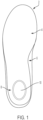
- Figure 1 shows an illustration of an insole 2 having a pod 10.
- the insole comprises a heel region 8, an arch region 6 and a ball of foot region 4.
- the pod 10 is located in the heel region 8. The positioning of the pod 10 in the heel region 8 allows the pod 10 to cushion the impact of the strike of the heel during a step.
- the pod 10 is located in the centre of insole width and in the region corresponding to a user heel would strike the insole 2.
- Figure 2 shows an example of an insole 2 having a top layer 22, a forefoot portion 24, a % length portion 20, a shell 18 and a pod 10.
- the top layer 22 comprises a memory foam material and a fabric top cloth
- the forefoot portion 24 comprises a TPE gel material
- the % length portion 20 comprises a PU foam
- the shell part 18 comprises a thermoplastic polyurethane (TPU)
- the pod 10 comprises an encapsulated liquid.
- the top layer 22 comprises a fabric material on the foot facing portion of the insole which bonded to a memory foam below.
- the heel region comprises a pod and a PU foam layer and the pod comprises an encapsulated liquid and the pod is at least partially embedded in the PU foam layer.
- the memory foam of the top layer 22 is formed from a PU material having foam bubbles.
- the memory foam has a density of 50g/cm 3 .
- the density of the memory foam may be in the range of 40g/cm 3 to 100g/cm 3 , for example 45g/cm 3 to 60g/cm 3 .
- the memory foam may have a thickness of 1.5mm to 3mm, for example 2mm to 2.5mm
- the PU foam of the % length portion 20 is selected to have a hardness from 20 Asker C to 40 Asker C, for example 25 Asker C to 35 Asker C, for example 30 Asker C.
- the thickness of the PU foam may be increased to provide addition cushioning.
- the PU foam may have a thickness of 0.5mm to 3mm, for example 1mm to 2.5mm, for example 1.5mm.
- the TPU material of the shell 18 is selected to have a hardness from 70 Shore A to 120 Shore A, for example 80 Shore A to 110 Shore A, for example 90 Shore A to 100 Shore A, for example 95 Shore A.
- the TPU material of the shell 18 may have a thickness of 1mm to 2mm, for example 1.5mm.
- the TPE gel material of the forefoot portion 24 is selected to have a hardness from 10 Asker C to 30 Asker C, for example 15 Asker C to 25 Asker C, for example 20 Asker C.
- the TPE gel material of the forefoot portion 24 may have a thickness of 2mm to 3.5mm, for example 2.5mm to 3mm.
- the ball of foot region 4, arch region 6 and heel region 8 comprise different materials to provide the appropriate support.
- the ball of foot region 4 comprises a gel layer and a memory foam layer
- the arch region 6 comprises a PU foam layer and a memory foam layer.
- the heel region 8 comprises a liquid encapsulated in the pod 10 and the pod 10 is surrounded by a PU foam and a TPU shell 18.
- the shell extends to the arch region 6 of the insole.
- the heel region comprises a top memory foam layer, a middle PU foam layer and a bottom pod 10 with the top closest to the foot facing part of the insole and the bottom closest to the shoe facing part of the insole.
- Figure 3 shows a further example of an insole 2 having a pod 10.
- the shell part 18 differs from the example illustrated in Figure 2 with the shell located in the heel region 8 and the arch region 6.
- Figure 5 illustrates the position of the pod 10 in the insole 2.
- the pod is surrounded by the PU foam on the bottom surface of the insole.
- the pod 10 is bound laterally by the PU foam of the % portion 20 and the PU foam of the % portion 20 is surrounded by the TPU material of the shell 18.
- This concentric type structure allows the liquid in the pod 10 to move as pressure is applied by the foot during foot strike.
- the pod expands laterally to accommodate the movement of the liquid in the pod 10 and redistribute the force applied to the pod 10 by the foot.
- the pod 10 is compressed vertically by the foot the liquid moves so that the pod expands laterally.
- the concentric type structure described above provides lateral resistance to the movement of the pod so that the liquid is able to move sufficiently to provide a redistribution of the force during impact whilst restricting that movement to provide sufficient stability.
- the TPU material of the shell 18 is relatively stiff to inhibit the movement of the PU foam of the % portion 20.
- the PU foam compresses between the pod and the shell as the pod expands laterally. This compression provides resistance to the expansion of the pod.
- the gap ranges from 0.8mm to 1.2mm, for example from 0.9mm to 1.1mm.
- the size of the pod is selected to target areas of pressure on the foot during impact.
- the pod is located in the heel region and the size of the pod is selected to redistribute the force from the heel during foot strike over a wider area.
- the force from the heel during foot strike peaks in the heel area of the insole and forms a peak force area. Selecting a pod size to be larger than the area of the force from heel during foot strike allows the force to be redistributed to areas away from the peak force area and therefore increases comfort to the user.
- the pod illustrated has an elliptical shape with a major axis (i.e. the longest distance from the centre to the edge of the ellipse) measures 28mm and a minor axis (i.e. the shortest distance from the centre to the edge of the ellipse) measures 18 mm.
- the pod may have a major axis from 24mm to 36mm, for example 26mm to 30mm.
- the pod may have a minor axis from 15mm to 26mm, for example 17mm to 20mm.
- the size of the pod may differ for different sizes of insole.
- the elliptical pod may have a minor axis measuring in the range 15mm to 28mm, for example from 16mm to 24mm, for example from 17mm to 22mm.
- the elliptical pod may have a major axis measuring in the range 21mm to 44 mm, for example from 22mm to 30mm, for example from 22.5mm to 25mm.
- the elliptical pod may be larger for an insole to fit a larger shoe.
- the elliptical pod may have a major axis measuring in the range 25mm to 48mm, for example from 28mm to 40mm.
- the elliptical pod may have a minor axis measuring in the range 17 mm to 31 mm, for example from 17.5 mm to 25 mm.
- the ratio of the major axis to minor axis of the pod ellipse is 1.56.
- Figures 4a, 4b and 4c show the pod 10 in more detail. As discussed above the pod encapsulates a liquid. The shape of the pod 10 and the bonding of the pod walls provides sufficient resistance to the increase in pressure associated with the impact of a user's foot on the pod during heel strike.
- FIG 4a shows the top view of the pod 10.
- the pod 10 comprises a centre portion 16, a lip 12 and a side wall 14.
- the centre portion 16 comprises a cavity for the liquid and impact during a foot strike on the centre portion will displace the liquid.
- the cavity formed by the centre portion is shown in detail in the cross-sectional view of Figure 4b . As illustrated, the liquid 13 is located in the cavity in the centre portion.
- the side wall 14 is shown in detail in Figure 4b and 4c .
- the side wall 14 extends perpendicularly from the bottom of the insole and has a thickness of 0.8mm.
- the film comprises a thermoplastic polyurethane material (TPU) and the capsule comprises a thermoplastic polyurethane material (TPU).
- FIG. 4b shows the pod being formed by a capsule 26 and a film 28.
- the capsule 26 is bonded to the film 28 at the lip 12.
- the film 28 and the capsule 26 is bonded using a high frequency weld.
- the lip 12 extends around the perimeter of the pod and provides a large surface area for the capsule 26 to bond to the film 28.
- the large surface area increases the strength of the bond between the capsule 26 and the film 28.
- the bond strength is related to the burst pressure of the pod.
- the lip has a length, measured from the edge of the pod to the end of the lip, of 4.5mm.
- the lip length may be from 2.5mm to 6.5mm, for example 3mm to 6mm, for example 3.5mm to 5.5mm, for example 4mm to 5mm.
- the lip 12 of the pod also allows the pod to be secured in the insole 2.
- the lip 12 is bonded to the PU foam of the % portion 20.
- the lip is enclosed by the % portion 20.
- the location of the pod 10 in the PU foam 20 is illustrated in Figure 4b .
- the pod is embedded in the PU foam.
- the PU foam 20 is located relative to the pod so that the PU foam is located either side of the lip and therefore embeds the pod by having PU foam on either side of the lip of the pod 10. Embedding the pod in the PU foam 20 allows the pod to be secured by the PU foam 20 and inhibits the pod from moving within the insole.
- the capsule 26 has a thickness of 0.8mm and film has a thickness of 0.5mm.
- the capsule may have a thickness ranging from 0.5mm to 1.4mm, for example 0.7mm to 1.2mm.
- the film may have a thickness ranging from 0.5mm to 1.4mm, for example 0.7mm to 1.2mm.
- the pod 10 comprises a liquid that is sealed within a capsule 26 and the film 28.
- the viscosity and the density of the liquid is selected to provide sufficient cushioning of the force from foot strike whilst also providing stability for the foot.
- the viscosity and density of the liquid and the encapsulation of the liquid allows the impact of the foot strike to be distributed over a larger area and therefore reduce the peak force on the foot during foot strike.
- the liquid has a viscosity of 0.022 m 2 /s (22,000 cSt) at 40°C and density of 0.9g/cm 3 .
- the viscosity of the liquid may range from 0.018 to 0.024 m 2 /s (18,000 to 24,000 cSt) at 40°C, for example 0.020 to 0.023 m 2 /s (20,000 to 23,000 cSt) at 40°C.
- the liquid may have a density of 0.7g/cm 3 to 1.1g/cm 3 , for example 0.8g/cm 3 to 1.0g/cm 3 .
- the insole comprises a pod located in the heel region.
- the pod may be located in other regions of the insole that correspond to areas of high-pressure during foot strike, for example the pod may be located in the ball of foot region.
- the insole comprises a single pod.
- the insole may comprise more than one pod.
- the insole may comprise a first pod in the heel region and a second pod located in the ball of foot region.
- the pod has an elliptical shape, the pod may also be circular.
- the shell is made from TPU. In other examples, the shell may be made from hard materials such as Nylon.
- the pod may be sized based on the size of the insole.
- the pod length may be 16% of the insole length and pod width 50% of the insole width.
- the pod length may range from 10% to 25% of the insole length, for example 13% to 21% of the insole length, for example 15% to 17% of the insole length.
- the pod width may range from 40% to 60% of the insole width, for example 45% to 55% of the insole width.
Landscapes
- Life Sciences & Earth Sciences (AREA)
- Chemical & Material Sciences (AREA)
- Engineering & Computer Science (AREA)
- Materials Engineering (AREA)
- Wood Science & Technology (AREA)
- Health & Medical Sciences (AREA)
- Epidemiology (AREA)
- General Health & Medical Sciences (AREA)
- Public Health (AREA)
- Footwear And Its Accessory, Manufacturing Method And Apparatuses (AREA)
Description
- The impact of foot strike can lead to large forces on joints in the body. An insole can be used to reduce the impact of foot strike and therefore can lessen the impact of steps on the body. For example, during each step the foot impacts the ground. This impact may be referred to as foot strike. The foot strike leads to a force on the foot and body due to the impact of each step.
- An insole reduces the impact by using materials that cushion the force associated with a step. The comfort of an insole for a user may be associated with how each step is cushioned and the force distributed in the insole. In general, the cushioning of an insole is dependent upon how a force is cushioned and the area over which the force is distributed.
- Document
US6176025B1 discloses an insole according to the preamble of claim 1. - The present disclosure describes an insole that distributes the force associated with foot strike to provide comfort to the user. The distribution of the force by the insole reduces the peak force on the foot. The insole provides cushioning upon impact over both a sustained period of time and during repeated uses of the insole. The present invention is defined by an insole according to the appended claim 1. Preferred embodiments are defined by the appended dependent claims.
- Aspects of the disclosure are also described in detail, by way of example only, with reference to the accompanying drawings, in which:
-
Figure 1 shows an illustrative view of an insole having a pod; -
Figure 2 shows an exploded view of the different layers of an example of the insole; -
Figure 3 shows an exploded view of the different layers of a further example of an insole; -
Figure 4a shows a pod to be placed in an insole; -
Figure 4b shows a sectional view of the pod shown inFigure 4a ; -
Figure 4c shows a side view of the pod shown inFigure 4a ; and -
Figure 5 shows an example of the pod in situ in an insole. - Embodiments will now be described with reference to the Figures.
-
Figure 1 shows an illustration of aninsole 2 having apod 10. The insole comprises aheel region 8, anarch region 6 and a ball offoot region 4. - The
pod 10 is located in theheel region 8. The positioning of thepod 10 in theheel region 8 allows thepod 10 to cushion the impact of the strike of the heel during a step. - In the example illustrated in
Figure 1 , thepod 10 is located in the centre of insole width and in the region corresponding to a user heel would strike theinsole 2. -
Figure 2 shows an example of aninsole 2 having atop layer 22, aforefoot portion 24, a %length portion 20, ashell 18 and apod 10. - In the example illustrated, the
top layer 22 comprises a memory foam material and a fabric top cloth, theforefoot portion 24 comprises a TPE gel material, the %length portion 20 comprises a PU foam, theshell part 18 comprises a thermoplastic polyurethane (TPU) and thepod 10 comprises an encapsulated liquid. In this example, thetop layer 22 comprises a fabric material on the foot facing portion of the insole which bonded to a memory foam below. - According to the invention, the heel region comprises a pod and a PU foam layer and the pod comprises an encapsulated liquid and the pod is at least partially embedded in the PU foam layer.
- The memory foam of the
top layer 22 is formed from a PU material having foam bubbles. - In an example the memory foam has a density of 50g/cm3. The density of the memory foam may be in the range of 40g/cm3 to 100g/cm3, for example 45g/cm3 to 60g/cm3. The memory foam may have a thickness of 1.5mm to 3mm, for example 2mm to 2.5mm
- In an example, the PU foam of the %
length portion 20 is selected to have a hardness from 20 Asker C to 40 Asker C, for example 25 Asker C to 35 Asker C, for example 30 Asker C. The thickness of the PU foam may be increased to provide addition cushioning. For example, the PU foam may have a thickness of 0.5mm to 3mm, for example 1mm to 2.5mm, for example 1.5mm. - In an example, the TPU material of the
shell 18 is selected to have a hardness from 70 Shore A to 120 Shore A, for example 80 Shore A to 110 Shore A, for example 90 Shore A to 100 Shore A, for example 95 Shore A. The TPU material of theshell 18 may have a thickness of 1mm to 2mm, for example 1.5mm. - In an example, the TPE gel material of the
forefoot portion 24 is selected to have a hardness from 10 Asker C to 30 Asker C, for example 15 Asker C to 25 Asker C, for example 20 Asker C. The TPE gel material of theforefoot portion 24 may have a thickness of 2mm to 3.5mm, for example 2.5mm to 3mm. - As illustrated in
Figure 2 , the ball offoot region 4,arch region 6 andheel region 8 comprise different materials to provide the appropriate support. In this example, the ball offoot region 4 comprises a gel layer and a memory foam layer, thearch region 6 comprises a PU foam layer and a memory foam layer. Theheel region 8 comprises a liquid encapsulated in thepod 10 and thepod 10 is surrounded by a PU foam and aTPU shell 18. In the example shown inFigure 2 , the shell extends to thearch region 6 of the insole. - In the example illustrated, the heel region comprises a top memory foam layer, a middle PU foam layer and a
bottom pod 10 with the top closest to the foot facing part of the insole and the bottom closest to the shoe facing part of the insole. -
Figure 3 shows a further example of aninsole 2 having apod 10. In this example, theshell part 18 differs from the example illustrated inFigure 2 with the shell located in theheel region 8 and thearch region 6. -
Figure 5 illustrates the position of thepod 10 in theinsole 2. As illustrated, the pod is surrounded by the PU foam on the bottom surface of the insole. For example, thepod 10 is bound laterally by the PU foam of the %portion 20 and the PU foam of the %portion 20 is surrounded by the TPU material of theshell 18. This concentric type structure allows the liquid in thepod 10 to move as pressure is applied by the foot during foot strike. For example, as a force is applied to thepod 10 by the foot the pod expands laterally to accommodate the movement of the liquid in thepod 10 and redistribute the force applied to thepod 10 by the foot. For example, as thepod 10 is compressed vertically by the foot the liquid moves so that the pod expands laterally. The concentric type structure described above provides lateral resistance to the movement of the pod so that the liquid is able to move sufficiently to provide a redistribution of the force during impact whilst restricting that movement to provide sufficient stability. - In the example illustrated, the TPU material of the
shell 18 is relatively stiff to inhibit the movement of the PU foam of the %portion 20. The PU foam compresses between the pod and the shell as the pod expands laterally. This compression provides resistance to the expansion of the pod. - In the example shown in
Figure 5 , there is a gap of 1mm between the pod and the PU foam on the bottom surface of the insole. This gap allows the pod to expand without the resistance of the PU foam inhibiting the movement. In accordance with the present invention as defined in claim 1 as appended hereto, the gap ranges from 0.8mm to 1.2mm, for example from 0.9mm to 1.1mm. - The size of the pod is selected to target areas of pressure on the foot during impact. In the examples illustrated above, the pod is located in the heel region and the size of the pod is selected to redistribute the force from the heel during foot strike over a wider area. In general, the force from the heel during foot strike peaks in the heel area of the insole and forms a peak force area. Selecting a pod size to be larger than the area of the force from heel during foot strike allows the force to be redistributed to areas away from the peak force area and therefore increases comfort to the user.
- The pod illustrated has an elliptical shape with a major axis (i.e. the longest distance from the centre to the edge of the ellipse) measures 28mm and a minor axis (i.e. the shortest distance from the centre to the edge of the ellipse) measures 18 mm. The pod may have a major axis from 24mm to 36mm, for example 26mm to 30mm. The pod may have a minor axis from 15mm to 26mm, for example 17mm to 20mm.
- The size of the pod may differ for different sizes of insole. For example, for an insole sized to fit a shoe sized 3.5 UK the elliptical pod may have a minor axis measuring in the range 15mm to 28mm, for example from 16mm to 24mm, for example from 17mm to 22mm. The elliptical pod may have a major axis measuring in the range 21mm to 44 mm, for example from 22mm to 30mm, for example from 22.5mm to 25mm.
- The elliptical pod may be larger for an insole to fit a larger shoe. For example, for an insole sized to fit a shoe sized 8 UK the elliptical pod the elliptical pod may have a major axis measuring in the range 25mm to 48mm, for example from 28mm to 40mm. The elliptical pod may have a minor axis measuring in the range 17 mm to 31 mm, for example from 17.5 mm to 25 mm.
- In the example illustrated, the ratio of the major axis to minor axis of the pod ellipse is 1.56.
Figures 4a, 4b and 4c show thepod 10 in more detail. As discussed above the pod encapsulates a liquid. The shape of thepod 10 and the bonding of the pod walls provides sufficient resistance to the increase in pressure associated with the impact of a user's foot on the pod during heel strike. -
Figure 4a shows the top view of thepod 10. Thepod 10 comprises acentre portion 16, alip 12 and aside wall 14. Thecentre portion 16 comprises a cavity for the liquid and impact during a foot strike on the centre portion will displace the liquid. The cavity formed by the centre portion is shown in detail in the cross-sectional view ofFigure 4b . As illustrated, the liquid 13 is located in the cavity in the centre portion. - The
side wall 14 is shown in detail inFigure 4b and 4c . In the example illustrated, theside wall 14 extends perpendicularly from the bottom of the insole and has a thickness of 0.8mm. In the example illustrated the film comprises a thermoplastic polyurethane material (TPU) and the capsule comprises a thermoplastic polyurethane material (TPU). - The cross-sectional view shown in
Figure 4b shows the pod being formed by acapsule 26 and afilm 28. Thecapsule 26 is bonded to thefilm 28 at thelip 12. In this example thefilm 28 and thecapsule 26 is bonded using a high frequency weld. - The
lip 12 extends around the perimeter of the pod and provides a large surface area for thecapsule 26 to bond to thefilm 28. The large surface area increases the strength of the bond between thecapsule 26 and thefilm 28. The bond strength is related to the burst pressure of the pod. In the example illustrated the lip has a length, measured from the edge of the pod to the end of the lip, of 4.5mm. The lip length may be from 2.5mm to 6.5mm, for example 3mm to 6mm, for example 3.5mm to 5.5mm, for example 4mm to 5mm. - The
lip 12 of the pod also allows the pod to be secured in theinsole 2. In the example illustrated inFigure 5 , thelip 12 is bonded to the PU foam of the% portion 20. As illustrated inFigure 5 , the lip is enclosed by the% portion 20. - The location of the
pod 10 in thePU foam 20 is illustrated inFigure 4b . In this example, the pod is embedded in the PU foam. As illustrated inFigure 4b , thePU foam 20 is located relative to the pod so that the PU foam is located either side of the lip and therefore embeds the pod by having PU foam on either side of the lip of thepod 10. Embedding the pod in thePU foam 20 allows the pod to be secured by thePU foam 20 and inhibits the pod from moving within the insole. - In the example illustrated, the
capsule 26 has a thickness of 0.8mm and film has a thickness of 0.5mm. The capsule may have a thickness ranging from 0.5mm to 1.4mm, for example 0.7mm to 1.2mm. The film may have a thickness ranging from 0.5mm to 1.4mm, for example 0.7mm to 1.2mm. - The
pod 10 comprises a liquid that is sealed within acapsule 26 and thefilm 28. The viscosity and the density of the liquid is selected to provide sufficient cushioning of the force from foot strike whilst also providing stability for the foot. The viscosity and density of the liquid and the encapsulation of the liquid allows the impact of the foot strike to be distributed over a larger area and therefore reduce the peak force on the foot during foot strike. In an example, the liquid has a viscosity of 0.022 m2/s (22,000 cSt) at 40°C and density of 0.9g/cm3. - The viscosity of the liquid may range from 0.018 to 0.024 m2/s (18,000 to 24,000 cSt) at 40°C, for example 0.020 to 0.023 m2/s (20,000 to 23,000 cSt) at 40°C. The liquid may have a density of 0.7g/cm3 to 1.1g/cm3, for example 0.8g/cm3 to 1.0g/cm3.
- According to the invention, the insole comprises a pod located in the heel region.
- In further examples the pod may be located in other regions of the insole that correspond to areas of high-pressure during foot strike, for example the pod may be located in the ball of foot region.
- In the examples illustrated above, the insole comprises a single pod. In further examples, the insole may comprise more than one pod. For example, the insole may comprise a first pod in the heel region and a second pod located in the ball of foot region.
- In the examples described above the pod has an elliptical shape, the pod may also be circular.
- In the examples above, the shell is made from TPU. In other examples, the shell may be made from hard materials such as Nylon.
- In an example, the pod may be sized based on the size of the insole. For example, the pod length may be 16% of the insole length and pod width 50% of the insole width. The pod length may range from 10% to 25% of the insole length, for example 13% to 21% of the insole length, for example 15% to 17% of the insole length. The pod width may range from 40% to 60% of the insole width, for example 45% to 55% of the insole width.
- Further modifications and developments can be made without departing from the scope of the invention as defined by the appended claims.
Claims (15)
- An insole (2) comprising a heel region (8), an arch region (6) and a forefoot region (4);the heel region (8) comprising a pod (10) and a PU foam layer;wherein the pod (10) comprises an encapsulated liquid, and the pod (10) is at least partially embedded in the PU foam layer and surrounded by the PU foam on a bottom surface of the insole (2);characterised in that the PU foam is separated from the pod (10) on the bottom surface by a gap of 0.8mm to 1.2mm.
- The insole (2) of claim 1, wherein the liquid has a viscosity 0.018 to 0.024 m2/s (18,000 to 24,000 cSt) at 40°C and a density of 0.7g/cm3 to 1.1g/ 3 cm .
- The insole (2) of any preceding claim, wherein the PU foam has a hardness from 20 Asker C to 40 Asker C.
- The insole (2) of any preceding claim, further comprising a memory foam layer;
wherein the heel region (8) comprises a top memory foam layer, a middle PU foam layer and a bottom pod with the top closest to the foot facing part of the insole (2). - The insole (2) of any preceding claim, wherein the pod (10) comprises a centre portion (16) having a cavity for holding the liquid and a lip (12) extending around the perimeter of the pod (10);
wherein the lip (12) is at least partially embedded by the PU foam. - The insole (2) of claim 1,
wherein the pod (10) is configured to redistribute an impact of a foot on the heel region (8) over a wider area, and is surrounded by the PU foam and a TPU shell on the bottom surface of the insole (2) in a concentric arrangement. - The insole (2) of claim 6, wherein the liquid has a viscosity 0.018 to 0.024 m2/s (18,000 to 24,000 cSt) at 40°C and a density of 0.7g/cm3 to 1.1g/ cm3.
- The insole (2) of claim 6 or claim 7, wherein the pod (10) is elliptical in shape and comprises a minor axis from 15mm to 26mm.
- The insole (2) of any preceding claim, wherein:the pod (10) comprises a centre portion (16) having a cavity for holding the liquid and a lip (12) extending around the perimeter of the pod (10);the pod (10) is formed from a capsule and a film, wherein the capsule is bonded to the film along the lip (12) to form the cavity;wherein the capsule comprises a thermoplastic polyurethane material and the film comprises a thermoplastic polyurethane material and the capsule is bonded to the film, and optionally wherein the capsule is bonded to the film using a high frequency weld.
- The insole (2) of claim 9, wherein the capsule has a thickness ranging from 0.5mm to 1.4mm and the film has thickness ranging from 0.5mm to 1.4mm.
- The insole (2) of claim 9 or claim 10, wherein the lip (12) has a length, measured from the edge of the pod (10) to the end of the lip (12), of 2.5mm to 6.5mm.
- The insole (2) of any one of claims 9 to 11, wherein the lip (12) extends around the perimeter of the pod (10).
- The insole (2) of any one of claims 9 to 12, wherein the pod (10) comprises a side wall (14) extending perpendicularly from the bottom of the insole (2) and has a thickness of 0.8mm.
- The insole (2) of any one of claims 9 to 13, wherein the pod (10) is configured to be bonded to the insole (2) by bonding the lip (12) to the insole (2).
- The insole (2) of any one of claims 9 to 14, wherein the pod (10) holds a liquid having a viscosity of 0.018 to 0.024 m2/s (18,000 to 24,000 cSt) at 40°C and a density of 0.7g/cm3 to 1.1g/cm3.
Applications Claiming Priority (2)
| Application Number | Priority Date | Filing Date | Title |
|---|---|---|---|
| GB2018732.4A GB2602960B (en) | 2020-11-27 | 2020-11-27 | Insole |
| PCT/GB2021/053087 WO2022112787A1 (en) | 2020-11-27 | 2021-11-26 | Insole |
Publications (2)
| Publication Number | Publication Date |
|---|---|
| EP4250999A1 EP4250999A1 (en) | 2023-10-04 |
| EP4250999B1 true EP4250999B1 (en) | 2025-01-01 |
Family
ID=74099907
Family Applications (1)
| Application Number | Title | Priority Date | Filing Date |
|---|---|---|---|
| EP21823989.5A Active EP4250999B1 (en) | 2020-11-27 | 2021-11-26 | Insole |
Country Status (6)
| Country | Link |
|---|---|
| US (1) | US12268279B2 (en) |
| EP (1) | EP4250999B1 (en) |
| JP (1) | JP2023553303A (en) |
| AU (1) | AU2021388965B2 (en) |
| GB (1) | GB2602960B (en) |
| WO (1) | WO2022112787A1 (en) |
Family Cites Families (11)
| Publication number | Priority date | Publication date | Assignee | Title |
|---|---|---|---|---|
| US6205684B1 (en) | 1998-11-13 | 2001-03-27 | Zephyr Athletic Footwear, Inc. | Strike pad assembly |
| US6176025B1 (en) * | 1999-05-28 | 2001-01-23 | Spalding Sports Worldwide, Inc. | Cushioning system for golf shoes |
| US7020990B2 (en) * | 2004-01-13 | 2006-04-04 | M. Steven Khoury | Orthopedic device for distributing pressure |
| US20050241185A1 (en) * | 2004-04-28 | 2005-11-03 | Flood Michael T | Shoe insert |
| US7200955B2 (en) * | 2004-06-04 | 2007-04-10 | Nike, Inc. | Article of footwear incorporating a sole structure with compressible inserts |
| US20070033835A1 (en) | 2005-08-02 | 2007-02-15 | Bray Walter T Jr | Insole arrangement; footwear with insole arrangement; and, method of preparation |
| US7484319B2 (en) | 2005-08-12 | 2009-02-03 | Spenco Medical Corporation | Shoe insole |
| ITPD20070003A1 (en) * | 2007-01-04 | 2008-07-05 | Alberto Del Biondi S P A | SHOULDED INSOLE FOR FOOTWEAR |
| US8490297B2 (en) * | 2007-10-11 | 2013-07-23 | Ginger Guerra | Integrated, cumulative-force-mitigating apparatus, system, and method for substantially-inclined shoes |
| US20130008050A1 (en) * | 2011-07-07 | 2013-01-10 | Michel Marc | Shoe Insole |
| US20160066647A1 (en) * | 2014-09-09 | 2016-03-10 | Totes Isotoner Corporation | Footwear insoles incorporating gel-infused memory foam |
-
2020
- 2020-11-27 GB GB2018732.4A patent/GB2602960B/en active Active
-
2021
- 2021-11-26 AU AU2021388965A patent/AU2021388965B2/en active Active
- 2021-11-26 WO PCT/GB2021/053087 patent/WO2022112787A1/en not_active Ceased
- 2021-11-26 US US18/037,755 patent/US12268279B2/en active Active
- 2021-11-26 EP EP21823989.5A patent/EP4250999B1/en active Active
- 2021-11-26 JP JP2023531061A patent/JP2023553303A/en active Pending
Also Published As
| Publication number | Publication date |
|---|---|
| AU2021388965A9 (en) | 2024-10-24 |
| AU2021388965B2 (en) | 2024-12-05 |
| US20230413947A1 (en) | 2023-12-28 |
| GB2602960A (en) | 2022-07-27 |
| WO2022112787A1 (en) | 2022-06-02 |
| AU2021388965A1 (en) | 2023-06-15 |
| EP4250999A1 (en) | 2023-10-04 |
| US12268279B2 (en) | 2025-04-08 |
| JP2023553303A (en) | 2023-12-21 |
| GB2602960B (en) | 2023-10-25 |
| GB202018732D0 (en) | 2021-01-13 |
Similar Documents
| Publication | Publication Date | Title |
|---|---|---|
| US11540594B2 (en) | Footwear bladder system | |
| CN110662443B (en) | Midsole with graded response | |
| US11259596B2 (en) | Midsole system with graded response | |
| US5595004A (en) | Shoe sole including a peripherally-disposed cushioning bladder | |
| US5367792A (en) | Shoe sole construction | |
| EP1916917B1 (en) | Footwear sole component with an insert | |
| EP3629809B1 (en) | Article of footwear with auxetic sole structure having a filled auxetic aperture | |
| US20110162232A1 (en) | Sole structure | |
| WO2010049983A1 (en) | Shoe sole suitable for suppressing pronation | |
| JP2014521463A (en) | Shoe sole for shock absorption and energy return | |
| EP2480106B1 (en) | INNER MULTILAYER SOLE INTENDED FOR INSERTION IN FOOTWEAR AND SIMILAR ELEMENTS | |
| AU2021388965B2 (en) | Insole | |
| KR20100090047A (en) | Air bag for midsole and shoes | |
| KR101167106B1 (en) | Sole of shoe | |
| JP7326797B2 (en) | Insole-type electronic device and method for manufacturing insole-type electronic device | |
| KR100578331B1 (en) | Air bag for shoes and its manufacturing method | |
| KR102220593B1 (en) | A Gas Flowing Type of a Article for Protecting a Sole | |
| WO2011014143A1 (en) | Heel construction for footwear | |
| WO2003082040A1 (en) | Sole for footwear |
Legal Events
| Date | Code | Title | Description |
|---|---|---|---|
| STAA | Information on the status of an ep patent application or granted ep patent |
Free format text: STATUS: UNKNOWN |
|
| STAA | Information on the status of an ep patent application or granted ep patent |
Free format text: STATUS: THE INTERNATIONAL PUBLICATION HAS BEEN MADE |
|
| PUAI | Public reference made under article 153(3) epc to a published international application that has entered the european phase |
Free format text: ORIGINAL CODE: 0009012 |
|
| STAA | Information on the status of an ep patent application or granted ep patent |
Free format text: STATUS: REQUEST FOR EXAMINATION WAS MADE |
|
| 17P | Request for examination filed |
Effective date: 20230505 |
|
| AK | Designated contracting states |
Kind code of ref document: A1 Designated state(s): AL AT BE BG CH CY CZ DE DK EE ES FI FR GB GR HR HU IE IS IT LI LT LU LV MC MK MT NL NO PL PT RO RS SE SI SK SM TR |
|
| DAV | Request for validation of the european patent (deleted) | ||
| DAX | Request for extension of the european patent (deleted) | ||
| GRAP | Despatch of communication of intention to grant a patent |
Free format text: ORIGINAL CODE: EPIDOSNIGR1 |
|
| STAA | Information on the status of an ep patent application or granted ep patent |
Free format text: STATUS: GRANT OF PATENT IS INTENDED |
|
| INTG | Intention to grant announced |
Effective date: 20240814 |
|
| RBV | Designated contracting states (corrected) |
Designated state(s): AL AT BE BG CH CY CZ DE DK EE ES FI FR GR HR HU IE IS IT LI LT LU LV MC MK MT NL NO PL PT RO RS SE SI SK SM TR |
|
| GRAS | Grant fee paid |
Free format text: ORIGINAL CODE: EPIDOSNIGR3 |
|
| GRAA | (expected) grant |
Free format text: ORIGINAL CODE: 0009210 |
|
| STAA | Information on the status of an ep patent application or granted ep patent |
Free format text: STATUS: THE PATENT HAS BEEN GRANTED |
|
| AK | Designated contracting states |
Kind code of ref document: B1 Designated state(s): AL AT BE BG CH CY CZ DE DK EE ES FI FR GR HR HU IE IS IT LI LT LU LV MC MK MT NL NO PL PT RO RS SE SI SK SM TR |
|
| REG | Reference to a national code |
Ref country code: CH Ref legal event code: EP |
|
| REG | Reference to a national code |
Ref country code: DE Ref legal event code: R096 Ref document number: 602021024426 Country of ref document: DE |
|
| REG | Reference to a national code |
Ref country code: IE Ref legal event code: FG4D |
|
| REG | Reference to a national code |
Ref country code: LT Ref legal event code: MG9D |
|
| REG | Reference to a national code |
Ref country code: NL Ref legal event code: MP Effective date: 20250101 |
|
| REG | Reference to a national code |
Ref country code: AT Ref legal event code: MK05 Ref document number: 1755337 Country of ref document: AT Kind code of ref document: T Effective date: 20250101 |
|
| PG25 | Lapsed in a contracting state [announced via postgrant information from national office to epo] |
Ref country code: NL Free format text: LAPSE BECAUSE OF FAILURE TO SUBMIT A TRANSLATION OF THE DESCRIPTION OR TO PAY THE FEE WITHIN THE PRESCRIBED TIME-LIMIT Effective date: 20250101 |
|
| PG25 | Lapsed in a contracting state [announced via postgrant information from national office to epo] |
Ref country code: FI Free format text: LAPSE BECAUSE OF FAILURE TO SUBMIT A TRANSLATION OF THE DESCRIPTION OR TO PAY THE FEE WITHIN THE PRESCRIBED TIME-LIMIT Effective date: 20250101 |
|
| PG25 | Lapsed in a contracting state [announced via postgrant information from national office to epo] |
Ref country code: PL Free format text: LAPSE BECAUSE OF FAILURE TO SUBMIT A TRANSLATION OF THE DESCRIPTION OR TO PAY THE FEE WITHIN THE PRESCRIBED TIME-LIMIT Effective date: 20250101 |
|
| PG25 | Lapsed in a contracting state [announced via postgrant information from national office to epo] |
Ref country code: ES Free format text: LAPSE BECAUSE OF FAILURE TO SUBMIT A TRANSLATION OF THE DESCRIPTION OR TO PAY THE FEE WITHIN THE PRESCRIBED TIME-LIMIT Effective date: 20250101 |
|
| PG25 | Lapsed in a contracting state [announced via postgrant information from national office to epo] |
Ref country code: IS Free format text: LAPSE BECAUSE OF FAILURE TO SUBMIT A TRANSLATION OF THE DESCRIPTION OR TO PAY THE FEE WITHIN THE PRESCRIBED TIME-LIMIT Effective date: 20250501 Ref country code: NO Free format text: LAPSE BECAUSE OF FAILURE TO SUBMIT A TRANSLATION OF THE DESCRIPTION OR TO PAY THE FEE WITHIN THE PRESCRIBED TIME-LIMIT Effective date: 20250401 |
|
| PG25 | Lapsed in a contracting state [announced via postgrant information from national office to epo] |
Ref country code: HR Free format text: LAPSE BECAUSE OF FAILURE TO SUBMIT A TRANSLATION OF THE DESCRIPTION OR TO PAY THE FEE WITHIN THE PRESCRIBED TIME-LIMIT Effective date: 20250101 |
|
| PG25 | Lapsed in a contracting state [announced via postgrant information from national office to epo] |
Ref country code: LV Free format text: LAPSE BECAUSE OF FAILURE TO SUBMIT A TRANSLATION OF THE DESCRIPTION OR TO PAY THE FEE WITHIN THE PRESCRIBED TIME-LIMIT Effective date: 20250101 Ref country code: PT Free format text: LAPSE BECAUSE OF FAILURE TO SUBMIT A TRANSLATION OF THE DESCRIPTION OR TO PAY THE FEE WITHIN THE PRESCRIBED TIME-LIMIT Effective date: 20250502 |
|
| PG25 | Lapsed in a contracting state [announced via postgrant information from national office to epo] |
Ref country code: BG Free format text: LAPSE BECAUSE OF FAILURE TO SUBMIT A TRANSLATION OF THE DESCRIPTION OR TO PAY THE FEE WITHIN THE PRESCRIBED TIME-LIMIT Effective date: 20250101 Ref country code: GR Free format text: LAPSE BECAUSE OF FAILURE TO SUBMIT A TRANSLATION OF THE DESCRIPTION OR TO PAY THE FEE WITHIN THE PRESCRIBED TIME-LIMIT Effective date: 20250402 |
|
| PG25 | Lapsed in a contracting state [announced via postgrant information from national office to epo] |
Ref country code: AT Free format text: LAPSE BECAUSE OF FAILURE TO SUBMIT A TRANSLATION OF THE DESCRIPTION OR TO PAY THE FEE WITHIN THE PRESCRIBED TIME-LIMIT Effective date: 20250101 |
|
| PG25 | Lapsed in a contracting state [announced via postgrant information from national office to epo] |
Ref country code: CZ Free format text: LAPSE BECAUSE OF FAILURE TO SUBMIT A TRANSLATION OF THE DESCRIPTION OR TO PAY THE FEE WITHIN THE PRESCRIBED TIME-LIMIT Effective date: 20250101 |
|
| PG25 | Lapsed in a contracting state [announced via postgrant information from national office to epo] |
Ref country code: SE Free format text: LAPSE BECAUSE OF FAILURE TO SUBMIT A TRANSLATION OF THE DESCRIPTION OR TO PAY THE FEE WITHIN THE PRESCRIBED TIME-LIMIT Effective date: 20250101 |
|
| REG | Reference to a national code |
Ref country code: DE Ref legal event code: R097 Ref document number: 602021024426 Country of ref document: DE |
|
| PG25 | Lapsed in a contracting state [announced via postgrant information from national office to epo] |
Ref country code: SM Free format text: LAPSE BECAUSE OF FAILURE TO SUBMIT A TRANSLATION OF THE DESCRIPTION OR TO PAY THE FEE WITHIN THE PRESCRIBED TIME-LIMIT Effective date: 20250101 |
|
| PG25 | Lapsed in a contracting state [announced via postgrant information from national office to epo] |
Ref country code: DK Free format text: LAPSE BECAUSE OF FAILURE TO SUBMIT A TRANSLATION OF THE DESCRIPTION OR TO PAY THE FEE WITHIN THE PRESCRIBED TIME-LIMIT Effective date: 20250101 |
|
| PG25 | Lapsed in a contracting state [announced via postgrant information from national office to epo] |
Ref country code: IT Free format text: LAPSE BECAUSE OF FAILURE TO SUBMIT A TRANSLATION OF THE DESCRIPTION OR TO PAY THE FEE WITHIN THE PRESCRIBED TIME-LIMIT Effective date: 20250101 |
|
| PG25 | Lapsed in a contracting state [announced via postgrant information from national office to epo] |
Ref country code: EE Free format text: LAPSE BECAUSE OF FAILURE TO SUBMIT A TRANSLATION OF THE DESCRIPTION OR TO PAY THE FEE WITHIN THE PRESCRIBED TIME-LIMIT Effective date: 20250101 |
|
| PG25 | Lapsed in a contracting state [announced via postgrant information from national office to epo] |
Ref country code: RO Free format text: LAPSE BECAUSE OF FAILURE TO SUBMIT A TRANSLATION OF THE DESCRIPTION OR TO PAY THE FEE WITHIN THE PRESCRIBED TIME-LIMIT Effective date: 20250101 |
|
| PG25 | Lapsed in a contracting state [announced via postgrant information from national office to epo] |
Ref country code: SK Free format text: LAPSE BECAUSE OF FAILURE TO SUBMIT A TRANSLATION OF THE DESCRIPTION OR TO PAY THE FEE WITHIN THE PRESCRIBED TIME-LIMIT Effective date: 20250101 |
|
| PLBE | No opposition filed within time limit |
Free format text: ORIGINAL CODE: 0009261 |
|
| STAA | Information on the status of an ep patent application or granted ep patent |
Free format text: STATUS: NO OPPOSITION FILED WITHIN TIME LIMIT |
|
| 26N | No opposition filed |
Effective date: 20251002 |
|
| PGFP | Annual fee paid to national office [announced via postgrant information from national office to epo] |
Ref country code: DE Payment date: 20251128 Year of fee payment: 5 |
|
| PGFP | Annual fee paid to national office [announced via postgrant information from national office to epo] |
Ref country code: FR Payment date: 20251125 Year of fee payment: 5 |