EP4250886A1 - Ventilation and heat dissipation apparatus of wind power boosting rotor - Google Patents
Ventilation and heat dissipation apparatus of wind power boosting rotor Download PDFInfo
- Publication number
- EP4250886A1 EP4250886A1 EP21893235.8A EP21893235A EP4250886A1 EP 4250886 A1 EP4250886 A1 EP 4250886A1 EP 21893235 A EP21893235 A EP 21893235A EP 4250886 A1 EP4250886 A1 EP 4250886A1
- Authority
- EP
- European Patent Office
- Prior art keywords
- heat dissipation
- shielding plate
- rain shielding
- ventilation
- top cover
- Prior art date
- Legal status (The legal status is an assumption and is not a legal conclusion. Google has not performed a legal analysis and makes no representation as to the accuracy of the status listed.)
- Granted
Links
Images



Classifications
-
- H—ELECTRICITY
- H02—GENERATION; CONVERSION OR DISTRIBUTION OF ELECTRIC POWER
- H02K—DYNAMO-ELECTRIC MACHINES
- H02K9/00—Arrangements for cooling or ventilating
- H02K9/02—Arrangements for cooling or ventilating by ambient air flowing through the machine
-
- H—ELECTRICITY
- H05—ELECTRIC TECHNIQUES NOT OTHERWISE PROVIDED FOR
- H05K—PRINTED CIRCUITS; CASINGS OR CONSTRUCTIONAL DETAILS OF ELECTRIC APPARATUS; MANUFACTURE OF ASSEMBLAGES OF ELECTRICAL COMPONENTS
- H05K7/00—Constructional details common to different types of electric apparatus
- H05K7/20—Modifications to facilitate cooling, ventilating, or heating
- H05K7/20009—Modifications to facilitate cooling, ventilating, or heating using a gaseous coolant in electronic enclosures
- H05K7/20127—Natural convection
-
- F—MECHANICAL ENGINEERING; LIGHTING; HEATING; WEAPONS; BLASTING
- F04—POSITIVE - DISPLACEMENT MACHINES FOR LIQUIDS; PUMPS FOR LIQUIDS OR ELASTIC FLUIDS
- F04D—NON-POSITIVE-DISPLACEMENT PUMPS
- F04D29/00—Details, component parts, or accessories
- F04D29/40—Casings; Connections of working fluid
- F04D29/52—Casings; Connections of working fluid for axial pumps
- F04D29/54—Fluid-guiding means, e.g. diffusers
- F04D29/541—Specially adapted for elastic fluid pumps
-
- B—PERFORMING OPERATIONS; TRANSPORTING
- B63—SHIPS OR OTHER WATERBORNE VESSELS; RELATED EQUIPMENT
- B63H—MARINE PROPULSION OR STEERING
- B63H9/00—Marine propulsion provided directly by wind power
- B63H9/02—Marine propulsion provided directly by wind power using Magnus effect
-
- B—PERFORMING OPERATIONS; TRANSPORTING
- B63—SHIPS OR OTHER WATERBORNE VESSELS; RELATED EQUIPMENT
- B63J—AUXILIARIES ON VESSELS
- B63J2/00—Arrangements of ventilation, heating, cooling, or air-conditioning
- B63J2/02—Ventilation; Air-conditioning
- B63J2/10—Ventilating-shafts; Air-scoops
-
- F—MECHANICAL ENGINEERING; LIGHTING; HEATING; WEAPONS; BLASTING
- F03—MACHINES OR ENGINES FOR LIQUIDS; WIND, SPRING, OR WEIGHT MOTORS; PRODUCING MECHANICAL POWER OR A REACTIVE PROPULSIVE THRUST, NOT OTHERWISE PROVIDED FOR
- F03D—WIND MOTORS
- F03D3/00—Wind motors with rotation axis substantially perpendicular to the air flow entering the rotor
- F03D3/005—Wind motors with rotation axis substantially perpendicular to the air flow entering the rotor the axis being vertical
- F03D3/007—Wind motors with rotation axis substantially perpendicular to the air flow entering the rotor the axis being vertical using the Magnus effect
-
- F—MECHANICAL ENGINEERING; LIGHTING; HEATING; WEAPONS; BLASTING
- F03—MACHINES OR ENGINES FOR LIQUIDS; WIND, SPRING, OR WEIGHT MOTORS; PRODUCING MECHANICAL POWER OR A REACTIVE PROPULSIVE THRUST, NOT OTHERWISE PROVIDED FOR
- F03D—WIND MOTORS
- F03D9/00—Adaptations of wind motors for special use; Combinations of wind motors with apparatus driven thereby; Wind motors specially adapted for installation in particular locations
- F03D9/30—Wind motors specially adapted for installation in particular locations
- F03D9/32—Wind motors specially adapted for installation in particular locations on moving objects, e.g. vehicles
-
- F—MECHANICAL ENGINEERING; LIGHTING; HEATING; WEAPONS; BLASTING
- F04—POSITIVE - DISPLACEMENT MACHINES FOR LIQUIDS; PUMPS FOR LIQUIDS OR ELASTIC FLUIDS
- F04D—NON-POSITIVE-DISPLACEMENT PUMPS
- F04D29/00—Details, component parts, or accessories
- F04D29/60—Mounting; Assembling; Disassembling
- F04D29/601—Mounting; Assembling; Disassembling specially adapted for elastic fluid pumps
- F04D29/602—Mounting in cavities
-
- H—ELECTRICITY
- H02—GENERATION; CONVERSION OR DISTRIBUTION OF ELECTRIC POWER
- H02K—DYNAMO-ELECTRIC MACHINES
- H02K5/00—Casings; Enclosures; Supports
- H02K5/04—Casings or enclosures characterised by the shape, form or construction thereof
-
- H—ELECTRICITY
- H02—GENERATION; CONVERSION OR DISTRIBUTION OF ELECTRIC POWER
- H02K—DYNAMO-ELECTRIC MACHINES
- H02K5/00—Casings; Enclosures; Supports
- H02K5/04—Casings or enclosures characterised by the shape, form or construction thereof
- H02K5/10—Casings or enclosures characterised by the shape, form or construction thereof with arrangements for protection from ingress, e.g. water or fingers
-
- H—ELECTRICITY
- H02—GENERATION; CONVERSION OR DISTRIBUTION OF ELECTRIC POWER
- H02K—DYNAMO-ELECTRIC MACHINES
- H02K5/00—Casings; Enclosures; Supports
- H02K5/04—Casings or enclosures characterised by the shape, form or construction thereof
- H02K5/20—Casings or enclosures characterised by the shape, form or construction thereof with channels or ducts for flow of cooling medium
- H02K5/207—Casings or enclosures characterised by the shape, form or construction thereof with channels or ducts for flow of cooling medium with openings in the casing specially adapted for ambient air
-
- H—ELECTRICITY
- H02—GENERATION; CONVERSION OR DISTRIBUTION OF ELECTRIC POWER
- H02K—DYNAMO-ELECTRIC MACHINES
- H02K9/00—Arrangements for cooling or ventilating
- H02K9/02—Arrangements for cooling or ventilating by ambient air flowing through the machine
- H02K9/04—Arrangements for cooling or ventilating by ambient air flowing through the machine having means for generating a flow of cooling medium
-
- F—MECHANICAL ENGINEERING; LIGHTING; HEATING; WEAPONS; BLASTING
- F03—MACHINES OR ENGINES FOR LIQUIDS; WIND, SPRING, OR WEIGHT MOTORS; PRODUCING MECHANICAL POWER OR A REACTIVE PROPULSIVE THRUST, NOT OTHERWISE PROVIDED FOR
- F03D—WIND MOTORS
- F03D80/00—Details, components or accessories not provided for in groups F03D1/00 - F03D17/00
- F03D80/60—Cooling or heating of wind motors
-
- F—MECHANICAL ENGINEERING; LIGHTING; HEATING; WEAPONS; BLASTING
- F04—POSITIVE - DISPLACEMENT MACHINES FOR LIQUIDS; PUMPS FOR LIQUIDS OR ELASTIC FLUIDS
- F04D—NON-POSITIVE-DISPLACEMENT PUMPS
- F04D25/00—Pumping installations or systems
- F04D25/02—Units comprising pumps and their driving means
- F04D25/08—Units comprising pumps and their driving means the working fluid being air, e.g. for ventilation
-
- F—MECHANICAL ENGINEERING; LIGHTING; HEATING; WEAPONS; BLASTING
- F04—POSITIVE - DISPLACEMENT MACHINES FOR LIQUIDS; PUMPS FOR LIQUIDS OR ELASTIC FLUIDS
- F04D—NON-POSITIVE-DISPLACEMENT PUMPS
- F04D25/00—Pumping installations or systems
- F04D25/02—Units comprising pumps and their driving means
- F04D25/08—Units comprising pumps and their driving means the working fluid being air, e.g. for ventilation
- F04D25/12—Units comprising pumps and their driving means the working fluid being air, e.g. for ventilation the unit being adapted for mounting in apertures
-
- F—MECHANICAL ENGINEERING; LIGHTING; HEATING; WEAPONS; BLASTING
- F05—INDEXING SCHEMES RELATING TO ENGINES OR PUMPS IN VARIOUS SUBCLASSES OF CLASSES F01-F04
- F05B—INDEXING SCHEME RELATING TO WIND, SPRING, WEIGHT, INERTIA OR LIKE MOTORS, TO MACHINES OR ENGINES FOR LIQUIDS COVERED BY SUBCLASSES F03B, F03D AND F03G
- F05B2240/00—Components
- F05B2240/90—Mounting on supporting structures or systems
- F05B2240/93—Mounting on supporting structures or systems on a structure floating on a liquid surface
- F05B2240/931—Mounting on supporting structures or systems on a structure floating on a liquid surface which is a vehicle
-
- F—MECHANICAL ENGINEERING; LIGHTING; HEATING; WEAPONS; BLASTING
- F05—INDEXING SCHEMES RELATING TO ENGINES OR PUMPS IN VARIOUS SUBCLASSES OF CLASSES F01-F04
- F05B—INDEXING SCHEME RELATING TO WIND, SPRING, WEIGHT, INERTIA OR LIKE MOTORS, TO MACHINES OR ENGINES FOR LIQUIDS COVERED BY SUBCLASSES F03B, F03D AND F03G
- F05B2260/00—Function
- F05B2260/20—Heat transfer, e.g. cooling
-
- F—MECHANICAL ENGINEERING; LIGHTING; HEATING; WEAPONS; BLASTING
- F05—INDEXING SCHEMES RELATING TO ENGINES OR PUMPS IN VARIOUS SUBCLASSES OF CLASSES F01-F04
- F05D—INDEXING SCHEME FOR ASPECTS RELATING TO NON-POSITIVE-DISPLACEMENT MACHINES OR ENGINES, GAS-TURBINES OR JET-PROPULSION PLANTS
- F05D2250/00—Geometry
- F05D2250/50—Inlet or outlet
- F05D2250/52—Outlet
-
- Y—GENERAL TAGGING OF NEW TECHNOLOGICAL DEVELOPMENTS; GENERAL TAGGING OF CROSS-SECTIONAL TECHNOLOGIES SPANNING OVER SEVERAL SECTIONS OF THE IPC; TECHNICAL SUBJECTS COVERED BY FORMER USPC CROSS-REFERENCE ART COLLECTIONS [XRACs] AND DIGESTS
- Y02—TECHNOLOGIES OR APPLICATIONS FOR MITIGATION OR ADAPTATION AGAINST CLIMATE CHANGE
- Y02E—REDUCTION OF GREENHOUSE GAS [GHG] EMISSIONS, RELATED TO ENERGY GENERATION, TRANSMISSION OR DISTRIBUTION
- Y02E10/00—Energy generation through renewable energy sources
- Y02E10/70—Wind energy
-
- Y—GENERAL TAGGING OF NEW TECHNOLOGICAL DEVELOPMENTS; GENERAL TAGGING OF CROSS-SECTIONAL TECHNOLOGIES SPANNING OVER SEVERAL SECTIONS OF THE IPC; TECHNICAL SUBJECTS COVERED BY FORMER USPC CROSS-REFERENCE ART COLLECTIONS [XRACs] AND DIGESTS
- Y02—TECHNOLOGIES OR APPLICATIONS FOR MITIGATION OR ADAPTATION AGAINST CLIMATE CHANGE
- Y02E—REDUCTION OF GREENHOUSE GAS [GHG] EMISSIONS, RELATED TO ENERGY GENERATION, TRANSMISSION OR DISTRIBUTION
- Y02E10/00—Energy generation through renewable energy sources
- Y02E10/70—Wind energy
- Y02E10/72—Wind turbines with rotation axis in wind direction
Definitions
- the present application relates to the field of heat dissipation technology of wind-assisted rotors and, in particular, to a ventilation and heat dissipation apparatus of a wind-assisted rotor.
- Wind-assisted rotors are typically large in size and require sustained operation at relatively high rotational speeds to provide sustained propulsion for ship sailing.
- An outer cylinder and an inner tower are generally connected by a bearing, and continuous friction generates a large amount of heat.
- a wind-assisted rotor is usually driven by an electric motor inside the tower.
- the electric motor is generally placed at a relatively high position.
- the overall space inside the tower is relatively closed and limited so that a relatively large amount of heat accumulates inside the tower.
- a high temperature seriously affects the operation stability of the electric motor, affecting the sustained operation of the rotor.
- a heat dissipation apparatus of a rotor in the related art is generally provided with no ventilation holes or cannot efficiently perform ventilation and heat dissipation, or a heat dissipation solution is too complex, resulting in increased production costs.
- the present application provides a ventilation and heat dissipation apparatus of a wind-assisted rotor, where the apparatus has a simple structure, a low production cost, and a good ventilation and heat dissipation effect and can prevent rain and snow from entering.
- the present application provides a ventilation and heat dissipation apparatus of a wind-assisted rotor, which includes a cylinder, a top cover, and a rain shielding plate.
- the top cover is disposed at the top of the cylinder and covers the top of the cylinder, where the top cover is provided with a manhole communicating with an inner cavity of the cylinder.
- the rain shielding plate is disposed above the manhole and covering the manhole, where the rain shielding plate and the top cover are spaced apart to form a heat dissipation gap that communicates with the external atmosphere.
- connection may refer to “securely connected”, “detachably connected”, or “integrated”, may refer to “mechanically connected” or “electrically connected”, may refer to “connected directly” or “connected indirectly through an intermediary”, or may refer to “connected inside two components” or “an interaction relation between two components”.
- connection may refer to “securely connected”, “detachably connected”, or “integrated”, may refer to “mechanically connected” or “electrically connected”, may refer to “connected directly” or “connected indirectly through an intermediary”, or may refer to “connected inside two components” or “an interaction relation between two components”.
- first feature and the second feature may be in direct contact or be in contact via another feature between the two features instead of being in direct contact.
- first feature is described as “on”, “above”, or “over” the second feature, the first feature is right on, above, or over the second feature or the first feature is obliquely on, above, or over the second feature, or the first feature is simply at a higher level than the second feature.
- the first feature When the first feature is described as “under”, “below”, or “underneath” the second feature, the first feature is right under, below, or underneath the second feature or the first feature is obliquely under, below, or underneath the second feature, or the first feature is simply at a lower level than the second feature.
- orientations or position relations indicated by terms such as “upper”, “lower”, “left”, and “right” are based on the drawings. These orientations or position relations are intended only to facilitate description and simplify an operation and not to indicate or imply that a device or element referred to must have such particular orientations or must be configured or operated in such particular orientations. Thus, these orientations or position relations are not to be construed as limiting the present application.
- terms “first” and “second” are used only to distinguish between descriptions and have no special meanings.
- the present embodiment provides a ventilation and heat dissipation apparatus of a wind-assisted rotor, which includes a cylinder 2, a top cover 3, and a rain shielding plate 4.
- the top cover 3 is disposed at the top of the cylinder 2 and covers the top of the cylinder 2, the top cover 3 is provided with a manhole 1, and the manhole 1 communicates with an inner cavity of the cylinder 2.
- the rain shielding plate 4 is disposed above the manhole 1 and covers the manhole 1, and the rain shielding plate 4 and the top cover 3 are spaced apart to form a heat dissipation gap that communicates with the external atmosphere.
- FIG. 1 the top cover 3 is disposed at the top of the cylinder 2 and covers the top of the cylinder 2
- the top cover 3 is provided with a manhole 1
- the manhole 1 communicates with an inner cavity of the cylinder 2.
- the rain shielding plate 4 is disposed above the manhole 1 and covers the manhole 1, and the rain shielding plate 4 and the top cover 3 are space
- the ventilation and heat dissipation apparatus of the wind-assisted rotor dissipates heat inside the cylinder 2 to the external atmosphere through the heat dissipation gap between the rain shielding plate 4 and the top cover 3 under the action of an exhaust fan 8.
- the rain shielding plate 4 can prevent rain and snow from entering inside the cylinder 2, thus preventing an electric motor or other components in the cylinder 2 from being damaged by the rain and snow.
- multiple support columns 5 are used for supporting the rain shielding plate 4 above the manhole 1.
- the support columns 5 are detachably connected between the rain shielding plate 4 and the top cover 3.
- the multiple support columns 5 are disposed at intervals in the circumferential direction of the top cover 3.
- the multiple support columns 5 divide the heat dissipation gap into multiple sub-gaps, and the heat inside the cylinder 2 is dissipated to the external atmosphere through a sub-gap between two adjacent support columns 5.
- the multiple support columns 5 are uniformly disposed between the rain shielding plate 4 and the top cover 3.
- connection stability between the rain shielding plate 4 and the top cover 3 can be improved so that the rain shielding plate 4 can be stably and horizontally disposed above the manhole 1.
- the multiple support columns 5 are uniformly disposed so that the multiple sub-gaps have the same size, thereby achieving more uniform heat dissipation.
- the support columns 5 are fastened between the rain shielding plate 4 and the top cover 3 through bolts.
- the maintenance personnel can replace the rain shielding plate 4 in time.
- the number of support columns 5 is 16. In other embodiments, the number of support columns 5 may be designed according to actual conditions.
- the rain shielding plate 4 includes a first rain shielding plate 41 and a second rain shielding plate 42.
- the first rain shielding plate 41 is a circular plate disposed directly above the manhole 1.
- the second rain shielding plate 42 is configured to be an annular slanted plate.
- a first end of the second rain shielding plate 42 is connected to the first rain shielding plate 41 at a first preset angle, and a second end of the second rain shielding plate 42 is slanted downward towards the top cover 3.
- a certain heat dissipation gap still exists between the second rain shielding plate 42 and the top cover 3 in case that the heat inside the cylinder 2 cannot be dissipated to the external atmosphere in time.
- the first rain shielding plate 41 and the second rain shielding plate 42 are integrally formed.
- a rain blocking boss 7 is disposed on an inner rim of the top cover 3 corresponding to the manhole 1.
- the rain blocking boss 7 is annular.
- a sunscreen and waterproof layer is coated on both a surface of the top cover 3 and a surface of the rain shielding plate 4.
- an insect screen is disposed between the rain shielding plate 4 and the top cover 3 so that foreign matters such as insects are prevented from falling inside the cylinder 2.
- the rain shielding plate 4 is disposed above the manhole 1 of the top cover 3 and covers the manhole 1, and the rain shielding plate 4 and the top cover 3 are spaced apart to form the heat dissipation gap that communicates with the external atmosphere so that the heat inside the cylinder 2 can be dissipated to the external atmosphere through the heat dissipation gap, and rain and snow can be prevented from entering inside the cylinder 2.
- the ventilation and heat dissipation apparatus of the wind-assisted rotor has a simple structure, a good ventilation and heat dissipation effect, and a low production cost and is suitable for practical applications.
- the present embodiment provides a ventilation and heat dissipation apparatus of a wind-assisted rotor.
- the ventilation and heat dissipation apparatus of the wind-assisted rotor differs from the ventilation and heat dissipation apparatus of the wind-assisted rotor in embodiment one only in that the ventilation and heat dissipation apparatus of the wind-assisted rotor in the present embodiment has a reinforcement assembly 6.
- the ventilation and heat dissipation apparatus of the wind-assisted rotor in the present embodiment may also include the reinforcement assembly 6.
- the reinforcement assembly 6 is disposed on the lower surface of the rain shielding plate 4 and disposed between the rain shielding plate 4 and the top cover 3.
- the reinforcement assembly 6 includes a lining plate 61 and reinforcement ribs 62.
- the lining plate 61 is disposed between the rain shielding plate 4 and the top cover 3 so that the structural strength of the rain shielding plate 4 is enhanced and the rain shielding plate 4 assists in blocking rain and snow from entering inside the cylinder 2.
- a first end of a reinforcement rib 62 is fixedly connected to the lower surface of the rain shielding plate 4, and a second end of the reinforcement rib 62 is fixedly connected to the upper surface of the lining plate 61, thereby enhancing the connection strength between the rain shielding plate 4 and the lining plate 61.
- the reinforcement ribs 62 are connected to the rain shielding plate 4 and the lining plate 61 by welding.
- the number of reinforcement ribs 62 is the same as the number of support columns 5, and the reinforcement ribs 62 and the support columns 5 are alternately disposed.
- the lining plate 61 includes a first lining plate 611 and a second lining plate 612 which are connected at a second preset angle.
- the first lining plate 611 is an annular plate and is disposed on the inner side of the second lining plate 612.
- the second lining plate 612 is an annular slanted plate, and an end of the second lining plate 612 facing away from the first lining plate 611 is slanted downward towards the top cover 3.
- the first preset angle is the same as the second preset angle so that the lining plate 61 has a relative good effect of assisting the rain shielding plate 4 in blocking rain and causes the heat inside the cylinder 2 to flow more smoothly to the external atmosphere, thereby improving heat dissipation efficiency.
- multiple reinforcement ribs 62 are provided, and the multiple reinforcement ribs 62 are uniformly disposed along the circumferential direction of the first lining plate 611. In this manner, the uniformity of connection forces is improved, and it is convenient to dissipate the heat inside the cylinder 2 to the external atmosphere through heat dissipation gaps between the support columns 5 and the reinforcement ribs 62.
- the first lining plate 611 and second lining plate 612 are integrally formed.
- the rain shielding plate 4 is disposed above the manhole 1 of the top cover 3 and covers the manhole 1, and the rain shielding plate 4 and the top cover 3 are spaced apart to form the heat dissipation gap that communicates with the external atmosphere so that the heat inside the cylinder 2 can be dissipated to the external atmosphere through the heat dissipation gap, and rain and snow can be prevented from entering inside the cylinder 2.
- the reinforcement assembly 6 is added so that the structural strength of the ventilation and heat dissipation apparatus is enhanced, and the effect of preventing rain and snow can be further enhanced.
- the ventilation and heat dissipation apparatus of the wind-assisted rotor has a simple structure, a good ventilation and heat dissipation effect, and a low production cost and is suitable for practical applications.
Landscapes
- Engineering & Computer Science (AREA)
- Mechanical Engineering (AREA)
- Power Engineering (AREA)
- General Engineering & Computer Science (AREA)
- Microelectronics & Electronic Packaging (AREA)
- Combustion & Propulsion (AREA)
- Chemical & Material Sciences (AREA)
- Life Sciences & Earth Sciences (AREA)
- Sustainable Energy (AREA)
- Sustainable Development (AREA)
- Thermal Sciences (AREA)
- Physics & Mathematics (AREA)
- Ocean & Marine Engineering (AREA)
- Ventilation (AREA)
- Air-Flow Control Members (AREA)
- Motor Or Generator Cooling System (AREA)
- Wind Motors (AREA)
Abstract
Description
- This application claims priority to
Chinese Patent Application No. 202011310324.7 filed Nov. 20, 2020 - The present application relates to the field of heat dissipation technology of wind-assisted rotors and, in particular, to a ventilation and heat dissipation apparatus of a wind-assisted rotor.
- Wind-assisted rotors are typically large in size and require sustained operation at relatively high rotational speeds to provide sustained propulsion for ship sailing. An outer cylinder and an inner tower are generally connected by a bearing, and continuous friction generates a large amount of heat. At the same time, a wind-assisted rotor is usually driven by an electric motor inside the tower. To maintain stability, the electric motor is generally placed at a relatively high position. The overall space inside the tower is relatively closed and limited so that a relatively large amount of heat accumulates inside the tower. A high temperature seriously affects the operation stability of the electric motor, affecting the sustained operation of the rotor. A heat dissipation apparatus of a rotor in the related art is generally provided with no ventilation holes or cannot efficiently perform ventilation and heat dissipation, or a heat dissipation solution is too complex, resulting in increased production costs.
- The present application provides a ventilation and heat dissipation apparatus of a wind-assisted rotor, where the apparatus has a simple structure, a low production cost, and a good ventilation and heat dissipation effect and can prevent rain and snow from entering.
- The present application provides a ventilation and heat dissipation apparatus of a wind-assisted rotor, which includes a cylinder, a top cover, and a rain shielding plate.
- The top cover is disposed at the top of the cylinder and covers the top of the cylinder, where the top cover is provided with a manhole communicating with an inner cavity of the cylinder.
- The rain shielding plate is disposed above the manhole and covering the manhole, where the rain shielding plate and the top cover are spaced apart to form a heat dissipation gap that communicates with the external atmosphere.
-
-
FIG. 1 is an assembly drawing of a ventilation and heat dissipation apparatus of a wind-assisted rotor according to embodiment one of the present application. -
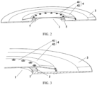
FIG. 2 is a structural view of part of the structure of a ventilation and heat dissipation apparatus of a wind-assisted rotor according to embodiment one of the present application. -
FIG. 3 is a partial enlarged view of the ventilation and heat dissipation apparatus of the wind-assisted rotor inFIG. 2 . -
FIG. 4 is a schematic view of thermal gas flow inside a cylinder according to embodiment one of the present application. -
FIG. 5 is a structural view of part of the structure of a ventilation and heat dissipation apparatus of a wind-assisted rotor according to embodiment two of the present application. -
FIG. 6 is a partial enlarged view of the ventilation and heat dissipation apparatus of the wind-assisted rotor inFIG. 5 . -
FIG. 7 is a structural view of a reinforcement assembly according to embodiment two of the present application. -
- 1
- manhole
- 2
- cylinder
- 3
- top cover
- 4
- rain shielding plate
- 41
- first rain shielding plate
- 42
- second rain shielding plate
- 5
- support column
- 6
- reinforcement assembly
- 61
- lining plate
- 611
- first lining plate
- 612
- second lining plate
- 62
- reinforcement rib
- 7
- rain blocking boss
- 8
- exhaust fan
- In the description of the present application, terms "joined", "connected", and "secured" are to be construed in a broad sense unless otherwise expressly specified and limited. For example, the term "connected" may refer to "securely connected", "detachably connected", or "integrated", may refer to "mechanically connected" or "electrically connected", may refer to "connected directly" or "connected indirectly through an intermediary", or may refer to "connected inside two components" or "an interaction relation between two components". For those of ordinary skill in the art, specific meanings of the preceding terms in the present application may be understood based on specific situations.
- In the present application, unless otherwise expressly specified and limited, when a first feature is described as "above" or "below" a second feature, the first feature and the second feature may be in direct contact or be in contact via another feature between the two features instead of being in direct contact. Moreover, when the first feature is described as "on", "above", or "over" the second feature, the first feature is right on, above, or over the second feature or the first feature is obliquely on, above, or over the second feature, or the first feature is simply at a higher level than the second feature. When the first feature is described as "under", "below", or "underneath" the second feature, the first feature is right under, below, or underneath the second feature or the first feature is obliquely under, below, or underneath the second feature, or the first feature is simply at a lower level than the second feature.
- In the description of embodiments, orientations or position relations indicated by terms such as "upper", "lower", "left", and "right" are based on the drawings. These orientations or position relations are intended only to facilitate description and simplify an operation and not to indicate or imply that a device or element referred to must have such particular orientations or must be configured or operated in such particular orientations. Thus, these orientations or position relations are not to be construed as limiting the present application. In addition, terms "first" and "second" are used only to distinguish between descriptions and have no special meanings.
- As shown in
FIG. 1 , the present embodiment provides a ventilation and heat dissipation apparatus of a wind-assisted rotor, which includes acylinder 2, atop cover 3, and arain shielding plate 4. As shown inFIGS. 2 and 3 , thetop cover 3 is disposed at the top of thecylinder 2 and covers the top of thecylinder 2, thetop cover 3 is provided with amanhole 1, and themanhole 1 communicates with an inner cavity of thecylinder 2. Therain shielding plate 4 is disposed above themanhole 1 and covers themanhole 1, and therain shielding plate 4 and thetop cover 3 are spaced apart to form a heat dissipation gap that communicates with the external atmosphere. As shown inFIG. 4 , the ventilation and heat dissipation apparatus of the wind-assisted rotor according to the present embodiment dissipates heat inside thecylinder 2 to the external atmosphere through the heat dissipation gap between therain shielding plate 4 and thetop cover 3 under the action of anexhaust fan 8. In case of rain and snow, therain shielding plate 4 can prevent rain and snow from entering inside thecylinder 2, thus preventing an electric motor or other components in thecylinder 2 from being damaged by the rain and snow. - In one embodiment,
multiple support columns 5 are used for supporting therain shielding plate 4 above themanhole 1. Thesupport columns 5 are detachably connected between therain shielding plate 4 and thetop cover 3. For example, themultiple support columns 5 are disposed at intervals in the circumferential direction of thetop cover 3. With this structure, themultiple support columns 5 divide the heat dissipation gap into multiple sub-gaps, and the heat inside thecylinder 2 is dissipated to the external atmosphere through a sub-gap between twoadjacent support columns 5. Optionally, themultiple support columns 5 are uniformly disposed between therain shielding plate 4 and thetop cover 3. In one aspect, the connection stability between therain shielding plate 4 and thetop cover 3 can be improved so that therain shielding plate 4 can be stably and horizontally disposed above themanhole 1. In another aspect, themultiple support columns 5 are uniformly disposed so that the multiple sub-gaps have the same size, thereby achieving more uniform heat dissipation. In the present embodiment, thesupport columns 5 are fastened between therain shielding plate 4 and thetop cover 3 through bolts. In one aspect, when a component inside thecylinder 2 is damaged, maintenance personnel can quickly detach therain shielding plate 4 and enter inside thecylinder 2 through themanhole 1 to perform maintenance. In another aspect, if therain shielding plate 4 is eroded or damaged, the maintenance personnel can replace therain shielding plate 4 in time. Optionally, to ensure that thesupport columns 5 can support therain shielding plate 4 stably and improve the connection stability between therain shielding plate 4 and thetop cover 3, in the present embodiment, the number ofsupport columns 5 is 16. In other embodiments, the number ofsupport columns 5 may be designed according to actual conditions. - In one embodiment, the
rain shielding plate 4 includes a firstrain shielding plate 41 and a secondrain shielding plate 42. The firstrain shielding plate 41 is a circular plate disposed directly above themanhole 1. To increase a rain shielding area, the secondrain shielding plate 42 is configured to be an annular slanted plate. A first end of the secondrain shielding plate 42 is connected to the firstrain shielding plate 41 at a first preset angle, and a second end of the secondrain shielding plate 42 is slanted downward towards thetop cover 3. With this structure, a certain heat dissipation gap still exists between the secondrain shielding plate 42 and thetop cover 3 in case that the heat inside thecylinder 2 cannot be dissipated to the external atmosphere in time. To increase the wind resistance strength of therain shielding plate 4, optionally, in the present embodiment, the firstrain shielding plate 41 and the secondrain shielding plate 42 are integrally formed. - To prevent rainwater falling on the
top cover 3 from flowing inside thecylinder 2 through themanhole 1, arain blocking boss 7 is disposed on an inner rim of thetop cover 3 corresponding to themanhole 1. Optionally, therain blocking boss 7 is annular. - To prolong the service life of the ventilation and heat dissipation apparatus of the wind-assisted rotor in the present embodiment, a sunscreen and waterproof layer is coated on both a surface of the
top cover 3 and a surface of therain shielding plate 4. - In one embodiment, an insect screen is disposed between the
rain shielding plate 4 and thetop cover 3 so that foreign matters such as insects are prevented from falling inside thecylinder 2. - According to the ventilation and heat dissipation apparatus of the wind-assisted rotor in the present embodiment, the
rain shielding plate 4 is disposed above themanhole 1 of thetop cover 3 and covers themanhole 1, and therain shielding plate 4 and thetop cover 3 are spaced apart to form the heat dissipation gap that communicates with the external atmosphere so that the heat inside thecylinder 2 can be dissipated to the external atmosphere through the heat dissipation gap, and rain and snow can be prevented from entering inside thecylinder 2. The ventilation and heat dissipation apparatus of the wind-assisted rotor has a simple structure, a good ventilation and heat dissipation effect, and a low production cost and is suitable for practical applications. - The present embodiment provides a ventilation and heat dissipation apparatus of a wind-assisted rotor. As shown in
FIGS. 5 and6 , the ventilation and heat dissipation apparatus of the wind-assisted rotor differs from the ventilation and heat dissipation apparatus of the wind-assisted rotor in embodiment one only in that the ventilation and heat dissipation apparatus of the wind-assisted rotor in the present embodiment has areinforcement assembly 6. - To further enhance the structural strength of the
rain shielding plate 4 to cope with severe weather, the ventilation and heat dissipation apparatus of the wind-assisted rotor in the present embodiment may also include thereinforcement assembly 6. As shown inFIGS. 5 and6 , thereinforcement assembly 6 is disposed on the lower surface of therain shielding plate 4 and disposed between therain shielding plate 4 and thetop cover 3. As shown inFIG. 7 , thereinforcement assembly 6 includes alining plate 61 andreinforcement ribs 62. Thelining plate 61 is disposed between therain shielding plate 4 and thetop cover 3 so that the structural strength of therain shielding plate 4 is enhanced and therain shielding plate 4 assists in blocking rain and snow from entering inside thecylinder 2. A first end of areinforcement rib 62 is fixedly connected to the lower surface of therain shielding plate 4, and a second end of thereinforcement rib 62 is fixedly connected to the upper surface of thelining plate 61, thereby enhancing the connection strength between therain shielding plate 4 and thelining plate 61. - Optionally, the
reinforcement ribs 62 are connected to therain shielding plate 4 and thelining plate 61 by welding. Optionally, to improve the structural strength of therain shielding plate 4 and ensure that heat inside thecylinder 2 can be smoothly dissipated to the external atmosphere, the number ofreinforcement ribs 62 is the same as the number ofsupport columns 5, and thereinforcement ribs 62 and thesupport columns 5 are alternately disposed. - In one embodiment, as shown in
FIG. 7 , thelining plate 61 includes afirst lining plate 611 and a second lining plate 612 which are connected at a second preset angle. Optionally, thefirst lining plate 611 is an annular plate and is disposed on the inner side of the second lining plate 612. The second lining plate 612 is an annular slanted plate, and an end of the second lining plate 612 facing away from thefirst lining plate 611 is slanted downward towards thetop cover 3. In the present embodiment, the first preset angle is the same as the second preset angle so that thelining plate 61 has a relative good effect of assisting therain shielding plate 4 in blocking rain and causes the heat inside thecylinder 2 to flow more smoothly to the external atmosphere, thereby improving heat dissipation efficiency. - To prevent stress concentration at a connection of the
reinforcement rib 62 from damaging therain shielding plate 4 or thelining plate 61,multiple reinforcement ribs 62 are provided, and themultiple reinforcement ribs 62 are uniformly disposed along the circumferential direction of thefirst lining plate 611. In this manner, the uniformity of connection forces is improved, and it is convenient to dissipate the heat inside thecylinder 2 to the external atmosphere through heat dissipation gaps between thesupport columns 5 and thereinforcement ribs 62. - To increase the wind resistance strength of the ventilation and heat dissipation apparatus of the wind-assisted rotor in the present embodiment, optionally, the
first lining plate 611 and second lining plate 612 are integrally formed. - According to the ventilation and heat dissipation apparatus of the wind-assisted rotor in the present embodiment, the
rain shielding plate 4 is disposed above themanhole 1 of thetop cover 3 and covers themanhole 1, and therain shielding plate 4 and thetop cover 3 are spaced apart to form the heat dissipation gap that communicates with the external atmosphere so that the heat inside thecylinder 2 can be dissipated to the external atmosphere through the heat dissipation gap, and rain and snow can be prevented from entering inside thecylinder 2. Thereinforcement assembly 6 is added so that the structural strength of the ventilation and heat dissipation apparatus is enhanced, and the effect of preventing rain and snow can be further enhanced. The ventilation and heat dissipation apparatus of the wind-assisted rotor has a simple structure, a good ventilation and heat dissipation effect, and a low production cost and is suitable for practical applications.
Claims (10)
- A ventilation and heat dissipation apparatus of a wind-assisted rotor, comprising:a cylinder (2);a top cover (3) disposed at a top of the cylinder (2) and covering the top of the cylinder (2), wherein the top cover (3) is provided with a manhole (1) communicating with an inner cavity of the cylinder (2); anda rain shielding plate (4) disposed above the manhole (1) and covering the manhole (1), wherein the rain shielding plate (4) and the top cover (3) are spaced apart to form a heat dissipation gap that communicates with an external atmosphere.
- The ventilation and heat dissipation apparatus of the wind-assisted rotor according to claim 1, further comprising:
a plurality of support columns (5), wherein the plurality of support columns (5) are detachably connected between the rain shielding plate (4) and the top cover (3), and the plurality of support columns (5) are disposed at intervals in a circumferential direction of the top cover (3). - The ventilation and heat dissipation apparatus of the wind-assisted rotor according to claim 2, wherein the plurality of support columns (5) are uniformly disposed between the rain shielding plate (4) and the top cover (3).
- The ventilation and heat dissipation apparatus of the wind-assisted rotor according to claim 2, wherein the plurality of support columns (5) are fastened between the rain shielding plate (4) and the top cover (3) through bolts.
- The ventilation and heat dissipation apparatus of the wind-assisted rotor according to claim 1, wherein the rain shielding plate (4) comprises:a first rain shielding plate (41) disposed directly above the manhole (1); anda second rain shielding plate (42), which is an annular slanted plate, wherein a first end of the second rain shielding plate (42) is connected to the first rain shielding plate (41) at a first preset angle, and a second end of the second rain shielding plate (42) is slanted downward towards the top cover (3).
- The ventilation and heat dissipation apparatus of the wind-assisted rotor according to claim 1, further comprising a reinforcement assembly (6), wherein the reinforcement assembly (6) is connected to a lower surface of the rain shielding plate (4), and the reinforcement assembly (6) and the rain shielding plate (4) are spaced apart to form a heat dissipation gap.
- The ventilation and heat dissipation apparatus of the wind-assisted rotor according to claim 6, wherein the reinforcement assembly (6) comprises:a lining plate (61) disposed between the rain shielding plate (4) and the top cover (3); andreinforcement ribs (62), wherein a first end of each of the reinforcement ribs (62) is fixedly connected to the lower surface of the rain shielding plate (4), and a second end of the each of the reinforcement ribs 62 is fixedly connected to an upper surface of the lining plate (61).
- The ventilation and heat dissipation apparatus of the wind-assisted rotor according to claim 7, wherein the lining plate (61) comprises a first lining plate (611) and a second lining plate (612) which are connected at a second preset angle, whereinthe first lining plate (611) is an annular plate and is disposed on an inner side of the second lining plate (612), andthe second lining plate (612) is an annular slanted plate, and an end of the second lining plate (612) facing away from the first lining plate (611) is slanted downward towards the top cover (3).
- The ventilation and heat dissipation apparatus of the wind-assisted rotor according to claim 8, wherein a plurality of reinforcement ribs (62) are provided, and the plurality of reinforcement ribs (62) are uniformly disposed along a circumferential direction of the first lining plate (611).
- The ventilation and heat dissipation apparatus of the wind-assisted rotor according to any one of claims 1 to 9, wherein a rain blocking boss (7) is disposed on an inner rim of the top cover (3) corresponding to the manhole (1), and the rain blocking boss (7) is annular and configured to prevent outside rainwater from flowing inside the cylinder (2).
Applications Claiming Priority (2)
| Application Number | Priority Date | Filing Date | Title |
|---|---|---|---|
| CN202011310324.7A CN112312748B (en) | 2020-11-20 | 2020-11-20 | A wind-assisted rotor ventilation and heat dissipation device |
| PCT/CN2021/080440 WO2022105077A1 (en) | 2020-11-20 | 2021-03-12 | Ventilation and heat dissipation apparatus of wind power boosting rotor |
Publications (4)
| Publication Number | Publication Date |
|---|---|
| EP4250886A1 true EP4250886A1 (en) | 2023-09-27 |
| EP4250886A4 EP4250886A4 (en) | 2024-10-16 |
| EP4250886B1 EP4250886B1 (en) | 2025-12-31 |
| EP4250886C0 EP4250886C0 (en) | 2025-12-31 |
Family
ID=74335200
Family Applications (1)
| Application Number | Title | Priority Date | Filing Date |
|---|---|---|---|
| EP21893235.8A Active EP4250886B1 (en) | 2020-11-20 | 2021-03-12 | VENTILATION AND HEAT DISPENSING DEVICE |
Country Status (6)
| Country | Link |
|---|---|
| US (1) | US12601363B2 (en) |
| EP (1) | EP4250886B1 (en) |
| JP (1) | JP7570147B2 (en) |
| KR (1) | KR102799505B1 (en) |
| CN (1) | CN112312748B (en) |
| WO (1) | WO2022105077A1 (en) |
Families Citing this family (1)
| Publication number | Priority date | Publication date | Assignee | Title |
|---|---|---|---|---|
| CN112312748B (en) * | 2020-11-20 | 2025-03-04 | 中船(上海)节能技术有限公司 | A wind-assisted rotor ventilation and heat dissipation device |
Family Cites Families (28)
| Publication number | Priority date | Publication date | Assignee | Title |
|---|---|---|---|---|
| US2830526A (en) * | 1954-06-14 | 1958-04-15 | G C Breidert Co | Ventilating device |
| US2987983A (en) * | 1958-10-28 | 1961-06-13 | Isel I Solzman | Plastic casing for air exhauster |
| US2933036A (en) * | 1958-11-03 | 1960-04-19 | G C Breidert Co | Ventilating device |
| US2962118A (en) * | 1958-12-23 | 1960-11-29 | Black & Decker Mfg Co | Electric vacuum cleaner |
| US3211079A (en) * | 1964-06-25 | 1965-10-12 | Richard E Carlson | Vent cap for gas heating structure |
| JPS5863869U (en) | 1981-10-21 | 1983-04-28 | 株式会社日立製作所 | Drip-proof rotating electric machine |
| JP2956336B2 (en) * | 1992-01-09 | 1999-10-04 | 富士電機株式会社 | Waterproof cover for vertical outdoor fully enclosed fan-type rotating electric machine |
| KR20000004567U (en) * | 1998-08-11 | 2000-03-06 | 박태업 | Fixed ventilation |
| JP2004301094A (en) * | 2003-03-31 | 2004-10-28 | Ebara Corp | Wind power generator |
| KR20060000086U (en) * | 2006-11-14 | 2006-12-05 | 박태업 | Fixed ventilation |
| DE112007003687A5 (en) | 2007-08-10 | 2010-07-22 | Krauss, Gunter | Flow energy plant, in particular wind turbine |
| JP5142062B2 (en) * | 2008-02-27 | 2013-02-13 | 株式会社ヨネキン | Building ventilation tower |
| TW201009272A (en) * | 2008-08-18 | 2010-03-01 | Daizu Ind Co Ltd | Natural ventilation equipment with flow-guiding and exhausting functions |
| KR101447658B1 (en) | 2013-03-18 | 2014-10-08 | 이행건 | No Power Fixed type Ventilator for Improving Ventilation Performance |
| GB2514867B (en) * | 2013-11-17 | 2015-08-05 | Norsepower Oy | Propulsion systems for aquatic vessels |
| CN207118139U (en) * | 2017-08-03 | 2018-03-16 | 广东美的暖通设备有限公司 | Controlled box assembly and there is its air conditioner |
| CN108736328A (en) * | 2018-06-27 | 2018-11-02 | 河南森源电气股份有限公司 | One plants case becomes head cover and box-type substation |
| CN208997002U (en) * | 2018-10-30 | 2019-06-18 | 浙江风神风机制造有限公司 | A kind of roof ventilator for opening top cover |
| CN208986460U (en) | 2018-12-08 | 2019-06-14 | 滕州市智星电力电子工程有限公司 | A kind of top cover ventilation and heat structure of box-type substation |
| CN209282615U (en) * | 2019-03-04 | 2019-08-20 | 衢州万电电气有限公司 | An outdoor electrical switchgear with a rainproof and moistureproof structure |
| KR102159714B1 (en) | 2019-05-09 | 2020-09-24 | 이행건 | No Power Fixed type Ventilator for Improving Ventilation Performance |
| CN209675806U (en) * | 2019-06-03 | 2019-11-22 | 河北占顺电力设备有限公司 | A kind of box-type substation with radiator |
| CN210111658U (en) * | 2019-08-07 | 2020-02-21 | 大连德泰机械制造有限公司 | Charging cabinet capable of dissipating heat quickly |
| CN110880705A (en) * | 2019-12-09 | 2020-03-13 | 山东电工电气集团智能电气有限公司 | Heat dissipation top cap, transformer substation box and box-type transformer substation |
| CN111786288A (en) | 2020-07-03 | 2020-10-16 | 合肥乐祎电气有限公司 | Ammeter case with waterproof function dispels heat |
| CN111846175A (en) | 2020-08-18 | 2020-10-30 | 中船重工(上海)节能技术发展有限公司 | A multi-stage wind-assisted rotor device and a ship |
| CN112312748B (en) | 2020-11-20 | 2025-03-04 | 中船(上海)节能技术有限公司 | A wind-assisted rotor ventilation and heat dissipation device |
| CN213522883U (en) * | 2020-11-20 | 2021-06-22 | 中船重工(上海)节能技术发展有限公司 | Wind-force boosting rotor ventilation heat abstractor |
-
2020
- 2020-11-20 CN CN202011310324.7A patent/CN112312748B/en active Active
-
2021
- 2021-03-12 WO PCT/CN2021/080440 patent/WO2022105077A1/en not_active Ceased
- 2021-03-12 US US18/037,947 patent/US12601363B2/en active Active
- 2021-03-12 EP EP21893235.8A patent/EP4250886B1/en active Active
- 2021-03-12 KR KR1020237019794A patent/KR102799505B1/en active Active
- 2021-03-12 JP JP2023530774A patent/JP7570147B2/en active Active
Also Published As
| Publication number | Publication date |
|---|---|
| EP4250886A4 (en) | 2024-10-16 |
| KR102799505B1 (en) | 2025-04-23 |
| EP4250886B1 (en) | 2025-12-31 |
| JP7570147B2 (en) | 2024-10-21 |
| CN112312748B (en) | 2025-03-04 |
| KR20230106674A (en) | 2023-07-13 |
| WO2022105077A1 (en) | 2022-05-27 |
| JP2023549960A (en) | 2023-11-29 |
| EP4250886C0 (en) | 2025-12-31 |
| US20230407874A1 (en) | 2023-12-21 |
| US12601363B2 (en) | 2026-04-14 |
| CN112312748A (en) | 2021-02-02 |
Similar Documents
| Publication | Publication Date | Title |
|---|---|---|
| AU2002256732B2 (en) | Cooling device for a wind turbine generator | |
| CN101064453B (en) | Vehicle alternator | |
| JP4072808B2 (en) | Fluid machinery performance adjustment device | |
| MXPA97005853A (en) | Motors for te fans | |
| US7387496B2 (en) | Fan assembly and impeller thereof | |
| US12601363B2 (en) | Ventilation and heat dissipation apparatus of wind-assisted rotor | |
| EP3754203B1 (en) | Vacuum pump and vacuum pump control device | |
| US8176854B2 (en) | Roof structure for a locomotive power module | |
| CA2752979C (en) | Generator for an electrical machine | |
| CN114944731B (en) | Motor and flight equipment | |
| CN213522883U (en) | Wind-force boosting rotor ventilation heat abstractor | |
| CN209787021U (en) | Centrifugal air-cooled permanent magnet speed regulator | |
| CN217681974U (en) | Aluminum alloy intermediate of turbocharger | |
| US10132497B2 (en) | Generator with vent extension | |
| CN212258638U (en) | Unmanned aerial vehicle and driving motor thereof | |
| CN218449844U (en) | Frequency converter heat dissipation device capable of preventing rainwater from flowing backwards | |
| US7633196B2 (en) | Vehicle-use alternator | |
| US20130264025A1 (en) | Vehicle cooling module fan motor assembly water diverter | |
| CN112103795A (en) | Switch board with heat dissipation function | |
| CN219327674U (en) | Radiator fan that pivot upper bearing was used | |
| CN224037177U (en) | An outdoor heat dissipation, breathability, and rainproof device | |
| JP2021175308A (en) | Power converter | |
| CN223104707U (en) | A compact and efficient rain remover | |
| CN202475146U (en) | Three-phase asynchronous motor cooling system | |
| CN218703929U (en) | Oil moves unmanned aerial vehicle low temperature flight water cooling heat abstractor |
Legal Events
| Date | Code | Title | Description |
|---|---|---|---|
| STAA | Information on the status of an ep patent application or granted ep patent |
Free format text: STATUS: THE INTERNATIONAL PUBLICATION HAS BEEN MADE |
|
| PUAI | Public reference made under article 153(3) epc to a published international application that has entered the european phase |
Free format text: ORIGINAL CODE: 0009012 |
|
| STAA | Information on the status of an ep patent application or granted ep patent |
Free format text: STATUS: REQUEST FOR EXAMINATION WAS MADE |
|
| 17P | Request for examination filed |
Effective date: 20230530 |
|
| AK | Designated contracting states |
Kind code of ref document: A1 Designated state(s): AL AT BE BG CH CY CZ DE DK EE ES FI FR GB GR HR HU IE IS IT LI LT LU LV MC MK MT NL NO PL PT RO RS SE SI SK SM TR |
|
| DAV | Request for validation of the european patent (deleted) | ||
| DAX | Request for extension of the european patent (deleted) | ||
| REG | Reference to a national code |
Ref legal event code: R079 Free format text: PREVIOUS MAIN CLASS: H05K0007200000 Ref country code: DE Ref legal event code: R079 Ref document number: 602021045735 Country of ref document: DE Free format text: PREVIOUS MAIN CLASS: H05K0007200000 Ipc: F03D0003000000 |
|
| A4 | Supplementary search report drawn up and despatched |
Effective date: 20240917 |
|
| RIC1 | Information provided on ipc code assigned before grant |
Ipc: F04D 29/60 20060101ALI20240911BHEP Ipc: F04D 25/08 20060101ALI20240911BHEP Ipc: B63H 9/02 20060101ALI20240911BHEP Ipc: F03D 80/60 20160101ALI20240911BHEP Ipc: F03D 9/32 20160101ALI20240911BHEP Ipc: F03D 3/00 20060101AFI20240911BHEP |
|
| GRAP | Despatch of communication of intention to grant a patent |
Free format text: ORIGINAL CODE: EPIDOSNIGR1 |
|
| STAA | Information on the status of an ep patent application or granted ep patent |
Free format text: STATUS: GRANT OF PATENT IS INTENDED |
|
| INTG | Intention to grant announced |
Effective date: 20250902 |
|
| GRAS | Grant fee paid |
Free format text: ORIGINAL CODE: EPIDOSNIGR3 |
|
| GRAA | (expected) grant |
Free format text: ORIGINAL CODE: 0009210 |
|
| STAA | Information on the status of an ep patent application or granted ep patent |
Free format text: STATUS: THE PATENT HAS BEEN GRANTED |
|
| AK | Designated contracting states |
Kind code of ref document: B1 Designated state(s): AL AT BE BG CH CY CZ DE DK EE ES FI FR GB GR HR HU IE IS IT LI LT LU LV MC MK MT NL NO PL PT RO RS SE SI SK SM TR |
|
| REG | Reference to a national code |
Ref country code: CH Ref legal event code: F10 Free format text: ST27 STATUS EVENT CODE: U-0-0-F10-F00 (AS PROVIDED BY THE NATIONAL OFFICE) Effective date: 20251231 Ref country code: GB Ref legal event code: FG4D |
|
| REG | Reference to a national code |
Ref country code: DE Ref legal event code: R096 Ref document number: 602021045735 Country of ref document: DE |
|
| REG | Reference to a national code |
Ref country code: IE Ref legal event code: FG4D |
|
| U01 | Request for unitary effect filed |
Effective date: 20260127 |
|
| U07 | Unitary effect registered |
Designated state(s): AT BE BG DE DK EE FI FR IT LT LU LV MT NL PT RO SE SI Effective date: 20260130 |
|
| PGFP | Annual fee paid to national office [announced via postgrant information from national office to epo] |
Ref country code: GB Payment date: 20260324 Year of fee payment: 6 |
|
| PG25 | Lapsed in a contracting state [announced via postgrant information from national office to epo] |
Ref country code: NO Free format text: LAPSE BECAUSE OF FAILURE TO SUBMIT A TRANSLATION OF THE DESCRIPTION OR TO PAY THE FEE WITHIN THE PRESCRIBED TIME-LIMIT Effective date: 20260331 |
|
| PG25 | Lapsed in a contracting state [announced via postgrant information from national office to epo] |
Ref country code: HR Free format text: LAPSE BECAUSE OF FAILURE TO SUBMIT A TRANSLATION OF THE DESCRIPTION OR TO PAY THE FEE WITHIN THE PRESCRIBED TIME-LIMIT Effective date: 20251231 |
|
| PG25 | Lapsed in a contracting state [announced via postgrant information from national office to epo] |
Ref country code: RS Free format text: LAPSE BECAUSE OF FAILURE TO SUBMIT A TRANSLATION OF THE DESCRIPTION OR TO PAY THE FEE WITHIN THE PRESCRIBED TIME-LIMIT Effective date: 20260331 |
|
| U20 | Renewal fee for the european patent with unitary effect paid |
Year of fee payment: 6 Effective date: 20260326 |