EP4250492A1 - Electrical connection assembly and connector - Google Patents
Electrical connection assembly and connector Download PDFInfo
- Publication number
- EP4250492A1 EP4250492A1 EP23163711.7A EP23163711A EP4250492A1 EP 4250492 A1 EP4250492 A1 EP 4250492A1 EP 23163711 A EP23163711 A EP 23163711A EP 4250492 A1 EP4250492 A1 EP 4250492A1
- Authority
- EP
- European Patent Office
- Prior art keywords
- connection
- flat conductor
- electrical connection
- pair
- connection terminal
- Prior art date
- Legal status (The legal status is an assumption and is not a legal conclusion. Google has not performed a legal analysis and makes no representation as to the accuracy of the status listed.)
- Pending
Links
Images







Classifications
-
- H—ELECTRICITY
- H01—ELECTRIC ELEMENTS
- H01R—ELECTRICALLY-CONDUCTIVE CONNECTIONS; STRUCTURAL ASSOCIATIONS OF A PLURALITY OF MUTUALLY-INSULATED ELECTRICAL CONNECTING ELEMENTS; COUPLING DEVICES; CURRENT COLLECTORS
- H01R4/00—Electrically-conductive connections between two or more conductive members in direct contact, i.e. touching one another; Means for effecting or maintaining such contact; Electrically-conductive connections having two or more spaced connecting locations for conductors and using contact members penetrating insulation
- H01R4/02—Soldered or welded connections
- H01R4/029—Welded connections
-
- H—ELECTRICITY
- H01—ELECTRIC ELEMENTS
- H01R—ELECTRICALLY-CONDUCTIVE CONNECTIONS; STRUCTURAL ASSOCIATIONS OF A PLURALITY OF MUTUALLY-INSULATED ELECTRICAL CONNECTING ELEMENTS; COUPLING DEVICES; CURRENT COLLECTORS
- H01R11/00—Individual connecting elements providing two or more spaced connecting locations for conductive members which are, or may be, thereby interconnected, e.g. end pieces for wires or cables supported by the wire or cable and having means for facilitating electrical connection to some other wire, terminal, or conductive member, blocks of binding posts
- H01R11/01—Individual connecting elements providing two or more spaced connecting locations for conductive members which are, or may be, thereby interconnected, e.g. end pieces for wires or cables supported by the wire or cable and having means for facilitating electrical connection to some other wire, terminal, or conductive member, blocks of binding posts characterised by the form or arrangement of the conductive interconnection between the connecting locations
-
- H—ELECTRICITY
- H01—ELECTRIC ELEMENTS
- H01R—ELECTRICALLY-CONDUCTIVE CONNECTIONS; STRUCTURAL ASSOCIATIONS OF A PLURALITY OF MUTUALLY-INSULATED ELECTRICAL CONNECTING ELEMENTS; COUPLING DEVICES; CURRENT COLLECTORS
- H01R4/00—Electrically-conductive connections between two or more conductive members in direct contact, i.e. touching one another; Means for effecting or maintaining such contact; Electrically-conductive connections having two or more spaced connecting locations for conductors and using contact members penetrating insulation
- H01R4/58—Electrically-conductive connections between two or more conductive members in direct contact, i.e. touching one another; Means for effecting or maintaining such contact; Electrically-conductive connections having two or more spaced connecting locations for conductors and using contact members penetrating insulation characterised by the form or material of the contacting members
-
- H—ELECTRICITY
- H01—ELECTRIC ELEMENTS
- H01R—ELECTRICALLY-CONDUCTIVE CONNECTIONS; STRUCTURAL ASSOCIATIONS OF A PLURALITY OF MUTUALLY-INSULATED ELECTRICAL CONNECTING ELEMENTS; COUPLING DEVICES; CURRENT COLLECTORS
- H01R4/00—Electrically-conductive connections between two or more conductive members in direct contact, i.e. touching one another; Means for effecting or maintaining such contact; Electrically-conductive connections having two or more spaced connecting locations for conductors and using contact members penetrating insulation
- H01R4/70—Insulation of connections
-
- H—ELECTRICITY
- H01—ELECTRIC ELEMENTS
- H01R—ELECTRICALLY-CONDUCTIVE CONNECTIONS; STRUCTURAL ASSOCIATIONS OF A PLURALITY OF MUTUALLY-INSULATED ELECTRICAL CONNECTING ELEMENTS; COUPLING DEVICES; CURRENT COLLECTORS
- H01R13/00—Details of coupling devices of the kinds covered by groups H01R12/70 or H01R24/00 - H01R33/00
- H01R13/40—Securing contact members in or to a base or case; Insulating of contact members
- H01R13/405—Securing in non-demountable manner, e.g. moulding, riveting
-
- H—ELECTRICITY
- H01—ELECTRIC ELEMENTS
- H01R—ELECTRICALLY-CONDUCTIVE CONNECTIONS; STRUCTURAL ASSOCIATIONS OF A PLURALITY OF MUTUALLY-INSULATED ELECTRICAL CONNECTING ELEMENTS; COUPLING DEVICES; CURRENT COLLECTORS
- H01R4/00—Electrically-conductive connections between two or more conductive members in direct contact, i.e. touching one another; Means for effecting or maintaining such contact; Electrically-conductive connections having two or more spaced connecting locations for conductors and using contact members penetrating insulation
- H01R4/70—Insulation of connections
- H01R4/72—Insulation of connections using a heat shrinking insulating sleeve
-
- H—ELECTRICITY
- H02—GENERATION; CONVERSION OR DISTRIBUTION OF ELECTRIC POWER
- H02G—INSTALLATION OF ELECTRIC CABLES OR LINES, OR OF COMBINED OPTICAL AND ELECTRIC CABLES OR LINES
- H02G15/00—Cable fittings
- H02G15/02—Cable terminations
- H02G15/04—Cable-end sealings
- H02G15/043—Cable-end sealings with end caps, e.g. sleeve closed at one end
- H02G15/046—Cable-end sealings with end caps, e.g. sleeve closed at one end with bores or protruding portions allowing passage of cable conductors
Definitions
- the present invention relates to an electrical connection assembly for a connector, an electrical connection component for a connector and a connector including the electrical connection assembly.
- the high-voltage connector usually comprises a housing, a pair of terminals and a pair of flat conductors.
- the pair of terminals are usually installed side by side in the housing.
- the pair of flat conductors are also arranged side by side and electrically connected to the pair of terminals.
- the width of the flat conductor will be limited.
- the width of the flat conductor is usually equal to the width of the terminal, which seriously affects the current-carrying capacity of the flat conductor.
- the present invention has been made to overcome or alleviate at least one aspect of the above mentioned disadvantages.
- an electrical connection assembly for a connector.
- the electrical connection assembly comprises of a pair of flat conductors which are arranged to overlap each other in the thickness direction thereof, wherein the flat conductor comprises a flat conductor core and an insulation layer cladded on the flat conductor core, and the flat conductor core has an electrical connection part exposed from one end of the insulation layer for electrical connection; a pair of connection terminals which are respectively connected to two surfaces facing each other of the electrical connection parts of the pair of flat conductor cores; and a cladding layer which is cladded on the electrical connection part and the connection terminal, so that the connection between the electrical connection part and the connection terminal is sealed in the cladding layer.
- the electrical connection part of the flat conductor core comprises of a connection end which is offset to one side of the width direction of the flat conductor; and a connection base which is connected between the connection end and the body of the flat conductor core.
- connection ends of the pair of flat conductor cores of the pair of flat conductors are spaced with a first spacing in the width direction.
- connection bases of the pair of flat conductor cores of the pair of flat conductors are partially overlapped with each other in the thickness direction.
- connection bases of the pair of flat conductor cores are separated from each other by a second spacing in the thickness direction.
- connection base of the flat conductor core is offset to one side of the thickness direction of the flat conductor, and the connection bases of the pair of flat conductor cores are offset away from each other to increase the second spacing.
- connection base comprises two opposite sides in the width direction, and at least part of at least one side of the connection base extends obliquely with respect to the length direction of the flat conductor, so that the width of at least part of the connection base gradually increases in a direction away from the connection end.
- connection end has a first width
- body of the flat conductor core has a second width
- first width is less than half of the second width
- the width of at least one part of the connection base is changed from the first width to the second width
- connection end comprises two opposite sides in the width direction, and the two opposite sides of the connection end extend along the length direction of the flat conductor.
- each of the connection end and the connection base has two opposite surfaces in the thickness direction, and the two surfaces of the connection end are flush with the two surfaces of the connection base.
- connection ends of the pair of flat conductor cores are separated from each other by a first spacing in the width direction, and the pair of connection terminals are separated from each other in the width direction;
- connection terminal comprises a first part connected to the connection end of the flat conductor core, at least a part of the first parts of the pair of connection terminals are separated in the width direction by a distance equal to the first distance.
- the first part of the connection terminal is also connected to the surface of the connection base of the flat conductor core to increase the electrical connection area between the connection terminal and the electrical connection part of the flat conductor core.
- connection ends of the pair of flat conductor cores are separated from each other by a second spacing in the thickness direction, and the second spacing is greater than the thickness of the connection terminal; the first part of one connection terminal electrically connected to one flat conductor core is separated from the other flat conductor core by a predetermined distance in the thickness direction.
- the first part of the connection terminal is welded, riveted or crimped to the electrical connection part of the flat conductor core.
- connection terminal also includes a second part extending beyond the electrical connection part of the flat conductor core, the second part is used for electrical connection with a mating connection terminal.
- the electrical connection assembly further comprises a pair of connection barrels which are respectively connected to the second parts of the pair of connection terminals.
- the pair of connection barrels are located outside the cladding layer and are used for electrical connection with two mating connection terminals respectively.
- a riveting hole is formed on the second part of the connection terminal, the connection barrel comprises a riveting part riveted to the riveting hole and a convex part protruding from the riveting hole, the top surface of the convex part is used for electrical contact with the mating connection terminal.
- the second part of the connection terminal is offset to one side of the thickness direction of the first part, and the second parts of the pair of connection terminals are offset close to each other.
- the second part of the connection terminal has a first surface and a second surface opposite to each other in the thickness direction; one of the pair of connection barrels is riveted to the first surface of the second part of one connection terminal, and the other is riveted to the second surface of the second part of the other connection terminal.
- the second part of the connection terminal has two opposite surfaces in the thickness direction, the two surfaces of the second part of one connection terminal are flush with the two surfaces of the second part of the other connection terminal; the top surfaces of the convex parts of the pair of connection barrels are located in the same plane perpendicular to the thickness direction.
- connection terminal and the connection barrel are made of copper, and the flat conductor core is made of aluminum.
- connection barrel is integrally formed on the second part of the connection terminal.
- the pair of flat conductors are identical and interchangeable with each other; and/or the pair of connection terminals are identical and interchangeable with each other; and/or the pair of connection barrels are identical and interchangeable with each other.
- the cladding layer is made of elastic material, and a part of the cladding layer is cladded on the insulation layer of the pair of flat conductors; a sealing structure suitable for matching with an inner wall of a connector housing is formed on the outer surface of the part of the cladding layer, the sealing structure is used to seal a gap between the insulation layers of the pair of flat conductors and the inner wall of the connector housing.
- the sealing structure comprises a plurality of annular ribs formed on the outer surface of the part of the cladding layer, and the plurality of annular ribs are separated from each other in the length direction of the flat conductor.
- the cladding layer is an integrated injection molding part formed on the electrical connection part and the connection terminal by inserting injection molding.
- an electrical connection component for a connector.
- the electrical connection component comprises of a flat conductor core; and an insulation layer cladded on the flat conductor core.
- the flat conductor core has a body and an electrical connection part exposed from one end of the insulation layer, the electrical connection part includes a connection base and a connection end, the connection base is connected between the connection end and the body of the flat conductor core, and the connection end is offset to one side of the width direction of the body of the flat conductor core.
- the flat conductor core is a bus bar.
- the flat conductor core is a profile molding part.
- a connector comprising of a housing; and the above electrical connection assembly installed in the housing.
- the pair of flat conductors are arranged to overlap each other in the thickness direction, so the width of the flat conductor can be increased and the current-carrying capacity of the flat conductor can be improved.
- an electrical connection assembly for a connector.
- the electrical connection assembly comprises of a pair of flat conductors which are arranged to overlap each other in the thickness direction thereof, wherein the flat conductor comprises a flat conductor core and an insulation layer cladded on the flat conductor core, and the flat conductor core has an electrical connection part exposed from one end of the insulation layer for electrical connection; a pair of connection terminals which are respectively connected to two surfaces facing each other of the electrical connection parts of the pair of flat conductor cores; and a cladding layer which is cladded on the electrical connection part and the connection terminal, so that the connection between the electrical connection part and the connection terminal is sealed in the cladding layer.
- an electrical connection component for a connector.
- the electrical connection component comprises of a flat conductor core; and an insulation layer cladded on the flat conductor core.
- the flat conductor core has a body and an electrical connection part exposed from one end of the insulation layer, the electrical connection part includes a connection base and a connection end, the connection base is connected between the connection end and the body of the flat conductor core, and the connection end is offset to one side of the width direction of the body of the flat conductor core.
- a connector comprising of a housing; and the above electrical connection assembly installed in the housing.
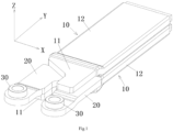
- Figure 1 shows an illustrative perspective view of an electrical connection assembly for a connector according to an exemplary embodiment of the present invention
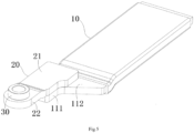
- Figure 2 shows an illustrative exploded view of the electrical connection assembly shown in Figure 1
- Figure 3 shows an illustrative perspective view of a pair of flat conductors 10 of the electrical connection assembly shown in Figure 2 .
- the electrical connection assembly for the connector includes a pair of flat conductors 10.
- the pair of flat conductors 10 are arranged to overlap each other in a thickness direction Z.
- the projections of the pair of flat conductors 10 in the thickness direction Z overlap each other.
- the pair of flat conductors 10 can be stacked up and down. In this way, the width of the flat conductor 10 can be increased to improve the current carrying capacity of the flat conductor 10.
- the flat conductor 10 comprises a flat conductor core 11 and an insulation layer 12 cladded on the flat conductor core 11.
- the flat conductor core 11 has an electrical connection part 110 for electrical connection that is exposed from one end of the insulation layer 12.
- the aforementioned electrical connection part 110 can be formed by cutting and bending the flat conductor core 11 exposed from the insulation layer 12.
- Figure 4 shows an illustrative perspective view of a pair of connection terminals 20 and a pair of connection barrels 30 of the electrical connection assembly shown in Figure 2 ;
- Figure 5 shows the assembly view of a flat conductor 10, a connection terminal 20 and a connection barrel 30 of the electrical connection assembly shown in Figure 1 ;
- Figure 6 shows an illustrative exploded view of a flat conductor 10, a connection terminal 20 and a connection barrel 30 of the electrical connection assembly shown in Figure 1 ;
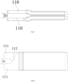
- Figure 7 shows a side view of a pair of flat conductors 10 of the electrical connection assembly shown in Figure 2 ;
- Figure 8 shows a top view of a pair of flat conductors 10 of the electrical connection assembly shown in Figure 2 .
- the electrical connection part 110 of the flat conductor core 11 includes a connection end 111 and a connection base 112.
- the connection end 111 is offset to one side of the width direction X of the flat conductor 10.
- the connection base 112 is connected with the connection end 111 and is located between one end of the insulation layer 12 and the connection end 111.
- the connection base 112 is connected between the connection end 111 and the body 120 of the flat conductor core 11.
- connection ends 111 of the pair of flat conductor cores 11 of the pair of flat conductors 10 are separated from each other by a first spacing D1 in the width direction X.
- connection bases 112 of the pair of flat conductor cores 11 of the pair of flat conductors 10 partially overlap each other in the thickness direction Z. That is to say, the projections of the connection bases 112 of the pair of flat conductor cores 11 in the thickness direction Z partially overlap each other.
- connection bases 112 of the pair of flat conductor cores 11 are separated from each other by a second spacing D2 in the thickness direction Z.
- the connection base 112 of the flat conductor core 11 is offset to one side of the thickness direction Z of the flat conductor 10, and the connection bases 112 of the pair of flat conductor cores 11 are offset away from each other to increase the second spacing D2.
- connection base 112 includes two opposite sides in the width direction X, and at least a part of at least one side 112a of connection base 112 is inclined to extend with respect to the length direction Y of the flat conductor 10, so that the width of at least a part of the connection base 112 gradually increases in a direction away from the connection end 111. That is to say, the width of at least a part of the connection base 112 gradually increases in the direction towards the body 120 of the flat conductor core 11.
- the connection end 111 includes two opposite sides in the width direction X, and the two sides of the connection end 111 extend along the length direction Y of the flat conductor 10.
- the width of the connection end 111 is less than half of the width of the body 120 of the flat conductor core 11.
- the connection end 111 has a first width
- the body 120 of the flat conductor core 11 has a second width
- the width of at least a part of the connection base 112 changes from the first width to the second width.
- the connection end 111 and the connection base 112 are flush with each other in the thickness direction Z.
- connection end 111 in the thickness direction Z are flush with the two opposite surfaces of the connection base 112 in the thickness direction Z. Therefore, in the illustrated embodiment, the spacing of the connection ends 111 of the pair of flat conductor cores 11 in the thickness direction Z is equal to the aforementioned second spacing D2.
- Figure 9 shows a side view of the electrical connection assembly shown in Figure 2 , where only the upper connection terminal 20 is shown;
- Figure 10 shows a side view of the electrical connection assembly shown in Figure 2 , in which only the lower connection terminal 20 is shown;
- Figure 11 shows a side view of the electrical connection assembly shown in Figure 2 .
- the electrical connection assembly also includes a pair of connection terminals 20.
- the connection terminal 20 includes a first part 21.
- the first parts 21 of the pair of connection terminals 20 are respectively connected to two surfaces facing each other of the connection ends 111 of the pair of flat conductor cores 11.
- the pair of connection terminals 20 is separated from each other in the width direction X.
- connection ends 111 of the pair of flat conductor cores 11 are separated from each other by a first spacing D1 in the width direction X, and at least a part of the first parts 21 of the pair of connection terminals 20 are separated by a spacing equal to the first spacing D1 in the width direction X.
- the first part 21 of the connection terminal 20 is also connected to the surface of the connection base 112 of the flat conductor core 11 to increase the electrical connection area between the connection terminal 20 and the electrical connection part 110 of the flat conductor core 11.
- connection ends 111 of the pair of flat conductor cores 11 are separated from each other by a second spacing D2 in the thickness direction Z, and the second spacing D2 is greater than the thickness of the connection terminal 20. Therefore, as shown in Figure 9 and Figure 10 , in the illustrated embodiment, the first part 21 of one connection terminal 20 electrically connected to one flat conductor core 11 is separated from the other flat conductor core 11 by a predetermined spacing D in the thickness direction Z, which is equal to the difference between the second spacing D2 and the thickness of the connection terminal 20.
- the first part 21 of the connection terminal 20 can be welded to the electrical connection part 110 of the flat conductor core 11, for example, it can be welded to the electrical connection part 110 of the flat conductor core 11 by ultrasonic wave.
- the present invention is not limited to the illustrated embodiments.
- the first part 21 of the connection terminal 20 can be riveted, crimped or other suitable ways to be electrically connected to the electrical connection part 110 of the flat conductor core 11.
- connection terminal 20 also includes a second part 22 extending beyond the electrical connection part 110 of the flat conductor core 11 along the length direction of the flat conductor 10, and the second part 22 of the connection terminal 20 is used for electrical connection with a mating connection terminal (not shown).
- the electrical connection assembly also includes a pair of connection barrels 30.
- the pair of connection barrels 30 is respectively connected to the second parts 22 of the pair of connection terminals 20 for electrical connection with two mating connection terminals.
- a riveting hole 221 is formed on the second part 22 of the connection terminal 20.
- the connection barrel 30 includes a riveting part 31 riveted to the riveting hole 221 and a convex part 32 protruding from the riveting hole 221.
- the top surface 32a of the convex part 32 of the connection barrel 30 is used for electrical contact with the mating connection terminal.
- the second part 22 of the connection terminal 20 is offset to one side of the thickness direction Z of the first part 21, and the second parts 22 of the pair of connection terminals 20 are offset close to each other, so that the second parts 22 of the pair of connection terminals 20 is flush with each other in the thickness direction Z. That is, the second part 22 of the connection terminal 20 has two opposite surfaces in the thickness direction Z, the two surfaces of the second part 22 of one connection terminal 20 are flush with the two surfaces of the second part 22 of the other connection terminal 20.
- the second part 22 of the connection terminal 20 has a first surface 20a and a second surface 20b opposite in the thickness direction Z.
- One connection barrel 30 is riveted to the first surface 20a of the second part 22 of one connection terminal 20, and the other connection barrel 30 is riveted to the second surface 20b of the second part 22 of the other connection terminal 20.
- the pair of flat conductors 10 are identical to each other and can be interchangeable with each other.
- the pair of connection terminals 20 are identical to each other and can be interchangeable with each other.
- the pair of connection barrels 30 are identical to each other and can be interchangeable with each other. In this way, the manufacturing cost can be reduced.
- the second parts 22 of the pair of connection terminals 20 are flush with each other in the thickness direction Z. That is to say, the two opposite surfaces of one connection terminal 20 in the thickness direction Z are flush with the two opposite surfaces of the other connection terminal 20 and are perpendicular to the thickness direction Z.
- the top surfaces 32a of the convex parts 32 of the pair of connection barrels 30 are located in the same plane perpendicular to the thickness direction Z.
- connection terminal 20 and the connection barrel 30 are made of copper to improve the conductivity of the connection terminal 20 and the connection barrel 30.
- the flat conductor core 11 is made of aluminum to reduce the manufacturing cost.
- connection barrel 30 can be integrally formed on the second part 22 of the connection terminal 20.
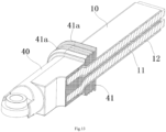
- Figure 12 shows an illustrative perspective view of an electrical connection assembly for a connector according to another exemplary embodiment of the present invention
- Figure 13 shows a longitudinal sectional view of the electrical connection assembly shown in Figure 12 .
- the electrical connection assembly also includes an insulation cladding layer 40.
- the cladding layer 40 is hermetically cladded on the electrical connection part 110 of the flat conductor core 11 and the first part 21 of the connection terminal 20. Apart 41 of the cladding layer 40 is cladded on the insulation layers 12 of the pair of flat conductors 10, and the connection barrel 30 is located outside the cladding layer 40.
- connection between the electrical connection part 110 and the connection terminal 20 is sealed in the cladding layer 40.
- the connection between the electrical connection part 110 and the connection terminal 20 can be isolated from the external environment. Therefore, the connection between the electrical connection part 110 and the connection terminal 20 can be prevented from contacting with water vapor, thereby preventing electrochemical corrosion of the connection between the electrical connection part 110 and the connection terminal 20, and improving the service life of the electrical connection assembly.
- the cladding layer 40 is made of elastic material, for example, the cladding layer 40 can be made of silica gel or any other suitable thermosetting material.
- the cladding layer 40 can be an integral injection molding part formed by inserting injection molding.
- a sealing structure 41a suitable for matching with an inner wall of a connector housing is formed on the outer surface of the part 41 of the cladding layer 40, and the sealing structure 41a is used to seal the gap between the insulation layers 12 of the pair of flat conductors 10 and the inner wall of the connector housing.
- the sealing structure 41a of the cladding layer 40 includes a plurality of annular ribs 41a formed on the outer surface of the part 41 of the cladding layer 40, and the plurality of annular ribs 41a are separated from each other in the length direction of the flat conductor 10.
- Figure 14 shows an illustrative perspective view of an electrical connection assembly for a connector according to another exemplary embodiment of the present invention
- Figure 15 shows an illustrative exploded view of a flat conductor 10 and a connection barrel 30 of the electrical connection assembly shown in Figure 14 .
- connection terminal 20 is removed.
- connection barrels 30 are riveted to the connection ends 111 of the pair of flat conductor cores 11 respectively for electrical connection with two mating connection terminals.
- a riveting hole 101 is formed on the connection end 111 of the flat conductor core 11.
- the connection barrel 30 includes a riveting part 31 riveted to the riveting hole 101 and a convex part 32 protruding from the riveting hole 101.
- the top surface 32a of the convex part 32 (see Fig. 6 ) is used for electrical contact with the mating connection terminal.
- connection end 111 of the flat conductor core 11 is offset to one side of the thickness direction Z of the connection base 112, and the connection ends 111 of the pair of flat conductor cores 11 are offset close to each other, so that the connection ends 111 of the pair of flat conductor cores 11 are flush with each other in the thickness direction Z.
- connection end 111 has a first surface and a second surface opposite in the thickness direction Z.
- One connection barrel 30 in the pair of connection barrels 30 is riveted to the first surface of one connection end 111, and the other connection barrel 30 is riveted to the second surface of the other connection end 111.
- the pair of flat conductors 10 are identical to each other and can be interchangeable with each other.
- the pair of connection barrels 30 are identical to each other and can be interchangeable with each other. In this way, the manufacturing cost can be reduced.
- connection ends 111 of the pair of flat conductor cores 11 are flush with each other in the thickness direction Z. That is to say, the two opposite surfaces of one connection end 111 in the thickness direction Z are flush with the two opposite surfaces of the other connection end 111 and are perpendicular to the thickness direction Z.
- the top surfaces 32a of the convex parts 32 of the pair of connection barrels 30 are located in the same plane perpendicular to the thickness direction Z.
- connection barrel 30 is made of copper to improve the conductivity.
- the flat conductor core 11 is made of aluminum to reduce the manufacturing cost.
- Figure 16 shows a cladding layer 40 formed on one end of the flat conductor 10 of the electrical connection assembly shown in Figure 14 .
- the electrical connection assembly also includes a cladding layer 40, which is sealed on the connection base 112 of the electrical connection part 110 and a part of the connection end 111 of the electrical connection part 110.
- a part 41 of the cladding layer 40 is cladded on the insulation layers 12 of the pair of flat conductors 10, and the connection barrel 30 is located outside the cladding layer 40.
- the cladding layer 40 is made of elastic materials, for example, the cladding layer 40 can be made of silica gel or any other suitable thermosetting material.
- the cladding layer 40 can be an integral injection molding part formed by inserting injection molding.
- a sealing structure 41a suitable for matching with an inner wall of a connector housing is formed on the outer surface of the part 41 of the cladding 40.
- the sealing structure 41a is used to seal the gap between the insulation layers 12 of the pair of flat conductors 10 and the inner wall of the connector housing.
- the sealing structure 41a comprises a plurality of annular ribs 41a formed on the outer surface of the part 41 of the cladding layer 40, and the plurality of annular ribs 41a are spaced from each other in the length direction of the flat conductor 10.
- a connector is also disclosed.
- the connector comprises a housing and the aforementioned electrical connection assembly.
- the electrical connection assembly is installed in the housing.
- an electrical connection component 10 for a connector is also disclosed.
- the electrical connection component 10 includes: a flat conductor core 11; and an insulation layer 12 cladded on the flat conductor core 11.
- the flat conductor core 11 has a body 120 and an electrical connection part 110 exposed from one end of the insulation layer 12.
- the electrical connection part 110 includes a connection base 112 and a connection end 111.
- the connection base 112 is connected between the connection end 111 and the body 120 of the flat conductor core 11, and the connection end 111 is offset to one side of the width direction X of the body 120 of the flat conductor core 11.
- the aforementioned flat conductor core 10 can be a bus bar.
- the aforementioned flat conductor core 10 can be a profiled part, for example, a stamping part.
- the aforementioned electrical connection component 10 can be a flat wire.
Landscapes
- Connections Effected By Soldering, Adhesion, Or Permanent Deformation (AREA)
Abstract
Description
- This application claims the benefit of Chinese Patent Application No.
CN 202220673395.1 filed on March 25, 2022 - The present invention relates to an electrical connection assembly for a connector, an electrical connection component for a connector and a connector including the electrical connection assembly.
- In the prior art, the high-voltage connector usually comprises a housing, a pair of terminals and a pair of flat conductors. The pair of terminals are usually installed side by side in the housing. The pair of flat conductors are also arranged side by side and electrically connected to the pair of terminals. In the prior art, because the pair of flat conductors are arranged side by side, the width of the flat conductor will be limited. The width of the flat conductor is usually equal to the width of the terminal, which seriously affects the current-carrying capacity of the flat conductor.
- The present invention has been made to overcome or alleviate at least one aspect of the above mentioned disadvantages.
- According to an aspect of the present invention, there is provided an electrical connection assembly for a connector. The electrical connection assembly comprises of a pair of flat conductors which are arranged to overlap each other in the thickness direction thereof, wherein the flat conductor comprises a flat conductor core and an insulation layer cladded on the flat conductor core, and the flat conductor core has an electrical connection part exposed from one end of the insulation layer for electrical connection; a pair of connection terminals which are respectively connected to two surfaces facing each other of the electrical connection parts of the pair of flat conductor cores; and a cladding layer which is cladded on the electrical connection part and the connection terminal, so that the connection between the electrical connection part and the connection terminal is sealed in the cladding layer.
- According to an exemplary embodiment of the present invention, the electrical connection part of the flat conductor core comprises of a connection end which is offset to one side of the width direction of the flat conductor; and a connection base which is connected between the connection end and the body of the flat conductor core.
- According to another exemplary embodiment of the present invention, the connection ends of the pair of flat conductor cores of the pair of flat conductors are spaced with a first spacing in the width direction.
- According to another exemplary embodiment of the present invention, the connection bases of the pair of flat conductor cores of the pair of flat conductors are partially overlapped with each other in the thickness direction.
- According to another exemplary embodiment of the present invention, the connection bases of the pair of flat conductor cores are separated from each other by a second spacing in the thickness direction.
- According to another exemplary embodiment of the present invention, the connection base of the flat conductor core is offset to one side of the thickness direction of the flat conductor, and the connection bases of the pair of flat conductor cores are offset away from each other to increase the second spacing.
- According to another exemplary embodiment of the present invention, the connection base comprises two opposite sides in the width direction, and at least part of at least one side of the connection base extends obliquely with respect to the length direction of the flat conductor, so that the width of at least part of the connection base gradually increases in a direction away from the connection end.
- According to another exemplary embodiment of the present invention, the connection end has a first width, the body of the flat conductor core has a second width, and the first width is less than half of the second width; the width of at least one part of the connection base is changed from the first width to the second width.
- According to another exemplary embodiment of the present invention, the connection end comprises two opposite sides in the width direction, and the two opposite sides of the connection end extend along the length direction of the flat conductor.
- According to another exemplary embodiment of the present invention, each of the connection end and the connection base has two opposite surfaces in the thickness direction, and the two surfaces of the connection end are flush with the two surfaces of the connection base.
- According to another exemplary embodiment of the present invention, the connection ends of the pair of flat conductor cores are separated from each other by a first spacing in the width direction, and the pair of connection terminals are separated from each other in the width direction; the connection terminal comprises a first part connected to the connection end of the flat conductor core, at least a part of the first parts of the pair of connection terminals are separated in the width direction by a distance equal to the first distance.
- According to another exemplary embodiment of the present invention, the first part of the connection terminal is also connected to the surface of the connection base of the flat conductor core to increase the electrical connection area between the connection terminal and the electrical connection part of the flat conductor core.
- According to another exemplary embodiment of the present invention, the connection ends of the pair of flat conductor cores are separated from each other by a second spacing in the thickness direction, and the second spacing is greater than the thickness of the connection terminal; the first part of one connection terminal electrically connected to one flat conductor core is separated from the other flat conductor core by a predetermined distance in the thickness direction.
- According to another exemplary embodiment of the present invention, the first part of the connection terminal is welded, riveted or crimped to the electrical connection part of the flat conductor core.
- According to another exemplary embodiment of the present invention, the connection terminal also includes a second part extending beyond the electrical connection part of the flat conductor core, the second part is used for electrical connection with a mating connection terminal.
- According to another exemplary embodiment of the present invention, the electrical connection assembly further comprises a pair of connection barrels which are respectively connected to the second parts of the pair of connection terminals. The pair of connection barrels are located outside the cladding layer and are used for electrical connection with two mating connection terminals respectively.
- According to another exemplary embodiment of the present invention, a riveting hole is formed on the second part of the connection terminal, the connection barrel comprises a riveting part riveted to the riveting hole and a convex part protruding from the riveting hole, the top surface of the convex part is used for electrical contact with the mating connection terminal.
- According to another exemplary embodiment of the present invention, the second part of the connection terminal is offset to one side of the thickness direction of the first part, and the second parts of the pair of connection terminals are offset close to each other.
- According to another exemplary embodiment of the present invention, the second part of the connection terminal has a first surface and a second surface opposite to each other in the thickness direction; one of the pair of connection barrels is riveted to the first surface of the second part of one connection terminal, and the other is riveted to the second surface of the second part of the other connection terminal.
- According to another exemplary embodiment of the present invention, the second part of the connection terminal has two opposite surfaces in the thickness direction, the two surfaces of the second part of one connection terminal are flush with the two surfaces of the second part of the other connection terminal; the top surfaces of the convex parts of the pair of connection barrels are located in the same plane perpendicular to the thickness direction.
- According to another exemplary embodiment of the present invention, the connection terminal and the connection barrel are made of copper, and the flat conductor core is made of aluminum.
- According to another exemplary embodiment of the present invention, the connection barrel is integrally formed on the second part of the connection terminal.
- According to another exemplary embodiment of the present invention, the pair of flat conductors are identical and interchangeable with each other; and/or the pair of connection terminals are identical and interchangeable with each other; and/or the pair of connection barrels are identical and interchangeable with each other.
- According to another exemplary embodiment of the present invention, the cladding layer is made of elastic material, and a part of the cladding layer is cladded on the insulation layer of the pair of flat conductors; a sealing structure suitable for matching with an inner wall of a connector housing is formed on the outer surface of the part of the cladding layer, the sealing structure is used to seal a gap between the insulation layers of the pair of flat conductors and the inner wall of the connector housing.
- According to another exemplary embodiment of the present invention, the sealing structure comprises a plurality of annular ribs formed on the outer surface of the part of the cladding layer, and the plurality of annular ribs are separated from each other in the length direction of the flat conductor.
- According to another exemplary embodiment of the present invention, the cladding layer is an integrated injection molding part formed on the electrical connection part and the connection terminal by inserting injection molding.
- According to another aspect of the present invention, there is provided an electrical connection component for a connector. The electrical connection component comprises of a flat conductor core; and an insulation layer cladded on the flat conductor core. The flat conductor core has a body and an electrical connection part exposed from one end of the insulation layer, the electrical connection part includes a connection base and a connection end, the connection base is connected between the connection end and the body of the flat conductor core, and the connection end is offset to one side of the width direction of the body of the flat conductor core.
- According to an exemplary embodiment of the present invention, the flat conductor core is a bus bar.
- According to another exemplary embodiment of the present invention, the flat conductor core is a profile molding part.
- According to another aspect of the present invention, there is provided a connector. The connector comprises of a housing; and the above electrical connection assembly installed in the housing.
- In the aforementioned exemplary embodiments according to the present invention, the pair of flat conductors are arranged to overlap each other in the thickness direction, so the width of the flat conductor can be increased and the current-carrying capacity of the flat conductor can be improved.
- The above and other features of the present invention will become more apparent by describing in detail exemplary embodiments thereof with reference to the accompanying drawings, in which:
-
Figure 1 shows an illustrative perspective view of an electrical connection assembly for a connector according to an exemplary embodiment of the present invention; -
Figure 2 shows an illustrative exploded view of the electrical connection assembly shown inFigure 1 ; -
Figure 3 shows an illustrative perspective view of a pair of flat conductors of the electrical connection assembly shown inFigure 2 ; -
Figure 4 shows an illustrative perspective view of a pair of connection terminals and a pair of connection barrels of the electrical connection assembly shown inFigure 2 ; -
Figure 5 shows an illustrative assembly view of a flat conductor, a connection terminal and a connection barrel of the electrical connection assembly shown inFigure 1 ; -
Figure 6 shows an illustrative exploded view of a flat conductor, a connection terminal and a connection barrel of the electrical connection assembly shown inFigure 1 ; -
Figure 7 shows a side view of a pair of flat conductors of the electrical connection assembly shown inFigure 2 ; -
Figure 8 shows a top view of a pair of flat conductors of the electrical connection assembly shown inFigure 2 ; -
Figure 9 shows a side view of the electrical connection assembly shown inFigure 2 , where only the upper connection terminal is shown; -
Figure 10 shows a side view of the electrical connection assembly shown inFigure 2 , where only the lower connection terminal is shown; -
Figure 11 shows a side view of the electrical connection assembly shown inFigure 2 ; -
Figure 12 shows an illustrative perspective view of an electrical connection assembly for a connector according to another exemplary embodiment of the present invention; -
Figure 13 shows a longitudinal sectional view of the electrical connection assembly shown inFigure 12 ; -
Figure 14 shows an illustrative perspective view of an electrical connection assembly for a connector according to another exemplary embodiment of the present invention; -
Figure 15 shows an illustrative exploded view of a flat conductor and a connection barrel of the electrical connection assembly shown inFigure 14 ; and -
Figure 16 shows a cladding layer formed on one end of the flat conductor of the electrical connection assembly shown inFigure 14 . - Exemplary embodiments of the present disclosure will be described hereinafter in detail with reference to the attached drawings, wherein the like reference numerals refer to the like elements. The present disclosure may, however, be embodied in many different forms and should not be construed as being limited to the embodiment set forth herein; rather, these embodiments are provided so that the present disclosure will be thorough and complete, and will fully convey the concept of the disclosure to those skilled in the art.
- In the following detailed description, for purposes of explanation, numerous specific details are set forth in order to provide a thorough understanding of the disclosed embodiments. It will be apparent, however, that one or more embodiments may be practiced without these specific details. In other instances, well-known structures and devices are schematically shown in order to simplify the drawing.
- According to a general concept of the present invention, there is provided an electrical connection assembly for a connector. The electrical connection assembly comprises of a pair of flat conductors which are arranged to overlap each other in the thickness direction thereof, wherein the flat conductor comprises a flat conductor core and an insulation layer cladded on the flat conductor core, and the flat conductor core has an electrical connection part exposed from one end of the insulation layer for electrical connection; a pair of connection terminals which are respectively connected to two surfaces facing each other of the electrical connection parts of the pair of flat conductor cores; and a cladding layer which is cladded on the electrical connection part and the connection terminal, so that the connection between the electrical connection part and the connection terminal is sealed in the cladding layer.
- According to another general concept of the present invention, there is provided an electrical connection component for a connector. The electrical connection component comprises of a flat conductor core; and an insulation layer cladded on the flat conductor core. The flat conductor core has a body and an electrical connection part exposed from one end of the insulation layer, the electrical connection part includes a connection base and a connection end, the connection base is connected between the connection end and the body of the flat conductor core, and the connection end is offset to one side of the width direction of the body of the flat conductor core.
- According to another general concept of the present invention, there is provided a connector. The connector comprises of a housing; and the above electrical connection assembly installed in the housing.
-
Figure 1 shows an illustrative perspective view of an electrical connection assembly for a connector according to an exemplary embodiment of the present invention;Figure 2 shows an illustrative exploded view of the electrical connection assembly shown inFigure 1 ;Figure 3 shows an illustrative perspective view of a pair offlat conductors 10 of the electrical connection assembly shown inFigure 2 . - As shown in
Figures 1 to 3 , in the illustrated embodiment, the electrical connection assembly for the connector includes a pair offlat conductors 10. The pair offlat conductors 10 are arranged to overlap each other in a thickness direction Z. In other words, the projections of the pair offlat conductors 10 in the thickness direction Z overlap each other. For example, in an exemplary embodiment of the present invention, the pair offlat conductors 10 can be stacked up and down. In this way, the width of theflat conductor 10 can be increased to improve the current carrying capacity of theflat conductor 10. - As shown in
Figures 1 to 3 , in the illustrated embodiment, theflat conductor 10 comprises aflat conductor core 11 and aninsulation layer 12 cladded on theflat conductor core 11. Theflat conductor core 11 has anelectrical connection part 110 for electrical connection that is exposed from one end of theinsulation layer 12. In an exemplary embodiment of the present invention, for example, the aforementionedelectrical connection part 110 can be formed by cutting and bending theflat conductor core 11 exposed from theinsulation layer 12. -
Figure 4 shows an illustrative perspective view of a pair ofconnection terminals 20 and a pair of connection barrels 30 of the electrical connection assembly shown inFigure 2 ;Figure 5 shows the assembly view of aflat conductor 10, aconnection terminal 20 and aconnection barrel 30 of the electrical connection assembly shown inFigure 1 ;Figure 6 shows an illustrative exploded view of aflat conductor 10, aconnection terminal 20 and aconnection barrel 30 of the electrical connection assembly shown inFigure 1 ;Figure 7 shows a side view of a pair offlat conductors 10 of the electrical connection assembly shown inFigure 2 ;Figure 8 shows a top view of a pair offlat conductors 10 of the electrical connection assembly shown inFigure 2 . - As shown in
Figures 1 to 8 , in the illustrated embodiment, theelectrical connection part 110 of theflat conductor core 11 includes aconnection end 111 and aconnection base 112. Theconnection end 111 is offset to one side of the width direction X of theflat conductor 10. Theconnection base 112 is connected with theconnection end 111 and is located between one end of theinsulation layer 12 and theconnection end 111. Theconnection base 112 is connected between theconnection end 111 and thebody 120 of theflat conductor core 11. - As shown in
Figures 1 to 8 , in the illustrated embodiment, the connection ends 111 of the pair offlat conductor cores 11 of the pair offlat conductors 10 are separated from each other by a first spacing D1 in the width direction X. - As shown in
Figures 1 to 8 , in the illustrated embodiment, the connection bases 112 of the pair offlat conductor cores 11 of the pair offlat conductors 10 partially overlap each other in the thickness direction Z. That is to say, the projections of the connection bases 112 of the pair offlat conductor cores 11 in the thickness direction Z partially overlap each other. - As shown in
Figures 1 to 8 , in the illustrated embodiment, the connection bases 112 of the pair offlat conductor cores 11 are separated from each other by a second spacing D2 in the thickness direction Z. In the illustrated embodiment, theconnection base 112 of theflat conductor core 11 is offset to one side of the thickness direction Z of theflat conductor 10, and the connection bases 112 of the pair offlat conductor cores 11 are offset away from each other to increase the second spacing D2. - As shown in
Figures 1 to 8 , in the illustrated embodiment, theconnection base 112 includes two opposite sides in the width direction X, and at least a part of at least oneside 112a ofconnection base 112 is inclined to extend with respect to the length direction Y of theflat conductor 10, so that the width of at least a part of theconnection base 112 gradually increases in a direction away from theconnection end 111. That is to say, the width of at least a part of theconnection base 112 gradually increases in the direction towards thebody 120 of theflat conductor core 11. - As shown in
Figures 1 to 8 , in the illustrated embodiment, theconnection end 111 includes two opposite sides in the width direction X, and the two sides of theconnection end 111 extend along the length direction Y of theflat conductor 10. In the illustrated embodiment, the width of theconnection end 111 is less than half of the width of thebody 120 of theflat conductor core 11. In the illustrated embodiment, theconnection end 111 has a first width, and thebody 120 of theflat conductor core 11 has a second width, the width of at least a part of theconnection base 112 changes from the first width to the second width. As shown inFigures 1 to 8 , in the illustrated embodiment, theconnection end 111 and theconnection base 112 are flush with each other in the thickness direction Z. In other words, the two opposite surfaces of theconnection end 111 in the thickness direction Z are flush with the two opposite surfaces of theconnection base 112 in the thickness direction Z. Therefore, in the illustrated embodiment, the spacing of the connection ends 111 of the pair offlat conductor cores 11 in the thickness direction Z is equal to the aforementioned second spacing D2. -
Figure 9 shows a side view of the electrical connection assembly shown inFigure 2 , where only theupper connection terminal 20 is shown;Figure 10 shows a side view of the electrical connection assembly shown inFigure 2 , in which only thelower connection terminal 20 is shown;Figure 11 shows a side view of the electrical connection assembly shown inFigure 2 . - As shown in
Figures 1 to 11 , in the illustrated embodiment, the electrical connection assembly also includes a pair ofconnection terminals 20. Theconnection terminal 20 includes afirst part 21. Thefirst parts 21 of the pair ofconnection terminals 20 are respectively connected to two surfaces facing each other of the connection ends 111 of the pair offlat conductor cores 11. The pair ofconnection terminals 20 is separated from each other in the width direction X. - As shown in
Figures 1 to 11 , in the illustrated embodiment, the connection ends 111 of the pair offlat conductor cores 11 are separated from each other by a first spacing D1 in the width direction X, and at least a part of thefirst parts 21 of the pair ofconnection terminals 20 are separated by a spacing equal to the first spacing D1 in the width direction X. - As shown in
Figures 1 to 11 , in the illustrated embodiment, thefirst part 21 of theconnection terminal 20 is also connected to the surface of theconnection base 112 of theflat conductor core 11 to increase the electrical connection area between theconnection terminal 20 and theelectrical connection part 110 of theflat conductor core 11. - As shown in
Figures 1 to 11 , in the illustrated embodiment, the connection ends 111 of the pair offlat conductor cores 11 are separated from each other by a second spacing D2 in the thickness direction Z, and the second spacing D2 is greater than the thickness of theconnection terminal 20. Therefore, as shown inFigure 9 and Figure 10 , in the illustrated embodiment, thefirst part 21 of oneconnection terminal 20 electrically connected to oneflat conductor core 11 is separated from the otherflat conductor core 11 by a predetermined spacing D in the thickness direction Z, which is equal to the difference between the second spacing D2 and the thickness of theconnection terminal 20. - As shown in
Figures 1 to 11 , in the illustrated embodiment, thefirst part 21 of theconnection terminal 20 can be welded to theelectrical connection part 110 of theflat conductor core 11, for example, it can be welded to theelectrical connection part 110 of theflat conductor core 11 by ultrasonic wave. However, please note that the present invention is not limited to the illustrated embodiments. For example, thefirst part 21 of theconnection terminal 20 can be riveted, crimped or other suitable ways to be electrically connected to theelectrical connection part 110 of theflat conductor core 11. - As shown in
Figures 1 to 11 , in the illustrated embodiment, theconnection terminal 20 also includes asecond part 22 extending beyond theelectrical connection part 110 of theflat conductor core 11 along the length direction of theflat conductor 10, and thesecond part 22 of theconnection terminal 20 is used for electrical connection with a mating connection terminal (not shown). - As shown in
Figures 1 to 11 , in the illustrated embodiment, the electrical connection assembly also includes a pair of connection barrels 30. The pair of connection barrels 30 is respectively connected to thesecond parts 22 of the pair ofconnection terminals 20 for electrical connection with two mating connection terminals. - As shown in
Figures 1 to 11 , in the illustrated embodiment, ariveting hole 221 is formed on thesecond part 22 of theconnection terminal 20. Theconnection barrel 30 includes ariveting part 31 riveted to theriveting hole 221 and aconvex part 32 protruding from theriveting hole 221. Thetop surface 32a of theconvex part 32 of theconnection barrel 30 is used for electrical contact with the mating connection terminal. - As shown in
Figures 1 to 11 , in the illustrated embodiment, thesecond part 22 of theconnection terminal 20 is offset to one side of the thickness direction Z of thefirst part 21, and thesecond parts 22 of the pair ofconnection terminals 20 are offset close to each other, so that thesecond parts 22 of the pair ofconnection terminals 20 is flush with each other in the thickness direction Z. that is, thesecond part 22 of theconnection terminal 20 has two opposite surfaces in the thickness direction Z, the two surfaces of thesecond part 22 of oneconnection terminal 20 are flush with the two surfaces of thesecond part 22 of theother connection terminal 20. - As shown in
Figures 1 to 11 , in the illustrated embodiment, thesecond part 22 of theconnection terminal 20 has afirst surface 20a and asecond surface 20b opposite in the thickness direction Z. Oneconnection barrel 30 is riveted to thefirst surface 20a of thesecond part 22 of oneconnection terminal 20, and theother connection barrel 30 is riveted to thesecond surface 20b of thesecond part 22 of theother connection terminal 20. - As shown in
Figures 1 to 11 , in the illustrated embodiment, the pair offlat conductors 10 are identical to each other and can be interchangeable with each other. The pair ofconnection terminals 20 are identical to each other and can be interchangeable with each other. The pair of connection barrels 30 are identical to each other and can be interchangeable with each other. In this way, the manufacturing cost can be reduced. - As shown in
Figures 1 to 11 , in the illustrated embodiment, thesecond parts 22 of the pair ofconnection terminals 20 are flush with each other in the thickness direction Z. That is to say, the two opposite surfaces of oneconnection terminal 20 in the thickness direction Z are flush with the two opposite surfaces of theother connection terminal 20 and are perpendicular to the thickness direction Z. - As shown in
Figures 1 to 11 , in the illustrated embodiment, thetop surfaces 32a of theconvex parts 32 of the pair of connection barrels 30 are located in the same plane perpendicular to the thickness direction Z. - As shown in
Figures 1 to 11 , in the illustrated embodiment, theconnection terminal 20 and theconnection barrel 30 are made of copper to improve the conductivity of theconnection terminal 20 and theconnection barrel 30. Theflat conductor core 11 is made of aluminum to reduce the manufacturing cost. - Although not shown, in an exemplary embodiment of the present invention, the
aforementioned connection barrel 30 can be integrally formed on thesecond part 22 of theconnection terminal 20. -
Figure 12 shows an illustrative perspective view of an electrical connection assembly for a connector according to another exemplary embodiment of the present invention;Figure 13 shows a longitudinal sectional view of the electrical connection assembly shown inFigure 12 . - As shown in
Figures 1 to 13 , in the illustrated embodiment, the electrical connection assembly also includes aninsulation cladding layer 40. Thecladding layer 40 is hermetically cladded on theelectrical connection part 110 of theflat conductor core 11 and thefirst part 21 of theconnection terminal 20. Apart 41 of thecladding layer 40 is cladded on the insulation layers 12 of the pair offlat conductors 10, and theconnection barrel 30 is located outside thecladding layer 40. - As shown in
Figures 1 to 13 , in the illustrated embodiment, the connection between theelectrical connection part 110 and theconnection terminal 20 is sealed in thecladding layer 40. In this way, the connection between theelectrical connection part 110 and theconnection terminal 20 can be isolated from the external environment. Therefore, the connection between theelectrical connection part 110 and theconnection terminal 20 can be prevented from contacting with water vapor, thereby preventing electrochemical corrosion of the connection between theelectrical connection part 110 and theconnection terminal 20, and improving the service life of the electrical connection assembly. - As shown in
Figures 1 to 13 , in the illustrated embodiment, thecladding layer 40 is made of elastic material, for example, thecladding layer 40 can be made of silica gel or any other suitable thermosetting material. Thecladding layer 40 can be an integral injection molding part formed by inserting injection molding. - As shown in
Figures 1 to 13 , in the illustrated embodiment, a sealingstructure 41a suitable for matching with an inner wall of a connector housing (not shown) is formed on the outer surface of thepart 41 of thecladding layer 40, and the sealingstructure 41a is used to seal the gap between the insulation layers 12 of the pair offlat conductors 10 and the inner wall of the connector housing. - As shown in
Figures 1 to 13 , in the illustrated embodiment, the sealingstructure 41a of thecladding layer 40 includes a plurality ofannular ribs 41a formed on the outer surface of thepart 41 of thecladding layer 40, and the plurality ofannular ribs 41a are separated from each other in the length direction of theflat conductor 10. -
Figure 14 shows an illustrative perspective view of an electrical connection assembly for a connector according to another exemplary embodiment of the present invention;Figure 15 shows an illustrative exploded view of aflat conductor 10 and aconnection barrel 30 of the electrical connection assembly shown inFigure 14 . - The main difference between the embodiments shown in
Figures 14 and15 and those shown inFigures 1 to 13 is that theconnection terminal 20 is removed. - As shown in
Figure 14 andFigure 15 , in the illustrated embodiment, a pair of connection barrels 30 are riveted to the connection ends 111 of the pair offlat conductor cores 11 respectively for electrical connection with two mating connection terminals. - As shown in
Figures 14 and15 , in the illustrated embodiment, ariveting hole 101 is formed on theconnection end 111 of theflat conductor core 11. Theconnection barrel 30 includes ariveting part 31 riveted to theriveting hole 101 and aconvex part 32 protruding from theriveting hole 101. Thetop surface 32a of the convex part 32 (seeFig. 6 ) is used for electrical contact with the mating connection terminal. - As shown in
Figure 14 andFigure 15 , in the illustrated embodiment, theconnection end 111 of theflat conductor core 11 is offset to one side of the thickness direction Z of theconnection base 112, and the connection ends 111 of the pair offlat conductor cores 11 are offset close to each other, so that the connection ends 111 of the pair offlat conductor cores 11 are flush with each other in the thickness direction Z. - As shown in
Figures 14 and15 , in the illustrated embodiment, theconnection end 111 has a first surface and a second surface opposite in the thickness direction Z. Oneconnection barrel 30 in the pair of connection barrels 30 is riveted to the first surface of oneconnection end 111, and theother connection barrel 30 is riveted to the second surface of theother connection end 111. - As shown in
Figures 14 and15 , in the illustrated embodiment, the pair offlat conductors 10 are identical to each other and can be interchangeable with each other. The pair of connection barrels 30 are identical to each other and can be interchangeable with each other. In this way, the manufacturing cost can be reduced. - As shown in
Figures 14 and15 , in the illustrated embodiment, the connection ends 111 of the pair offlat conductor cores 11 are flush with each other in the thickness direction Z. That is to say, the two opposite surfaces of oneconnection end 111 in the thickness direction Z are flush with the two opposite surfaces of the other connection end 111 and are perpendicular to the thickness direction Z. The top surfaces 32a of theconvex parts 32 of the pair of connection barrels 30 are located in the same plane perpendicular to the thickness direction Z. - As shown in
Figures 14 and15 , in the illustrated embodiment, theconnection barrel 30 is made of copper to improve the conductivity. Theflat conductor core 11 is made of aluminum to reduce the manufacturing cost. -
Figure 16 shows acladding layer 40 formed on one end of theflat conductor 10 of the electrical connection assembly shown inFigure 14 . - As shown in
Figures 14 to 16 , in the illustrated embodiment, the electrical connection assembly also includes acladding layer 40, which is sealed on theconnection base 112 of theelectrical connection part 110 and a part of theconnection end 111 of theelectrical connection part 110. Apart 41 of thecladding layer 40 is cladded on the insulation layers 12 of the pair offlat conductors 10, and theconnection barrel 30 is located outside thecladding layer 40. - As shown in
Figures 14 to 16 , in the illustrated embodiment, thecladding layer 40 is made of elastic materials, for example, thecladding layer 40 can be made of silica gel or any other suitable thermosetting material. Thecladding layer 40 can be an integral injection molding part formed by inserting injection molding. - As shown in
Figures 14 to 16 , in the illustrated embodiment, a sealingstructure 41a suitable for matching with an inner wall of a connector housing is formed on the outer surface of thepart 41 of thecladding 40. The sealingstructure 41a is used to seal the gap between the insulation layers 12 of the pair offlat conductors 10 and the inner wall of the connector housing. - As shown in
Figures 14 to 16 , in the illustrated embodiment, the sealingstructure 41a comprises a plurality ofannular ribs 41a formed on the outer surface of thepart 41 of thecladding layer 40, and the plurality ofannular ribs 41a are spaced from each other in the length direction of theflat conductor 10. - As shown in
Figures 1 to 16 , in an exemplary embodiment of the present invention, a connector is also disclosed. The connector comprises a housing and the aforementioned electrical connection assembly. The electrical connection assembly is installed in the housing. - As shown in
Figures 1 to 16 , in another exemplary embodiment of the present invention, anelectrical connection component 10 for a connector is also disclosed. Theelectrical connection component 10 includes: aflat conductor core 11; and aninsulation layer 12 cladded on theflat conductor core 11. Theflat conductor core 11 has abody 120 and anelectrical connection part 110 exposed from one end of theinsulation layer 12. Theelectrical connection part 110 includes aconnection base 112 and aconnection end 111. Theconnection base 112 is connected between theconnection end 111 and thebody 120 of theflat conductor core 11, and theconnection end 111 is offset to one side of the width direction X of thebody 120 of theflat conductor core 11. - As shown in
Figures 1 to 16 , in an exemplary embodiment of the present invention, the aforementionedflat conductor core 10 can be a bus bar. - As shown in
Figures 1 to 16 , in an exemplary embodiment of the present invention, the aforementionedflat conductor core 10 can be a profiled part, for example, a stamping part. - As shown in
Figures 1 to 16 , in an exemplary embodiment of the present invention, the aforementionedelectrical connection component 10 can be a flat wire. - It should be appreciated for those skilled in this art that the above embodiments are intended to be illustrated, and not restrictive. For example, many modifications may be made to the above embodiments by those skilled in this art, and various features described in different embodiments may be freely combined with each other without conflicting in configuration or principle.
- Although several exemplary embodiments have been shown and described, it would be appreciated by those skilled in the art that various changes or modifications may be made in these embodiments without departing from the principles and spirit of the disclosure, the scope of which is defined in the claims and their equivalents.
- As used herein, an element recited in the singular and proceeded with the word "a" or "an" should be understood as not excluding plural of said elements or steps, unless such exclusion is explicitly stated. Furthermore, references to "one embodiment" of the present invention are not intended to be interpreted as excluding the existence of additional embodiments that also incorporate the recited features. Moreover, unless explicitly stated to the contrary, embodiments "comprising" or "having" an element or a plurality of elements having a particular property may include additional such elements not having that property.
Claims (15)
- An electrical connection assembly for a connector, wherein the electrical connection assembly comprising:a pair of flat conductors (10) which are arranged to overlap each other in the thickness direction (Z) thereof, wherein the flat conductor (10) comprises a flat conductor core (11) and an insulation layer (12) cladded on the flat conductor core (11), and the flat conductor core (11) has an electrical connection part (110) exposed from one end of the insulation layer (12) for electrical connection;a pair of connection terminals (20) which are respectively connected to two surfaces facing each other of the electrical connection parts (110) of the pair of flat conductor cores (11); anda cladding layer (40) which is cladded on the electrical connection part (110) and the connection terminal (20), so that the connection between the electrical connection part (110) and the connection terminal (20) is sealed in the cladding layer (40).
- The electrical connection assembly according to claim 1,wherein the electrical connection part (110) of the flat conductor core (11) comprises of:a connection end (111) which is offset to one side of the width direction (X) of the flat conductor (10); anda connection base (112) which is connected between the connection end (111) and the body (120) of the flat conductor core (11),wherein the connection ends (111) of the pair of flat conductor cores (11) of the pair of flat conductors (10) are spaced with a first spacing (D1) in the width direction (X).
- The electrical connection assembly according to claim 2,wherein the connection bases (112) of the pair of flat conductor cores (11) of the pair of flat conductors (10) are partially overlapped with each other in the thickness direction (Z);wherein the connection bases (112) of the pair of flat conductor cores (11) are separated from each other by a second spacing (D2) in the thickness direction (Z).
- The electrical connection assembly according to claim 3,
wherein the connection base (112) of the flat conductor core (11) is offset to one side of the thickness direction (Z) of the flat conductor (10), and the connection bases (112) of the pair of flat conductor cores (11) are offset away from each other to increase the second spacing (D2). - The electrical connection assembly according to claim 3,wherein the connection base (112) comprises two opposite sides in the width direction (X), and at least part of at least one side (112a) of the connection base (112) extends obliquely with respect to the length direction (Y) of the flat conductor (10), so that the width of at least part of the connection base (112) gradually increases in a direction away from the connection end (111);wherein the connection end (111) has a first width, the body (120) of the flat conductor core (11) has a second width, and the first width is less than half of the second width;wherein the width of at least one part of the connection base (112) is changed from the first width to the second width.
- The electrical connection assembly according to claim 3,
wherein the connection end (111) comprises two opposite sides in the width direction (X), and the two opposite sides of the connection end (111) extend along the length direction (Y) of the flat conductor (10). - The electrical connection assembly according to claim 2,wherein the connection ends (111) of the pair of flat conductor cores (11) are separated from each other by a first spacing (D1) in the width direction (X), and the pair of connection terminals (20) are separated from each other in the width direction (X);wherein the connection terminal (20) comprises a first part (21) connected to the connection end (111) of the flat conductor core (11), at least a part of the first parts (21) of the pair of connection terminals (20) are separated in the width direction (X) by a distance equal to the first distance (D1);wherein the first part (21) of the connection terminal (20) is also connected to the surface of the connection base (112) of the flat conductor core (11) to increase the electrical connection area between the connection terminal (20) and the electrical connection part (110) of the flat conductor core (11).
- The electrical connection assembly according to claim 7,wherein the connection ends (111) of the pair of flat conductor cores (11) are separated from each other by a second spacing (D2) in the thickness direction (Z), and the second spacing (D2) is greater than the thickness of the connection terminal (20);wherein the first part (21) of one connection terminal (20) electrically connected to one flat conductor core (11) is separated from the other flat conductor core (11) by a predetermined distance (D) in the thickness direction (Z).
- The electrical connection assembly according to claim 7,wherein the connection terminal (20) also includes a second part (22) extending beyond the electrical connection part (110) of the flat conductor core (11), the second part (22) is used for electrical connection with a mating connection terminal;wherein the electrical connection assembly further comprising:
a pair of connection barrels (30) which are respectively connected to the second parts (22) of the pair of connection terminals (20),wherein the pair of connection barrels (30) are located outside the cladding layer (40) and are used for electrical connection with two mating connection terminals respectively. - The electrical connection assembly according to claim 9,wherein a riveting hole (221) is formed on the second part (22) of the connection terminal (20), the connection barrel (30) comprises a riveting part (31) riveted to the riveting hole (221) and a convex part (32) protruding from the riveting hole (221), the top surface (32a) of the convex part (32) is used for electrical contact with the mating connection terminal;wherein the second part (22) of the connection terminal (20) is offset to one side of the thickness direction (Z) of the first part (21), and the second parts (22) of the pair of connection terminals (20) are offset close to each other.
- The electrical connection assembly according to claim 10,wherein the second part (22) of the connection terminal (20) has a first surface (20a) and a second surface (20b) opposite to each other in the thickness direction (Z);wherein one of the pair of connection barrels (30) is riveted to the first surface (20a) of the second part (22) of one connection terminal (20), and the other is riveted to the second surface (20b) of the second part (22) of the other connection terminal (20);wherein the second part (22) of the connection terminal (20) has two opposite surfaces in the thickness direction (Z), the two surfaces of the second part of one connection terminal (20) are flush with the two surfaces of the second part of the other connection terminal (20); andwherein the top surfaces (32a) of the convex parts (32) of the pair of connection barrels (30) are located in the same plane perpendicular to the thickness direction (Z).
- The electrical connection assembly according to claim 9,
wherein the connection terminal (20) and the connection barrel (30) are made of copper, and the flat conductor core (11) is made of aluminum. - The electrical connection assembly according to claim 1,wherein the cladding layer (40) is made of elastic material, and a part (41) of the cladding layer (40) is cladded on the insulation layer (12) of the pair of flat conductors (10);wherein a sealing structure (41a) suitable for matching with an inner wall of a connector housing is formed on the outer surface of the part (41) of the cladding layer (40), the sealing structure (41a) is used to seal a gap between the insulation layers (12) of the pair of flat conductors (10) and the inner wall of the connector housing;wherein the sealing structure (41a) comprises a plurality of annular ribs (41a) formed on the outer surface of the part (41) of the cladding layer (40), and the plurality of annular ribs (41a) are separated from each other in the length direction of the flat conductor (10).
- The electrical connection assembly according to claim 13,
wherein the cladding layer (40) is an integrated injection molding part formed on the electrical connection part (110) and the connection terminal (20) by inserting injection molding. - A connector, comprising:a housing; andthe electrical connection assembly according to any one of claims 1-14, which is installed in the housing.
Applications Claiming Priority (1)
| Application Number | Priority Date | Filing Date | Title |
|---|---|---|---|
| CN202220673395.1U CN217182463U (en) | 2022-03-25 | 2022-03-25 | Electric connection assembly, electric connector and connector |
Publications (1)
| Publication Number | Publication Date |
|---|---|
| EP4250492A1 true EP4250492A1 (en) | 2023-09-27 |
Family
ID=82746190
Family Applications (1)
| Application Number | Title | Priority Date | Filing Date |
|---|---|---|---|
| EP23163711.7A Pending EP4250492A1 (en) | 2022-03-25 | 2023-03-23 | Electrical connection assembly and connector |
Country Status (2)
| Country | Link |
|---|---|
| EP (1) | EP4250492A1 (en) |
| CN (1) | CN217182463U (en) |
Citations (5)
| Publication number | Priority date | Publication date | Assignee | Title |
|---|---|---|---|---|
| US3466745A (en) * | 1965-05-18 | 1969-09-16 | Bbc Brown Boveri & Cie | Method of making laminated bus bar assembly |
| US20080128153A1 (en) * | 2005-02-03 | 2008-06-05 | Auto Kabel Managementgesellschaft Mbh | Multi-Layered Electrical Flat Strip Conductor |
| US20190168694A1 (en) * | 2017-12-06 | 2019-06-06 | Yazaki Corporation | Wiring Member Connection Structure |
| CN108281225B (en) * | 2016-12-16 | 2020-10-09 | 矢崎总业株式会社 | Wiring member, method of manufacturing wiring member, and wiring member connection structure |
| JP2021125310A (en) * | 2020-02-03 | 2021-08-30 | 日本発條株式会社 | Connection structure and connection method of flexible flat cable |
-
2022
- 2022-03-25 CN CN202220673395.1U patent/CN217182463U/en active Active
-
2023
- 2023-03-23 EP EP23163711.7A patent/EP4250492A1/en active Pending
Patent Citations (5)
| Publication number | Priority date | Publication date | Assignee | Title |
|---|---|---|---|---|
| US3466745A (en) * | 1965-05-18 | 1969-09-16 | Bbc Brown Boveri & Cie | Method of making laminated bus bar assembly |
| US20080128153A1 (en) * | 2005-02-03 | 2008-06-05 | Auto Kabel Managementgesellschaft Mbh | Multi-Layered Electrical Flat Strip Conductor |
| CN108281225B (en) * | 2016-12-16 | 2020-10-09 | 矢崎总业株式会社 | Wiring member, method of manufacturing wiring member, and wiring member connection structure |
| US20190168694A1 (en) * | 2017-12-06 | 2019-06-06 | Yazaki Corporation | Wiring Member Connection Structure |
| JP2021125310A (en) * | 2020-02-03 | 2021-08-30 | 日本発條株式会社 | Connection structure and connection method of flexible flat cable |
Also Published As
| Publication number | Publication date |
|---|---|
| CN217182463U (en) | 2022-08-12 |
Similar Documents
| Publication | Publication Date | Title |
|---|---|---|
| US9368906B2 (en) | Electric terminal | |
| EP3553889B1 (en) | Electric wire with terminal | |
| US11575225B2 (en) | Electrical connector | |
| US11108181B2 (en) | Vibration resistant high-power electrical connector | |
| CN100481638C (en) | Electrical connector | |
| US9153901B2 (en) | Connector and wire harness | |
| KR20100083413A (en) | Bus-bar assembly | |
| CN121238255A (en) | Connector, connector assembly and vehicle | |
| US9509068B2 (en) | Creepage design terminal strip | |
| CN217182464U (en) | Electrical connection assemblies, electrical connectors and connectors | |
| CN217306781U (en) | Electrical Connection Assemblies and Connectors | |
| CN217182463U (en) | Electric connection assembly, electric connector and connector | |
| CN213520401U (en) | High-voltage-resistant electric connecting device | |
| US20190305442A1 (en) | Electric wire with terminal | |
| CN113811966B (en) | Bus structure of capacitor | |
| US9088089B2 (en) | Power connector assembly | |
| EP4391247A1 (en) | Cable connector | |
| KR20220001721U (en) | Narrow pitch flexible flat cable | |
| EP4096026A1 (en) | Terminal and connector | |
| US6299471B1 (en) | Press-connecting connector | |
| CN223378484U (en) | Micro coaxial sockets and coaxial connector assemblies | |
| CN218940140U (en) | Seals, Connector Housing Assemblies and Connectors | |
| CN220021663U (en) | Terminal structure, connector and vehicle | |
| US20240186744A1 (en) | Connector housing assembly, connector and charging seat assembly | |
| JP2025168659A (en) | Power Transfer Components and Electrical Connection Assemblies |
Legal Events
| Date | Code | Title | Description |
|---|---|---|---|
| PUAI | Public reference made under article 153(3) epc to a published international application that has entered the european phase |
Free format text: ORIGINAL CODE: 0009012 |
|
| STAA | Information on the status of an ep patent application or granted ep patent |
Free format text: STATUS: THE APPLICATION HAS BEEN PUBLISHED |
|
| AK | Designated contracting states |
Kind code of ref document: A1 Designated state(s): AL AT BE BG CH CY CZ DE DK EE ES FI FR GB GR HR HU IE IS IT LI LT LU LV MC ME MK MT NL NO PL PT RO RS SE SI SK SM TR |
|
| STAA | Information on the status of an ep patent application or granted ep patent |
Free format text: STATUS: REQUEST FOR EXAMINATION WAS MADE |
|
| 17P | Request for examination filed |
Effective date: 20240301 |
|
| RBV | Designated contracting states (corrected) |
Designated state(s): AL AT BE BG CH CY CZ DE DK EE ES FI FR GB GR HR HU IE IS IT LI LT LU LV MC ME MK MT NL NO PL PT RO RS SE SI SK SM TR |
|
| STAA | Information on the status of an ep patent application or granted ep patent |
Free format text: STATUS: EXAMINATION IS IN PROGRESS |
|
| 17Q | First examination report despatched |
Effective date: 20250604 |
|
| GRAP | Despatch of communication of intention to grant a patent |
Free format text: ORIGINAL CODE: EPIDOSNIGR1 |
|
| STAA | Information on the status of an ep patent application or granted ep patent |
Free format text: STATUS: GRANT OF PATENT IS INTENDED |
|
| INTG | Intention to grant announced |
Effective date: 20260331 |
|
| RIC1 | Information provided on ipc code assigned before grant |
Ipc: H01R 4/02 20060101AFI20260320BHEP Ipc: H01R 4/58 20060101ALI20260320BHEP Ipc: H01R 4/70 20060101ALI20260320BHEP Ipc: H01R 11/01 20060101ALI20260320BHEP Ipc: H01R 4/72 20060101ALN20260320BHEP Ipc: H01R 13/405 20060101ALN20260320BHEP |