EP4250457A1 - Battery module and battery pack including same - Google Patents
Battery module and battery pack including same Download PDFInfo
- Publication number
- EP4250457A1 EP4250457A1 EP22811480.7A EP22811480A EP4250457A1 EP 4250457 A1 EP4250457 A1 EP 4250457A1 EP 22811480 A EP22811480 A EP 22811480A EP 4250457 A1 EP4250457 A1 EP 4250457A1
- Authority
- EP
- European Patent Office
- Prior art keywords
- battery
- busbar
- opening
- battery module
- frame
- Prior art date
- Legal status (The legal status is an assumption and is not a legal conclusion. Google has not performed a legal analysis and makes no representation as to the accuracy of the status listed.)
- Pending
Links
Images


Classifications
-
- H—ELECTRICITY
- H01—ELECTRIC ELEMENTS
- H01M—PROCESSES OR MEANS, e.g. BATTERIES, FOR THE DIRECT CONVERSION OF CHEMICAL ENERGY INTO ELECTRICAL ENERGY
- H01M50/00—Constructional details or processes of manufacture of the non-active parts of electrochemical cells other than fuel cells, e.g. hybrid cells
- H01M50/50—Current conducting connections for cells or batteries
- H01M50/502—Interconnectors for connecting terminals of adjacent batteries; Interconnectors for connecting cells outside a battery casing
- H01M50/507—Interconnectors for connecting terminals of adjacent batteries; Interconnectors for connecting cells outside a battery casing comprising an arrangement of two or more busbars within a container structure, e.g. busbar modules
-
- H—ELECTRICITY
- H01—ELECTRIC ELEMENTS
- H01M—PROCESSES OR MEANS, e.g. BATTERIES, FOR THE DIRECT CONVERSION OF CHEMICAL ENERGY INTO ELECTRICAL ENERGY
- H01M50/00—Constructional details or processes of manufacture of the non-active parts of electrochemical cells other than fuel cells, e.g. hybrid cells
- H01M50/20—Mountings; Secondary casings or frames; Racks, modules or packs; Suspension devices; Shock absorbers; Transport or carrying devices; Holders
- H01M50/204—Racks, modules or packs for multiple batteries or multiple cells
- H01M50/207—Racks, modules or packs for multiple batteries or multiple cells characterised by their shape
- H01M50/211—Racks, modules or packs for multiple batteries or multiple cells characterised by their shape adapted for pouch cells
-
- H—ELECTRICITY
- H01—ELECTRIC ELEMENTS
- H01M—PROCESSES OR MEANS, e.g. BATTERIES, FOR THE DIRECT CONVERSION OF CHEMICAL ENERGY INTO ELECTRICAL ENERGY
- H01M50/00—Constructional details or processes of manufacture of the non-active parts of electrochemical cells other than fuel cells, e.g. hybrid cells
- H01M50/20—Mountings; Secondary casings or frames; Racks, modules or packs; Suspension devices; Shock absorbers; Transport or carrying devices; Holders
- H01M50/233—Mountings; Secondary casings or frames; Racks, modules or packs; Suspension devices; Shock absorbers; Transport or carrying devices; Holders characterised by physical properties of casings or racks, e.g. dimensions
- H01M50/24—Mountings; Secondary casings or frames; Racks, modules or packs; Suspension devices; Shock absorbers; Transport or carrying devices; Holders characterised by physical properties of casings or racks, e.g. dimensions adapted for protecting batteries from their environment, e.g. from corrosion
-
- H—ELECTRICITY
- H01—ELECTRIC ELEMENTS
- H01M—PROCESSES OR MEANS, e.g. BATTERIES, FOR THE DIRECT CONVERSION OF CHEMICAL ENERGY INTO ELECTRICAL ENERGY
- H01M50/00—Constructional details or processes of manufacture of the non-active parts of electrochemical cells other than fuel cells, e.g. hybrid cells
- H01M50/20—Mountings; Secondary casings or frames; Racks, modules or packs; Suspension devices; Shock absorbers; Transport or carrying devices; Holders
- H01M50/296—Mountings; Secondary casings or frames; Racks, modules or packs; Suspension devices; Shock absorbers; Transport or carrying devices; Holders characterised by terminals of battery packs
-
- H—ELECTRICITY
- H01—ELECTRIC ELEMENTS
- H01M—PROCESSES OR MEANS, e.g. BATTERIES, FOR THE DIRECT CONVERSION OF CHEMICAL ENERGY INTO ELECTRICAL ENERGY
- H01M50/00—Constructional details or processes of manufacture of the non-active parts of electrochemical cells other than fuel cells, e.g. hybrid cells
- H01M50/30—Arrangements for facilitating escape of gases
- H01M50/383—Flame arresting or ignition-preventing means
-
- H—ELECTRICITY
- H01—ELECTRIC ELEMENTS
- H01M—PROCESSES OR MEANS, e.g. BATTERIES, FOR THE DIRECT CONVERSION OF CHEMICAL ENERGY INTO ELECTRICAL ENERGY
- H01M50/00—Constructional details or processes of manufacture of the non-active parts of electrochemical cells other than fuel cells, e.g. hybrid cells
- H01M50/50—Current conducting connections for cells or batteries
- H01M50/502—Interconnectors for connecting terminals of adjacent batteries; Interconnectors for connecting cells outside a battery casing
- H01M50/503—Interconnectors for connecting terminals of adjacent batteries; Interconnectors for connecting cells outside a battery casing characterised by the shape of the interconnectors
-
- H—ELECTRICITY
- H01—ELECTRIC ELEMENTS
- H01M—PROCESSES OR MEANS, e.g. BATTERIES, FOR THE DIRECT CONVERSION OF CHEMICAL ENERGY INTO ELECTRICAL ENERGY
- H01M50/00—Constructional details or processes of manufacture of the non-active parts of electrochemical cells other than fuel cells, e.g. hybrid cells
- H01M50/50—Current conducting connections for cells or batteries
- H01M50/543—Terminals
- H01M50/552—Terminals characterised by their shape
- H01M50/553—Terminals adapted for prismatic, pouch or rectangular cells
- H01M50/557—Plate-shaped terminals
-
- H—ELECTRICITY
- H01—ELECTRIC ELEMENTS
- H01M—PROCESSES OR MEANS, e.g. BATTERIES, FOR THE DIRECT CONVERSION OF CHEMICAL ENERGY INTO ELECTRICAL ENERGY
- H01M2200/00—Safety devices for primary or secondary batteries
- H01M2200/10—Temperature sensitive devices
-
- H—ELECTRICITY
- H01—ELECTRIC ELEMENTS
- H01M—PROCESSES OR MEANS, e.g. BATTERIES, FOR THE DIRECT CONVERSION OF CHEMICAL ENERGY INTO ELECTRICAL ENERGY
- H01M2200/00—Safety devices for primary or secondary batteries
- H01M2200/20—Pressure-sensitive devices
-
- Y—GENERAL TAGGING OF NEW TECHNOLOGICAL DEVELOPMENTS; GENERAL TAGGING OF CROSS-SECTIONAL TECHNOLOGIES SPANNING OVER SEVERAL SECTIONS OF THE IPC; TECHNICAL SUBJECTS COVERED BY FORMER USPC CROSS-REFERENCE ART COLLECTIONS [XRACs] AND DIGESTS
- Y02—TECHNOLOGIES OR APPLICATIONS FOR MITIGATION OR ADAPTATION AGAINST CLIMATE CHANGE
- Y02E—REDUCTION OF GREENHOUSE GAS [GHG] EMISSIONS, RELATED TO ENERGY GENERATION, TRANSMISSION OR DISTRIBUTION
- Y02E60/00—Enabling technologies; Technologies with a potential or indirect contribution to GHG emissions mitigation
- Y02E60/10—Energy storage using batteries
Definitions
- the present invention relates to a battery module and a battery pack including the same, and more particularly, it relates to a battery module that can suppress propagation of thermal runaway, and a battery pack including the same.
- the lithium rechargeable battery mainly uses a lithium-based oxide and a carbon material as positive and negative active materials, respectively.
- a lithium rechargeable battery includes an electrode assembly in which the positive and negative electrode plates are respectively coated with these positive and negative active materials with a separator interposed therebetween, and an exterior material that seals and houses the electrode assembly together with an electrolyte solution, that is, a battery case.
- a lithium rechargeable battery can be classified into a can-type rechargeable battery in which the electrode assembly is built into a metal can and a pouch-type secondary battery in which the electrode assembly is built in a pouch of an aluminum laminate sheet according to the shape of the exterior material.
- a battery module in which a plurality of battery cells are electrically connected is used.
- a plurality of battery cells are coupled serially or in parallel to form a battery cell stack, and thus capacity and output are improved.
- at least one battery module may be mounted together with various control and protection systems such as a battery management system (BMS) and a cooling system to form a battery pack.
- BMS battery management system
- a battery module included in a vehicle battery pack it is frequently exposed to direct sunlight and may be subjected to high temperature conditions such as summer or desert areas.
- high temperature conditions such as summer or desert areas.
- a thermal runaway phenomenon occurring in one battery module is easily propagated to a neighboring battery module, and ultimately the battery pack itself is damaged, thereby causing firing or explosion.
- the problem to be solved by the present invention is to provide a battery module that can suppress ejection of high temperature gas and flame even when a thermal runaway phenomenon occurs within the battery module and, a battery pack including the same.
- a battery module includes: a battery cell stack where a plurality of battery cells are stacked; a module frame that accommodates the battery cell stack; end plates that are positioned at one side and the other side of the battery cell stack, and having openings; a busbar frame that is positioned between the battery cell stack and the end plate; and a terminal busbar that is mounted to the busbar frame, and exposed through the opening.
- the busbar frame includes a blocking member protruded toward the opening.
- the blocking member may be positioned between the terminal busbar and an inner side of the opening.
- the blocking member may be formed in a portion of the busbar frame, corresponding to the opening.
- the blocking member may include a protruded portion protruded from one side of the busbar frame and a blocking portion surrounding the protruded portion.
- the blocking portion may include at least one of a foam type of material and a resin material.
- the blocking portion may include at least one of an epoxy-based resin, a vinyl chloride-based resin, and a fluorine-based resin.
- the terminal busbar may be mounted on one side of the busbar frame in a direction where the end plate is positioned, and the blocking member may be positioned on the side of the busbar frame.
- the battery module may further include an insulation cover positioned between the busbar frame and the end plate.
- An opening hole may be formed in a portion of the insulation cover, corresponding to the opening.
- the blocking member may be positioned between the terminal busbar and an inner side of the opening hole.
- the terminal busbar may include a first portion connected with an electrode lead of the battery cell and a second portion exposed to the outside through the opening.
- the terminal busbar may further include a bending portion formed between the first portion and the second portion.
- the blocking member may be positioned between the inner side of the opening and the bending portion, or between the inner side of the opening and the second portion.
- the blocking member may block a gap formed in the battery module. That is, the gap where high temperature gas and flame may be ejected can be offset by using the increase in pressure inside the battery module.
- the word “in a plan view” means when an object is viewed from above, and the word “in a cross-sectional view” means when a cross section made by vertically cutting an object is viewed from a lateral side.
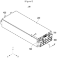
- FIG. 1 is a perspective view of a battery module according to an embodiment of the present invention.
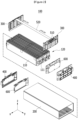
- FIG. 2 is an exploded perspective view of the battery module of FIG. 1 .
- a battery module 100 includes: a battery cell stack 120 where a plurality of battery cells 110 are stacked; a module frame 200 that accommodates the battery cell stack 120; and end plates 400 disposed at one end and the other end of the battery cell stack 120.
- the battery cell 110 may be a pouch-type battery cell.
- the battery cell 110 may be formed in a rectangular sheet-like structure.
- the battery cell 110 according to the present embodiment may have a structure in which two electrode leads 111 face each other and protrude to one side and the other side, respectively.
- the electrode lead 111 is connected to the electrode assembly (not shown), and protruded from the electrode assembly (not shown) to the outside of the battery cell 110.
- the battery cell 110 may be manufactured by heat-sealing the exterior circumference of the pouch-type cell case in a state where the electrode assembly (not shown) is accommodated in the pouch-type cell case.
- the pouch-type cell case may be formed of a laminate sheet including a resin layer and a metal layer.
- the battery cells 110 are configured in a plurality, and a plurality of battery cells 110 are stacked in one direction to be electrically connected to each other to form the battery cell stack 120.
- the plurality of battery cells 110 may be stacked in a direction that is parallel to the x-axis.
- the pouch-type cell case is generally formed of a laminate structure of a resin layer/metal thin film layer/resin layer.
- the surface of the pouch-type cell case is formed of an O (oriented)-nylon layer and when a plurality of battery cells 110 are stacked to form a medium or large battery module, it is not easily slid by external impact.
- an adhesive member such as a double-sided adhesive tape or a chemical adhesive bonded by a chemical reaction during adhesion is used on the surface of the pouch-type cell case may attached to form a battery cell stack 120.
- the battery cell stack 120 is accommodated in the module frame 200.
- the module frame 200 may be a metal frame with both sides open. More specifically, the module frame 200 may be opened in both directions in which the electrode lead 111 is protruded based on the battery cell stack 120.
- the module frame 200 shown in FIG. 2 is an example of the structure, and as long as it can accommodate the battery cell stack 120, there is no particular limitation in its form.
- the module frame 200 of FIG. 2 is shown as a mono frame in the form of a metal plate in which an upper side, a lower side, and lateral sides are integrated, but any form in which an upper cover is joined to an open U-shaped frame or a form in which a U-shaped frame and an inverted U-shaped frame are combined with each other is possible.
- the end plates 400 are positioned on one side and the other side of the battery cell stack 120. That is, the end plates 400 may be positioned on open lateral sides of the module frame 200.
- the module frame 200 and the end plate 400 may be joined by a welding method while the corresponding corners are in contact with each other. However, this is an example of the method, and bolt fastening, hook fastening, and the like may be applied as a mechanical coupling form. Since the battery cell stack 120 is accommodated in a space formed by the module frame 200 and the end plates 400, the battery cell stack 120 can be physically protected.
- the module frame 200 and the end plate 400 may include a metal material having predetermined strength such as aluminum or a plastic material.
- the battery module 100 includes a busbar frame 300 positioned between the battery cell stack 120 and the end plate 400.
- the battery module 100 may include an insulation cover 600 positioned between the busbar frame 300 and the end plate 400. That is, the busbar frame 300, the insulation cover 600, and the end plate 400 may be sequentially positioned from the battery cell stack 120 to the outside.
- the busbar frame 300 and the insulation cover 600 may each be configured in a plurality.
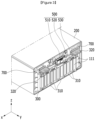
- FIG. 3 is a perspective view of a state in which the end plate and the insulation cover are removed from the battery module according to the embodiment of the present invention.
- (a) and (b) show a terminal busbar included in the battery module of FIG. 3 .
- FIG. 5 is a perspective view of the end plate and the insulation cover according to the embodiment of the present invention.
- the battery module 100 includes a busbar 320 mounted in the busbar frame 300.
- an opening 410H is formed in the end plate 400, and the terminal busbar 320 is exposed to the outside of the battery module 100 through the opening 410H.
- the battery module 100 may include a busbar 310 and a terminal busbar 320.
- the busbar 310 and the terminal busbar 320 may be mounted on the busbar frame 300.
- the busbar 310 and the terminal busbar 320 may be joined to the electrode lead 111 of the battery cell 110 to electrically connect a plurality of battery cells 110.
- the busbar frame 300 equipped with the busbar 310 and the terminal busbar 320 may be positioned on one side (y-axis direction) and the other side (-y-axis direction) of the battery cell stack 120, respectively.
- One side (y-axis direction) and the other side (-y-axis direction) of the battery cell stack 120 correspond to a direction in which the electrode lead 111 of the battery cell 110 is protruded. That is, as described above, any one busbar frame 300 may be positioned between any one of the end plates 400 and the battery cell stack 120.
- a lead slit is formed in the busbar frame 300, and the electrode lead 111 of the battery cell 110 passes through the lead slit and is bent to be bonded to the busbar 310 or the terminal busbar 320.
- a method of bonding there is no particular limitation on a method of bonding, and for example, welding bonding can be used. That is, the battery cells 110 may be electrically connected to each other via the busbar 310.
- the terminal busbar 310 may include a first portion 321 connected to the electrode lead 111 of the battery cell 110 and a second portion 322 exposed to the outside through an opening 410H.
- the second portion 322 exposed to the outside of the battery module 100 may be connected to another battery module or a battery disconnect unit (BDU) to form a high voltage (HV) connection.
- HV connection is a connection that serves as a power source for supplying power, and refers to a connection between battery cells or a connection between battery modules. That is, the battery module 100 may be electrically connected to another neighboring battery module via the terminal busbar 320.
- the battery module 100 may further include a sensing assembly 500.
- the sensing assembly 500 is provided for a low voltage (LV) connection, and the LV connection implies a sensing connection for sensing and controlling a voltage and a temperature of a battery cell.
- the voltage information and temperature information of the battery cell 110 may be measured through the sensing assembly 500 and transmitted to an external BMS (Battery Management System).
- the sensing assembly 500 according to the present embodiment may include a module connector 510, a connection cable 520, and a bonding member 530.
- the module connector 510 is a configuration for transmitting and receiving signals to and from an external control device.
- a connector opening 420H is formed on the end plate 400, the module connector 510 is exposed to the outside of the battery module 100 through the connector opening 420H, and the module connector 510 may be connected to an external BMS.
- connection cable 520 is a configuration for connecting the module connector 510 and the bonding member 530, and may be a flexible printed circuit board (FPCB) or a flexible flat cable (FFC).
- FPCB flexible printed circuit board
- FFC flexible flat cable
- the module connector 510 and connection cable 520 may be positioned on top of the busbar frame 300.
- the bonding member 530 may be connected to one end of the connection cable 520, and the bonding member 530 may be bonded to one side of the busbar 310 by a welding method.
- Voltage information for the plurality of battery cells 110 may be sequentially transmitted through the bonding member 530, the connection cable 520 and the module connector 510 to the external BMS.
- two busbar frames 300 may be disposed on one side and the other side of the battery cell stack 120, respectively.
- the module connector 510 may be positioned only in one busbar frame 300, and the module connector may not be positioned in the other busbar frame 300.
- the connection cable 520 may be extended from the module connector 510 to another busbar frame 300 such that the module connector 510 may be connected with the busbars 310 positioned on another busbar frame 300.
- An extended portion of the connection cable 520 may be positioned on the top of the battery cell stack 120.
- a temperature sensor may be provided on a part of the connection cable 520 positioned on an upper portion of the battery cell stack 120. Through the temperature sensor, the temperature information inside the battery module 100 may be sequentially transmitted through the connection cable 520 and the module connector 510 to the external BMS.
- the sensing assembly 500 may detect and control phenomena such as overvoltage, overcurrent, and overheating of each battery cell 110.
- the battery module 100 may include an insulation cover 600 positioned between the busbar frame 300 and the end plate 400.
- the insulation cover 600 is preferably provided in plural.
- the insulation cover 600 may contain a material that is electrically insulating and blocks contact of the busbar 310 or the terminal busbar 320 with the end plate 400.
- an opening hole 610H may be formed in a portion corresponding to the opening 410H of the end plate 400 among the insulation cover 600.
- the connector opening hole 610H may be formed in a portion corresponding to the connector opening 420H of the end plate 400 of the insulation cover 600.
- the terminal busbar 320 may be exposed to the outside of the battery module 100 through the opening hole 610H of the insulation cover 600 and the opening 410H of the end plate 400.
- the module connector 510 may be exposed to the outside of the battery module 100 through the connector opening hole 620H of the insulation cover 600 and the connector opening 410H of the end plate 400.
- the terminal busbar 320 is provided in plural, one of which may function as a positive terminal of the battery module 100, and the other may function as a negative terminal of the battery module 100. Accordingly, each of the opening 410H and the opening hole 610H may be provided in plural.
- FIG. 6 and FIG. 7 a blocking member according to an embodiment of the present invention will be described in detail.
- FIG. 6 and FIG. 7 are partial cross-sectional views of FIG. 1 , taken along the line A-A'.
- FIG. 6 is a cross-sectional view of the battery module in a normal condition
- FIG. 7 is a cross-sectional view of a case that a thermal runaway occurs in the battery module.
- the busbar frame 300 may include a blocking member 700 protruded toward the opening 410H.
- the blocking member 700 may be positioned inside the opening 410H.
- the blocking member 700 may be formed in a portion corresponding to the opening 410H of the end plate 400 of the busbar frame 300.
- the terminal busbar 320 is mounted on one side of the busbar frame 300, and the blocking member 700 may be positioned on the side of the busbar frame 300.
- the blocking member 700 may have a shape protruded toward the opening 410H on the one side of the busbar frame 300, and may be positioned between the terminal busbar 320 and an inner side of the opening 410H.
- a thermal runaway phenomenon may occur in the battery cells 110 inside the battery module 100.
- An example of a thermal runaway phenomenon is as follows. Physical, thermal, and electrical damage may occur to the battery cell 110 including overcharge, and the internal pressure of the battery cell 110 may increase. When the fusion strength limit of the pouch-type cell case of the battery cell 110 is exceeded, high temperature heat and venting gas generated in the battery cell 110 may be ejected to the outside of the battery cell 110.
- the thermal runaway phenomenon occurring in one battery cell may be extended to other battery cells due to the convection effect, and eventually high temperature gas and flame may be generated inside the battery module 100.
- the generated high-temperature gas and flame may be ejected to the outside through the opening 410H of the end plate 400, causing damage to an adjacent battery module or inducing another thermal runaway phenomenon in the adjacent battery module.
- a thermal runaway phenomenon propagates to a plurality of battery modules, which may cause explosion and ignition of the battery pack.
- the blocking member 700 capable of blocking the opening 410H of the end plate 400 according to the increase in the internal pressure of the module frame 200 is provided inside the opening 41 0H.
- An internal pressure of the module frame 200 means an air pressure of the inner space of the module frame 200 in which the battery cell stack 120 is accommodated.
- the increase in the internal pressure of the module frame 200 means that a large amount of gas is generated in the inner space of the module frame 200 due to the thermal runaway phenomenon.
- the blocking member 700 positioned inside the opening 410H approaches the opening 410H, and eventually the gap between the opening 410H and the terminal busbar 320 may be closed. Accordingly, it is possible to suppress the ejection of high temperature gas or flame to the outside of the battery module 100. That is, the gap where high temperature gas and flame may be ejected can be offset by increasing the internal pressure of the battery module 100. Accordingly, it is possible to prevent the thermal runaway phenomenon occurring in one battery module from propagating to other battery modules.
- the terminal busbar 320 may include a first portion 321 connected to the electrode lead 111 of the battery cell 110 and a second portion 322 exposed to the outside through the opening 410H.
- the terminal busbar 320 may further include a bending portion 323 formed between the first portion 321 and the second portion 322. Accordingly, one surface of the first portion 321 and one surface of the second portion 322 may be perpendicular to each other.
- the blocking member 700 may be positioned between the inner side of the opening 410H and the bending portion 323, or between the inner side of the opening 410H and the second portion 322.
- the terminal busbar 320 may be connected to another battery module or a battery disconnect unit (BDU) via a connection member (not shown).
- the terminal busbar 320 and the connecting member (not shown) may be bonded by a method such as welding.
- one side of the second part 322 is disposed side by side with the ground by forming the bent bending portion 323 on the terminal busbar 320, and thus bonding of the second part 322 and the connecting member (not shown) can be facilitated.
- a gap is naturally formed between the inner side of the opening 410H and the bending portion 323 or between the inner side of the opening 410H and the second portion 322, and high temperature gas and flame are intensively ejected through the gap.
- the blocking member 700 is positioned inside of opening 410H, particularly, between the inner side of opening 410H and the bending portion 323 or between the inner side of opening 410H and the second portion 322, and thus, when the internal pressure of module frame 200 is increased, the blocking member 700 can close the gap.
- the battery module 100 may further include the insulation cover 600 positioned between the busbar frame 300 and the end plate 400, and an opening hole 610H may be formed in the portion corresponding to the opening 410H of the insulation cover 600.
- the terminal busbar 320 may be exposed to the outside of the battery module 100 through the opening hole 610H of the insulation cover 600 and the opening 410H of the end plate 400.
- the opening hole 610H may be smaller than the opening 410H to ensure insulation, and an inner side of the opening hole 610H may be positioned closer to the terminal busbar 320 than the inner side of the opening 410H.
- the blocking member 700 according to the present embodiment may be positioned between the terminal busbar 320 and the inner side of the opening hole 610H. More specifically, the blocking member 700 may be positioned between the inner side of the opening hole 610H and the bending portion 323, or between the inner side of the opening hole 610H and the second portion 322.
- the blocking member 700 becomes close to the opening hole 610H, and the gap between the opening hole 610H and the terminal busbar 320 can be closed. Due to such an operation principle of the blocking member 700, high temperature gas or flame can be prevented from being ejected to the outside of the battery module 100.
- the shape of the blocking member 700 preferably corresponds to the opening area of the opening 410H or the opening hole 610H.
- the blocking member 700 may have a shape extending along the horizontal direction.
- the blocking member 700 may include a protruded portion 710 protruded from one side of the busbar frame 300 and a blocking portion 720 surrounding the protruded portion 710.
- the busbar frame 300 may be an insulating plastic member, and may be manufactured by injection molding as an example.
- the protruded portion 710 may be designed to be formed on one side of the busbar frame 300 during the injection molding process. That is, the protruded portion 710 may be integrated with the busbar frame 300.
- the blocking portion 720 may include at least one of a foam-type material and a resin material. It is possible to manufacture the blocking member 700 according to the present embodiment by covering the blocking portion 720 on the protruded portion 710. On the other hand, it is preferable that the foam material and the resin material are nonflammable.
- the blocking portion 720 may include at least one of an epoxy-based resin, a vinyl chloride-based resin, and a fluorine-based resin.
- the internal temperature of the battery module 100 may increase when a thermal runaway phenomenon occurs, and the blocking portion 720 may expand according to the temperature increase.
- the blocking portion 720 is expanded more than the blocking portion 720 shown in FIG. 6 .
- the expanded blocking portion 720 is more effective in closing the gap between the opening 410H and the terminal busbar 320 or between the opening hole 610Hand the terminal busbar 320.
- One or more battery modules according to the present embodiment described above may be mounted together with various control and protection systems such as a battery management system (BMS), a battery disconnect unit (BDU), and a cooling system to form a battery pack.
- BMS battery management system
- BDU battery disconnect unit
- the battery module or battery pack can be applied to various devices. Specifically, it can be applied to transportation means such as electric bicycles, electric vehicles, hybrids, or energy storage system (ESS), but is not limited thereto and can be applied to various devices that can use rechargeable batteries.
- transportation means such as electric bicycles, electric vehicles, hybrids, or energy storage system (ESS), but is not limited thereto and can be applied to various devices that can use rechargeable batteries.
- ESS energy storage system
Landscapes
- Chemical & Material Sciences (AREA)
- Chemical Kinetics & Catalysis (AREA)
- Electrochemistry (AREA)
- General Chemical & Material Sciences (AREA)
- Battery Mounting, Suspending (AREA)
- Connection Of Batteries Or Terminals (AREA)
Abstract
Description
- This application claims priority to and the benefit of
Korean Patent Application No. 10-2021-0069473 filed in the Korean Intellectual Property Office on May 28, 2021 - The present invention relates to a battery module and a battery pack including the same, and more particularly, it relates to a battery module that can suppress propagation of thermal runaway, and a battery pack including the same.
- In modern society, as portable devices such as mobile phones, laptops, camcorders, and digital cameras are used in daily life, the development of technologies related to mobile devices as described above is becoming active. In addition, since a rechargeable batterie that can be charged and discharged is being used as a power source of electric vehicles (EV), hybrid electric vehicles (HEV), and plug-in hybrid electric vehicles (P-HEV), the need for rechargeable battery development is increasing as a method for solving air pollution of conventional gasoline vehicles that use fossil fuels.
- Currently commercially available rechargeable batteries include a nickel cadmium battery, a nickel hydrogen battery, a nickel zinc battery, and a lithium rechargeable battery, and the lithium rechargeable battery is attracting attention for its merits of charging and discharging freely, its self-discharge rate is very low, and its energy density is high because it has almost no memory effect compared to the nickel-based rechargeable battery.
- The lithium rechargeable battery mainly uses a lithium-based oxide and a carbon material as positive and negative active materials, respectively. A lithium rechargeable battery includes an electrode assembly in which the positive and negative electrode plates are respectively coated with these positive and negative active materials with a separator interposed therebetween, and an exterior material that seals and houses the electrode assembly together with an electrolyte solution, that is, a battery case.
- In general, a lithium rechargeable battery can be classified into a can-type rechargeable battery in which the electrode assembly is built into a metal can and a pouch-type secondary battery in which the electrode assembly is built in a pouch of an aluminum laminate sheet according to the shape of the exterior material.
- In the case of a rechargeable battery used in small devices, two to three battery cells are disposed, but in the case of a rechargeable battery used in a medium or large device such as an automobile, a battery module in which a plurality of battery cells are electrically connected is used. In such a battery module, a plurality of battery cells are coupled serially or in parallel to form a battery cell stack, and thus capacity and output are improved. In addition, at least one battery module may be mounted together with various control and protection systems such as a battery management system (BMS) and a cooling system to form a battery pack.
- In a battery pack in which a plurality of battery modules are gathered, heat from a plurality of battery cells is added up in a narrow space, and the temperature may rise rapidly and severely. In other words, in the case of battery modules in which a plurality of battery cells are stacked and a battery pack in which the battery modules are mounted, high output may be obtained, but it is not easy to remove heat generated from the battery cells during charging and discharging. When the heat dissipation of the battery cell is not performed properly, the deterioration of the battery cell is accelerated, the cycle-life is shortened, and the possibility of explosion or ignition increases.
- Moreover, in the case of a battery module included in a vehicle battery pack, it is frequently exposed to direct sunlight and may be subjected to high temperature conditions such as summer or desert areas. In addition, since a plurality of battery modules are intensively disposed to increase the mileage of the vehicle, a thermal runaway phenomenon occurring in one battery module is easily propagated to a neighboring battery module, and ultimately the battery pack itself is damaged, thereby causing firing or explosion.
- Therefore, it is necessary to design a model that does not lead to fire or explosion of the battery pack itself, even though a thermal runaway phenomenon occurs in one battery module.
- The problem to be solved by the present invention is to provide a battery module that can suppress ejection of high temperature gas and flame even when a thermal runaway phenomenon occurs within the battery module and, a battery pack including the same.
- However, the problems to be solved by the embodiments of the present invention are not limited to the above-described problems and can be variously expanded in the range of technical ideas included in the present invention.
- A battery module according to an embodiment of the present invention includes: a battery cell stack where a plurality of battery cells are stacked; a module frame that accommodates the battery cell stack; end plates that are positioned at one side and the other side of the battery cell stack, and having openings; a busbar frame that is positioned between the battery cell stack and the end plate; and a terminal busbar that is mounted to the busbar frame, and exposed through the opening. The busbar frame includes a blocking member protruded toward the opening.
- The blocking member may be positioned between the terminal busbar and an inner side of the opening.
- The blocking member may be formed in a portion of the busbar frame, corresponding to the opening.
- The blocking member may include a protruded portion protruded from one side of the busbar frame and a blocking portion surrounding the protruded portion.
- The blocking portion may include at least one of a foam type of material and a resin material.
- The blocking portion may include at least one of an epoxy-based resin, a vinyl chloride-based resin, and a fluorine-based resin.
- The terminal busbar may be mounted on one side of the busbar frame in a direction where the end plate is positioned, and the blocking member may be positioned on the side of the busbar frame.
- The battery module may further include an insulation cover positioned between the busbar frame and the end plate. An opening hole may be formed in a portion of the insulation cover, corresponding to the opening.
- The blocking member may be positioned between the terminal busbar and an inner side of the opening hole.
- The terminal busbar may include a first portion connected with an electrode lead of the battery cell and a second portion exposed to the outside through the opening.
- The terminal busbar may further include a bending portion formed between the first portion and the second portion. The blocking member may be positioned between the inner side of the opening and the bending portion, or between the inner side of the opening and the second portion.
- According to the embodiment of the present invention, when a thermal runaway phenomenon occurs in the battery module, the pressure inside the battery module increases, and accordingly, the blocking member may block a gap formed in the battery module. That is, the gap where high temperature gas and flame may be ejected can be offset by using the increase in pressure inside the battery module.
- Effects of the present invention are not limited to the effects mentioned above, and other effects not mentioned will be clearly understood by a person of an ordinary skill in the art from the description of the claimed range.
-
-
FIG. 1 is a perspective view of a battery module according to an embodiment of the present invention. -
FIG. 2 is an exploded perspective view of the battery module ofFIG. 1 . -
FIG. 3 is a perspective view of a state in which an end plate and an insulation cover are removed from the battery module according to the embodiment of the present invention. - (a) and (b) of
FIG. 4 show a terminal busbar included in the battery module ofFIG. 3 . -
FIG. 5 is a perspective view of the end plate and the insulation cover according to the embodiment of the present invention. -
FIG. 6 andFIG. 7 are partial cross-sectional views ofFIG. 1 , taken along the line A-A'. - Hereinafter, with reference to the accompanying drawing, various embodiments of the present invention will be described in detail and thus a person of an ordinary skill can easily perform it in the technical field to which the present invention belongs. The present invention may be implemented in several different forms and is not limited to the embodiments described herein.
- In order to clearly explain the present invention, parts irrelevant to the description are omitted, and the same reference sign is attached to the same or similar constituent elements throughout the specification.
- In addition, since the size and thickness of each component shown in the drawing are arbitrarily indicated for convenience of explanation, the present invention is not necessarily limited to the illustrated contents. In the drawings, the thickness of layers, films, panels, regions, etc., are exaggerated for clarity. In addition, in the drawing, for convenience of explanation, the thickness of some layers and regions is exaggerated.
- It will be understood that when an element such as a layer, film, region, or substrate is referred to as being "on" another element, it can be directly on the other element or intervening elements may also be present. In contrast, when an element is referred to as being "directly on" another element, there are no intervening elements present. In addition, when a component is described as being positioned "above" or "on" a reference part, the component may be positioned "above" or "below" the reference part, and this configuration does not necessarily mean that the component is positioned "above" or "on" the reference part in a direction opposite to gravity.
- In addition, unless explicitly described to the contrary, the word "comprise", and variations such as "comprises" or "comprising", will be understood to imply the inclusion of stated elements but not the exclusion of any other elements.
- Throughout the specification, the word "in a plan view" means when an object is viewed from above, and the word "in a cross-sectional view" means when a cross section made by vertically cutting an object is viewed from a lateral side.
-
FIG. 1 is a perspective view of a battery module according to an embodiment of the present invention.FIG. 2 is an exploded perspective view of the battery module ofFIG. 1 . - Referring to
FIG. 1 andFIG. 2 , abattery module 100 according to an embodiment of the present invention includes: abattery cell stack 120 where a plurality ofbattery cells 110 are stacked; amodule frame 200 that accommodates thebattery cell stack 120; andend plates 400 disposed at one end and the other end of thebattery cell stack 120. - First, the
battery cell 110 may be a pouch-type battery cell. Thebattery cell 110 may be formed in a rectangular sheet-like structure. For example, thebattery cell 110 according to the present embodiment may have a structure in which two electrode leads 111 face each other and protrude to one side and the other side, respectively. In more detail, theelectrode lead 111 is connected to the electrode assembly (not shown), and protruded from the electrode assembly (not shown) to the outside of thebattery cell 110. - On the other hand, the
battery cell 110 may be manufactured by heat-sealing the exterior circumference of the pouch-type cell case in a state where the electrode assembly (not shown) is accommodated in the pouch-type cell case. The pouch-type cell case may be formed of a laminate sheet including a resin layer and a metal layer. - On the other hand, although only the
battery cell 110 having a structure in which theelectrode lead 111 is protruded in both directions of one side and the other side has been described, as another embodiment of the present invention, a single-direction pouch-type battery cell in which theelectrode lead 111 is protruded together in one direction is also possible. - The
battery cells 110 are configured in a plurality, and a plurality ofbattery cells 110 are stacked in one direction to be electrically connected to each other to form thebattery cell stack 120. For example, as shown inFIG. 2 , the plurality ofbattery cells 110 may be stacked in a direction that is parallel to the x-axis. The pouch-type cell case is generally formed of a laminate structure of a resin layer/metal thin film layer/resin layer. For example, when the surface of the pouch-type cell case is formed of an O (oriented)-nylon layer and when a plurality ofbattery cells 110 are stacked to form a medium or large battery module, it is not easily slid by external impact. Therefore, in order to prevent such a problem and maintain a stable stacking structure of battery cells, an adhesive member such as a double-sided adhesive tape or a chemical adhesive bonded by a chemical reaction during adhesion is used on the surface of the pouch-type cell case may attached to form abattery cell stack 120. - The
battery cell stack 120 is accommodated in themodule frame 200. Themodule frame 200 may be a metal frame with both sides open. More specifically, themodule frame 200 may be opened in both directions in which theelectrode lead 111 is protruded based on thebattery cell stack 120. However, themodule frame 200 shown inFIG. 2 is an example of the structure, and as long as it can accommodate thebattery cell stack 120, there is no particular limitation in its form. Themodule frame 200 ofFIG. 2 is shown as a mono frame in the form of a metal plate in which an upper side, a lower side, and lateral sides are integrated, but any form in which an upper cover is joined to an open U-shaped frame or a form in which a U-shaped frame and an inverted U-shaped frame are combined with each other is possible. - The
end plates 400 are positioned on one side and the other side of thebattery cell stack 120. That is, theend plates 400 may be positioned on open lateral sides of themodule frame 200. - The
module frame 200 and theend plate 400 may be joined by a welding method while the corresponding corners are in contact with each other. However, this is an example of the method, and bolt fastening, hook fastening, and the like may be applied as a mechanical coupling form. Since thebattery cell stack 120 is accommodated in a space formed by themodule frame 200 and theend plates 400, thebattery cell stack 120 can be physically protected. For this purpose, themodule frame 200 and theend plate 400 may include a metal material having predetermined strength such as aluminum or a plastic material. - Meanwhile, the
battery module 100 according to the present embodiment includes abusbar frame 300 positioned between thebattery cell stack 120 and theend plate 400. In addition, thebattery module 100 may include aninsulation cover 600 positioned between thebusbar frame 300 and theend plate 400. That is, thebusbar frame 300, theinsulation cover 600, and theend plate 400 may be sequentially positioned from thebattery cell stack 120 to the outside. Like theend plate 400, thebusbar frame 300 and theinsulation cover 600 may each be configured in a plurality. - Hereinafter, referring to
FIG. 3 to FIG. 5 , an opening formed in a terminal bus bar and the end plate according to the present embodiment will be described in detail. -
FIG. 3 is a perspective view of a state in which the end plate and the insulation cover are removed from the battery module according to the embodiment of the present invention. InFIG. 4, (a) and (b) show a terminal busbar included in the battery module ofFIG. 3 .FIG. 5 is a perspective view of the end plate and the insulation cover according to the embodiment of the present invention. - Referring to
FIG. 2 to FIG. 5 , thebattery module 100 according to the embodiment of the present invention includes abusbar 320 mounted in thebusbar frame 300. In particular, anopening 410H is formed in theend plate 400, and theterminal busbar 320 is exposed to the outside of thebattery module 100 through theopening 410H. - More specifically, the
battery module 100 according to the present embodiment may include abusbar 310 and aterminal busbar 320. Thebusbar 310 and theterminal busbar 320 may be mounted on thebusbar frame 300. - The
busbar 310 and theterminal busbar 320 may be joined to theelectrode lead 111 of thebattery cell 110 to electrically connect a plurality ofbattery cells 110. Specifically, thebusbar frame 300 equipped with thebusbar 310 and theterminal busbar 320 may be positioned on one side (y-axis direction) and the other side (-y-axis direction) of thebattery cell stack 120, respectively. One side (y-axis direction) and the other side (-y-axis direction) of thebattery cell stack 120 correspond to a direction in which theelectrode lead 111 of thebattery cell 110 is protruded. That is, as described above, any onebusbar frame 300 may be positioned between any one of theend plates 400 and thebattery cell stack 120. - A lead slit is formed in the
busbar frame 300, and theelectrode lead 111 of thebattery cell 110 passes through the lead slit and is bent to be bonded to thebusbar 310 or theterminal busbar 320. As long as physical and electrical connection is possible, there is no particular limitation on a method of bonding, and for example, welding bonding can be used. That is, thebattery cells 110 may be electrically connected to each other via thebusbar 310. - On the other hand, a part of the
terminal busbar 320 is exposed to the outside of thebattery module 100. Specifically, anopening 410H is formed on theend plate 400, and a portion of theterminal busbar 320 is exposed through theopening 410H. More specifically, theterminal busbar 310 may include afirst portion 321 connected to theelectrode lead 111 of thebattery cell 110 and asecond portion 322 exposed to the outside through anopening 410H. - The
second portion 322 exposed to the outside of thebattery module 100 may be connected to another battery module or a battery disconnect unit (BDU) to form a high voltage (HV) connection. Here, the HV connection is a connection that serves as a power source for supplying power, and refers to a connection between battery cells or a connection between battery modules. That is, thebattery module 100 may be electrically connected to another neighboring battery module via theterminal busbar 320. - Meanwhile, the
battery module 100 according to the present embodiment may further include asensing assembly 500. Here, thesensing assembly 500 is provided for a low voltage (LV) connection, and the LV connection implies a sensing connection for sensing and controlling a voltage and a temperature of a battery cell. The voltage information and temperature information of thebattery cell 110 may be measured through thesensing assembly 500 and transmitted to an external BMS (Battery Management System). Thesensing assembly 500 according to the present embodiment may include amodule connector 510, aconnection cable 520, and abonding member 530. - The
module connector 510 is a configuration for transmitting and receiving signals to and from an external control device. Aconnector opening 420H is formed on theend plate 400, themodule connector 510 is exposed to the outside of thebattery module 100 through theconnector opening 420H, and themodule connector 510 may be connected to an external BMS. - The
connection cable 520 is a configuration for connecting themodule connector 510 and thebonding member 530, and may be a flexible printed circuit board (FPCB) or a flexible flat cable (FFC). Themodule connector 510 andconnection cable 520 may be positioned on top of thebusbar frame 300. - The
bonding member 530 may be connected to one end of theconnection cable 520, and thebonding member 530 may be bonded to one side of thebusbar 310 by a welding method. - Voltage information for the plurality of
battery cells 110 may be sequentially transmitted through thebonding member 530, theconnection cable 520 and themodule connector 510 to the external BMS. - Meanwhile, as shown in
FIG. 2 , twobusbar frames 300 may be disposed on one side and the other side of thebattery cell stack 120, respectively. In this case, themodule connector 510 may be positioned only in onebusbar frame 300, and the module connector may not be positioned in theother busbar frame 300. Theconnection cable 520 may be extended from themodule connector 510 to anotherbusbar frame 300 such that themodule connector 510 may be connected with thebusbars 310 positioned on anotherbusbar frame 300. An extended portion of theconnection cable 520 may be positioned on the top of thebattery cell stack 120. A temperature sensor may be provided on a part of theconnection cable 520 positioned on an upper portion of thebattery cell stack 120. Through the temperature sensor, the temperature information inside thebattery module 100 may be sequentially transmitted through theconnection cable 520 and themodule connector 510 to the external BMS. - In the above manner, the
sensing assembly 500 may detect and control phenomena such as overvoltage, overcurrent, and overheating of eachbattery cell 110. - Meanwhile, as described above, the
battery module 100 according to the present embodiment may include aninsulation cover 600 positioned between thebusbar frame 300 and theend plate 400. Theinsulation cover 600 is preferably provided in plural. Theinsulation cover 600 may contain a material that is electrically insulating and blocks contact of thebusbar 310 or theterminal busbar 320 with theend plate 400. - Referring to
FIG. 3 to FIG. 5 , anopening hole 610H may be formed in a portion corresponding to theopening 410H of theend plate 400 among theinsulation cover 600. In addition, theconnector opening hole 610H may be formed in a portion corresponding to theconnector opening 420H of theend plate 400 of theinsulation cover 600. - The
terminal busbar 320 according to the present embodiment may be exposed to the outside of thebattery module 100 through theopening hole 610H of theinsulation cover 600 and theopening 410H of theend plate 400. In addition, themodule connector 510 may be exposed to the outside of thebattery module 100 through theconnector opening hole 620H of theinsulation cover 600 and theconnector opening 410H of theend plate 400. - On the other hand, the
terminal busbar 320 is provided in plural, one of which may function as a positive terminal of thebattery module 100, and the other may function as a negative terminal of thebattery module 100. Accordingly, each of theopening 410H and theopening hole 610H may be provided in plural. - Hereinafter, referring to
FIG. 6 andFIG. 7 , a blocking member according to an embodiment of the present invention will be described in detail. -
FIG. 6 andFIG. 7 are partial cross-sectional views ofFIG. 1 , taken along the line A-A'. In this case,FIG. 6 is a cross-sectional view of the battery module in a normal condition, andFIG. 7 is a cross-sectional view of a case that a thermal runaway occurs in the battery module. - Referring to
FIG. 3 ,FIG. 4 ,FIG. 6 , andFIG. 7 , thebusbar frame 300 according to the embodiment of the present invention may include a blockingmember 700 protruded toward theopening 410H. The blockingmember 700 may be positioned inside theopening 410H. - Specifically, the blocking
member 700 may be formed in a portion corresponding to theopening 410H of theend plate 400 of thebusbar frame 300. Theterminal busbar 320 is mounted on one side of thebusbar frame 300, and the blockingmember 700 may be positioned on the side of thebusbar frame 300. Particularly, the blockingmember 700 may have a shape protruded toward theopening 410H on the one side of thebusbar frame 300, and may be positioned between theterminal busbar 320 and an inner side of theopening 410H. - A thermal runaway phenomenon may occur in the
battery cells 110 inside thebattery module 100. An example of a thermal runaway phenomenon is as follows. Physical, thermal, and electrical damage may occur to thebattery cell 110 including overcharge, and the internal pressure of thebattery cell 110 may increase. When the fusion strength limit of the pouch-type cell case of thebattery cell 110 is exceeded, high temperature heat and venting gas generated in thebattery cell 110 may be ejected to the outside of thebattery cell 110. - The thermal runaway phenomenon occurring in one battery cell may be extended to other battery cells due to the convection effect, and eventually high temperature gas and flame may be generated inside the
battery module 100. The generated high-temperature gas and flame may be ejected to the outside through theopening 410H of theend plate 400, causing damage to an adjacent battery module or inducing another thermal runaway phenomenon in the adjacent battery module. Ultimately, a thermal runaway phenomenon propagates to a plurality of battery modules, which may cause explosion and ignition of the battery pack. - Accordingly, in the
battery module 100 according to the present embodiment, the blockingmember 700 capable of blocking theopening 410H of theend plate 400 according to the increase in the internal pressure of themodule frame 200 is provided inside the opening 41 0H. An internal pressure of themodule frame 200 means an air pressure of the inner space of themodule frame 200 in which thebattery cell stack 120 is accommodated. The increase in the internal pressure of themodule frame 200 means that a large amount of gas is generated in the inner space of themodule frame 200 due to the thermal runaway phenomenon. - During thermal runaway, gas is ejected from the battery cells, and the internal pressure of the
module frame 200 is increased. As the internal pressure is increased, thebusbar frame 300 may be closely adhered to theend plate 400 side. In addition, a portion of thebusbar frame 300 may be bent toward theend plate 400 by an internal pressure P of themodule frame 200. InFIG. 7 , for the convenience of explanation, such a figure is expressed exaggeratedly. - Due to the increase of the internal pressure of the
module frame 200, the blockingmember 700 positioned inside theopening 410H approaches theopening 410H, and eventually the gap between theopening 410H and theterminal busbar 320 may be closed. Accordingly, it is possible to suppress the ejection of high temperature gas or flame to the outside of thebattery module 100. That is, the gap where high temperature gas and flame may be ejected can be offset by increasing the internal pressure of thebattery module 100. Accordingly, it is possible to prevent the thermal runaway phenomenon occurring in one battery module from propagating to other battery modules. - As described above, the
terminal busbar 320 may include afirst portion 321 connected to theelectrode lead 111 of thebattery cell 110 and asecond portion 322 exposed to the outside through theopening 410H. In addition, theterminal busbar 320 may further include a bendingportion 323 formed between thefirst portion 321 and thesecond portion 322. Accordingly, one surface of thefirst portion 321 and one surface of thesecond portion 322 may be perpendicular to each other. - The blocking
member 700 according to the present embodiment may be positioned between the inner side of theopening 410H and the bendingportion 323, or between the inner side of theopening 410H and thesecond portion 322. Although not specifically illustrated, theterminal busbar 320 may be connected to another battery module or a battery disconnect unit (BDU) via a connection member (not shown). Theterminal busbar 320 and the connecting member (not shown) may be bonded by a method such as welding. In this case, one side of thesecond part 322 is disposed side by side with the ground by forming thebent bending portion 323 on theterminal busbar 320, and thus bonding of thesecond part 322 and the connecting member (not shown) can be facilitated. - According to the above structure, a gap is naturally formed between the inner side of the
opening 410H and the bendingportion 323 or between the inner side of theopening 410H and thesecond portion 322, and high temperature gas and flame are intensively ejected through the gap. - The blocking
member 700 is positioned inside of opening 410H, particularly, between the inner side ofopening 410H and the bendingportion 323 or between the inner side ofopening 410H and thesecond portion 322, and thus, when the internal pressure ofmodule frame 200 is increased, the blockingmember 700 can close the gap. - On the other hand, as described above, the
battery module 100 according to the present embodiment may further include theinsulation cover 600 positioned between thebusbar frame 300 and theend plate 400, and anopening hole 610H may be formed in the portion corresponding to theopening 410H of theinsulation cover 600. In addition, theterminal busbar 320 may be exposed to the outside of thebattery module 100 through theopening hole 610H of theinsulation cover 600 and theopening 410H of theend plate 400. - In this case, the
opening hole 610H may be smaller than theopening 410H to ensure insulation, and an inner side of theopening hole 610H may be positioned closer to theterminal busbar 320 than the inner side of theopening 410H. The blockingmember 700 according to the present embodiment may be positioned between theterminal busbar 320 and the inner side of theopening hole 610H. More specifically, the blockingmember 700 may be positioned between the inner side of theopening hole 610H and the bendingportion 323, or between the inner side of theopening hole 610H and thesecond portion 322. Therefore, when the thermal runaway phenomenon occurs, as the internal pressure of themodule frame 200 is increased, the blockingmember 700 becomes close to theopening hole 610H, and the gap between theopening hole 610H and theterminal busbar 320 can be closed. Due to such an operation principle of the blockingmember 700, high temperature gas or flame can be prevented from being ejected to the outside of thebattery module 100. - The shape of the blocking
member 700 preferably corresponds to the opening area of theopening 410H or theopening hole 610H. For example, referring toFIG. 3 andFIG. 5 , according to the shape of the opening of theopening hole 610H having a wider width in the horizontal direction than a width in the vertical direction, the blockingmember 700 may have a shape extending along the horizontal direction. - The blocking
member 700 according to the present embodiment may include a protrudedportion 710 protruded from one side of thebusbar frame 300 and a blockingportion 720 surrounding the protrudedportion 710. Specifically, thebusbar frame 300 may be an insulating plastic member, and may be manufactured by injection molding as an example. In this case, the protrudedportion 710 may be designed to be formed on one side of thebusbar frame 300 during the injection molding process. That is, the protrudedportion 710 may be integrated with thebusbar frame 300. - The blocking
portion 720 may include at least one of a foam-type material and a resin material. It is possible to manufacture the blockingmember 700 according to the present embodiment by covering the blockingportion 720 on the protrudedportion 710. On the other hand, it is preferable that the foam material and the resin material are nonflammable. - In addition, the blocking
portion 720 may include at least one of an epoxy-based resin, a vinyl chloride-based resin, and a fluorine-based resin. Referring toFIG. 6 andFIG. 7 , the internal temperature of thebattery module 100 may increase when a thermal runaway phenomenon occurs, and the blockingportion 720 may expand according to the temperature increase. Although it is exaggerated for convenience of explanation, but inFIG. 7 , the blockingportion 720 is expanded more than the blockingportion 720 shown inFIG. 6 . The expandedblocking portion 720 is more effective in closing the gap between theopening 410H and theterminal busbar 320 or between the opening hole 610Hand theterminal busbar 320. - In the present embodiment, terms indicating direction such as before, after, left, right, up, and down were used, but these terms are for convenience of explanation only, and may vary depending on the position of the object or the position of the observer.
- One or more battery modules according to the present embodiment described above may be mounted together with various control and protection systems such as a battery management system (BMS), a battery disconnect unit (BDU), and a cooling system to form a battery pack.
- The battery module or battery pack can be applied to various devices. Specifically, it can be applied to transportation means such as electric bicycles, electric vehicles, hybrids, or energy storage system (ESS), but is not limited thereto and can be applied to various devices that can use rechargeable batteries.
- While this invention has been described in connection with what is presently considered to be practical embodiments, it is to be understood that the invention is not limited to the disclosed embodiments. On the contrary, it is intended to cover various modifications and equivalent arrangements included within the spirit and scope of the appended claims.
-
- 100: battery module
- 120: battery cell stack
- 200: module frame
- 300: busbar frame
- 320: terminal busbar
- 400: end plate
- 410H: opening
- 700: blocking member
Claims (12)
- A battery module comprising:a battery cell stack where a plurality of battery cells are stacked;a module frame that accommodates the battery cell stack;end plates that are positioned at one side and the other side of the battery cell stack, and having openings;a busbar frame that is positioned between the battery cell stack and the end plate; anda terminal busbar that is mounted to the busbar frame, and exposed through the opening,wherein the busbar frame comprises a blocking member protruded toward the opening.
- The battery module of claim 1, wherein
the blocking member is positioned between the terminal busbar and an inner side of the opening. - The battery module of claim 1, wherein
the blocking member is formed in a portion of the busbar frame, corresponding to the opening. - The battery module of claim 1, wherein
the blocking member comprises a protruded portion protruded from one side of the busbar frame and a blocking portion surrounding the protruded portion. - The battery module of claim 4, wherein
the blocking portion comprises at least one of a foam type of material and a resin material. - The battery module of claim 4, wherein
the blocking portion comprises at least one of an epoxy-based resin, a vinyl chloride-based resin, and a fluorine-based resin. - The battery module of claim 1, whereinthe terminal busbar is mounted on one side of the busbar frame in a direction where the end plate is positioned, andthe blocking member is positioned on the side of the busbar frame.
- The battery module of claim 1, further comprising an insulation cover positioned between the busbar frame and the end plate,
wherein an opening hole is formed in a portion of the insulation cover, corresponding to the opening. - The battery module of claim 8, wherein
the blocking member is positioned between the terminal busbar and an inner side of the opening hole. - The battery module of claim 1, wherein
the terminal busbar comprises a first portion connected with an electrode lead of the battery cell and a second portion exposed to the outside through the opening. - The battery module of claim 10, whereinthe terminal busbar further comprises a bending portion formed between the first portion and the second portion, andthe blocking member is positioned between the inner side of the opening and the bending portion, or between the inner side of the opening and the second portion.
- A battery pack comprising the battery module of claim 1.
Applications Claiming Priority (2)
| Application Number | Priority Date | Filing Date | Title |
|---|---|---|---|
| KR1020210069473A KR102945055B1 (en) | 2021-05-28 | 2021-05-28 | Battery module and battery pack including the same |
| PCT/KR2022/005217 WO2022250287A1 (en) | 2021-05-28 | 2022-04-11 | Battery module and battery pack including same |
Publications (2)
| Publication Number | Publication Date |
|---|---|
| EP4250457A1 true EP4250457A1 (en) | 2023-09-27 |
| EP4250457A4 EP4250457A4 (en) | 2025-03-19 |
Family
ID=84230064
Family Applications (1)
| Application Number | Title | Priority Date | Filing Date |
|---|---|---|---|
| EP22811480.7A Pending EP4250457A4 (en) | 2021-05-28 | 2022-04-11 | BATTERY MODULE AND BATTERY PACK |
Country Status (6)
| Country | Link |
|---|---|
| US (1) | US20240072375A1 (en) |
| EP (1) | EP4250457A4 (en) |
| JP (1) | JP7652510B2 (en) |
| KR (1) | KR102945055B1 (en) |
| CN (1) | CN116711140A (en) |
| WO (1) | WO2022250287A1 (en) |
Cited By (1)
| Publication number | Priority date | Publication date | Assignee | Title |
|---|---|---|---|---|
| CN117154177A (en) * | 2023-10-23 | 2023-12-01 | 苏州德星云智能装备有限公司 | Cold pressing stacking device of clearance module |
Families Citing this family (7)
| Publication number | Priority date | Publication date | Assignee | Title |
|---|---|---|---|---|
| KR20240082759A (en) * | 2022-12-02 | 2024-06-11 | 주식회사 엘지에너지솔루션 | CTP type high energy density battery pack |
| SE2251559A1 (en) * | 2022-12-22 | 2024-06-23 | Northvolt Systems Ab | An enclosure |
| CN219643022U (en) * | 2023-01-28 | 2023-09-05 | 浙江极氪智能科技有限公司 | Battery module, battery pack and vehicle |
| KR20250052867A (en) * | 2023-10-12 | 2025-04-21 | 주식회사 엘지에너지솔루션 | Secondary battery module |
| KR20250057291A (en) * | 2023-10-20 | 2025-04-29 | 주식회사 엘지에너지솔루션 | Battery module and battery pack including the same |
| KR20250066041A (en) * | 2023-11-06 | 2025-05-13 | 주식회사 엘지에너지솔루션 | Battery module and battery pack including the same |
| KR20260030517A (en) * | 2024-08-27 | 2026-03-06 | 주식회사 엘지에너지솔루션 | Battery pack, and vehicle including the same |
Family Cites Families (13)
| Publication number | Priority date | Publication date | Assignee | Title |
|---|---|---|---|---|
| JP6365884B2 (en) * | 2015-04-14 | 2018-08-01 | 豊田合成株式会社 | Assembled battery |
| DE102016103836A1 (en) * | 2016-03-03 | 2017-09-07 | Johnson Controls Advanced Power Solutions Gmbh | Battery connections for a lithium-ion battery module |
| JP7105081B2 (en) * | 2018-03-29 | 2022-07-22 | 三洋電機株式会社 | Assembled battery and secondary battery used therein |
| CN112335114B (en) * | 2018-06-26 | 2023-12-22 | 三洋电机株式会社 | Battery system, electric vehicle having battery system, and power storage device |
| KR102698844B1 (en) * | 2018-12-04 | 2024-08-23 | 주식회사 엘지에너지솔루션 | Battery pack |
| KR102367381B1 (en) * | 2018-12-26 | 2022-02-23 | 주식회사 엘지에너지솔루션 | A battery module having a structure capable of preventing foreign matter from entering, a battery pack and a vehicle comprising the same |
| KR102416919B1 (en) * | 2019-02-26 | 2022-07-04 | 주식회사 엘지에너지솔루션 | Battery module |
| KR102583650B1 (en) * | 2019-07-01 | 2023-09-26 | 주식회사 엘지에너지솔루션 | Battery module and battery pack including the same |
| CN209896150U (en) * | 2019-07-25 | 2020-01-03 | 中车时代电动汽车股份有限公司 | A high-voltage protection structure for a combined battery pack |
| CN111668419B (en) * | 2020-05-21 | 2022-04-12 | 合肥国轩高科动力能源有限公司 | A soft pack battery module and its assembly method |
| CN212033104U (en) * | 2020-06-02 | 2020-11-27 | 合肥国轩高科动力能源有限公司 | Soft pack battery module and its end cap |
| CN111554837B (en) * | 2020-06-02 | 2022-06-07 | 合肥国轩高科动力能源有限公司 | Laminate polymer battery module |
| KR102842469B1 (en) * | 2021-05-11 | 2025-08-04 | 주식회사 엘지에너지솔루션 | Battery module and battery pack including the same |
-
2021
- 2021-05-28 KR KR1020210069473A patent/KR102945055B1/en active Active
-
2022
- 2022-04-11 WO PCT/KR2022/005217 patent/WO2022250287A1/en not_active Ceased
- 2022-04-11 EP EP22811480.7A patent/EP4250457A4/en active Pending
- 2022-04-11 CN CN202280009835.6A patent/CN116711140A/en active Pending
- 2022-04-11 US US18/270,696 patent/US20240072375A1/en active Pending
- 2022-04-11 JP JP2023539908A patent/JP7652510B2/en active Active
Cited By (2)
| Publication number | Priority date | Publication date | Assignee | Title |
|---|---|---|---|---|
| CN117154177A (en) * | 2023-10-23 | 2023-12-01 | 苏州德星云智能装备有限公司 | Cold pressing stacking device of clearance module |
| CN117154177B (en) * | 2023-10-23 | 2024-04-05 | 苏州德星云智能装备有限公司 | Cold pressing stacking device of clearance module |
Also Published As
| Publication number | Publication date |
|---|---|
| WO2022250287A1 (en) | 2022-12-01 |
| JP2024501535A (en) | 2024-01-12 |
| KR20220161056A (en) | 2022-12-06 |
| CN116711140A (en) | 2023-09-05 |
| JP7652510B2 (en) | 2025-03-27 |
| EP4250457A4 (en) | 2025-03-19 |
| US20240072375A1 (en) | 2024-02-29 |
| KR102945055B1 (en) | 2026-03-26 |
Similar Documents
| Publication | Publication Date | Title |
|---|---|---|
| US20240072375A1 (en) | Battery module and battery pack including the same | |
| KR102611921B1 (en) | Battery module and battery pack including the same | |
| US20240030531A1 (en) | Battery module and battery pack including the same | |
| EP4087018A1 (en) | Battery pack and device including same | |
| US12626982B2 (en) | Battery module, battery pack including the same and manufacturing method of the same | |
| EP4184697A1 (en) | Battery module and battery pack including same | |
| US20230318078A1 (en) | Battery module and battery pack including the same | |
| EP4089792A1 (en) | Battery module, battery pack including same, and manufacturing method thereof | |
| US20240234920A9 (en) | Battery pack and device including the same | |
| EP4181292B1 (en) | Battery pack including battery modules | |
| EP4089813B1 (en) | Battery pack and device including the same | |
| KR102954856B1 (en) | Battery module and battery pack including the same | |
| US20260100463A1 (en) | Battery pack and device including the same | |
| EP4181286B1 (en) | BATTERY MODULE AND BATTERY BLOCK INCLUDING IT | |
| CN220121952U (en) | Battery module and battery pack including the battery module | |
| US12394872B2 (en) | Battery module and battery pack including the same | |
| US20230261307A1 (en) | Battery pack and device including the same | |
| KR20240101187A (en) | Battery cell and battery module including the same |
Legal Events
| Date | Code | Title | Description |
|---|---|---|---|
| STAA | Information on the status of an ep patent application or granted ep patent |
Free format text: STATUS: THE INTERNATIONAL PUBLICATION HAS BEEN MADE |
|
| PUAI | Public reference made under article 153(3) epc to a published international application that has entered the european phase |
Free format text: ORIGINAL CODE: 0009012 |
|
| STAA | Information on the status of an ep patent application or granted ep patent |
Free format text: STATUS: REQUEST FOR EXAMINATION WAS MADE |
|
| 17P | Request for examination filed |
Effective date: 20230619 |
|
| AK | Designated contracting states |
Kind code of ref document: A1 Designated state(s): AL AT BE BG CH CY CZ DE DK EE ES FI FR GB GR HR HU IE IS IT LI LT LU LV MC MK MT NL NO PL PT RO RS SE SI SK SM TR |
|
| DAV | Request for validation of the european patent (deleted) | ||
| DAX | Request for extension of the european patent (deleted) | ||
| REG | Reference to a national code |
Ref country code: DE Ref legal event code: R079 Free format text: PREVIOUS MAIN CLASS: H01M0050383000 Ipc: H01M0050211000 |
|
| A4 | Supplementary search report drawn up and despatched |
Effective date: 20250213 |
|
| RIC1 | Information provided on ipc code assigned before grant |
Ipc: H01M 50/383 20210101ALI20250207BHEP Ipc: H01M 50/557 20210101ALI20250207BHEP Ipc: H01M 50/507 20210101ALI20250207BHEP Ipc: H01M 50/503 20210101ALI20250207BHEP Ipc: H01M 50/296 20210101ALI20250207BHEP Ipc: H01M 50/211 20210101AFI20250207BHEP |
|
| STAA | Information on the status of an ep patent application or granted ep patent |
Free format text: STATUS: EXAMINATION IS IN PROGRESS |
|
| 17Q | First examination report despatched |
Effective date: 20250929 |