EP4250446A2 - Energy storage frame and energy storage battery cluster - Google Patents
Energy storage frame and energy storage battery cluster Download PDFInfo
- Publication number
- EP4250446A2 EP4250446A2 EP22174979.9A EP22174979A EP4250446A2 EP 4250446 A2 EP4250446 A2 EP 4250446A2 EP 22174979 A EP22174979 A EP 22174979A EP 4250446 A2 EP4250446 A2 EP 4250446A2
- Authority
- EP
- European Patent Office
- Prior art keywords
- insert box
- column
- energy storage
- plate
- battery
- Prior art date
- Legal status (The legal status is an assumption and is not a legal conclusion. Google has not performed a legal analysis and makes no representation as to the accuracy of the status listed.)
- Withdrawn
Links
- 238000004146 energy storage Methods 0.000 title claims abstract description 59
- 238000003780 insertion Methods 0.000 claims abstract description 29
- 230000037431 insertion Effects 0.000 claims abstract description 29
- 230000002787 reinforcement Effects 0.000 description 7
- 229920000515 polycarbonate Polymers 0.000 description 4
- 239000004417 polycarbonate Substances 0.000 description 4
- 238000005452 bending Methods 0.000 description 3
- 239000002184 metal Substances 0.000 description 3
- 239000007769 metal material Substances 0.000 description 3
- 238000003466 welding Methods 0.000 description 3
- 230000006978 adaptation Effects 0.000 description 2
- 238000005516 engineering process Methods 0.000 description 1
- 238000000034 method Methods 0.000 description 1
- 238000012986 modification Methods 0.000 description 1
- 230000004048 modification Effects 0.000 description 1
Images


Classifications
-
- H—ELECTRICITY
- H01—ELECTRIC ELEMENTS
- H01M—PROCESSES OR MEANS, e.g. BATTERIES, FOR THE DIRECT CONVERSION OF CHEMICAL ENERGY INTO ELECTRICAL ENERGY
- H01M50/00—Constructional details or processes of manufacture of the non-active parts of electrochemical cells other than fuel cells, e.g. hybrid cells
- H01M50/20—Mountings; Secondary casings or frames; Racks, modules or packs; Suspension devices; Shock absorbers; Transport or carrying devices; Holders
- H01M50/204—Racks, modules or packs for multiple batteries or multiple cells
-
- H—ELECTRICITY
- H01—ELECTRIC ELEMENTS
- H01M—PROCESSES OR MEANS, e.g. BATTERIES, FOR THE DIRECT CONVERSION OF CHEMICAL ENERGY INTO ELECTRICAL ENERGY
- H01M50/00—Constructional details or processes of manufacture of the non-active parts of electrochemical cells other than fuel cells, e.g. hybrid cells
- H01M50/20—Mountings; Secondary casings or frames; Racks, modules or packs; Suspension devices; Shock absorbers; Transport or carrying devices; Holders
- H01M50/244—Secondary casings; Racks; Suspension devices; Carrying devices; Holders characterised by their mounting method
-
- H—ELECTRICITY
- H01—ELECTRIC ELEMENTS
- H01M—PROCESSES OR MEANS, e.g. BATTERIES, FOR THE DIRECT CONVERSION OF CHEMICAL ENERGY INTO ELECTRICAL ENERGY
- H01M50/00—Constructional details or processes of manufacture of the non-active parts of electrochemical cells other than fuel cells, e.g. hybrid cells
- H01M50/20—Mountings; Secondary casings or frames; Racks, modules or packs; Suspension devices; Shock absorbers; Transport or carrying devices; Holders
- H01M50/233—Mountings; Secondary casings or frames; Racks, modules or packs; Suspension devices; Shock absorbers; Transport or carrying devices; Holders characterised by physical properties of casings or racks, e.g. dimensions
-
- H—ELECTRICITY
- H01—ELECTRIC ELEMENTS
- H01M—PROCESSES OR MEANS, e.g. BATTERIES, FOR THE DIRECT CONVERSION OF CHEMICAL ENERGY INTO ELECTRICAL ENERGY
- H01M50/00—Constructional details or processes of manufacture of the non-active parts of electrochemical cells other than fuel cells, e.g. hybrid cells
- H01M50/20—Mountings; Secondary casings or frames; Racks, modules or packs; Suspension devices; Shock absorbers; Transport or carrying devices; Holders
- H01M50/251—Mountings; Secondary casings or frames; Racks, modules or packs; Suspension devices; Shock absorbers; Transport or carrying devices; Holders specially adapted for stationary devices, e.g. power plant buffering or backup power supplies
-
- H—ELECTRICITY
- H01—ELECTRIC ELEMENTS
- H01M—PROCESSES OR MEANS, e.g. BATTERIES, FOR THE DIRECT CONVERSION OF CHEMICAL ENERGY INTO ELECTRICAL ENERGY
- H01M50/00—Constructional details or processes of manufacture of the non-active parts of electrochemical cells other than fuel cells, e.g. hybrid cells
- H01M50/20—Mountings; Secondary casings or frames; Racks, modules or packs; Suspension devices; Shock absorbers; Transport or carrying devices; Holders
- H01M50/289—Mountings; Secondary casings or frames; Racks, modules or packs; Suspension devices; Shock absorbers; Transport or carrying devices; Holders characterised by spacing elements or positioning means within frames, racks or packs
-
- Y—GENERAL TAGGING OF NEW TECHNOLOGICAL DEVELOPMENTS; GENERAL TAGGING OF CROSS-SECTIONAL TECHNOLOGIES SPANNING OVER SEVERAL SECTIONS OF THE IPC; TECHNICAL SUBJECTS COVERED BY FORMER USPC CROSS-REFERENCE ART COLLECTIONS [XRACs] AND DIGESTS
- Y02—TECHNOLOGIES OR APPLICATIONS FOR MITIGATION OR ADAPTATION AGAINST CLIMATE CHANGE
- Y02E—REDUCTION OF GREENHOUSE GAS [GHG] EMISSIONS, RELATED TO ENERGY GENERATION, TRANSMISSION OR DISTRIBUTION
- Y02E60/00—Enabling technologies; Technologies with a potential or indirect contribution to GHG emissions mitigation
- Y02E60/10—Energy storage using batteries
Definitions
- the invention provides an energy storage battery cluster, which includes the energy storage frame and at least one battery insert box, and the battery insert box is inserted into the energy storage frame.
- the energy storage frame of the invention by fixing the connection between the insert box storage rack 20 and the stand 10 in two directions, not only improves the connection strength between the stand 10 and the insert box storage rack 20 but also reduces the risk of the connection position failure resulting from the influence of the insertion force of the battery insert box between the stand 10 and the insert box storage rack 20, and thus the configuration stability of the battery insert box is secured.
Landscapes
- Chemical & Material Sciences (AREA)
- Chemical Kinetics & Catalysis (AREA)
- Electrochemistry (AREA)
- General Chemical & Material Sciences (AREA)
- Battery Mounting, Suspending (AREA)
Abstract
Description
- The invention relates to the technical field of batteries, and particularly, to an energy storage frame and an energy storage battery cluster.
- Energy storage devices are new energy devices that store a battery insert box in an energy storage frame. The connection stability between the storage rack and the column for the battery insert box of the current energy storage frame is poor. In the insertion process, the slot is subjected to the connection failure due to the force of the battery insert box.
- The invention provides an energy storage frame, which includes:
- a stand including a first column and a second column disposed side by side and at intervals;
- an insert box storage rack configured to support a battery insert box, in which the insert box storage rack is disposed on one side of the stand, the insert box storage rack includes a first connecting beam and a second connecting beam, the first connecting beam is connected to the first column along a first direction, the second connecting beam is connected to the second column along a second direction, the first direction is parallel to an insertion direction of the battery insert box, and the second direction is perpendicular to the insertion direction of the battery insert box.
- The invention provides an energy storage battery cluster, which includes the energy storage frame and at least one battery insert box, and the battery insert box is inserted into the energy storage frame.
- For a better understanding of the disclosure, reference may be made to exemplary embodiments shown in the following drawings. The components in the drawings are not necessarily to scale and related elements may be omitted, or in some instances proportions may have been exaggerated, so as to emphasize and clearly illustrate the features described herein. In addition, related elements or components can be variously arranged, as known in the art. Further, in the drawings, like reference numerals designate same or like parts throughout the several views.
-
FIG. 1 is a three-dimensional schematic view illustrating the structure of an energy storage frame of the invention. -
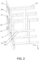
FIG. 2 is a schematic view illustrating part of the structure of the energy storage frame shown inFIG. 1 . -
FIG. 3 is a schematic view illustrating an enlarged structure of part A inFIG. 2 . -
FIG. 4 is a schematic view illustrating part of the structure of the energy storage frame shown inFIG. 2 from another perspective. -
FIG. 5 is a schematic view illustrating an enlarged structure of part B inFIG. 4 . -
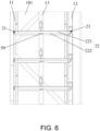
FIG. 6 is a schematic side view illustrating part of the structure of the energy storage frame shown inFIG. 2 . -
FIG. 7 is a schematic view illustrating the structure of an energy storage battery cluster of the invention. - The technical solutions in the exemplary embodiments of the disclosure will be described clearly and explicitly in conjunction with the drawings in the exemplary embodiments of the disclosure. The description proposed herein is just the exemplary embodiments for the purpose of illustrations only, not intended to limit the scope of the disclosure, so it should be understood that and various modifications and variations could be made thereto without departing from the scope of the disclosure.
- In the description of the present disclosure, unless otherwise specifically defined and limited, the terms "first", "second" and the like are only used for illustrative purposes and are not to be construed as expressing or implying a relative importance. The term "plurality" is two or more. The term "and/or" includes any and all combinations of one or more of the associated listed items.
- In particular, a reference to "the" object or "a" and "an" object is intended to denote also one of a possible plurality of such objects. Unless otherwise defined or described, the terms "connect", "fix" should be broadly interpreted, for example, the term "connect" can be "fixedly connect", "detachably connect", "integrally connect", "electrically connect" or "signal connect". The term "connect" also can be "directly connect" or "indirectly connect via a medium". For the persons skilled in the art, the specific meanings of the abovementioned terms in the present disclosure can be understood according to the specific situation.
- Further, in the description of the present disclosure, it should be understood that spatially relative terms, such as "above", "below" "inside", "outside" and the like, are described based on orientations illustrated in the figures, but are not intended to limit the exemplary embodiments of the present disclosure.
- In the context, it should also be understood that when an element or features is provided "outside" or "inside" of another element(s), it can be directly provided "outside" or "inside" of the other element, or be indirectly provided "outside" or "inside" of the another element(s) by an intermediate element.
- One object of the invention is to provide an energy storage frame capable of improving the connection stability between an insert box storage rack and a column.
- As shown in
FIG. 1 , the invention provides an energy storage frame including astand 10 and an insertbox storage rack 20. Specifically, thestand 10 is configured to fix the insertbox storage rack 20, the energy storage frame includes at least two stands 10 disposed opposite and apart from each other, and the twostands 10 are located on the left and right sides of the energy storage frame, respectively. Multiple insertbox storage racks 20 are connected between the two stands 10 and disposed at substantially equal intervals from top to bottom. Meanwhile, it can be applied that only one insertbox storage rack 20 is disposed to connect the twostands 10. - As shown in
FIG. 2 ,FIG. 4 , andFIG. 6 , thestand 10 includes afirst column 11 and asecond column 12 disposed side by side and at intervals. In the embodiment, specifically, thestand 10 includes anupright plate 101. Thefirst column 11 and thesecond column 12 are connected to one side of theupright plate 101 at intervals, theupright plate 101 can position and protect thefirst column 11 and thesecond column 12, both thefirst column 11 and thesecond column 12 extend in the vertical direction, and the bottom surface of thefirst column 11 and the bottom surface of thesecond column 12 both can be in contact with the ground or the plane where it is disposed. - The insert
box storage rack 20 is configured to support a battery insert box. When in use, the battery insert box can be inserted into the insertbox storage rack 20 from a side of the insertbox storage rack 20 that is not connected to thestand 10, and the battery insert box can be disposed within the insertbox storage rack 20. For the insertion direction of the battery insert box, refer to the direction indicated by the arrow W inFIG. 7 . As shown inFIG. 2 , the insertbox storage rack 20 is disposed on one side of thestand 10, and the insertbox storage rack 20 is disposed horizontally relative to thestand 10, that is, the insertbox storage rack 20 is disposed substantially parallel to the ground or the plane where it is disposed. The insertbox storage rack 20 includes a first connectingbeam 21 and a second connectingbeam 22. For example, the insertbox storage rack 20 is a rectangular frame structure formed by two first connectingbeams 21 and twosecond connecting beams 22, so as to stably support the battery insert box and minimize the overall weight of the insertbox storage rack 20; the first connectingbeam 21 is connected to thefirst column 11 along a first direction X, and the second connectingbeam 22 is connected to thesecond column 12 along a second direction Y. The first direction X is parallel to the insertion direction of the battery insert box, and the second direction Y is perpendicular to the insertion direction of the battery insert box, that is, the projections of the first direction X and the second direction Y on the horizontal plane are perpendicular to each other. Moreover, the horizontal plane is parallel to the cross section of thestand 10, that is, the projections of the first direction X and the second direction Y on the plane where the cross section of thestand 10 is located are perpendicular to each other. Such connection allows the insertbox storage rack 20 and thestand 10 to be fixed in two directions, which not only improves the connection strength between thestand 10 and the insertbox storage rack 20 but also greatly reduces the risk that the connection position may fail under the insertion force of the battery insert box because there is only one fixed direction between the two, and thus the configuration stability of the battery insert box is secured. - Note that in the embodiment shown in
FIG. 1 , the first connectingbeam 21 is a front beam of the insertbox storage rack 20, and the second connectingbeam 22 is a side beam of the insertbox storage rack 20. When in use, the battery insert box is inserted into the energy storage frame from the position of the front beam, the side beam is disposed parallel to the insertion direction of the battery insert box, and the first direction X is substantially perpendicular to the second direction Y. For example, the included angle of the projections of the first direction X and the second direction Y on the horizontal plane may range from 86° to 93°. - The energy storage frame of the invention, by fixing the connection between the insert
box storage rack 20 and thestand 10 in two directions, not only improves the connection strength between thestand 10 and the insertbox storage rack 20 but also reduces the risk of the connection position failure resulting from the influence of the insertion force of the battery insert box between thestand 10 and the insertbox storage rack 20, and thus the configuration stability of the battery insert box is secured. - Furthermore, when considering the battery insert box is inserted on the insert
box storage rack 20, and by the time the battery insert box is just inserted into the insertbox storage rack 20, the portion of the insertbox storage rack 20 first, in contact with the battery insert box, is subjected to a greater impact, and the portion of the insertbox storage rack 20, not in contact with the battery insert box, is basically not subjected to the impact at the time being. When the battery insert box is disposed in place, the portion of the insertbox storage rack 20, in contact with the battery insert box at last, is subjected to a relatively large impact, and the action direction of the impact is the same as the insertion direction of the battery insert box. To prevent the connection failure between the insertbox storage rack 20 and thestand 10 resulting from the action of the impact, as shown inFIG. 1 andFIG. 2 , along the insertion direction of the battery insert box, the insertbox storage rack 20 has aninsertion end 201 and alimit end 202 disposed opposite to each other. That is, the direction from theinsertion end 201 to thelimit end 202 is the insertion direction of the battery insert box. Theinsertion end 201 allows the battery insert box to pass through, thelimit end 202 is configured to abut against the battery insert box, thefirst column 11 is disposed at theinsertion end 201 of the insertbox storage rack 20, and thesecond column 12 is disposed at thelimit end 202 of the insertbox storage rack 20. That is, when the battery insert box is being inserted, the battery insert box may first pass through thefirst column 11 and move toward thesecond column 12 to complete the insertion action. Since the second connectingbeam 22 is connected to thesecond column 12 along a direction perpendicular to the insertion direction of the battery insert box, that is, the direction is perpendicular to the action direction of the impact, the connection is not likely to fail, and thus the configuration stability of the battery insert box in the energy storage frame is secured. - Furthermore, as shown in
FIG. 2 ,FIG. 4 , andFIG. 6 , thestand 10 further includes amiddle column 13 disposed between thefirst column 11 and thesecond column 12. Themiddle column 13 is connected to theupright plate 101, the number of themiddle column 13 can be one or plural, and the specific quantity can be set according to the actual use requirements. For example, for an energy storage frame requiring a larger volume and a higher load-bearing, multiplemiddle columns 13 at intervals are disposed and connected between thefirst column 11 and thesecond column 12; for an energy storage frame requiring a small volume and low load-bearing, it is applicable that simply onemiddle column 13 is disposed between thefirst column 11 and thesecond column 12 to ensure the use strength of thestand 10 and minimize the overall weight of the stand. The second connectingbeam 22 is connected to themiddle column 13 along the second direction Y, and the configuration of themiddle column 13 can not only increase the stability of thestand 10 but also improve the connection strength between thestand 10 and the insertbox storage rack 20, which further ensures the configuration stability of the battery insert box in the energy storage frame. - Furthermore, as shown in
FIG. 2 ,FIG. 4 , andFIG. 6 , thefirst column 11, thesecond column 12, and themiddle column 13 are disposed at equal intervals, that is, the columns in thestand 10 each are disposed at equal intervals. With such an architecture, each column can be subjected to the impact uniformly, thereby ensuring the service life of thestand 10. - Furthermore, as shown in
FIG. 2 andFIG. 3 , the first connectingbeam 21 includes asupport plate 211 and a connectingplate 212, thesupport plate 211 is configured to support the battery insert box, and the connectingplate 212 is connected to one side of thesupport plate 211 along the first direction X and disposed below thesupport plate 211. Specifically, the connectingplate 212 is connected to the front side of thesupport plate 211, that is, thesupport plate 211 faces toward one side of thefirst column 11; the connectingplate 212 is connected to thefirst column 11 through afirst connector 30, that is, the front side of the front beam is connected to thefirst column 11; and the first connectingbeam 21 is connected to thefirst column 11 through the connectingplate 212, so that the connection between the first connectingbeam 21 and thefirst column 11 is facilitated. In addition, the connectingplate 212 can strengthen thesupport plate 211 to improve the strength of thesupport plate 211. - The
first connector 30 is a bolt, a fixing pin, or a rivet. For example, a bolt is preferably used as thefirst connector 30 to facilitate the disassembly and assembly between the first connectingbeam 21 and thefirst column 11. - Note that the connecting
plate 212 and thefirst column 11 may also be connected by welding. - Furthermore, as shown in
FIG. 3 , alug 111 is disposed on one side wall of thefirst column 11, and thelug 111 is connected to the connectingplate 212 through thefirst connector 30. Specifically, thelug 111 is disposed on the side of thefirst column 11 adjacent to the insertbox storage rack 20, and thelug 111 and thefirst column 11 are integrally formed to ensure the connection strength between thelug 111 and thefirst column 11. The configuration of thelugs 111 not only increases the contact area between thefirst column 11 and the first connectingbeam 21 but also facilitates the connection between thefirst column 11 and the first connectingbeam 21. - Furthermore, the
support plate 211 and the connectingplate 212 are an integrated structure to ensure the overall strength of the first connectingbeam 21. Specifically, the first connectingbeam 21 is formed by bending sheet metal, that is, thesupport plate 211 and the connectingplate 212 are an integrated structure made of sheet metal material. Meanwhile, thesupport plate 211 and the connectingplate 212 may also be an integrated structure connected by welding. - Furthermore, as shown in
FIG. 6 , the second connectingbeam 22 includes atop plate 221 and aside plate 222. Thetop plate 221 is connected to the top end of theside plate 222, thetop plate 221 is configured to support the battery insert box, theside plate 222 is connected to thesecond column 12 through asecond connector 40, and theside plate 222 is connected to themiddle column 13 through athird connector 50. The configuration of theside plate 222 increases the contact area between the second connectingbeam 22 and themiddle column 13, thereby improving the connection strength between the second connectingbeam 22 and themiddle column 13 and facilitating the connection between the second connectingbeam 22 and themiddle column 13. - The
second connector 40 is a bolt, a fixing pin, or a rivet. For example, a bolt is preferably used as thesecond connector 40 to facilitate the disassembly and assembly between the second connectingbeam 22 and thesecond column 12. Thethird connector 50 is a bolt, a fixing pin, or a rivet. For example, a bolt is preferably used as thethird connector 50 to facilitate the disassembly and assembly between the second connectingbeam 22 and themiddle column 13. - Furthermore, the
top plate 221 and theside plate 222 are an integrated structure to ensure the overall strength of the second connectingbeam 22. Specifically, the second connectingbeam 22 is formed by bending sheet metal, that is, thetop plate 221 and theside plate 222 are an integrated structure made of sheet metal material. Meanwhile, thetop plate 221 and theside plate 222 may also be an integrated structure connected by welding. - Furthermore, to facilitate the insertion of the battery insert box, a polycarbonate (PC) board can be connected to the
top plate 221. The PC board has good wear resistance, and the surface is smoother, making it easier for the battery insert box to move to the insertbox storage rack 20. Specifically, the PC board is connected to thetop plate 221 by bolts to facilitate the disassembly and assembly of the PC board. - In one embodiment of the invention, as shown in
FIG. 1 ,FIG. 2 andFIG. 4 , the insert box storage rack further includes a third connectingbeam 23. The third connectingbeam 23 is configured to limit the battery insert box, the third connectingbeam 23 is disposed adjacent to thesecond column 12 and extends along the second direction Y, and the third connectingbeam 23 and the first connectingbeam 21 are connected to two ends of the second connectingbeam 22, respectively. For example, the insertbox storage rack 20 is a rectangular frame structure formed by one first connectingbeam 21, two second connectingbeams 22, and one third connectingbeam 23. The position of the first connectingbeam 21 is opposite to the position of the third connectingbeam 23, and the positions of the two second connectingbeams 22 are opposite to each other. - Specifically, as shown in
FIG. 4 andFIG. 5 , the third connectingbeam 23 includes an overlappingplate 231, areinforcement plate 232, and alimit plate 233. The overlappingplate 231 is configured to support the battery insert box, thereinforcement plate 232 is connected to one side of the overlappingplate 231 along the first direction X and disposed below the overlappingplate 231, and thelimit plate 233 is connected to another side of the overlappingplate 231 along the first direction X and is disposed above the overlappingplate 231. Specifically, thereinforcement plate 232 and thelimit plate 233 are connected to two sides of the overlappingplate 231, respectively, along the first direction X, and thereinforcement plate 232 and thelimit plate 233 are disposed at the upper and lower ends of the overlappingplate 231, respectively. Thereinforcement plate 232 can strengthen the overlappingplate 231 to improve the use strength of the overlappingplate 231, and thelimit plate 233 can abut against the battery insert box and prevent the battery insert box from being penetrated. - Furthermore, the overlapping
plate 231, thereinforcement plate 232, and thelimit plate 233 are an integrated structure to ensure the overall strength of the third connectingbeam 23. Specifically, the third connectingbeam 23 is formed by bending sheet metal, that is, the overlappingplate 231, thereinforcement plate 232, and thelimit plate 233 are an integrated structure made of sheet metal material. - Compared with the prior art, the technical solution has the following advantages: with the insert box storage rack and the stand, the energy storage frame of the invention is fixedly connected in two directions, which not only improves the connection strength between the stand and the insert box storage rack but also reduces the risk of the connection position failure resulting from the influence of the insertion force of the battery insert box between the stand and the insert box storage rack, and thus the configuration stability of the battery insert box in the energy storage frame is secured.
- Another object of the invention is to provide an energy storage battery cluster including the energy storage frame.
- As shown in
FIG. 7 , the invention further provides an energy storage battery cluster including theenergy storage frame 100 and at least onebattery insert box 200. Thebattery insert box 200 is inserted into theenergy storage frame 100, and the number of thebattery insert boxes 200 can be adjusted according to actual use requirements and the capacity of theenergy storage frame 100. - The energy storage battery cluster of the invention includes the energy storage frame and therefore has the advantages of stable structure and stable configuration of the battery insert box.
- In summary, with the insert box storage rack and the stand, the energy storage frame of the invention is fixedly connected in two directions, which not only improves the connection strength between the stand and the insert box storage rack but also reduces the risk of the connection position failure resulting from the influence of the insertion force of the battery insert box between the stand and the insert box storage rack, and thus the configuration stability of the battery insert box in the energy storage frame is secured;
- In the energy storage frame of the invention, with the configuration of a middle column and the connection between the side beams and the middle column, the stability of the stand can be increased, the connection strength between the stand and the insert box storage rack can be improved, and the configuration stability of the battery insert box in the energy storage frame is further secured.
- In the energy storage frame of the invention, the first connecting beam is connected to the first column through the first connector, the second connecting beam is connected to the second column through the second connector, and the side beam is connected to the middle column through the third connector, which facilitates the assembly and disassembly between the stand and the insert box storage rack, thereby saving time and efforts in the assembling operation of the energy storage frame.
- The energy storage battery cluster of the invention includes the energy storage frame and therefore has the advantages of stable structure and stable configuration of the battery insert box.
- Other embodiments of the disclosure will be apparent to those skilled in the art from consideration of the specification and practice of the disclosure disclosed herein. The disclosure is intended to cover any variations, uses or adaptations of the disclosure. These variations, uses, or adaptations follow the general principles of the disclosure and include common general knowledge or conventional technical means in the art that are not disclosed in the present disclosure.
Claims (10)
- An energy storage frame, comprising:a stand (10) comprising a first column (11) and a second column (12) disposed side by side and at intervals; andan insert box storage rack (20) configured to support a battery insert box, wherein the insert box storage rack (20) is disposed on one side of the stand (10), the insert box storage rack (20) comprises a first connecting beam (21) and a second connecting beam (22), the first connecting beam (21) is connected to the first column (11) along a first direction (X), the second connecting beam (22) is connected to the second column (12) along a second direction (Y), the first direction (X) is parallel to an insertion direction of the battery insert box, and the second direction (Y) is perpendicular to the insertion direction of the battery insert box.
- The energy storage frame according to claim 1, wherein
along the insertion direction of the battery insert box, the insert box storage rack (20) comprises an insertion end (201) and a limit end (202) disposed opposite to each other, the insertion end (201) allows the battery insert box to pass through, the limit end (202) is configured to abut against the battery insert box, the first column (11) is disposed at the insertion end (201) of the insert box storage rack (20), and the second column (12) is disposed at the limit end (202) of the insert box storage rack (20). - The energy storage frame according to claim 1 or claim 2, wherein
the stand (10) further comprises a middle column (13) disposed between the first column (11) and the second column (12), and the second connecting beam (22) is connected to the middle column (13) along the second direction (Y). - The energy storage frame according to claim 3, wherein
the first column (11), the second column (12), and the middle column (13) are disposed at equal intervals. - The energy storage frame according to claim 1, wherein
the first connecting beam (21) comprises a support plate (211) and a connecting plate (212), the connecting plate (212) is connected to one side of the support plate (211) along the first direction (X) and is disposed below the support plate (211), and the connecting plate (212) is connected to the first column (11) through a first connector (30). - The energy storage frame according to claim 5, wherein
a lug (111) is disposed on one side wall of the first column (11), and the lug (111) is connected to the connecting plate (212) through the first connector (30). - The energy storage frame according to claim 5, wherein
the support plate (211) and the connecting plate (212) are an integrated structure. - The energy storage frame according to claim 3, wherein
the second connecting beam (22) comprises a top plate (221) and a side plate (222), the top plate (221) is connected to a top end of the side plate (222), the side plate (222) is connected to the second column (12) through a second connector (40), and the side plate (222) is connected to the middle column (13) through a third connector (50). - The energy storage frame according to claim 8, wherein:
the top plate (221) and the side plate (222) are an integrated structure. - An energy storage battery cluster, comprising the energy storage frame according to any one of claims 1-9 and at least one battery insert box, and the battery insert box is inserted in the energy storage frame.
Applications Claiming Priority (1)
| Application Number | Priority Date | Filing Date | Title |
|---|---|---|---|
| CN202210299222.2A CN114614185A (en) | 2022-03-25 | 2022-03-25 | Energy storage frame and battery cluster |
Publications (2)
| Publication Number | Publication Date |
|---|---|
| EP4250446A2 true EP4250446A2 (en) | 2023-09-27 |
| EP4250446A3 EP4250446A3 (en) | 2023-12-27 |
Family
ID=81846234
Family Applications (1)
| Application Number | Title | Priority Date | Filing Date |
|---|---|---|---|
| EP22174979.9A Withdrawn EP4250446A3 (en) | 2022-03-25 | 2022-05-24 | Energy storage frame and energy storage battery cluster |
Country Status (3)
| Country | Link |
|---|---|
| US (1) | US20230307753A1 (en) |
| EP (1) | EP4250446A3 (en) |
| CN (1) | CN114614185A (en) |
Families Citing this family (2)
| Publication number | Priority date | Publication date | Assignee | Title |
|---|---|---|---|---|
| CN117438706A (en) * | 2022-07-15 | 2024-01-23 | 比亚迪股份有限公司 | Energy storage boxes and energy storage containers |
| WO2024065716A1 (en) * | 2022-09-30 | 2024-04-04 | 宁德时代新能源科技股份有限公司 | Energy storage box body and energy storage apparatus |
Family Cites Families (8)
| Publication number | Priority date | Publication date | Assignee | Title |
|---|---|---|---|---|
| JP3446701B2 (en) * | 1999-12-28 | 2003-09-16 | 株式会社ダイフク | Connecting rack |
| US20140134460A1 (en) * | 2012-11-13 | 2014-05-15 | Samsung Sdi Co., Ltd. | Energy storage system |
| JP2017073270A (en) * | 2015-10-07 | 2017-04-13 | 田淵電機株式会社 | Storage battery unit and storage battery housing device |
| US20170280875A1 (en) * | 2016-03-31 | 2017-10-05 | Whirlpool Corporation | Weldless support beam for rack shelving |
| KR102249488B1 (en) * | 2018-03-12 | 2021-05-06 | 주식회사 엘지화학 | An energy storage device with a hook structure and an energy storage system comprising the same |
| NO20200576A1 (en) * | 2019-05-24 | 2020-11-25 | Man Energy Solutions Se | Energy storage unit mounting facility and arrangement of the same and multiple energy storage unit |
| CN113381106A (en) * | 2021-06-10 | 2021-09-10 | 傲普(上海)新能源有限公司 | Battery pack capable of being simply installed and battery rack formed by battery pack |
| CN217035857U (en) * | 2022-03-25 | 2022-07-22 | 中创新航科技股份有限公司 | Energy storage frame and battery cluster |
-
2022
- 2022-03-25 CN CN202210299222.2A patent/CN114614185A/en active Pending
- 2022-05-18 US US17/746,977 patent/US20230307753A1/en active Pending
- 2022-05-24 EP EP22174979.9A patent/EP4250446A3/en not_active Withdrawn
Also Published As
| Publication number | Publication date |
|---|---|
| US20230307753A1 (en) | 2023-09-28 |
| CN114614185A (en) | 2022-06-10 |
| EP4250446A3 (en) | 2023-12-27 |
Similar Documents
| Publication | Publication Date | Title |
|---|---|---|
| EP4250446A2 (en) | Energy storage frame and energy storage battery cluster | |
| EP4250448A1 (en) | Energy storage rack | |
| CN115764132A (en) | Energy storage container | |
| US20230307755A1 (en) | Storage rack, energy storage frame, and energy storage battery cluster | |
| EP4345926A2 (en) | Battery shelf, energy storage frame, and energy storage battery cluster | |
| CN115863896B (en) | Battery bracket and energy storage device | |
| EP4615179A1 (en) | Power cabinet | |
| US20040069725A1 (en) | Seismically resistant network equipment rack | |
| EP4617150A1 (en) | Vehicle frame assembly, energy storage structure, and vehicle | |
| CN217035857U (en) | Energy storage frame and battery cluster | |
| US20230307765A1 (en) | Battery shelf, energy storage frame, and energy storage battery cluster | |
| KR20240051017A (en) | Battery rack and energy storage system comprising the same | |
| CN217589226U (en) | A battery rack and ship | |
| CN216930504U (en) | Novel antidetonation rack | |
| CN213184980U (en) | Low-voltage cabinet frame connecting device | |
| CN113097914B (en) | Handcart guide rail mounting structure of nuclear power switch cabinet | |
| CN223502094U (en) | A guide rail tray and cabinet frame for battery modules | |
| CN219371810U (en) | Vibration-resistant cabinet base structure | |
| CN219226954U (en) | Energy storage cabinet frame, energy storage cabinet and power distribution equipment | |
| CN217228894U (en) | Connecting device for goods shelf and steel platform | |
| CN210959207U (en) | Cabinet capable of resisting vibration | |
| CN222940088U (en) | CTP box reinforcement beam installation structure | |
| CN222507859U (en) | Battery cluster frame, movable energy storage container and movable energy storage vehicle | |
| EP4481914A1 (en) | Rack assembly and battery pack including the same | |
| CN224082974U (en) | A modular precision cabinet |
Legal Events
| Date | Code | Title | Description |
|---|---|---|---|
| PUAI | Public reference made under article 153(3) epc to a published international application that has entered the european phase |
Free format text: ORIGINAL CODE: 0009012 |
|
| STAA | Information on the status of an ep patent application or granted ep patent |
Free format text: STATUS: REQUEST FOR EXAMINATION WAS MADE |
|
| 17P | Request for examination filed |
Effective date: 20220524 |
|
| AK | Designated contracting states |
Kind code of ref document: A2 Designated state(s): AL AT BE BG CH CY CZ DE DK EE ES FI FR GB GR HR HU IE IS IT LI LT LU LV MC MK MT NL NO PL PT RO RS SE SI SK SM TR |
|
| PUAL | Search report despatched |
Free format text: ORIGINAL CODE: 0009013 |
|
| AK | Designated contracting states |
Kind code of ref document: A3 Designated state(s): AL AT BE BG CH CY CZ DE DK EE ES FI FR GB GR HR HU IE IS IT LI LT LU LV MC MK MT NL NO PL PT RO RS SE SI SK SM TR |
|
| RIC1 | Information provided on ipc code assigned before grant |
Ipc: H01M 50/289 20210101ALI20231122BHEP Ipc: H01M 50/251 20210101ALI20231122BHEP Ipc: H01M 50/244 20210101ALI20231122BHEP Ipc: H01M 50/233 20210101ALI20231122BHEP Ipc: H01M 50/204 20210101AFI20231122BHEP |
|
| STAA | Information on the status of an ep patent application or granted ep patent |
Free format text: STATUS: THE APPLICATION IS DEEMED TO BE WITHDRAWN |
|
| 18D | Application deemed to be withdrawn |
Effective date: 20240628 |