EP4250432A1 - Battery module and battery pack including same - Google Patents
Battery module and battery pack including same Download PDFInfo
- Publication number
- EP4250432A1 EP4250432A1 EP22898785.5A EP22898785A EP4250432A1 EP 4250432 A1 EP4250432 A1 EP 4250432A1 EP 22898785 A EP22898785 A EP 22898785A EP 4250432 A1 EP4250432 A1 EP 4250432A1
- Authority
- EP
- European Patent Office
- Prior art keywords
- bus bar
- battery
- battery module
- neutralizer
- battery cell
- Prior art date
- Legal status (The legal status is an assumption and is not a legal conclusion. Google has not performed a legal analysis and makes no representation as to the accuracy of the status listed.)
- Granted
Links
Images




Classifications
-
- H—ELECTRICITY
- H01—ELECTRIC ELEMENTS
- H01M—PROCESSES OR MEANS, e.g. BATTERIES, FOR THE DIRECT CONVERSION OF CHEMICAL ENERGY INTO ELECTRICAL ENERGY
- H01M10/00—Secondary cells; Manufacture thereof
- H01M10/42—Methods or arrangements for servicing or maintenance of secondary cells or secondary half-cells
- H01M10/48—Accumulators combined with arrangements for measuring, testing or indicating the condition of cells, e.g. the level or density of the electrolyte
- H01M10/482—Accumulators combined with arrangements for measuring, testing or indicating the condition of cells, e.g. the level or density of the electrolyte for several batteries or cells simultaneously or sequentially
-
- H—ELECTRICITY
- H01—ELECTRIC ELEMENTS
- H01M—PROCESSES OR MEANS, e.g. BATTERIES, FOR THE DIRECT CONVERSION OF CHEMICAL ENERGY INTO ELECTRICAL ENERGY
- H01M10/00—Secondary cells; Manufacture thereof
- H01M10/42—Methods or arrangements for servicing or maintenance of secondary cells or secondary half-cells
-
- G—PHYSICS
- G01—MEASURING; TESTING
- G01M—TESTING STATIC OR DYNAMIC BALANCE OF MACHINES OR STRUCTURES; TESTING OF STRUCTURES OR APPARATUS, NOT OTHERWISE PROVIDED FOR
- G01M3/00—Investigating fluid-tightness of structures
- G01M3/02—Investigating fluid-tightness of structures by using fluid or vacuum
- G01M3/04—Investigating fluid-tightness of structures by using fluid or vacuum by detecting the presence of fluid at the leakage point
-
- G—PHYSICS
- G01—MEASURING; TESTING
- G01N—INVESTIGATING OR ANALYSING MATERIALS BY DETERMINING THEIR CHEMICAL OR PHYSICAL PROPERTIES
- G01N33/00—Investigating or analysing materials by specific methods not covered by groups G01N1/00 - G01N31/00
- G01N33/0004—Gaseous mixtures, e.g. polluted air
- G01N33/0009—General constructional details of gas analysers, e.g. portable test equipment
- G01N33/0027—General constructional details of gas analysers, e.g. portable test equipment concerning the detector
- G01N33/0036—General constructional details of gas analysers, e.g. portable test equipment concerning the detector specially adapted to detect a particular component
- G01N33/0044—Sulphides, e.g. H2S
-
- H—ELECTRICITY
- H01—ELECTRIC ELEMENTS
- H01M—PROCESSES OR MEANS, e.g. BATTERIES, FOR THE DIRECT CONVERSION OF CHEMICAL ENERGY INTO ELECTRICAL ENERGY
- H01M10/00—Secondary cells; Manufacture thereof
- H01M10/42—Methods or arrangements for servicing or maintenance of secondary cells or secondary half-cells
- H01M10/48—Accumulators combined with arrangements for measuring, testing or indicating the condition of cells, e.g. the level or density of the electrolyte
-
- H—ELECTRICITY
- H01—ELECTRIC ELEMENTS
- H01M—PROCESSES OR MEANS, e.g. BATTERIES, FOR THE DIRECT CONVERSION OF CHEMICAL ENERGY INTO ELECTRICAL ENERGY
- H01M50/00—Constructional details or processes of manufacture of the non-active parts of electrochemical cells other than fuel cells, e.g. hybrid cells
- H01M50/20—Mountings; Secondary casings or frames; Racks, modules or packs; Suspension devices; Shock absorbers; Transport or carrying devices; Holders
- H01M50/204—Racks, modules or packs for multiple batteries or multiple cells
- H01M50/207—Racks, modules or packs for multiple batteries or multiple cells characterised by their shape
- H01M50/209—Racks, modules or packs for multiple batteries or multiple cells characterised by their shape adapted for prismatic or rectangular cells
-
- H—ELECTRICITY
- H01—ELECTRIC ELEMENTS
- H01M—PROCESSES OR MEANS, e.g. BATTERIES, FOR THE DIRECT CONVERSION OF CHEMICAL ENERGY INTO ELECTRICAL ENERGY
- H01M50/00—Constructional details or processes of manufacture of the non-active parts of electrochemical cells other than fuel cells, e.g. hybrid cells
- H01M50/20—Mountings; Secondary casings or frames; Racks, modules or packs; Suspension devices; Shock absorbers; Transport or carrying devices; Holders
- H01M50/204—Racks, modules or packs for multiple batteries or multiple cells
- H01M50/207—Racks, modules or packs for multiple batteries or multiple cells characterised by their shape
- H01M50/211—Racks, modules or packs for multiple batteries or multiple cells characterised by their shape adapted for pouch cells
-
- H—ELECTRICITY
- H01—ELECTRIC ELEMENTS
- H01M—PROCESSES OR MEANS, e.g. BATTERIES, FOR THE DIRECT CONVERSION OF CHEMICAL ENERGY INTO ELECTRICAL ENERGY
- H01M50/00—Constructional details or processes of manufacture of the non-active parts of electrochemical cells other than fuel cells, e.g. hybrid cells
- H01M50/20—Mountings; Secondary casings or frames; Racks, modules or packs; Suspension devices; Shock absorbers; Transport or carrying devices; Holders
- H01M50/271—Lids or covers for the racks or secondary casings
-
- H—ELECTRICITY
- H01—ELECTRIC ELEMENTS
- H01M—PROCESSES OR MEANS, e.g. BATTERIES, FOR THE DIRECT CONVERSION OF CHEMICAL ENERGY INTO ELECTRICAL ENERGY
- H01M50/00—Constructional details or processes of manufacture of the non-active parts of electrochemical cells other than fuel cells, e.g. hybrid cells
- H01M50/20—Mountings; Secondary casings or frames; Racks, modules or packs; Suspension devices; Shock absorbers; Transport or carrying devices; Holders
- H01M50/296—Mountings; Secondary casings or frames; Racks, modules or packs; Suspension devices; Shock absorbers; Transport or carrying devices; Holders characterised by terminals of battery packs
-
- H—ELECTRICITY
- H01—ELECTRIC ELEMENTS
- H01M—PROCESSES OR MEANS, e.g. BATTERIES, FOR THE DIRECT CONVERSION OF CHEMICAL ENERGY INTO ELECTRICAL ENERGY
- H01M50/00—Constructional details or processes of manufacture of the non-active parts of electrochemical cells other than fuel cells, e.g. hybrid cells
- H01M50/50—Current conducting connections for cells or batteries
- H01M50/502—Interconnectors for connecting terminals of adjacent batteries; Interconnectors for connecting cells outside a battery casing
- H01M50/507—Interconnectors for connecting terminals of adjacent batteries; Interconnectors for connecting cells outside a battery casing comprising an arrangement of two or more busbars within a container structure, e.g. busbar modules
-
- H—ELECTRICITY
- H01—ELECTRIC ELEMENTS
- H01M—PROCESSES OR MEANS, e.g. BATTERIES, FOR THE DIRECT CONVERSION OF CHEMICAL ENERGY INTO ELECTRICAL ENERGY
- H01M50/00—Constructional details or processes of manufacture of the non-active parts of electrochemical cells other than fuel cells, e.g. hybrid cells
- H01M50/50—Current conducting connections for cells or batteries
- H01M50/543—Terminals
- H01M50/552—Terminals characterised by their shape
- H01M50/553—Terminals adapted for prismatic, pouch or rectangular cells
-
- H—ELECTRICITY
- H01—ELECTRIC ELEMENTS
- H01M—PROCESSES OR MEANS, e.g. BATTERIES, FOR THE DIRECT CONVERSION OF CHEMICAL ENERGY INTO ELECTRICAL ENERGY
- H01M50/00—Constructional details or processes of manufacture of the non-active parts of electrochemical cells other than fuel cells, e.g. hybrid cells
- H01M50/50—Current conducting connections for cells or batteries
- H01M50/569—Constructional details of current conducting connections for detecting conditions inside cells or batteries, e.g. details of voltage sensing terminals
-
- H—ELECTRICITY
- H01—ELECTRIC ELEMENTS
- H01M—PROCESSES OR MEANS, e.g. BATTERIES, FOR THE DIRECT CONVERSION OF CHEMICAL ENERGY INTO ELECTRICAL ENERGY
- H01M2220/00—Batteries for particular applications
- H01M2220/20—Batteries in motive systems, e.g. vehicle, ship, plane
-
- Y—GENERAL TAGGING OF NEW TECHNOLOGICAL DEVELOPMENTS; GENERAL TAGGING OF CROSS-SECTIONAL TECHNOLOGIES SPANNING OVER SEVERAL SECTIONS OF THE IPC; TECHNICAL SUBJECTS COVERED BY FORMER USPC CROSS-REFERENCE ART COLLECTIONS [XRACs] AND DIGESTS
- Y02—TECHNOLOGIES OR APPLICATIONS FOR MITIGATION OR ADAPTATION AGAINST CLIMATE CHANGE
- Y02E—REDUCTION OF GREENHOUSE GAS [GHG] EMISSIONS, RELATED TO ENERGY GENERATION, TRANSMISSION OR DISTRIBUTION
- Y02E60/00—Enabling technologies; Technologies with a potential or indirect contribution to GHG emissions mitigation
- Y02E60/10—Energy storage using batteries
Definitions
- the present disclosure relates to a battery module and a battery pack including the same, and more particularly to a battery module having enhanced safety and a battery pack including the same.
- a secondary battery has attracted considerable attention as an energy source for power-driven devices, such as an electric bicycle, an electric vehicle, and a hybrid electric vehicle, as well as an energy source for mobile devices, such as a mobile phone, a digital camera, a laptop computer and a wearable device.
- a middle or large-sized battery module having a plurality of battery cells electrically connected to one another is used.
- middle or large-sized battery modules are preferably manufactured with as small a size and weight as possible, a prismatic battery, a pouch-type battery, or the like, which can be stacked with high integration and has a small weight relative to capacity, is mainly used as a battery cell of the middle or large-sized battery modules.
- a battery module has a structure in which a plurality of cell assemblies including a plurality of unit battery cells are connected in series to obtain high output.
- the battery cell includes positive and negative electrode current collectors, a separator, an active material, an electrolyte, and the like, and thus can be repeatedly charged and discharged through an electrochemical reaction between components.
- the all-solid-state battery is a battery that utilizes a solid electrolyte instead of the liquid electrolyte, and has an advantage of having higher thermal stability than the existing lithium secondary battery using a liquid electrolyte.
- the all-solid-state battery is more advantageous than a conventional lithium secondary battery in terms of high energy density and output characteristics, simplification of the manufacturing process and enlargement/compactness of a battery.
- a sulfide-based all-solid-state battery using a sulfide-based electrolyte has the characteristics of being relatively inexpensive and safe, but when the sulfide-based electrolyte is exposed to moisture, there is a risk of generating hydrogen sulfide (H 2 S), which is a hazardous material.
- a battery module comprising: a battery cell stack in which a plurality of battery cells are stacked, a module frame that surrounds the battery cell stack, a bus bar frame that covers the portion of the battery cell stack exposed from the module frame, a bus bar that is connected to an electrode lead protruding from the battery cell stack through the bus bar frame, a gas sensor formed on the bus bar frame, a bus bar cover portion that covers the bus bar, and a neutralizer housing portion formed on the bus bar cover portion.
- the gas sensor may be formed to be adjacent to the bus bar.
- the bus bar comprises a terminal bus bar, and the gas sensor may be formed to be adjacent to the terminal of the terminal bus bar.
- the bus bar cover portion may cover the terminal of the terminal bus bar.
- the battery module according to another embodiment of the present disclosure further comprises an end plate that covers the bus bar frame, and may further comprise a gas sensor formed on the end plate.
- the battery module according to yet another embodiment of the present disclosure further comprises a gas sensor formed between an upper part of the battery cell stack and the module frame.
- the battery module may further comprise a neutralizer formed inside the neutralizer housing portion.
- the neutralizer may comprise at least one component selected from the group comprising an iron compound and a catalyst.
- the neutralizer housing portion may comprise at least one kind of shapes selected from the group comprising a pad, a pocket, an aerosol, and a bulb.
- the battery module may further comprise a neutralizer injection portion formed in the neutralizer housing portion.
- a battery pack comprising the above-mentioned battery module.
- a battery module includes a gas sensor that can detect leakage of hydrogen sulfide and a neutralizer housing portion that can neutralize hydrogen sulfide, whereby during leakage of hydrogen sulfide, it is possible to detect and neutralize this to improve the safety of the battery module and battery pack.
- planar it means when a target portion is viewed from the upper side
- cross-sectional it means when a target portion is viewed from the side of a cross section cut vertically.
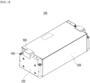
- Fig. 1 is a perspective view showing a battery module according to one embodiment of the present disclosure.
- Fig. 2 is a perspective view showing a state in which all the components of Fig. 1 are combined.
- Fig. 3 is an exploded perspective view showing some of the components of Fig. 1 .
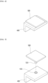
- Fig. 6 is a perspective view showing a bus bar cover portion and a neutralizer housing portion included in the battery module of the present disclosure.
- Fig. 7 is a perspective view showing another shape of a bus bar cover portion and a neutralizer housing portion included in the battery module of the present disclosure.
- Fig. 8 is a perspective view showing a battery cell included in the battery module of the present disclosure.
- a battery module 100 includes a battery cell stack 120 in which a plurality of battery cells 110 are stacked, and a module frame 200 that surrounds the battery cell stack 120.
- the battery cell 110 is preferably a pouch-type battery cell, and can be formed in a rectangular sheet-like structure.
- the battery cell 110 according to the present embodiment has a structure in which two electrode leads 111 and 112 face each other and protrude from one end part 114a and the other end part 114b of the cell main body 113, respectively. That is, the battery cell 110 includes electrode leads 111 and 112 that are protruded in mutually opposite directions. More specifically, the electrode leads 111 and 112 are connected to an electrode assembly (not shown), and are protruded from the electrode assembly (not shown) to the outside of the battery cell 110. However, unlike those shown in Fig. 8 , the two electrode leads 111 and 112 may have a structure protruding from one side surface of the same battery cell 110. Therefore, the two electrode leads 111 and 112 may protrude in the same direction.
- the battery cell 110 can be produced by joining both end parts 114a and 114b of a cell case 114 and one side part 114c connecting them in a state in which an electrode assembly (not shown) is housed in a cell case 114.
- the battery cell 110 according to the present embodiment has a total of three sealing parts 114sa, 114sb and 114sc, wherein the sealing parts 114sa, 114sb and 114sc have a structure that is sealed by a method such as heat-sealing, and the remaining other side part may be composed of a connection part 115.
- the sealing parts 114sa, 114sb and 114sc may include a sealing part 114sc formed in the longitudinal direction of the battery cell, and a sealing parts 114sa and 114sb formed in the width direction of the battery cell.
- the battery cell may have four sealing parts by further including one sealing part formed in the longitudinal direction of the battery cell together with the three sealing parts 114sa, 114sb and 114sc.
- the cell case 114 may be formed of a laminated sheet including a resin layer and a metal layer.
- both ends 114a and 114b of the battery case 114 may be defined as the longitudinal direction of the battery cell 110, and between one side part 114c connecting both ends 114a and 114b of the battery case 114 and the connection part 115 may be defined as a width direction of the battery cell 110.
- connection part 115 may extend long along one edge of the battery cell 110, and a bat-ear 110p may be formed at an end of the connection part 115.
- a terrace part 116 may be formed between the electrode leads 111 and 112 and the cell main body 113. That is, the battery cell 110 may include a terrace part 116 formed to extend from the cell case 114 in the direction in which the electrode leads 111 and 112 protrude.
- Such a battery cell 110 may be composed by a plurality of numbers, and the plurality of battery cells 110 may be stacked so as to be electrically connected to each other, thereby forming a battery cell stack 120. Particularly, as shown in Fig. 3 , a plurality of battery cells 110 may be stacked along the direction parallel to the y-axis. Thereby, the electrode leads 111 and 112 may protrude in the x-axis direction and the -x-axis direction, respectively. However, as described above, in the battery cell 110 in which the electrode leads 111 and 112 protrude in the same direction, the two electrode leads 111 and 112 may protrude equally in the x-axis direction or in the -x-axis direction.
- the module frames 200 may be a mono frame that surrounds the battery cell stack 120 excluding the front and rear surfaces thereof.
- the module frame 200 is not limited thereto, and may include a module frame structure that includes an L-shaped frame or a U-shaped frame which is opened in the upper surface, the front surface and the rear surface thereof and covers the lower part and both side parts of the battery cell stack 120, and an upper plate that covers an upper part of the battery cell stack 120.
- the battery cell stack 120 housed inside the module frame 200 can be physically protected through the module frame 200.
- the battery module 100 may further include a thermal conductive resin layer located between the lower surface of the battery cell stack 120 and the bottom part of the module frame 200, and the thermal conductive resin layer can play a role of transferring heat generated in the battery cell 110 to the bottom of the battery module 100 and fixing the battery cell stack 120.
- a cooling flow path or an additional heat dissipation material formed to contact the lower surface of the battery cell stack 120 is formed, thereby enabling surface cooling of the battery cell stack 120.
- the end plate 150 may cover the front and rear surfaces of the battery cell stack 120 that are opened in the module frame 200.
- the end plate 150 may be weld-coupled to the front and rear end edges of the module frame 200.
- a bus bar frame 130 may be formed between the end plate 150 and the front and rear surfaces of the battery cell stack 120. That is, the end plate 150 may cover the bus bar frame 130. At this time, the bus bar frame 130 may cover the portion of the battery cell stack 120 exposed from the module frame 200.
- the plurality of bus bars 140 mounted to the bus bar frame 130 are formed to protrude from the battery cells 110 through the bus bar frame 130, and can be connected with the electrode leads 111 and 112 mounted to the bus bar frame 130.
- the bus bar 140 may include a terminal bus bar 141
- the terminal bus bar 141 may include a terminal 141a.
- the battery module according to the present embodiment may include a bus bar cover portion 400 that covers the portion where the bus bar 140, particularly the terminal bus bar 141, is exposed to the outside of the end plate 150.
- the bus bar cover portion 400 is formed so as to cover the terminal 141a of the terminal bus bar 141, so that the terminal 141a can be prevented from being exposed to the outside of the battery module 100. Further, as will be described later, it can play a role of temporarily preventing leakage of hydrogen sulfide, which is highly likely to flow out from the terminal 141a.
- a sulfide-based all-solid-state battery using a sulfide-based electrolyte has a risk of generating hydrogen sulfide (H 2 S), which is a hazardous material, when the sulfide-based electrolyte is exposed to moisture.
- H 2 S hydrogen sulfide
- the battery module according to the present embodiment includes a gas sensor 300 formed on the bus bar frame 130, a bus bar cover portion 400 covering the bus bar 140, and a neutralizer housing portion 500 formed on the bus bar cover portion 400.
- the gas sensor 300 may be formed on the bus bar frame 130 so as to be adjacent to the bus bar 140.
- the gas sensor 300 may be formed to be adjacent to the bus bar 140. More specifically, the gas sensor 300 is formed to be adjacent to the terminal 141a of the terminal bus bar 141, so that the effect of immediately detecting hydrogen sulfide leakage can be achieved.
- the battery module 100 includes the neutralizer housing portion 500 formed on the bus bar cover portion 400 as described above.
- the neutralizer housing portion 500 may be formed to be adjacent to the terminal 141a of the terminal bus bar 141 with a high risk of hydrogen sulfide leakage in order to immediately remove the hydrogen sulfide after the gas sensor 300 detects the leakage of hydrogen sulfide.
- the neutralizer housing portion 500 may be formed on the bus bar cover portion 400 that covers the terminal 141a of the terminal bus bar 141.
- the neutralizer housing portion 500 may include a neutralizer formed inside the neutralizer housing portion 500.
- the neutralizer may include at least one component selected from the group comprising iron compounds and catalysts.
- the iron compound may include ferric sulfate (Fe 2 (SO 4 ) 3 ), iron(III) oxide (Fe 2 O 3 ), iron oxyhydroxide (FeO(OH)) and/or iron citrate (FeC 6 H 5 O 7 ).
- the catalyst may include iron hydroxide (Fe(OH) 2 , Fe(OH) 3 ) and/or zinc hydroxide. Therefore, the neutralizer may include one or more components selected from the group comprising the iron compound and the catalyst, and hydrogen sulfide can be neutralized through the above component.
- the neutralizer housing portion 500 may include at least one kind of shapes selected from the group comprising a pad, a pocket, an aerosol, and a bulb.
- the neutralizer housing portion 500 includes the pad shape, so that the neutralizer is stored in the form of microcapsules inside the pad shape, and hydrogen sulfide is neutralized by the neutralizer.
- the pad-shaped neutralizer housing portion 500 allows hydrogen sulfide and the neutralizer to react inside the pad while hydrogen sulfide passes through the pad.
- the pocket shape may form a pocket of a polymeric material and/or a metallic material, and house the neutralizer therein. Therefore, during generation of hydrogen sulfide, the pocket is crushed and the neutralizer leaks to the outside to react with hydrogen sulfide.
- the pad shape and the pocket shape may be formed on the bus bar cover portion 400 as shown in Fig. 6 .
- the neutralizer housing portion 500 may include an aerosol fire extinguishing shape that injects the neutralizer into the air in the form of an aerosol.
- the aerosol-shaped neutralizer housing portion 500 may include a neutralizer injection portion 510 formed under the neutralizer housing portion 500.
- a hole 410 may be formed on the bus bar cover 400 to minimize the protruding portion of the neutralizer injection portion 510.
- the neutralizer injection portion 510 can be formed to be coupled to the hole 410, and when hydrogen sulfide flows out, the neutralizer may be injected over a wide area through the neutralizer injection portion 510 to neutralize hydrogen sulfide.
- the bulb shape may specifically include a plastic bulb shape.
- the bulb shape may include a neutralizer housing portion 500 and a neutralizer injection portion 510 as shown in Fig. 7 , and in some cases, it may further include a liquid formed in the neutralizer injection portion 510. Therefore, when the battery module 100 generates heat, a liquid may evaporate to open the neutralizer injection portion 510, or in some cases, the bulb-shaped neutralizer housing portion 500 is crushed to neutralize hydrogen sulfide.
- the neutralizer housing portion 500 including the above shape may be formed into the shape of a rectangular parallelepiped or a hexahedron with rounded corners so as to be formed on the bus bar cover portion 400.
- the neutralizer housing portion 500 of the present disclosure can be formed in various shapes within a range that can secure the neutralization performance of the neutralizer housing portion.
- the neutralizer housing portion 500 includes the above shape, and the neutralizer is housed inside the neutralizer housing portion 500, whereby when leakage of hydrogen sulfide is detected by a gas sensor 300, the neutralizer housing portion 500 is opened to inject the neutralizer, thereby neutralizing hydrogen sulfide. Further, by securing a structure that can neutralize hydrogen sulfide, which is a hazardous material, when it leaks, the safety of the battery module 100, the battery pack including the battery module 100 and the device can be improved.
- This embodiment may include all contents related to the battery module described above, and only the contents that do not overlap with those described above will be described.
- Fig. 4 is an exploded perspective view showing some of the components of the battery module according to another embodiment of the present disclosure.
- Fig. 5 is a diagram showing a battery module according to another embodiment of the present disclosure.
- the battery module 100 may further include a gas sensor 310 formed on the end plate 150.
- the gas sensor 310 may be formed to be adjacent to the terminal 141a of the terminal bus bar 141. Therefore, the gas sensor 310 is formed on the inner surface or the outer surface of the end plate 150 adjacent to the terminal 141a, so that generation and leakage of hydrogen sulfide can be immediately detected through the gas sensor 310.
- the battery module according to the present embodiment may further include a gas sensor 320 that is formed between an upper part of the battery cell stack 120 and the module frame 200.
- the gas sensor 320 may be formed between the upper part of the battery cell stack 120 adj acent to the terminal 141a of the terminal bus bar 141 and the upper part of the module frame 200.
- the gas sensor 320 may be formed on the inner surface of the upper part of the module frame 200, and may be formed on the upper part of the battery cell stack 120.
- Leakage of hydrogen sulfide can be detected through the gas sensor 320 formed at the position to immediately neutralize hydrogen sulfide.
- the gas sensors 300, 310 and 320 can be formed in at least one position selected from between the bus bar frame 130 and the terminal 141a, between the end plate 150 and the terminal 141a, and between the battery cell stack 120 and the module frame 200. Therefore, not only a case where the gas sensors are formed in all positions where the above-mentioned gas sensors 300, 310 and 320 can be formed, but also a case where a gas sensor is formed in a part of the formable positions can be included in the scope of the present disclosure.
- one or a plurality of gas sensors 300 are formed to be adjacent to the terminal 141a of the bus bar 140, particularly, the terminal bus bar 141 as described above, so that leakage of hydrogen sulfide can be detected.
- the neutralizer housing portion 500 is formed to be adjacent to the leakage position of the hydrogen sulfide, thereby detecting the leakage of hydrogen sulfide and at the same time, injecting the neutralizer to neutralize hydrogen sulfide. Therefore, it is possible to prevent the safety of the battery module 100 from being deteriorated due to the leakage of hydrogen sulfide, and furthermore, to secure the safety of the battery pack and the device in which the battery module 100 is arranged.
- a battery pack according to yet another embodiment of the present invention will be described below.
- the battery pack according to the present embodiment includes the battery module described above.
- the battery pack of the present disclosure may have a structure in which one or more of the battery modules according to the present embodiment are gathered, and packed together with a battery management system (BMS) and a cooling device that control and manage battery's temperature, voltage, etc.
- BMS battery management system
- the battery pack can be applied to various devices.
- a device can be applied to a vehicle means such as an electric bicycle, an electric vehicle, or a hybrid vehicle, but the present disclosure is not limited thereto, and is applicable to various devices that can use a battery module, which is also falls under the scope of the present disclosure.
- Fig. 9 is a schematic diagram of a hydrogen sulfide neutralization system operating in a battery pack and a device including the battery pack according to yet another embodiment of the present disclosure.
- the battery pack and device including the battery module of the present disclosure may further include a step of detecting hydrogen sulfide leakage through a gas sensor, and a step of grasping the leaked hydrogen sulfide concentration.
- a step of opening the neutralizer housing portion 500 to inject the neutralizer may be further included.
- a step of notifying the user of the neutralizer injection may be further included.
- the gas sensors 300,310 and 320 and the neutralizer housing portion 500 included in the battery module 100 described in the present embodiments can constitute a neutralization system of hydrogen sulfide through the configuration of the slave BMS, BMS and instrument panel included in the battery pack and device. That is, the battery pack and device according to the present embodiment include a hydrogen sulfide neutralization system comprising the steps of grasping the degree of leakage of hydrogen sulfide detected through the gas sensor, opening the neutralizer housing portion 500, and notifying the user of this, thereby capable of securing more improved safety.
Landscapes
- Chemical & Material Sciences (AREA)
- Chemical Kinetics & Catalysis (AREA)
- Electrochemistry (AREA)
- General Chemical & Material Sciences (AREA)
- Engineering & Computer Science (AREA)
- Manufacturing & Machinery (AREA)
- Life Sciences & Earth Sciences (AREA)
- Health & Medical Sciences (AREA)
- General Physics & Mathematics (AREA)
- Physics & Mathematics (AREA)
- Food Science & Technology (AREA)
- Medicinal Chemistry (AREA)
- Analytical Chemistry (AREA)
- Biochemistry (AREA)
- General Health & Medical Sciences (AREA)
- Combustion & Propulsion (AREA)
- Immunology (AREA)
- Pathology (AREA)
- Battery Mounting, Suspending (AREA)
- Connection Of Batteries Or Terminals (AREA)
Abstract
Description
- This application claims the benefit of
Korean Patent Application No. 10-2021-0163384 filed on November 24, 2021 - The present disclosure relates to a battery module and a battery pack including the same, and more particularly to a battery module having enhanced safety and a battery pack including the same.
- With the technology development and increased demand for mobile devices, demand for secondary batteries as energy sources has been rapidly increasing. In particular, a secondary battery has attracted considerable attention as an energy source for power-driven devices, such as an electric bicycle, an electric vehicle, and a hybrid electric vehicle, as well as an energy source for mobile devices, such as a mobile phone, a digital camera, a laptop computer and a wearable device.
- In small mobile devices, one, or two, or three battery cells are used per device, while middle or large-sized devices such as vehicles require high power and large capacity. Therefore, a middle or large-sized battery module having a plurality of battery cells electrically connected to one another is used.
- Since middle or large-sized battery modules are preferably manufactured with as small a size and weight as possible, a prismatic battery, a pouch-type battery, or the like, which can be stacked with high integration and has a small weight relative to capacity, is mainly used as a battery cell of the middle or large-sized battery modules. Such a battery module has a structure in which a plurality of cell assemblies including a plurality of unit battery cells are connected in series to obtain high output. And, the battery cell includes positive and negative electrode current collectors, a separator, an active material, an electrolyte, and the like, and thus can be repeatedly charged and discharged through an electrochemical reaction between components.
- At this time, an all-solid-state battery using the above-mentioned electrolyte as an all-solid material is being developed, but the all-solid-state battery is a battery that utilizes a solid electrolyte instead of the liquid electrolyte, and has an advantage of having higher thermal stability than the existing lithium secondary battery using a liquid electrolyte. In addition, the all-solid-state battery is more advantageous than a conventional lithium secondary battery in terms of high energy density and output characteristics, simplification of the manufacturing process and enlargement/compactness of a battery. Thus, recently, research and interest have been focused on these points.
- Particularly, among all-solid-state batteries, a sulfide-based all-solid-state battery using a sulfide-based electrolyte has the characteristics of being relatively inexpensive and safe, but when the sulfide-based electrolyte is exposed to moisture, there is a risk of generating hydrogen sulfide (H2S), which is a hazardous material.
- Therefore, even when hydrogen sulfide is generated, there is a need for a new technology that can neutralize hydrogen sulfide so that hydrogen sulfide does not leak outside the battery module and the battery pack.
- It is an object of the present disclosure to provide a battery module having enhanced safety, and a battery pack including the same.
- However, the objects of the present disclosure are not limited to the aforementioned objects, and other objects which are not mentioned herein should be clearly understood by those skilled in the art from the following detailed description and the accompanying drawings.
- According to one embodiment of the present disclosure, there is provided a battery module comprising: a battery cell stack in which a plurality of battery cells are stacked, a module frame that surrounds the battery cell stack, a bus bar frame that covers the portion of the battery cell stack exposed from the module frame, a bus bar that is connected to an electrode lead protruding from the battery cell stack through the bus bar frame, a gas sensor formed on the bus bar frame, a bus bar cover portion that covers the bus bar, and a neutralizer housing portion formed on the bus bar cover portion.
- The gas sensor may be formed to be adjacent to the bus bar.
- The bus bar comprises a terminal bus bar, and the gas sensor may be formed to be adjacent to the terminal of the terminal bus bar.
- The bus bar cover portion may cover the terminal of the terminal bus bar.
- The battery module according to another embodiment of the present disclosure further comprises an end plate that covers the bus bar frame, and may further comprise a gas sensor formed on the end plate.
- The battery module according to yet another embodiment of the present disclosure further comprises a gas sensor formed between an upper part of the battery cell stack and the module frame.
- The battery module may further comprise a neutralizer formed inside the neutralizer housing portion.
- The neutralizer may comprise at least one component selected from the group comprising an iron compound and a catalyst.
- The neutralizer housing portion may comprise at least one kind of shapes selected from the group comprising a pad, a pocket, an aerosol, and a bulb.
- The battery module may further comprise a neutralizer injection portion formed in the neutralizer housing portion.
- According to yet another embodiment of the present disclosure, there is provided a battery pack comprising the above-mentioned battery module.
- A battery module according to one embodiment of the present disclosure includes a gas sensor that can detect leakage of hydrogen sulfide and a neutralizer housing portion that can neutralize hydrogen sulfide, whereby during leakage of hydrogen sulfide, it is possible to detect and neutralize this to improve the safety of the battery module and battery pack.
- The effects of the present disclosure are not limited to the effects mentioned above and additional other effects not described above will be clearly understood from the description of the appended claims by those skilled in the art.
-
-
Fig. 1 is a perspective view showing a battery module according to one embodiment of the present disclosure; -
Fig. 2 is a perspective view showing a state in which all the components ofFig. 1 are combined; -
Fig. 3 is an exploded perspective view showing some of the components ofFig. 1 ; -
Fig. 4 is an exploded perspective view showing some of the components of the battery module according to another embodiment of the present disclosure; -
Fig. 5 is a diagram showing a battery module according to another embodiment of the present disclosure. -
Fig. 6 is a perspective view showing a bus bar cover portion and a neutralizer housing portion included in the battery module of the present disclosure; -
Fig. 7 is a perspective view showing another shape of a bus bar cover portion and a neutralizer housing portion included in the battery module of the present disclosure; -
Fig. 8 is a perspective view showing a battery cell included in the battery module of the present disclosure; and -
Fig. 9 is a schematic diagram of a hydrogen sulfide neutralization system operating in a battery pack and a device including the battery pack according to yet another embodiment of the present disclosure. - Hereinafter, various embodiments of the present disclosure will be described in detail with reference to the accompanying drawings so that those skilled in the art can easily carry out them. The present disclosure may be modified in various different ways, and is not limited to the embodiments set forth herein.
- Portions that are irrelevant to the description will be omitted to clearly describe the present disclosure, and like reference numerals designate like elements throughout the description.
- Further, in the drawings, the size and thickness of each element are arbitrarily illustrated for convenience of description, and the present disclosure is not necessarily limited to those illustrated in the drawings. In the drawings, the thickness of layers, regions, etc. are exaggerated for clarity. In the drawings, for convenience of description, the thicknesses of a part and an area are exaggeratedly illustrated.
- Further, it will be understood that when an element such as a layer, film, region, or plate is referred to as being "on" or "above" another element, it can be directly on the other element or intervening elements may also be present. In contrast, when an element is referred to as being "directly on" another element, it means that other intervening elements are not present. Further, a certain part being located "above" or "on" a reference portion means the certain part being located above or below the reference portion and does not particularly mean the certain part "above" or "on" toward an opposite direction of gravity.
- Further, throughout the description, when a portion is referred to as "including" or "comprising" a certain component, it means that the portion can further include other components, without excluding the other components, unless otherwise stated.
- Further, throughout the description, when it is referred to as "planar", it means when a target portion is viewed from the upper side, and when it is referred to as "cross-sectional", it means when a target portion is viewed from the side of a cross section cut vertically.
- The terms "first," "second," etc. are used to explain various components, but the components should not be limited by the terms. These terms are only used to distinguish one component from the other component.
- Hereinafter, a battery module of the present disclosure will be described with reference to
Figs. 1 to 3 andFigs. 6 to 8 . -
Fig. 1 is a perspective view showing a battery module according to one embodiment of the present disclosure.Fig. 2 is a perspective view showing a state in which all the components ofFig. 1 are combined.Fig. 3 is an exploded perspective view showing some of the components ofFig. 1 .Fig. 6 is a perspective view showing a bus bar cover portion and a neutralizer housing portion included in the battery module of the present disclosure.Fig. 7 is a perspective view showing another shape of a bus bar cover portion and a neutralizer housing portion included in the battery module of the present disclosure.Fig. 8 is a perspective view showing a battery cell included in the battery module of the present disclosure. - Referring to
Figs. 1 to 3 , abattery module 100 according to the present embodiment includes abattery cell stack 120 in which a plurality ofbattery cells 110 are stacked, and amodule frame 200 that surrounds thebattery cell stack 120. - First, the
battery cell 110 is preferably a pouch-type battery cell, and can be formed in a rectangular sheet-like structure. For example, referring toFig. 8 , thebattery cell 110 according to the present embodiment has a structure in which two electrode leads 111 and 112 face each other and protrude from oneend part 114a and theother end part 114b of the cellmain body 113, respectively. That is, thebattery cell 110 includes electrode leads 111 and 112 that are protruded in mutually opposite directions. More specifically, the electrode leads 111 and 112 are connected to an electrode assembly (not shown), and are protruded from the electrode assembly (not shown) to the outside of thebattery cell 110. However, unlike those shown inFig. 8 , the two electrode leads 111 and 112 may have a structure protruding from one side surface of thesame battery cell 110. Therefore, the two electrode leads 111 and 112 may protrude in the same direction. - Meanwhile, the
battery cell 110 can be produced by joining bothend parts cell case 114 and oneside part 114c connecting them in a state in which an electrode assembly (not shown) is housed in acell case 114. In other words, thebattery cell 110 according to the present embodiment has a total of three sealing parts 114sa, 114sb and 114sc, wherein the sealing parts 114sa, 114sb and 114sc have a structure that is sealed by a method such as heat-sealing, and the remaining other side part may be composed of aconnection part 115. In particular, the sealing parts 114sa, 114sb and 114sc may include a sealing part 114sc formed in the longitudinal direction of the battery cell, and a sealing parts 114sa and 114sb formed in the width direction of the battery cell. In addition, the battery cell may have four sealing parts by further including one sealing part formed in the longitudinal direction of the battery cell together with the three sealing parts 114sa, 114sb and 114sc. Thecell case 114 may be formed of a laminated sheet including a resin layer and a metal layer. At this time, between bothends battery case 114 may be defined as the longitudinal direction of thebattery cell 110, and between oneside part 114c connecting bothends battery case 114 and theconnection part 115 may be defined as a width direction of thebattery cell 110. - Further, the
connection part 115 may extend long along one edge of thebattery cell 110, and a bat-ear 110p may be formed at an end of theconnection part 115. Further, while thecell case 114 is sealed with the protruding electrode leads 111 and 112 being interposed therebetween, aterrace part 116 may be formed between the electrode leads 111 and 112 and the cellmain body 113. That is, thebattery cell 110 may include aterrace part 116 formed to extend from thecell case 114 in the direction in which the electrode leads 111 and 112 protrude. - Such a
battery cell 110 may be composed by a plurality of numbers, and the plurality ofbattery cells 110 may be stacked so as to be electrically connected to each other, thereby forming abattery cell stack 120. Particularly, as shown inFig. 3 , a plurality ofbattery cells 110 may be stacked along the direction parallel to the y-axis. Thereby, the electrode leads 111 and 112 may protrude in the x-axis direction and the -x-axis direction, respectively. However, as described above, in thebattery cell 110 in which the electrode leads 111 and 112 protrude in the same direction, the two electrode leads 111 and 112 may protrude equally in the x-axis direction or in the -x-axis direction. - Referring to
Figs. 1 to 3 again, the module frames 200 may be a mono frame that surrounds thebattery cell stack 120 excluding the front and rear surfaces thereof. However, themodule frame 200 is not limited thereto, and may include a module frame structure that includes an L-shaped frame or a U-shaped frame which is opened in the upper surface, the front surface and the rear surface thereof and covers the lower part and both side parts of thebattery cell stack 120, and an upper plate that covers an upper part of thebattery cell stack 120. Thebattery cell stack 120 housed inside themodule frame 200 can be physically protected through themodule frame 200. - In addition, although not shown in the figure, the
battery module 100 according to the present embodiment may further include a thermal conductive resin layer located between the lower surface of thebattery cell stack 120 and the bottom part of themodule frame 200, and the thermal conductive resin layer can play a role of transferring heat generated in thebattery cell 110 to the bottom of thebattery module 100 and fixing thebattery cell stack 120. In addition, together with the thermal conductive resin layer, a cooling flow path or an additional heat dissipation material formed to contact the lower surface of thebattery cell stack 120 is formed, thereby enabling surface cooling of thebattery cell stack 120. - The
end plate 150 may cover the front and rear surfaces of thebattery cell stack 120 that are opened in themodule frame 200. Theend plate 150 may be weld-coupled to the front and rear end edges of themodule frame 200. - A
bus bar frame 130 may be formed between theend plate 150 and the front and rear surfaces of thebattery cell stack 120. That is, theend plate 150 may cover thebus bar frame 130. At this time, thebus bar frame 130 may cover the portion of thebattery cell stack 120 exposed from themodule frame 200. - The plurality of
bus bars 140 mounted to thebus bar frame 130 are formed to protrude from thebattery cells 110 through thebus bar frame 130, and can be connected with the electrode leads 111 and 112 mounted to thebus bar frame 130. At this time, thebus bar 140 may include aterminal bus bar 141, and theterminal bus bar 141 may include a terminal 141a. - In addition, the battery module according to the present embodiment may include a bus
bar cover portion 400 that covers the portion where thebus bar 140, particularly theterminal bus bar 141, is exposed to the outside of theend plate 150. Specifically, the busbar cover portion 400 is formed so as to cover the terminal 141a of theterminal bus bar 141, so that the terminal 141a can be prevented from being exposed to the outside of thebattery module 100. Further, as will be described later, it can play a role of temporarily preventing leakage of hydrogen sulfide, which is highly likely to flow out from the terminal 141a. - Among all-solid-state batteries using sulfide-based electrolyte and all-solid-state batteries using electrolyte as an all-solid material, a sulfide-based all-solid-state battery using a sulfide-based electrolyte has a risk of generating hydrogen sulfide (H2S), which is a hazardous material, when the sulfide-based electrolyte is exposed to moisture.
- Therefore, there is a need for a structure that can neutralize hydrogen sulfide so that hydrogen sulfide does not leak to the outside of the battery module and battery pack even if hydrogen sulfide is generated.
- Therefore, referring to
Figs. 1 to 3 , the battery module according to the present embodiment includes agas sensor 300 formed on thebus bar frame 130, a busbar cover portion 400 covering thebus bar 140, and aneutralizer housing portion 500 formed on the busbar cover portion 400. - Specifically, referring to
Fig. 3 , thegas sensor 300 according to the present embodiment may be formed on thebus bar frame 130 so as to be adjacent to thebus bar 140. - Generally, if hydrogen sulfide leaks, the hydrogen sulfide is highly likely to leak through the terminal 141a of the
battery module 100. Therefore, it is necessary to immediately grasp hydrogen sulfide leakage by forming a structure capable of detecting hydrogen sulfide to be adjacent to the terminal 141a. - Therefore, the
gas sensor 300 according to the present embodiment may be formed to be adjacent to thebus bar 140. More specifically, thegas sensor 300 is formed to be adjacent to the terminal 141a of theterminal bus bar 141, so that the effect of immediately detecting hydrogen sulfide leakage can be achieved. - At this time, after the
gas sensor 300 detects the leakage of hydrogen sulfide, it is necessary to form a structure for neutralizing hydrogen sulfide in order to immediately remove hydrogen sulfide. - Therefore, referring to
Fig. 6 , thebattery module 100 according to the present embodiment includes theneutralizer housing portion 500 formed on the busbar cover portion 400 as described above. - The
neutralizer housing portion 500 may be formed to be adjacent to the terminal 141a of theterminal bus bar 141 with a high risk of hydrogen sulfide leakage in order to immediately remove the hydrogen sulfide after thegas sensor 300 detects the leakage of hydrogen sulfide. - Therefore, the
neutralizer housing portion 500 may be formed on the busbar cover portion 400 that covers the terminal 141a of theterminal bus bar 141. - Meanwhile, the
neutralizer housing portion 500 may include a neutralizer formed inside theneutralizer housing portion 500. - At this time, the neutralizer may include at least one component selected from the group comprising iron compounds and catalysts. The iron compound may include ferric sulfate (Fe2(SO4)3), iron(III) oxide (Fe2O3), iron oxyhydroxide (FeO(OH)) and/or iron citrate (FeC6H5O7). The catalyst may include iron hydroxide (Fe(OH)2, Fe(OH)3) and/or zinc hydroxide. Therefore, the neutralizer may include one or more components selected from the group comprising the iron compound and the catalyst, and hydrogen sulfide can be neutralized through the above component.
- In addition, the
neutralizer housing portion 500 may include at least one kind of shapes selected from the group comprising a pad, a pocket, an aerosol, and a bulb. - Specifically, the
neutralizer housing portion 500 includes the pad shape, so that the neutralizer is stored in the form of microcapsules inside the pad shape, and hydrogen sulfide is neutralized by the neutralizer. Specifically, the pad-shapedneutralizer housing portion 500 allows hydrogen sulfide and the neutralizer to react inside the pad while hydrogen sulfide passes through the pad. - Further, the pocket shape may form a pocket of a polymeric material and/or a metallic material, and house the neutralizer therein. Therefore, during generation of hydrogen sulfide, the pocket is crushed and the neutralizer leaks to the outside to react with hydrogen sulfide.
- At this time, the pad shape and the pocket shape may be formed on the bus
bar cover portion 400 as shown inFig. 6 . - Meanwhile, referring to
Fig. 7 , theneutralizer housing portion 500 may include an aerosol fire extinguishing shape that injects the neutralizer into the air in the form of an aerosol. Specifically, as shown inFig. 7 , the aerosol-shapedneutralizer housing portion 500 may include aneutralizer injection portion 510 formed under theneutralizer housing portion 500. Moreover, ahole 410 may be formed on thebus bar cover 400 to minimize the protruding portion of theneutralizer injection portion 510. At this time, theneutralizer injection portion 510 can be formed to be coupled to thehole 410, and when hydrogen sulfide flows out, the neutralizer may be injected over a wide area through theneutralizer injection portion 510 to neutralize hydrogen sulfide. - Further, the bulb shape may specifically include a plastic bulb shape. The bulb shape may include a
neutralizer housing portion 500 and aneutralizer injection portion 510 as shown inFig. 7 , and in some cases, it may further include a liquid formed in theneutralizer injection portion 510. Therefore, when thebattery module 100 generates heat, a liquid may evaporate to open theneutralizer injection portion 510, or in some cases, the bulb-shapedneutralizer housing portion 500 is crushed to neutralize hydrogen sulfide. - At this time, the
neutralizer housing portion 500 including the above shape, that is, the pad, pocket, aerosol, and/or bulb shape, may be formed into the shape of a rectangular parallelepiped or a hexahedron with rounded corners so as to be formed on the busbar cover portion 400. - Further, the
neutralizer housing portion 500 of the present disclosure can be formed in various shapes within a range that can secure the neutralization performance of the neutralizer housing portion. - Therefore, the
neutralizer housing portion 500 includes the above shape, and the neutralizer is housed inside theneutralizer housing portion 500, whereby when leakage of hydrogen sulfide is detected by agas sensor 300, theneutralizer housing portion 500 is opened to inject the neutralizer, thereby neutralizing hydrogen sulfide. Further, by securing a structure that can neutralize hydrogen sulfide, which is a hazardous material, when it leaks, the safety of thebattery module 100, the battery pack including thebattery module 100 and the device can be improved. - Next, a battery module according to modified embodiments of the present disclosure will be described with reference to
Figs. 4 and5 . This embodiment may include all contents related to the battery module described above, and only the contents that do not overlap with those described above will be described. -
Fig. 4 is an exploded perspective view showing some of the components of the battery module according to another embodiment of the present disclosure.Fig. 5 is a diagram showing a battery module according to another embodiment of the present disclosure. - Referring to
Fig. 4 , thebattery module 100 according to the present embodiment may further include agas sensor 310 formed on theend plate 150. Thegas sensor 310 may be formed to be adjacent to the terminal 141a of theterminal bus bar 141. Therefore, thegas sensor 310 is formed on the inner surface or the outer surface of theend plate 150 adjacent to the terminal 141a, so that generation and leakage of hydrogen sulfide can be immediately detected through thegas sensor 310. - Referring to
Fig. 5 , the battery module according to the present embodiment may further include agas sensor 320 that is formed between an upper part of thebattery cell stack 120 and themodule frame 200. Thegas sensor 320 may be formed between the upper part of thebattery cell stack 120 adj acent to the terminal 141a of theterminal bus bar 141 and the upper part of themodule frame 200. - In particular, the
gas sensor 320 may be formed on the inner surface of the upper part of themodule frame 200, and may be formed on the upper part of thebattery cell stack 120. - Leakage of hydrogen sulfide can be detected through the
gas sensor 320 formed at the position to immediately neutralize hydrogen sulfide. - Further, based on the above contents, the
gas sensors bus bar frame 130 and the terminal 141a, between theend plate 150 and the terminal 141a, and between thebattery cell stack 120 and themodule frame 200. Therefore, not only a case where the gas sensors are formed in all positions where the above-mentionedgas sensors - In addition, one or a plurality of
gas sensors 300 are formed to be adjacent to the terminal 141a of thebus bar 140, particularly, theterminal bus bar 141 as described above, so that leakage of hydrogen sulfide can be detected. Further, theneutralizer housing portion 500 is formed to be adjacent to the leakage position of the hydrogen sulfide, thereby detecting the leakage of hydrogen sulfide and at the same time, injecting the neutralizer to neutralize hydrogen sulfide. Therefore, it is possible to prevent the safety of thebattery module 100 from being deteriorated due to the leakage of hydrogen sulfide, and furthermore, to secure the safety of the battery pack and the device in which thebattery module 100 is arranged. - A battery pack according to yet another embodiment of the present invention will be described below.
- The battery pack according to the present embodiment includes the battery module described above. In addition, the battery pack of the present disclosure may have a structure in which one or more of the battery modules according to the present embodiment are gathered, and packed together with a battery management system (BMS) and a cooling device that control and manage battery's temperature, voltage, etc.
- The battery pack can be applied to various devices. Such a device can be applied to a vehicle means such as an electric bicycle, an electric vehicle, or a hybrid vehicle, but the present disclosure is not limited thereto, and is applicable to various devices that can use a battery module, which is also falls under the scope of the present disclosure.
-
Fig. 9 is a schematic diagram of a hydrogen sulfide neutralization system operating in a battery pack and a device including the battery pack according to yet another embodiment of the present disclosure. - Referring to
Fig. 9 , the battery pack and device including the battery module of the present disclosure may further include a step of detecting hydrogen sulfide leakage through a gas sensor, and a step of grasping the leaked hydrogen sulfide concentration. At this time, after grasping the leaked hydrogen sulfide concentration (slave BMS), a step of opening theneutralizer housing portion 500 to inject the neutralizer (BMS) may be further included. In addition, after the neutralizer is injected as described above, a step of notifying the user of the neutralizer injection (DTC, instrument panel) may be further included. - Therefore, the gas sensors 300,310 and 320 and the
neutralizer housing portion 500 included in thebattery module 100 described in the present embodiments can constitute a neutralization system of hydrogen sulfide through the configuration of the slave BMS, BMS and instrument panel included in the battery pack and device. That is, the battery pack and device according to the present embodiment include a hydrogen sulfide neutralization system comprising the steps of grasping the degree of leakage of hydrogen sulfide detected through the gas sensor, opening theneutralizer housing portion 500, and notifying the user of this, thereby capable of securing more improved safety. - Although preferred embodiments of the present disclosure have been described in detail above, the scope of the present disclosure is not limited thereto, and numerous other modifications and embodiments can be devised by those skilled in the art, without departing from the spirit and scope of the principles of the invention described in the appended claims. Further, these modifications should not be understood individually from the technical spirit or perspective of the present disclosure.
-
- 100: battery module
- 110: battery cell
- 120: battery cell stack
- 130: bus bar frame
- 140: bus bar
- 141: terminal bus bar
- 150: end plate
- 200: module frame
- 300: gas sensor
- 400: bus bar cover portion
- 500: neutralizer housing portion
Claims (11)
- A battery module comprising:a battery cell stack in which a plurality of battery cells are stacked,a module frame that surrounds the battery cell stack,a bus bar frame that covers the portion of the battery cell stack exposed from the module frame,a bus bar that is connected to an electrode lead protruding from the battery cell stack through the bus bar frame,a gas sensor formed on the bus bar frame,a bus bar cover portion that covers the bus bar, anda neutralizer housing portion formed on the bus bar cover portion.
- The battery module according to claim 1 wherein:
the gas sensor is formed to be adjacent to the bus bar. - The battery module according to claim 2 wherein:the bus bar comprises a terminal bus bar, andthe gas sensor is formed to be adjacent to the terminal of the terminal bus bar.
- The battery module according to claim 3 wherein:
the bus bar cover portion covers the terminal of the terminal bus bar. - The battery module according to claim 1 wherein:the battery module further comprises an end plate that covers the bus bar frame, andfurther comprises a gas sensor formed on the end plate.
- The battery module according to claim 1, further comprising:
a gas sensor formed between an upper part of the battery cell stack and the module frame. - The battery module according to claim 1, further comprising:
a neutralizer formed inside the neutralizer housing portion. - The battery module according to claim 7 wherein:
the neutralizer comprises at least one component selected from the group comprising an iron compound and a catalyst. - The battery module according to claim 7 wherein:
the neutralizer housing portion comprises at least one kind of shapes selected from the group comprising a pad, a pocket, an aerosol, and a bulb. - The battery module according to claim 1, further comprising:
a neutralizer injection portion formed in the neutralizer housing portion. - A battery pack comprising the battery module as set forth in claim 1.
Applications Claiming Priority (2)
| Application Number | Priority Date | Filing Date | Title |
|---|---|---|---|
| KR1020210163384A KR20230076448A (en) | 2021-11-24 | 2021-11-24 | Battery module and battery pack including the same |
| PCT/KR2022/013343 WO2023096101A1 (en) | 2021-11-24 | 2022-09-06 | Battery module and battery pack including same |
Publications (3)
| Publication Number | Publication Date |
|---|---|
| EP4250432A1 true EP4250432A1 (en) | 2023-09-27 |
| EP4250432A4 EP4250432A4 (en) | 2025-03-12 |
| EP4250432B1 EP4250432B1 (en) | 2026-04-29 |
Family
ID=86539914
Family Applications (1)
| Application Number | Title | Priority Date | Filing Date |
|---|---|---|---|
| EP22898785.5A Active EP4250432B1 (en) | 2021-11-24 | 2022-09-06 | Battery module and battery pack including the same |
Country Status (6)
| Country | Link |
|---|---|
| US (1) | US20240014455A1 (en) |
| EP (1) | EP4250432B1 (en) |
| JP (1) | JP7618347B2 (en) |
| KR (1) | KR20230076448A (en) |
| CN (1) | CN116711126A (en) |
| WO (1) | WO2023096101A1 (en) |
Families Citing this family (2)
| Publication number | Priority date | Publication date | Assignee | Title |
|---|---|---|---|---|
| CN118603430A (en) * | 2024-08-07 | 2024-09-06 | 宁德时代新能源科技股份有限公司 | Battery sealing detection method and device |
| KR20260025249A (en) * | 2024-08-15 | 2026-02-24 | 주식회사 엘지에너지솔루션 | A Battery Module With Improved Safety And A Battery Pack Including The Same |
Family Cites Families (12)
| Publication number | Priority date | Publication date | Assignee | Title |
|---|---|---|---|---|
| JP2008103283A (en) * | 2006-10-20 | 2008-05-01 | Idemitsu Kosan Co Ltd | All solid battery |
| JP5591628B2 (en) | 2010-08-27 | 2014-09-17 | 株式会社東芝 | Secondary battery device |
| KR101225236B1 (en) * | 2010-10-27 | 2013-01-22 | 현대제철 주식회사 | Method and apparatus for treating cmalodorous substance of granulated slag equipment |
| KR20130132500A (en) * | 2010-12-27 | 2013-12-04 | 볼보 컨스트럭션 이큅먼트 에이비 | Battery cover provided with fire extinguishing function |
| KR101155134B1 (en) * | 2012-03-02 | 2012-06-12 | 하나이엔씨(주) | apparatus and method for removing hydrogen sulfide of underwater |
| JP6103856B2 (en) | 2012-08-20 | 2017-03-29 | ホーチキ株式会社 | Fire extinguishing system for electric vehicles |
| KR101489837B1 (en) * | 2012-11-19 | 2015-02-04 | 자동차부품연구원 | Apparatus for preventing fire in lithium-ion battery and method thereof |
| CN107305947B (en) | 2016-04-25 | 2022-01-04 | 松下知识产权经营株式会社 | Battery and battery system |
| KR102273195B1 (en) * | 2017-12-27 | 2021-07-05 | 주식회사 엘지에너지솔루션 | Battery module with improved cooling structure |
| KR102172960B1 (en) * | 2018-11-21 | 2020-11-02 | (주)알씨디에이치 | Electric wiring guide frame for power supply module |
| JP7222818B2 (en) | 2019-06-11 | 2023-02-15 | イビデン株式会社 | battery pack |
| KR102874410B1 (en) | 2020-02-25 | 2025-10-20 | 에스케이온 주식회사 | Battery module |
-
2021
- 2021-11-24 KR KR1020210163384A patent/KR20230076448A/en active Pending
-
2022
- 2022-09-06 US US18/270,592 patent/US20240014455A1/en active Pending
- 2022-09-06 WO PCT/KR2022/013343 patent/WO2023096101A1/en not_active Ceased
- 2022-09-06 EP EP22898785.5A patent/EP4250432B1/en active Active
- 2022-09-06 CN CN202280009960.7A patent/CN116711126A/en active Pending
- 2022-09-06 JP JP2023539368A patent/JP7618347B2/en active Active
Also Published As
| Publication number | Publication date |
|---|---|
| EP4250432B1 (en) | 2026-04-29 |
| CN116711126A (en) | 2023-09-05 |
| EP4250432A4 (en) | 2025-03-12 |
| US20240014455A1 (en) | 2024-01-11 |
| WO2023096101A1 (en) | 2023-06-01 |
| JP7618347B2 (en) | 2025-01-21 |
| KR20230076448A (en) | 2023-05-31 |
| JP2024501683A (en) | 2024-01-15 |
Similar Documents
| Publication | Publication Date | Title |
|---|---|---|
| CN216698555U (en) | Battery module and battery pack including the same | |
| EP3958379B1 (en) | Battery module and battery pack including the same | |
| US12531291B2 (en) | Battery pack and device including the same | |
| CN116261806A (en) | Battery module and battery pack including the battery module | |
| EP4210152B1 (en) | Battery module and battery pack including same | |
| EP4199208B1 (en) | Battery pack | |
| US20220407139A1 (en) | Battery Module and Battery Pack Including the Same | |
| EP4002570A1 (en) | Battery module and battery pack comprising same | |
| EP4184697A1 (en) | Battery module and battery pack including same | |
| KR20220155031A (en) | Battery module and battery pack including the same | |
| KR20220161056A (en) | Battery module and battery pack including the same | |
| EP4250432B1 (en) | Battery module and battery pack including the same | |
| CN119013831A (en) | Battery module and battery pack including the same | |
| EP4181275B1 (en) | Battery module and battery pack including same | |
| EP4648212A2 (en) | Battery module, battery pack including same, and manufacturing method thereof | |
| US20230318128A1 (en) | Battery module and battery pack including the same | |
| US20230347755A1 (en) | Battery module and battery pack including the same | |
| US20240293691A1 (en) | Battery module and battery pack including the same | |
| US12476331B2 (en) | Battery module and battery pack including the same | |
| KR20130120261A (en) | Battery pack assembly | |
| KR20230083604A (en) | Cell unit and battery pack including the same | |
| EP4614669A1 (en) | Battery module and battery pack including same | |
| EP4199230A1 (en) | Flame arrester and battery pack including same | |
| EP4243159A1 (en) | Battery module and battery pack including same | |
| KR20240101187A (en) | Battery cell and battery module including the same |
Legal Events
| Date | Code | Title | Description |
|---|---|---|---|
| STAA | Information on the status of an ep patent application or granted ep patent |
Free format text: STATUS: THE INTERNATIONAL PUBLICATION HAS BEEN MADE |
|
| PUAI | Public reference made under article 153(3) epc to a published international application that has entered the european phase |
Free format text: ORIGINAL CODE: 0009012 |
|
| STAA | Information on the status of an ep patent application or granted ep patent |
Free format text: STATUS: REQUEST FOR EXAMINATION WAS MADE |
|
| 17P | Request for examination filed |
Effective date: 20230619 |
|
| AK | Designated contracting states |
Kind code of ref document: A1 Designated state(s): AL AT BE BG CH CY CZ DE DK EE ES FI FR GB GR HR HU IE IS IT LI LT LU LV MC MK MT NL NO PL PT RO RS SE SI SK SM TR |
|
| DAV | Request for validation of the european patent (deleted) | ||
| DAX | Request for extension of the european patent (deleted) | ||
| A4 | Supplementary search report drawn up and despatched |
Effective date: 20250210 |
|
| RIC1 | Information provided on ipc code assigned before grant |
Ipc: G01N 33/00 20060101ALI20250204BHEP Ipc: H01M 10/48 20060101ALI20250204BHEP Ipc: H01M 10/42 20060101AFI20250204BHEP |
|
| GRAP | Despatch of communication of intention to grant a patent |
Free format text: ORIGINAL CODE: EPIDOSNIGR1 |
|
| STAA | Information on the status of an ep patent application or granted ep patent |
Free format text: STATUS: GRANT OF PATENT IS INTENDED |
|
| GRAJ | Information related to disapproval of communication of intention to grant by the applicant or resumption of examination proceedings by the epo deleted |
Free format text: ORIGINAL CODE: EPIDOSDIGR1 |
|
| STAA | Information on the status of an ep patent application or granted ep patent |
Free format text: STATUS: REQUEST FOR EXAMINATION WAS MADE |
|
| INTG | Intention to grant announced |
Effective date: 20251009 |
|
| GRAP | Despatch of communication of intention to grant a patent |
Free format text: ORIGINAL CODE: EPIDOSNIGR1 |
|
| STAA | Information on the status of an ep patent application or granted ep patent |
Free format text: STATUS: GRANT OF PATENT IS INTENDED |
|
| INTC | Intention to grant announced (deleted) | ||
| INTG | Intention to grant announced |
Effective date: 20251201 |
|
| GRAS | Grant fee paid |
Free format text: ORIGINAL CODE: EPIDOSNIGR3 |
|
| GRAA | (expected) grant |
Free format text: ORIGINAL CODE: 0009210 |
|
| STAA | Information on the status of an ep patent application or granted ep patent |
Free format text: STATUS: THE PATENT HAS BEEN GRANTED |
|
| AK | Designated contracting states |
Kind code of ref document: B1 Designated state(s): AL AT BE BG CH CY CZ DE DK EE ES FI FR GB GR HR HU IE IS IT LI LT LU LV MC MK MT NL NO PL PT RO RS SE SI SK SM TR |
|
| REG | Reference to a national code |
Ref country code: CH Ref legal event code: F10 Free format text: ST27 STATUS EVENT CODE: U-0-0-F10-F00 (AS PROVIDED BY THE NATIONAL OFFICE) Effective date: 20260429 Ref country code: GB Ref legal event code: FG4D |