EP4250320A1 - Symmetrical vacuum bubble load-balancing transition circuit apparatus, and control method - Google Patents
Symmetrical vacuum bubble load-balancing transition circuit apparatus, and control method Download PDFInfo
- Publication number
- EP4250320A1 EP4250320A1 EP20962193.7A EP20962193A EP4250320A1 EP 4250320 A1 EP4250320 A1 EP 4250320A1 EP 20962193 A EP20962193 A EP 20962193A EP 4250320 A1 EP4250320 A1 EP 4250320A1
- Authority
- EP
- European Patent Office
- Prior art keywords
- tap
- electrode
- circuit breaker
- vacuum circuit
- load
- Prior art date
- Legal status (The legal status is an assumption and is not a legal conclusion. Google has not performed a legal analysis and makes no representation as to the accuracy of the status listed.)
- Pending
Links
Images





Classifications
-
- H—ELECTRICITY
- H01—ELECTRIC ELEMENTS
- H01F—MAGNETS; INDUCTANCES; TRANSFORMERS; SELECTION OF MATERIALS FOR THEIR MAGNETIC PROPERTIES
- H01F29/00—Variable transformers or inductances not covered by group H01F21/00
- H01F29/02—Variable transformers or inductances not covered by group H01F21/00 with tappings on coil or winding; with provision for rearrangement or interconnection of windings
- H01F29/04—Variable transformers or inductances not covered by group H01F21/00 with tappings on coil or winding; with provision for rearrangement or interconnection of windings having provision for tap-changing without interrupting the load current
-
- H—ELECTRICITY
- H01—ELECTRIC ELEMENTS
- H01H—ELECTRIC SWITCHES; RELAYS; SELECTORS; EMERGENCY PROTECTIVE DEVICES
- H01H9/00—Details of switching devices, not covered by groups H01H1/00 - H01H7/00
- H01H9/0005—Tap change devices
- H01H9/0038—Tap change devices making use of vacuum switches
Definitions
- the present application relates to the technical field of tap switches, for example, a symmetrical vacuum bubble load-balancing transition circuit device and a control method.
- a load tap changer is a switching device that provides a constant voltage for a transformer when the load of the transformer changes.
- the basic principle of the load tap changer is to achieve the switching among taps in a transformer winding while ensuring that the load current is not interrupted, thereby changing the number of windings, i.e., the voltage ratio of the transformer, and finally to achieve the purpose of voltage regulation.
- a vacuum load tap changer achieves electric arc extinguishing through a vacuum tube of a switch and prevents an electric arc and incandescent gas from being exposed. Oil in the oil chamber of the tap changer is not carbonized and contaminated and does not need to be purified, and burn corrosion of contacts in the vacuum tube may be minimized.
- the load tap changer is constituted by the switch, a tap selector and an electric mechanism.
- the load tap changer includes a transition circuit and a selection circuit
- different voltage regulation manners require different voltage regulation circuits. Therefore, the circuit of the load tap changer consists of the transition circuit, the selection circuit and a voltage regulation circuit.
- the transition circuit is a series resistance circuit connected across tap points.
- the mechanism corresponding to the transition circuit is either the switch or a select switch which is used for transforming the tap of the transformer winding in the charged state.
- the tap changer implements a tap transfer operation by using the principle of the transition circuit.
- the transition circuit is divided into a single-resistance transition circuit, a double-resistance transition circuit, a quad-resistance transition circuit or a multi-resistance transition circuit according to the number of transition circuit resistances in the transition circuit, and the transition circuit is divided into a single break circuit, a double break circuit, or the like according to the contact break of the transition circuit, and multiple transition circuits may be formed according to a combination thereof.
- the transition circuit and the switching procedure have different effects on the contact task of the switch, and whether an electric arc is limited to be reliably extinguished within the first half cycle of the current depends on the desired switching task to a great extent.
- a vacuum circuit breaker which is in the load tap changer and not connected to a transition resistor is a load vacuum circuit breaker, and the load vacuum circuit breaker is only responsible for the task of opening and interrupting the load current.
- a vacuum circuit breaker connected to a transition resistor is a loop current vacuum circuit breaker, and the loop current vacuum circuit breaker is only subjected to the task of opening and interrupting the internal loop current.
- the current on a single pole winding is 500 A to 600 A
- the internal loop current flowing through the transition resistor is approximately 900 A to 1000 A
- the load vacuum circuit breaker and the loop current vacuum circuit breaker are ablated differently after multiple times of switching, and the switching burden and the electrical damage of the loop current vacuum circuit breaker are more severe.
- the present application provides a symmetrical vacuum bubble load-balancing transition circuit device.
- the symmetrical vacuum bubble load-balancing transition circuit device includes a transfer switch Z1, a transfer switch Z2, a loop current vacuum circuit breaker RV1. a loop current vacuum circuit breaker RV2, a load current vacuum circuit breaker MV, a main switch MC1, a main switch MC2, and a transition resistor R.
- the transfer switch Z1 includes an electrode a, an electrode b, an electrode c, an electrode d and an action arm, the electrode a or the electrode b is connected to an odd tap of a tap selector of a load tap changer, the electrode c or the electrode d is connected to an even tap of the tap selector of the load tap changer, and the action arm of the transfer switch Z1 is rotatably connected to one of the electrode a, the electrode b, the electrode c or the electrode d.
- the transfer switch Z2 includes an electrode e, an electrode f and an action arm, the electrode e and the electrode f are connected to the odd tap of the tap selector of the load tap changer and the even tap of the tap selector of the load tap changer, respectively, and the action arm of the transfer switch Z2 is rotatably connected to one of the electrode e or the electrode f.
- the loop current vacuum circuit breaker RV1 is configured to cut off a loop current between the odd tap and the even tap in a case where the odd tap is switched to the even tap
- the loop current vacuum circuit breaker RV2 is configured to cut off a loop current between the even tap and the odd tap in a case where the even tap is switched to the odd tap.
- the load current vacuum circuit breaker MV is configured to cut off a load current in a case where the odd tap is switched to the even tap and the even tap is switched to the odd tap.
- the main switch MC1 is configured to switch a normal through-flow of the odd tap, and the main switch MC2 is configured to switch a normal through-flow of the even tap.
- the transition resistor R is configured to limit a loop current between the odd tap and the even tap in a case where a transition circuit simultaneously communicates the odd tap and the even tap.
- the present application further provides a control method applied to a symmetrical vacuum bubble load-balancing transition circuit device.
- the transition circuit device includes a transfer switch Z1, a transfer switch Z2, a loop current vacuum circuit breaker RV1, a loop current vacuum circuit breaker RV2, a load current vacuum circuit breaker MV, a main switch MC1, a main switch MC2, and a transition resistor R.
- the method includes the following: An action arm of the transfer switch Z1 is connected to one of an electrode a or an electrode b of the transfer switch Z1 to connect to an odd tap of a tap selector of a load tap changer, or the action arm of the transfer switch Z1 is connected to one of an electrode c or an electrode d of the transfer switch Z1 to connect to an even tap of the tap selector of the load tap changer; an action arm of the transfer switch Z2 is connected to an electrode e or an electrode f of the transfer switch Z2 to connect to the odd tap or the even tap of the tap selector of the load tap changer, respectively; the loop current vacuum circuit breaker RV1 is used for cutting off a loop current between the odd tap and the even tap in a case where the odd tap is switched to the even tap, and the loop current vacuum circuit breaker RV2 is used for cutting off a loop current between the even tap and the odd tap in a case where the even tap is switched to the odd tap; the load current vacuum circuit breaker MV is used for cutting off a load current in
- the present application provides a symmetrical vacuum bubble load-balancing transition circuit device.
- the symmetrical vacuum bubble load-balancing transition circuit device includes a transfer switch Z1, a transfer switch Z2, a loop current vacuum circuit breaker RV1, a loop current vacuum circuit breaker RV2, a load current vacuum circuit breaker MV, a main switch MC1, a main switch MC2, and a transition resistor R.
- the transfer switch Z1 includes an electrode a, an electrode b, an electrode c, an electrode d and an action arm, the electrode a or the electrode b is connected to an odd tap of a tap selector of a load tap changer, the electrode c or the electrode d is connected to an even tap of the tap selector of the load tap changer, and the action arm of the transfer switch Z1 is rotatably connected to one of the electrode a, the electrode b, the electrode c or the electrode d.
- the transfer switch Z2 includes an electrode e, an electrode f and an action arm, the electrode e and the electrode f are connected to the odd tap of the tap selector of the load tap changer and the even tap of the tap selector of the load tap changer, respectively, and the action arm of the transfer switch Z2 is rotatably connected to one of the electrode e or the electrode f.
- the loop current vacuum circuit breaker RV1 is configured to cut off a loop current between the odd tap and the even tap when the odd tap is switched to the even tap
- the loop current vacuum circuit breaker RV2 is configured to cut off a loop current between the even tap and the odd tap when the even tap is switched to the odd tap.
- the load current vacuum circuit breaker MV is configured to cut off a load current when the odd tap is switched to the even tap or the even tap is switched to the odd tap.
- the main switch MC1 is configured to switch a normal through-flow of the odd tap
- the main switch MC2 is configured to switch a normal through-flow of the even tap
- the components such as Z1, Z2, MV, RV1, and RV2 are in a static state when the switching core of a tap switch does not operate, at this time, the current flows through the switching core of the tap switch by means of the main switch MC1 or the main switch MC2, and the current flowing at this time is the normal through-flow.
- the transition resistor R is configured to limit a loop current between the odd tap and the even tap when the transition circuit simultaneously communicates the odd tap and the even tap.
- the loop current vacuum circuit breaker RV 1 is connected to one of the electrode a or the electrode b of the transfer switch Z1
- the loop current vacuum circuit breaker RV2 is connected to one of the electrode c or the electrode d of the transfer switch Z1.
- the fixed end of the action arm of the transfer switch Z1 is connected to one end of the transition resistor R and is connected to the neutral point of a transformer through the transition resistor R.
- the fixed end of the action arm of the transfer switch Z2 is connected to one end of the load current vacuum circuit breaker MV and is connected to the neutral point of the transformer through the load current vacuum circuit breaker MV
- the main switch MC1 is connected between the odd tap of the tap selector of the load tap changer and the neutral point of the transformer, and the main switch MC2 is connected between the even tap of the tap selector of the load tap changer and the neutral point of the transformer.
- the main switch MC1 When the tap of the tap selector of the load tap changer is the odd tap, the main switch MC1 is switched on and the main switch MC2 is switched off;
- the main switch MC1 When the tap of the tap selector of the load tap changer is the odd tap, the main switch MC1 is switched on and the main switch MC2 is switched off; the action arm of the transfer switch Z1 is in conduction with the electrode a, and the action arm of the transfer switch Z2 is in conduction with the electrode e; and the load current vacuum circuit breaker MV is switched on, the loop current vacuum circuit breaker RV1 and the loop current vacuum circuit breaker RV2 are switched off, and the load current is output from the neutral point of the transformer after passing through a circuit formed by the main switch MC1 in parallel connection with the electrode e of the transfer switch Z2 and the load current vacuum circuit breaker MV
- the main switch MC2 When the tap of the load tap changer is the even tap, the main switch MC2 is switched on and the main switch MC1 is switched off;
- the main switch MC2 When the tap of the tap selector of the load tap changer is the even tap, the main switch MC2 is switched on and the main switch MC1 is switched off;
- a transition circuit device of a vacuum-type load tap changer in this embodiment includes a transfer switch Z1, a transfer switch Z2, a loop current vacuum circuit breaker RV1, a loop current vacuum circuit breaker RV2, a load current vacuum circuit breaker MV, and a transition resistor R.
- Multiple transition resistors R may be provided, and a main switch MC1 and a main switch MC2 are respectively provided in an odd tap main circuit and an even tap main circuit of the changer.
- the transfer switch Z1 includes an electrode a, an electrode b, an electrode c and an electrode d, the electrode a or the electrode b is connected to an odd tap of a tap selector of the load tap changer, the electrode c or the electrode d is connected to an even tap of the tap selector of the load tap changer, and a fixed end of an action arm of the transfer switch Z1 is connected to the transition resistor R.
- the transfer switch Z2 includes an electrode e and an electrode f, the electrode e and the electrode f are connected to the odd tap and the even tap of the tap selector of the load tap changer, respectively, and a fixed end of an action arm of the transfer switch Z2 is connected to a neutral point of a transformer through the load current vacuum circuit breaker MV
- the loop current vacuum circuit breaker RV1 is configured to cut off a loop current between the odd tap and the even tap when the odd tap is switched to the even tap
- the loop current vacuum circuit breaker RV2 is configured to cut off a loop current between the even tap and the odd tap when the even tap is switched to the odd tap.
- the load current vacuum circuit breaker MV is configured to cut off a load current when the odd tap is switched to the even tap or the even tap is switched to the odd tap.
- the main switch MC1 and the main switch MC2 are configured to switch a normal through-flow before and after the completion.
- the operation process of the transition circuit is as follows.
- the tap number of the load tap changer is consistent with the contact group number of the tap selector, and the tap of the load tap changer is raised from an odd tap to an even tap.
- the main switch MC1 When the tap of the load tap changer is the odd tap, as shown in FIG. 1 , the main switch MC1 is switched on, the main switch MC2 is switched off, a movable contact of the action arm of the transfer switch Z1 is in conduction with the electrode a, a movable contact of the action arm of the transfer switch Z2 is in conduction with the electrode e, the load current vacuum circuit breaker MV is switched on, the loop current vacuum circuit breaker RV1 and the loop current vacuum circuit breaker RV2 are switched off, the load current I N is output in a manner of being connected to the neutral point of the transformer through the main switch MC1 while being connected to the electrode e of the transfer switch Z2 and the load current vacuum circuit breaker MV which are in parallel connection with the main switch MC1.
- the main switch MC1 is switched off, and the load current I N of the odd tap is output in a manner of flowing through the transfer switch Z2 and the load current vacuum circuit breaker MV
- the movable contact of the action arm of the transfer switch Z1 is switched from the fixed contact a to the fixed contact b. At this time, the transfer switch Z1 is not charged, and Z1 is still connected to the odd tap of the load tap changer.
- the loop current vacuum circuit breaker RV1 and the loop current vacuum circuit breaker RV2 are simultaneously switched on, and the load current I N of the odd tap is output after flowing through the transfer switch Z2 and the load current vacuum circuit breaker MV, meanwhile, the transfer switch Z2 and the load current vacuum circuit breaker MV are connected in parallel with the transition resistor R and the loop current vacuum circuit breaker RV1 to output the load current I N via the contact b of the transfer switch Z1.
- the load current vacuum circuit breaker MV is switched off, the load current I N is cut off, and an electric arc is generated. After the electric arc is extinguished, the load current I N of the odd tap is output after sequentially flowing through the transition resistor R, the loop current vacuum circuit breaker RV1, and the contact b of the transfer switch Z1, and a recovery voltage U MV between the two ends of the load current vacuum circuit breaker MV is equal to I N ⁇ R.
- the action arm of the transfer switch Z2 is switched from the fixed contact e to the fixed contact f, and the load current I N of the odd tap is output after sequentially flowing through the transition resistor R, the loop current vacuum circuit breaker RV1, and the contact b of the transfer switch Z1.
- the load current is switched from the odd tap to the even tap, and the load current I N of the even tap is output after flowing through the f contact of the transfer switch Z2 and the load current vacuum circuit breaker MV
- the current I MV flowing through the load current vacuum circuit breaker MV is equal to I N + I C , where Ust is a stage voltage of the load tap changer.
- the loop current vacuum circuit breaker RV1 and the loop current vacuum circuit breaker RV2 are simultaneously switched off.
- the loop current vacuum circuit breaker RV1 brings on the loop current I C , and an electric arc is generated.
- the loop current vacuum circuit breaker RV2 is operated without current.
- the load current I N of the even tap is output after flowing through the contact f of the transfer switch Z2 and the load current vacuum circuit breaker MV, and a recovery voltage U RV1 between the two ends of the loop current vacuum circuit breaker RV1 is equal to Ust.
- the main switch MC2 is switched on, and the load current I N of the even tap is output in a manner of flowing through the main switch MC2 while being connected to the contact f of the transfer switch Z2 and the load current vacuum circuit breaker MV which are in parallel connection with the main switch MC2.
- the tap transformation operation ends, and the voltage regulation of switching from the odd tap to the even tap is completed by the switching core.
- the main switch MC2 is switched on and the main switch MC1 is switched off, the movable contact of the action arm of the transfer switch Z1 is in conduction with the fixed contact c, the movable contact of the action arm of the transfer switch Z2 is in conduction with the fixed contact f, the load current vacuum circuit breaker MV is switched on, the loop current vacuum circuit breaker RV1 and the loop current vacuum circuit breaker RV2 are switched off, the load current I N is output in a manner of being connected to the neutral point of the transformer through the main switch MC2 while being connected to the contact f of the transfer switch Z2 and the load current vacuum circuit breaker MV which are in parallel connection with the main switch MC2.
- the main switch MC2 is switched off, and the load current I N of the even tap is output after flowing through the transfer switch Z2 and the load current vacuum circuit breaker MV
- the movable contact of the action arm of the transfer switch Z1 is switched from the fixed contact c to the fixed contact d. At this time, the transfer switch Z1 is not charged, and the transfer switch Z1 is still connected to the even tap of the load tap changer.
- the loop current vacuum circuit breaker RV1 and the loop current vacuum circuit breaker RV2 are simultaneously switched on, and the load current I N of the even tap is output after flowing through the transfer switch Z2 and the load current vacuum circuit breaker MV, meanwhile, the transfer switch Z2 and the load current vacuum circuit breaker MV are connected in parallel with the transition resistor R and the loop current vacuum circuit breaker RV2 to output the load current I N via the contact d of the transfer switch Z1.
- the load current vacuum circuit breaker MV is switched off, the load current I N is cut off, and an electric arc is generated. After the electric arc is extinguished, the load current I N of the even tap is output after sequentially flowing through the transition resistor R, the loop current vacuum circuit breaker RV2, and the contact d of the transfer switch Z1, and a recovery voltage U MV between the two ends of the load current vacuum circuit breaker MV is equal to I N ⁇ R.
- the action arm of the transfer switch Z2 is switched from the fixed contact f to the fixed contact e, and the load current I N of the even tap is output after sequentially flowing through the transition resistor R, the loop current vacuum circuit breaker RV2, and the contact d of the transfer switch Z1.
- the load current is switched from the even tap to the odd tap, and the load current I N of the odd tap is output after flowing through the contact e of the transfer switch Z2 and the load current vacuum circuit breaker MV
- the current I MV flowing through the load current vacuum circuit breaker MV is equal to I N + I C , where Ust is the stage voltage of the load tap changer.
- the loop current vacuum circuit breaker RV1 and the loop current vacuum circuit breaker RV2 are simultaneously switched off.
- the loop current vacuum circuit breaker RV2 brings on the loop current I C , and an electric arc is generated.
- the loop current vacuum circuit breaker RV1 is operated without current.
- the load current I N of the odd tap is output after flowing through the contact e of the transfer switch Z2 and the load current vacuum circuit breaker MV, and the recovery voltage U RV2 between the two ends of the loop current vacuum circuit breaker RV2 is equal to Ust.
- the main switch MC1 is switched on, and the load current I N of the odd tap is output in a manner of flowing through the main switch MC1 while being connected to the contact e of the transfer switch Z2 and the load current vacuum circuit breaker MV which are in parallel connection with the main switch MC1.
- the tap transformation operation ends, and the voltage regulation of switching from the even tap to the odd tap is completed by the switching core.
- FIG. 21 a schematic diagram of the transfer procedure of the transition circuit is shown in FIG. 21 .
- FIG. 22 a schematic diagram of the transfer procedure of the transition circuit is shown in FIG. 22 .
- Table 1 Operation direction Load current vacuum circuit breaker Loop current vacuum circuit breaker Circuit breaker On/off current Recovery voltage Number of operations Circuit breaker On/off current Recovery voltage Number of operations Odd ⁇ Even MV I N I N *R N/2 RV1 U s R U St N/2 RV2 0 0 0 Even ⁇ Odd MV I N I N *R N/2 RV1 0 0 0 RV2 U s R U St N/2 N is the number of tap switching times of the load tap changer, I N is the load current, Ust is the stage voltage of the load tap changer, and R is the transition resistor.
- FIG. 23 shows a modified embodiment of a load transfer switch of the load tap changer provided in the present application.
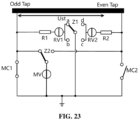
- the transition resistor R of the present application is not set as one, instead, two transition resistors R1 and R2 are set, and the position of the transition resistor R is not set between the fixed end of the action arm of the transfer switch Z 1 and the neutral point of the transformer, but the two transition resistors are respectively set between the loop current vacuum circuit breaker RV1 and the odd tap and between the loop current vacuum circuit breaker RV2 and the even tap.
- This arrangement has the advantage that the two transition resistors R1 and R2 alternately bear the load current and the loop current when the odd tap is switched to the even tap and the even tap is switched to the odd tap, and the two resistors operate alternately and dissipate heat alternately, so that the temperature of the transition resistors can be reduced, the oil decomposition and gas generation of the transformer due to the over-high temperature of the transition resistor are avoided and the insulation performance of the transformer is prevented from being reduced, thus greatly improving the electrical life of the entire changer.
- FIG. 24 shows the one-way rotary design solution and the switching timing state of the transfer switch Z1.
- the movable contact of the transfer switch Z1 is at the fixed contact a and connected to the odd tap, and the initial state of the transfer switch Z1 is state 0.
- the action arm of Z1 is rotated by 90°, the movable contact is changed to be connected to the fixed contact b and connected to the odd tap, and the state is changed from state 0 to state 1.
- the action arm of Z1 When the transfer switch is operated for the second time, the action arm of Z1 is rotated by 90°, the movable contact is changed to be at the fixed contact c and connected to the even tap, and the state is changed from state 1 to state 2.
- the load tap changer is switched from the even tap to the odd tap, the movable contact of Z1 is at the fixed contact c and connected to the even tap, and the initial state of the transfer switch Z1 is state 0.
- the action arm of the transfer switch Z1 When the transfer switch is operated for the first time, the action arm of the transfer switch Z1 is rotated by 90°, and the movable contact is changed to be connected to the fixed contact d and connected to the even tap, and the state is changed from state 0 to state 1.
- the action arm of Z1 When the transfer switch is operated for the second time, the action arm of Z1 is rotated by 90°, the movable contact is changed to be connected to the fixed contact a and connected to the odd tap, and the state is changed from state 1 to state
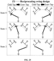
- FIG. 25 shows the reciprocating swing design solution and the switching timing state of the transfer switch Z1.
- the action arm of Z1 When the transfer switch is operated for the second time, the action arm of Z1 is rotated at a large angle, the movable contact is slid over the fixed contact d and connected to the fixed contact c to connect the even tap, and the state is changed from state 1 to state 2.
- the load tap changer When the load tap changer is switched from the even tap to the odd tap, the movable contact of Z1 is at the fixed contact c and connected to the even tap, and the initial state of Z1 is state 0.
- the action arm of Z1 When the transfer switch is operated for the first time, the action arm of Z1 is rotated at a small angle, and the movable contact is changed to be connected to the fixed contact d to connect to the even tap, and the state is changed from state 0 to state 1.
- the present application further provides a control method applied to a symmetrical vacuum bubble load-balancing transition circuit device.
- the transition circuit device includes a transfer switch Z1, a transfer switch Z2, a loop current vacuum circuit breaker RV1, a loop current vacuum circuit breaker RV2, a load current vacuum circuit breaker MV, a main switch MC1, a main switch MC2, and a transition resistor R.
- the method includes the steps described below.
- the action arm of the transfer switch Z1 is connected to one of the electrode a or the electrode b of the transfer switch Z1 to connect to an odd tap of a tap selector of a load tap changer, or the action arm of the transfer switch Z1 is connected to one of the electrode c or the electrode d of the transfer switch Z1 to connect to an even tap of the tap selector of the load tap changer.
- an action arm of the transfer switch Z2 is connected to an electrode e or an electrode f of the transfer switch Z2 to connect to the odd tap or the even tap of the tap selector of the load tap changer, respectively.
- the loop current vacuum circuit breaker RV1 is used for cutting off a loop current between the odd tap and the even tap in a case where the odd tap is switched to the even tap
- the loop current vacuum circuit breaker RV2 is used for cutting off a loop current between the even tap and the odd tap in a case where the even tap is switched to the odd tap.
- the load current vacuum circuit breaker MV is used for cutting off a load current in a case where the odd tap is switched to the even tap or the even tap is switched to the odd tap.
- the main switch MC1 is used for switching a normal through-flow of the odd tap
- the main switch MC2 is used for switching a normal through-flow of the even tap.
- the transition resistor R is used for limiting a loop current between the odd tap and the even tap in a case where the transition circuit simultaneously communicates the odd tap and the even tap.
- the method when the load tap changer is switched from the odd tap to the even tap, the method includes the following:
- the method when the load tap changer is switched from the even tap to the odd tap, the method includes the following:
- the timing of switching from the odd tap to the even tap is mirror symmetrical with the timing of switching from the even tap to the odd tap.
- the "railing" operation of the mechanical transmission mechanism in reciprocating switching processes is avoided, the mechanical complexity is reduced, and the reliability of the changer is improved.
- the task of cutting off the loop current is taken in turn by two loop current vacuum circuit breakers, i.e., the loop current vacuum circuit breaker RV1 and the loop current vacuum circuit breaker RV2, so that the switching task of only one auxiliary vacuum bubble in the topology of the related art is shared, the switching capacity of the vacuum circuit breaker and the switching capacity of the auxiliary vacuum circuit breaker are balanced, and the electrical life of the entire changer is greatly improved.
- the embodiments of the present application may be provided as methods, systems, or computer program products. Therefore, the present application may take the form of a full hardware embodiment, a full software embodiment, or an embodiment combining both software and hardware aspects. Furthermore, the present application may take the form of a computer program product embodied on one or more computer usable storage media (including a magnetic disk storage, a portable compact disc read only memory (CD-ROM), an optical storage and the like), and computer usable program codes are included in the one or more computer usable storage media.
- the solution in the embodiments of the present application may be implemented in a variety of computer languages, such as object-oriented programming language Java and transliterated scripting language JavaScript.
- These computer program instructions may be provided to a general purpose computer, a special purpose computer, an embedded processor, or a processor of other programmable data processing apparatuses so as to produce a machine, so that the instructions, which are executed by the computer or the process of other programmable data processing apparatuses, produce a device for implementing the functions specified in flow or flows in the flowcharts and/or block or blocks in the block diagrams.
- These computer program instructions may also be stored in a computer-readable memory that may direct the computer or other programmable data processing apparatuses to operate in a particular manner, so that the instructions stored in the computer-readable memory produce an article of manufacture including an instruction device, and the instruction device implements the functions specified in flow or flows in the flowcharts and/or block or blocks in the block diagrams.
- These computer program instructions may also be loaded onto a computer or other programmable data processing apparatuses, so that a series of operational steps are performed on the computer or other programmable apparatuses to produce a computer-implemented process, whereby the instructions that are executed on the computer or other programmable apparatuses provide steps for implementing the functions specified in flow or flows in the flowcharts and/or block or blocks in the block diagrams.
Landscapes
- Engineering & Computer Science (AREA)
- Power Engineering (AREA)
- High-Tension Arc-Extinguishing Switches Without Spraying Means (AREA)
Abstract
Description
- The present application claims priority to
Chinese Patent Application No. 202011295536.2, filed with the China National Intellectual Property Administration (CNIPA) on Nov. 18, 2020 - The present application relates to the technical field of tap switches, for example, a symmetrical vacuum bubble load-balancing transition circuit device and a control method.
- A load tap changer is a switching device that provides a constant voltage for a transformer when the load of the transformer changes. The basic principle of the load tap changer is to achieve the switching among taps in a transformer winding while ensuring that the load current is not interrupted, thereby changing the number of windings, i.e., the voltage ratio of the transformer, and finally to achieve the purpose of voltage regulation. A vacuum load tap changer achieves electric arc extinguishing through a vacuum tube of a switch and prevents an electric arc and incandescent gas from being exposed. Oil in the oil chamber of the tap changer is not carbonized and contaminated and does not need to be purified, and burn corrosion of contacts in the vacuum tube may be minimized. The load tap changer is constituted by the switch, a tap selector and an electric mechanism.
- In a case of the load tap changer with the load switching, the load tap changer includes a transition circuit and a selection circuit, different voltage regulation manners require different voltage regulation circuits. Therefore, the circuit of the load tap changer consists of the transition circuit, the selection circuit and a voltage regulation circuit. The transition circuit is a series resistance circuit connected across tap points. The mechanism corresponding to the transition circuit is either the switch or a select switch which is used for transforming the tap of the transformer winding in the charged state. The tap changer implements a tap transfer operation by using the principle of the transition circuit. The transition circuit is divided into a single-resistance transition circuit, a double-resistance transition circuit, a quad-resistance transition circuit or a multi-resistance transition circuit according to the number of transition circuit resistances in the transition circuit, and the transition circuit is divided into a single break circuit, a double break circuit, or the like according to the contact break of the transition circuit, and multiple transition circuits may be formed according to a combination thereof. The transition circuit and the switching procedure have different effects on the contact task of the switch, and whether an electric arc is limited to be reliably extinguished within the first half cycle of the current depends on the desired switching task to a great extent.
- The number of mechanical transfer switches within a switching core of the load tap changer is relatively large, for the pole of the switch, two main circuit switches and two auxiliary transfer switches are included, and the mechanical structure is complicated. A vacuum circuit breaker which is in the load tap changer and not connected to a transition resistor is a load vacuum circuit breaker, and the load vacuum circuit breaker is only responsible for the task of opening and interrupting the load current. A vacuum circuit breaker connected to a transition resistor is a loop current vacuum circuit breaker, and the loop current vacuum circuit breaker is only subjected to the task of opening and interrupting the internal loop current. According to extreme high voltage direct current engineering experience, when the current is transferred and the load is changed, the current on a single pole winding is 500 A to 600 A, the internal loop current flowing through the transition resistor is approximately 900 A to 1000 A, since the internal loop current flowing through the loop current vacuum circuit breaker is significantly greater than the load current, the load vacuum circuit breaker and the loop current vacuum circuit breaker are ablated differently after multiple times of switching, and the switching burden and the electrical damage of the loop current vacuum circuit breaker are more severe.
- The present application provides a symmetrical vacuum bubble load-balancing transition circuit device. The symmetrical vacuum bubble load-balancing transition circuit device includes a transfer switch Z1, a transfer switch Z2, a loop current vacuum circuit breaker RV1. a loop current vacuum circuit breaker RV2, a load current vacuum circuit breaker MV, a main switch MC1, a main switch MC2, and a transition resistor R. The transfer switch Z1 includes an electrode a, an electrode b, an electrode c, an electrode d and an action arm, the electrode a or the electrode b is connected to an odd tap of a tap selector of a load tap changer, the electrode c or the electrode d is connected to an even tap of the tap selector of the load tap changer, and the action arm of the transfer switch Z1 is rotatably connected to one of the electrode a, the electrode b, the electrode c or the electrode d. The transfer switch Z2 includes an electrode e, an electrode f and an action arm, the electrode e and the electrode f are connected to the odd tap of the tap selector of the load tap changer and the even tap of the tap selector of the load tap changer, respectively, and the action arm of the transfer switch Z2 is rotatably connected to one of the electrode e or the electrode f. The loop current vacuum circuit breaker RV1 is configured to cut off a loop current between the odd tap and the even tap in a case where the odd tap is switched to the even tap, and the loop current vacuum circuit breaker RV2 is configured to cut off a loop current between the even tap and the odd tap in a case where the even tap is switched to the odd tap. The load current vacuum circuit breaker MV is configured to cut off a load current in a case where the odd tap is switched to the even tap and the even tap is switched to the odd tap. The main switch MC1 is configured to switch a normal through-flow of the odd tap, and the main switch MC2 is configured to switch a normal through-flow of the even tap. The transition resistor R is configured to limit a loop current between the odd tap and the even tap in a case where a transition circuit simultaneously communicates the odd tap and the even tap.
- The present application further provides a control method applied to a symmetrical vacuum bubble load-balancing transition circuit device. The transition circuit device includes a transfer switch Z1, a transfer switch Z2, a loop current vacuum circuit breaker RV1, a loop current vacuum circuit breaker RV2, a load current vacuum circuit breaker MV, a main switch MC1, a main switch MC2, and a transition resistor R. The method includes the following: An action arm of the transfer switch Z1 is connected to one of an electrode a or an electrode b of the transfer switch Z1 to connect to an odd tap of a tap selector of a load tap changer, or the action arm of the transfer switch Z1 is connected to one of an electrode c or an electrode d of the transfer switch Z1 to connect to an even tap of the tap selector of the load tap changer; an action arm of the transfer switch Z2 is connected to an electrode e or an electrode f of the transfer switch Z2 to connect to the odd tap or the even tap of the tap selector of the load tap changer, respectively; the loop current vacuum circuit breaker RV1 is used for cutting off a loop current between the odd tap and the even tap in a case where the odd tap is switched to the even tap, and the loop current vacuum circuit breaker RV2 is used for cutting off a loop current between the even tap and the odd tap in a case where the even tap is switched to the odd tap; the load current vacuum circuit breaker MV is used for cutting off a load current in a case where the odd tap is switched to the even tap or the even tap is switched to the odd tap; the main switch MC1 is used for switching a normal through-flow of the odd tap, and the main switch MC2 is used for switching a normal through-flow of the even tap; and the transition resistor R is used for limiting a loop current between the odd tap and the even tap in a case where the transition circuit simultaneously communicates the odd tap and the even tap.
-
-
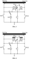
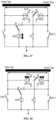
FIG. 1 is a structural diagram of a symmetrical vacuum bubble load-balancing transition circuit device according to an embodiment of the present application; -
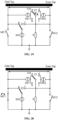
FIG. 2 is a schematic diagram illustrating a transfer of a transition circuit of a load tap changer according to an embodiment of the present application; -
FIG. 3 is a schematic diagram illustrating a transfer of a transition circuit of a load tap changer according to an embodiment of the present application; -
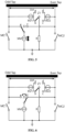
FIG. 4 is a schematic diagram illustrating a transfer of a transition circuit of a load tap changer according to an embodiment of the present application; -
FIG. 5 is a schematic diagram illustrating a transfer of a transition circuit of a load tap changer according to an embodiment of the present application; -
FIG. 6 is a schematic diagram illustrating a transfer of a transition circuit of a load tap changer according to an embodiment of the present application; -
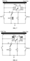
FIG. 7 is a schematic diagram illustrating a transfer of a transition circuit of a load tap changer according to an embodiment of the present application; -
FIG. 8 is a schematic diagram illustrating a transfer of a transition circuit of a load tap changer according to an embodiment of the present application; -
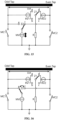
FIG. 9 is a schematic diagram illustrating a transfer of a transition circuit of a load tap changer according to an embodiment of the present application; -
FIG. 10 is a schematic diagram illustrating a transfer of a transition circuit of a load tap changer according to an embodiment of the present application; -
FIG. 11 is a schematic diagram illustrating a transfer of a transition circuit of a load tap changer according to an embodiment of the present application; -
FIG. 12 is a schematic diagram illustrating a transfer of a transition circuit of a load tap changer according to an embodiment of the present application; -
FIG. 13 is a schematic diagram illustrating a transfer of a transition circuit of a load tap changer according to an embodiment of the present application; -
FIG. 14 is a schematic diagram illustrating a transfer of a transition circuit of a load tap changer according to an embodiment of the present application; -
FIG. 15 is a schematic diagram illustrating a transfer of a transition circuit of a load tap changer according to an embodiment of the present application; -
FIG. 16 is a schematic diagram illustrating a transfer of a transition circuit of a load tap changer according to an embodiment of the present application; -
FIG. 17 is a schematic diagram illustrating a transfer of a transition circuit of a load tap changer according to an embodiment of the present application; -
FIG. 18 is a schematic diagram illustrating a transfer of a transition circuit of a load tap changer according to an embodiment of the present application; -
FIG. 19 is a schematic diagram illustrating a transfer of a transition circuit of a load tap changer according to an embodiment of the present application; -
FIG. 20 is a schematic diagram illustrating a transfer of a transition circuit of a load tap changer according to an embodiment of the present application; -
FIG. 21 is a schematic diagram illustrating a transfer procedure from N to N+1 of a transition circuit of a load tap changer according to an embodiment of the present application; -
FIG. 22 is a schematic diagram illustrating a transfer procedure from N+1 to N of a transition circuit of a load tap changer according to an embodiment of the present application; -
FIG. 23 is a structural diagram of a transition circuit, including two transition resistors, of a load tap changer according to an embodiment of the present application; -
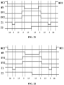
FIG. 24 is a switching timing state diagram of a transfer switch Z1 according to an embodiment of the present application; -
FIG. 25 is a switching timing state diagram of a transfer switch Z1 according to an embodiment of the present application; and -
FIG. 26 is a flowchart of a control method applied to a symmetrical vacuum bubble load-balancing transition circuit device according to an embodiment of the present application. - Exemplary embodiments of the present application are described with reference to the drawings, however, the present application may be embodied in many different forms and is not limited to the embodiments described herein, and these embodiments are provided to describe the present application. Terms in the exemplary embodiments shown in the drawings are not intended to be limiting of the present application. In the drawings, the same reference numerals are used for the same units/elements.
- Terms (including scientific and technical terms) used herein have commonly understood meanings. Terms defined in commonly used dictionaries should be understood to have a meaning consistent with the context of their relevant art.
- The present application provides a symmetrical vacuum bubble load-balancing transition circuit device. As shown in
FIG. 1 , the symmetrical vacuum bubble load-balancing transition circuit device includes a transfer switch Z1, a transfer switch Z2, a loop current vacuum circuit breaker RV1, a loop current vacuum circuit breaker RV2, a load current vacuum circuit breaker MV, a main switch MC1, a main switch MC2, and a transition resistor R. The transfer switch Z1 includes an electrode a, an electrode b, an electrode c, an electrode d and an action arm, the electrode a or the electrode b is connected to an odd tap of a tap selector of a load tap changer, the electrode c or the electrode d is connected to an even tap of the tap selector of the load tap changer, and the action arm of the transfer switch Z1 is rotatably connected to one of the electrode a, the electrode b, the electrode c or the electrode d. The transfer switch Z2 includes an electrode e, an electrode f and an action arm, the electrode e and the electrode f are connected to the odd tap of the tap selector of the load tap changer and the even tap of the tap selector of the load tap changer, respectively, and the action arm of the transfer switch Z2 is rotatably connected to one of the electrode e or the electrode f. The loop current vacuum circuit breaker RV1 is configured to cut off a loop current between the odd tap and the even tap when the odd tap is switched to the even tap, and the loop current vacuum circuit breaker RV2 is configured to cut off a loop current between the even tap and the odd tap when the even tap is switched to the odd tap. The load current vacuum circuit breaker MV is configured to cut off a load current when the odd tap is switched to the even tap or the even tap is switched to the odd tap. The main switch MC1 is configured to switch a normal through-flow of the odd tap, the main switch MC2 is configured to switch a normal through-flow of the even tap, the components such as Z1, Z2, MV, RV1, and RV2 are in a static state when the switching core of a tap switch does not operate, at this time, the current flows through the switching core of the tap switch by means of the main switch MC1 or the main switch MC2, and the current flowing at this time is the normal through-flow. - The transition resistor R is configured to limit a loop current between the odd tap and the even tap when the transition circuit simultaneously communicates the odd tap and the even tap.
- For the loop current vacuum circuit breaker RV1 and the loop current vacuum circuit breaker RV2, the loop current vacuum
circuit breaker RV 1 is connected to one of the electrode a or the electrode b of the transfer switch Z1, and the loop current vacuum circuit breaker RV2 is connected to one of the electrode c or the electrode d of the transfer switch Z1. - The fixed end of the action arm of the transfer switch Z1 is connected to one end of the transition resistor R and is connected to the neutral point of a transformer through the transition resistor R.
- The fixed end of the action arm of the transfer switch Z2 is connected to one end of the load current vacuum circuit breaker MV and is connected to the neutral point of the transformer through the load current vacuum circuit breaker MV
- The main switch MC1 is connected between the odd tap of the tap selector of the load tap changer and the neutral point of the transformer, and the main switch MC2 is connected between the even tap of the tap selector of the load tap changer and the neutral point of the transformer.
- When the tap of the tap selector of the load tap changer is the odd tap, the main switch MC1 is switched on and the main switch MC2 is switched off;
- the action arm of the transfer switch Z1 is in conduction with the electrode a, and the action arm of the transfer switch Z2 is in conduction with the electrode e; and
- the load current vacuum circuit breaker MV is switched on, the loop current vacuum circuit breaker RV1 and the loop current vacuum circuit breaker RV2 are switched off, and the load current is output in a manner of being connected to the neutral point of the transformer through the main switch MC1 while being connected to the electrode e of the transfer switch Z2 and the load current vacuum circuit breaker MV which are in parallel connection with the main switch MC1.
- When the tap of the tap selector of the load tap changer is the odd tap, the main switch MC1 is switched on and the main switch MC2 is switched off; the action arm of the transfer switch Z1 is in conduction with the electrode a, and the action arm of the transfer switch Z2 is in conduction with the electrode e; and the load current vacuum circuit breaker MV is switched on, the loop current vacuum circuit breaker RV1 and the loop current vacuum circuit breaker RV2 are switched off, and the load current is output from the neutral point of the transformer after passing through a circuit formed by the main switch MC1 in parallel connection with the electrode e of the transfer switch Z2 and the load current vacuum circuit breaker MV
- When the tap of the load tap changer is the even tap, the main switch MC2 is switched on and the main switch MC1 is switched off;
- the action arm of the transfer switch Z1 is in conduction with the electrode c, and the action arm of the transfer switch Z2 is in conduction with the electrode f; and
- the load current vacuum circuit breaker MV is switched on, the loop current vacuum circuit breaker RV1 and the loop current vacuum circuit breaker RV2 are switched off, and the load current is output in a manner of being connected to the neutral point of the transformer via the main switch MC2 while being connected to the electrode f of the action arm of the transfer switch Z2 and the load current vacuum circuit breaker MV which are in parallel connection with the main switch MC2.
- When the tap of the tap selector of the load tap changer is the even tap, the main switch MC2 is switched on and the main switch MC1 is switched off;
- the action arm of the transfer switch Z1 is in conduction with the electrode c, and the action arm of the transfer switch Z2 is in conduction with the electrode f; and
- the load current vacuum circuit breaker MV is switched on, the loop current vacuum circuit breaker RV1 and the loop current vacuum circuit breaker RV2 are switched off, and the load current is output from the neutral point of the transformer after passing through a circuit formed by the main switch MC2 in parallel connection with the electrode f of the action arm of the transfer switch Z2, and the load current vacuum circuit breaker MV
- The present application is described below in connection with the embodiments.
- A transition circuit device of a vacuum-type load tap changer in this embodiment includes a transfer switch Z1, a transfer switch Z2, a loop current vacuum circuit breaker RV1, a loop current vacuum circuit breaker RV2, a load current vacuum circuit breaker MV, and a transition resistor R. Multiple transition resistors R may be provided, and a main switch MC1 and a main switch MC2 are respectively provided in an odd tap main circuit and an even tap main circuit of the changer.
- The transfer switch Z1 includes an electrode a, an electrode b, an electrode c and an electrode d, the electrode a or the electrode b is connected to an odd tap of a tap selector of the load tap changer, the electrode c or the electrode d is connected to an even tap of the tap selector of the load tap changer, and a fixed end of an action arm of the transfer switch Z1 is connected to the transition resistor R.
- The transfer switch Z2 includes an electrode e and an electrode f, the electrode e and the electrode f are connected to the odd tap and the even tap of the tap selector of the load tap changer, respectively, and a fixed end of an action arm of the transfer switch Z2 is connected to a neutral point of a transformer through the load current vacuum circuit breaker MV
- The loop current vacuum circuit breaker RV1 is configured to cut off a loop current between the odd tap and the even tap when the odd tap is switched to the even tap, and the loop current vacuum circuit breaker RV2 is configured to cut off a loop current between the even tap and the odd tap when the even tap is switched to the odd tap.
- The load current vacuum circuit breaker MV is configured to cut off a load current when the odd tap is switched to the even tap or the even tap is switched to the odd tap.
- The main switch MC1 and the main switch MC2 are configured to switch a normal through-flow before and after the completion.
- The operation process of the transition circuit is as follows.
- Assuming that the initial point position of the tap selector of the load tap changer is unchanged, the tap number of the load tap changer is consistent with the contact group number of the tap selector, and the tap of the load tap changer is raised from an odd tap to an even tap.
- When the tap of the load tap changer is the odd tap, as shown in
FIG. 1 , the main switch MC1 is switched on, the main switch MC2 is switched off, a movable contact of the action arm of the transfer switch Z1 is in conduction with the electrode a, a movable contact of the action arm of the transfer switch Z2 is in conduction with the electrode e, the load current vacuum circuit breaker MV is switched on, the loop current vacuum circuit breaker RV1 and the loop current vacuum circuit breaker RV2 are switched off, the load current IN is output in a manner of being connected to the neutral point of the transformer through the main switch MC1 while being connected to the electrode e of the transfer switch Z2 and the load current vacuum circuit breaker MV which are in parallel connection with the main switch MC1. - When the load tap changer is switched from the odd tap to the even tap, the operation steps of the transition circuit are as follows.
- As shown in
FIG. 2 , the main switch MC1 is switched off, and the load current IN of the odd tap is output in a manner of flowing through the transfer switch Z2 and the load current vacuum circuit breaker MV - As shown in
FIG. 3 , the movable contact of the action arm of the transfer switch Z1 is switched from the fixed contact a to the fixed contact b. At this time, the transfer switch Z1 is not charged, and Z1 is still connected to the odd tap of the load tap changer. - As shown in
FIG. 4 , the loop current vacuum circuit breaker RV1 and the loop current vacuum circuit breaker RV2 are simultaneously switched on, and the load current IN of the odd tap is output after flowing through the transfer switch Z2 and the load current vacuum circuit breaker MV, meanwhile, the transfer switch Z2 and the load current vacuum circuit breaker MV are connected in parallel with the transition resistor R and the loop current vacuum circuit breaker RV1 to output the load current IN via the contact b of the transfer switch Z1. - As shown in
FIG. 5 , the load current vacuum circuit breaker MV is switched off, the load current IN is cut off, and an electric arc is generated. After the electric arc is extinguished, the load current IN of the odd tap is output after sequentially flowing through the transition resistor R, the loop current vacuum circuit breaker RV1, and the contact b of the transfer switch Z1, and a recovery voltage UMV between the two ends of the load current vacuum circuit breaker MV is equal to IN×R. - As shown in
FIG. 6 , after the electric arc in the load current vacuum circuit breaker MV is completely extinguished, the action arm of the transfer switch Z2 is switched from the fixed contact e to the fixed contact f, and the load current IN of the odd tap is output after sequentially flowing through the transition resistor R, the loop current vacuum circuit breaker RV1, and the contact b of the transfer switch Z1. - As shown in
FIG. 7 , the load current vacuum circuit breaker MV is switched on, and the transition circuit is simultaneously connected to the odd tap and the even tap to form a bridging connection and generate a circulating current IC , where
- As shown in
FIG. 8 , the loop current vacuum circuit breaker RV1 and the loop current vacuum circuit breaker RV2 are simultaneously switched off. The loop current vacuum circuit breaker RV1 brings on the loop current IC , and an electric arc is generated. The loop current vacuum circuit breaker RV2 is operated without current. The load current IN of the even tap is output after flowing through the contact f of the transfer switch Z2 and the load current vacuum circuit breaker MV, and a recovery voltage URV1 between the two ends of the loop current vacuum circuit breaker RV1 is equal to Ust. - As shown in
FIG. 9 , after the electric arc in the loop current vacuum circuit breaker RV1 is completely extinguished, the movable contact of the action arm of the transfer switch Z1 is switched from the fixed contact b to the fixed contact c, and the load current IN of the even tap is output after flowing through the f contact of the transfer switch Z2 and the load current vacuum circuit breaker MV - As shown in
FIG. 10 , the main switch MC2 is switched on, and the load current IN of the even tap is output in a manner of flowing through the main switch MC2 while being connected to the contact f of the transfer switch Z2 and the load current vacuum circuit breaker MV which are in parallel connection with the main switch MC2. At this time, the tap transformation operation ends, and the voltage regulation of switching from the odd tap to the even tap is completed by the switching core. - When the tap of the load tap changer is an even tap, as shown in
FIG. 11 , the main switch MC2 is switched on and the main switch MC1 is switched off, the movable contact of the action arm of the transfer switch Z1 is in conduction with the fixed contact c, the movable contact of the action arm of the transfer switch Z2 is in conduction with the fixed contact f, the load current vacuum circuit breaker MV is switched on, the loop current vacuum circuit breaker RV1 and the loop current vacuum circuit breaker RV2 are switched off, the load current IN is output in a manner of being connected to the neutral point of the transformer through the main switch MC2 while being connected to the contact f of the transfer switch Z2 and the load current vacuum circuit breaker MV which are in parallel connection with the main switch MC2. - When the load tap changer is switched from the even tap to the odd tap, the operation steps of the transition circuit are as follows.
- As shown in
FIG. 12 , the main switch MC2 is switched off, and the load current IN of the even tap is output after flowing through the transfer switch Z2 and the load current vacuum circuit breaker MV - As shown in
FIG. 13 , the movable contact of the action arm of the transfer switch Z1 is switched from the fixed contact c to the fixed contact d. At this time, the transfer switch Z1 is not charged, and the transfer switch Z1 is still connected to the even tap of the load tap changer. - As shown in
FIG. 14 , the loop current vacuum circuit breaker RV1 and the loop current vacuum circuit breaker RV2 are simultaneously switched on, and the load current IN of the even tap is output after flowing through the transfer switch Z2 and the load current vacuum circuit breaker MV, meanwhile, the transfer switch Z2 and the load current vacuum circuit breaker MV are connected in parallel with the transition resistor R and the loop current vacuum circuit breaker RV2 to output the load current IN via the contact d of the transfer switch Z1. - As shown in
FIG. 15 , the load current vacuum circuit breaker MV is switched off, the load current IN is cut off, and an electric arc is generated. After the electric arc is extinguished, the load current IN of the even tap is output after sequentially flowing through the transition resistor R, the loop current vacuum circuit breaker RV2, and the contact d of the transfer switch Z1, and a recovery voltage UMV between the two ends of the load current vacuum circuit breaker MV is equal to IN×R. - As shown in
FIG. 16 , after the electric arc in the load current vacuum circuit breaker MV is completely extinguished, the action arm of the transfer switch Z2 is switched from the fixed contact f to the fixed contact e, and the load current IN of the even tap is output after sequentially flowing through the transition resistor R, the loop current vacuum circuit breaker RV2, and the contact d of the transfer switch Z1. - As shown in
FIG. 17 , the load current vacuum circuit breaker MV is switched on, and the transition circuit is simultaneously connected to the even tap and the odd tap to form a bridging connection and generate a circulating current IC , where
- As shown in
FIG. 18 , the loop current vacuum circuit breaker RV1 and the loop current vacuum circuit breaker RV2 are simultaneously switched off. The loop current vacuum circuit breaker RV2 brings on the loop current IC , and an electric arc is generated. The loop current vacuum circuit breaker RV1 is operated without current. The load current IN of the odd tap is output after flowing through the contact e of the transfer switch Z2 and the load current vacuum circuit breaker MV, and the recovery voltage URV2 between the two ends of the loop current vacuum circuit breaker RV2 is equal to Ust. - As shown in
FIG. 19 , after the electric arc in the loop current vacuum circuit breaker RV2 is completely extinguished, the movable contact of the action arm of the transfer switch Z1 is switched from the fixed contact d to the fixed contact a, and the load current IN of the odd tap is output after flowing through the contact e of the transfer switch Z2 and the load current vacuum circuit breaker MV - As shown in
FIG. 20 , the main switch MC1 is switched on, and the load current IN of the odd tap is output in a manner of flowing through the main switch MC1 while being connected to the contact e of the transfer switch Z2 and the load current vacuum circuit breaker MV which are in parallel connection with the main switch MC1. At this time, the tap transformation operation ends, and the voltage regulation of switching from the even tap to the odd tap is completed by the switching core. - When the tap selector is transferred from the odd tap to the even tap, a schematic diagram of the transfer procedure of the transition circuit is shown in
FIG. 21 . - When the tap selector is transferred from the even tap to the odd tap, a schematic diagram of the transfer procedure of the transition circuit is shown in
FIG. 22 . - The task of the vacuum circuit breaker in the transition circuit of the vacuum-type load tap changer in this embodiment is shown in Table 1.
Table 1 Operation direction Load current vacuum circuit breaker Loop current vacuum circuit breaker Circuit breaker On/off current Recovery voltage Number of operations Circuit breaker On/off current Recovery voltage Number of operations Odd→ Even MV IN IN*R N/2 RV1 
USt N/2 RV2 0 0 0 Even→ Odd MV IN IN*R N/2 RV1 0 0 0 RV2 
USt N/2 N is the number of tap switching times of the load tap changer, IN is the load current, Ust is the stage voltage of the load tap changer, and R is the transition resistor. -
FIG. 23 shows a modified embodiment of a load transfer switch of the load tap changer provided in the present application. Here, the transition resistor R of the present application is not set as one, instead, two transition resistors R1 and R2 are set, and the position of the transition resistor R is not set between the fixed end of the action arm of thetransfer switch Z 1 and the neutral point of the transformer, but the two transition resistors are respectively set between the loop current vacuum circuit breaker RV1 and the odd tap and between the loop current vacuum circuit breaker RV2 and the even tap. This arrangement has the advantage that the two transition resistors R1 and R2 alternately bear the load current and the loop current when the odd tap is switched to the even tap and the even tap is switched to the odd tap, and the two resistors operate alternately and dissipate heat alternately, so that the temperature of the transition resistors can be reduced, the oil decomposition and gas generation of the transformer due to the over-high temperature of the transition resistor are avoided and the insulation performance of the transformer is prevented from being reduced, thus greatly improving the electrical life of the entire changer. -
FIG. 24 shows the one-way rotary design solution and the switching timing state of the transfer switch Z1. When the load tap changer is switched from the odd tap to the even tap, the movable contact of the transfer switch Z1 is at the fixed contact a and connected to the odd tap, and the initial state of the transfer switch Z1 isstate 0. When the transfer switch is operated for the first time, the action arm of Z1 is rotated by 90°, the movable contact is changed to be connected to the fixed contact b and connected to the odd tap, and the state is changed fromstate 0 tostate 1. When the transfer switch is operated for the second time, the action arm of Z1 is rotated by 90°, the movable contact is changed to be at the fixed contact c and connected to the even tap, and the state is changed fromstate 1 tostate 2. When the load tap changer is switched from the even tap to the odd tap, the movable contact of Z1 is at the fixed contact c and connected to the even tap, and the initial state of the transfer switch Z1 isstate 0. When the transfer switch is operated for the first time, the action arm of the transfer switch Z1 is rotated by 90°, and the movable contact is changed to be connected to the fixed contact d and connected to the even tap, and the state is changed fromstate 0 tostate 1. When the transfer switch is operated for the second time, the action arm of Z1 is rotated by 90°, the movable contact is changed to be connected to the fixed contact a and connected to the odd tap, and the state is changed fromstate 1 tostate 2. -
FIG. 25 shows the reciprocating swing design solution and the switching timing state of the transfer switch Z1. When the load tap changer is switched from the odd tap to the even tap, the movable contact of Z1 is at the fixed contact a and connected to the odd tap, and the initial state of the switch Z1 isstate 0. When the transfer switch is operated for the first time, the action arm of Z1 is rotated at a small angle, the movable contact is changed to be connected to the fixed contact b to connect to the odd tap, and the state is changed fromstate 0 tostate 1. When the transfer switch is operated for the second time, the action arm of Z1 is rotated at a large angle, the movable contact is slid over the fixed contact d and connected to the fixed contact c to connect the even tap, and the state is changed fromstate 1 tostate 2. When the load tap changer is switched from the even tap to the odd tap, the movable contact of Z1 is at the fixed contact c and connected to the even tap, and the initial state of Z1 isstate 0. When the transfer switch is operated for the first time, the action arm of Z1 is rotated at a small angle, and the movable contact is changed to be connected to the fixed contact d to connect to the even tap, and the state is changed fromstate 0 tostate 1. When the transfer switch is operated for the second time, the action arm of Z1 is rotated at a large angle, the movable contact is slid over the fixed contact b and connected to the fixed contact a to connect to the odd tap, and the state is changed fromstate 1 tostate 2. - The present application further provides a control method applied to a symmetrical vacuum bubble load-balancing transition circuit device. The transition circuit device includes a transfer switch Z1, a transfer switch Z2, a loop current vacuum circuit breaker RV1, a loop current vacuum circuit breaker RV2, a load current vacuum circuit breaker MV, a main switch MC1, a main switch MC2, and a transition resistor R. As shown in
FIG. 26 , the method includes the steps described below. - In S10, the action arm of the transfer switch Z1 is connected to one of the electrode a or the electrode b of the transfer switch Z1 to connect to an odd tap of a tap selector of a load tap changer, or the action arm of the transfer switch Z1 is connected to one of the electrode c or the electrode d of the transfer switch Z1 to connect to an even tap of the tap selector of the load tap changer.
- In S20, an action arm of the transfer switch Z2 is connected to an electrode e or an electrode f of the transfer switch Z2 to connect to the odd tap or the even tap of the tap selector of the load tap changer, respectively.
- In S30, the loop current vacuum circuit breaker RV1 is used for cutting off a loop current between the odd tap and the even tap in a case where the odd tap is switched to the even tap, and the loop current vacuum circuit breaker RV2 is used for cutting off a loop current between the even tap and the odd tap in a case where the even tap is switched to the odd tap.
- In S40, the load current vacuum circuit breaker MV is used for cutting off a load current in a case where the odd tap is switched to the even tap or the even tap is switched to the odd tap.
- In S50, the main switch MC1 is used for switching a normal through-flow of the odd tap, and the main switch MC2 is used for switching a normal through-flow of the even tap.
- In S60, the transition resistor R is used for limiting a loop current between the odd tap and the even tap in a case where the transition circuit simultaneously communicates the odd tap and the even tap.
- Optionally, when the load tap changer is switched from the odd tap to the even tap, the method includes the following:
- The main switch MC1 is switched off;
- the action arm of the transfer switch Z1 is switched from connecting to the electrode a to connecting to the electrode b;
- the loop current vacuum circuit breaker RV1 and the loop current vacuum circuit breaker RV2 are switched on;
- the load current vacuum circuit breaker MV is switched off;
- the action arm of the transfer switch Z2 is switched from connecting to the electrode e to connecting to the electrode f after an electric arc in the load current vacuum circuit breaker MV is completely extinguished;
- the load current vacuum circuit breaker MV is switched on, and the transition circuit is simultaneously connected to the odd tap and the even tap to form a bridging connection and generate a circulating current;
- the loop current vacuum circuit breaker RV1 and the loop current vacuum circuit breaker RV2 are switched off;
- the action arm of the transfer switch Z1 is switched from connecting to the electrode b to connecting to the electrode c after an electric arc in the loop current vacuum circuit breaker RV1 is completely extinguished; and
- the main switch MC2 is switched on.
- Optionally, when the load tap changer is switched from the even tap to the odd tap, the method includes the following:
- The main switch MC2 is switched off;
- the action arm of the transfer switch Z1 is switched from the electrode c to the electrode d;
- the loop current vacuum circuit breaker RV1 and the loop current vacuum circuit breaker RV2 are switched on;
- the load current vacuum circuit breaker MV is switched off;
- the action arm of the transfer switch Z2 is switched from the electrode f to the electrode e after an electric arc in the load current vacuum circuit breaker MV is completely extinguished;
- the load current vacuum circuit breaker MV is switched on, and the transition circuit is simultaneously connected to the even tap and the odd tap to form a bridging connection and generate a circulating current;
- the loop current vacuum circuit breaker RV1 and the loop current vacuum circuit breaker RV2 are switched off;
- the action arm of the transfer switch Z1 is switched from the electrode d to the electrode a after an electric arc in the loop current vacuum circuit breaker RV2 is completely extinguished; and
- the main switch MC1 is switched on.
- In a transition process of the present application, the timing of switching from the odd tap to the even tap is mirror symmetrical with the timing of switching from the even tap to the odd tap. For a switch performing a reciprocating operation, the "railing" operation of the mechanical transmission mechanism in reciprocating switching processes is avoided, the mechanical complexity is reduced, and the reliability of the changer is improved.
- The task of cutting off the loop current is taken in turn by two loop current vacuum circuit breakers, i.e., the loop current vacuum circuit breaker RV1 and the loop current vacuum circuit breaker RV2, so that the switching task of only one auxiliary vacuum bubble in the topology of the related art is shared, the switching capacity of the vacuum circuit breaker and the switching capacity of the auxiliary vacuum circuit breaker are balanced, and the electrical life of the entire changer is greatly improved.
- The embodiments of the present application may be provided as methods, systems, or computer program products. Therefore, the present application may take the form of a full hardware embodiment, a full software embodiment, or an embodiment combining both software and hardware aspects. Furthermore, the present application may take the form of a computer program product embodied on one or more computer usable storage media (including a magnetic disk storage, a portable compact disc read only memory (CD-ROM), an optical storage and the like), and computer usable program codes are included in the one or more computer usable storage media. The solution in the embodiments of the present application may be implemented in a variety of computer languages, such as object-oriented programming language Java and transliterated scripting language JavaScript.
- The present application is described with reference to flowcharts and/or block diagrams of methods, apparatuses (systems), and computer program products according to the embodiments of the present application. It should be understood that each flow and/or block in the flowcharts and/or block diagrams, and combinations of flow and/or block in the flowcharts and/or block diagrams may be implemented by computer program instructions. These computer program instructions may be provided to a general purpose computer, a special purpose computer, an embedded processor, or a processor of other programmable data processing apparatuses so as to produce a machine, so that the instructions, which are executed by the computer or the process of other programmable data processing apparatuses, produce a device for implementing the functions specified in flow or flows in the flowcharts and/or block or blocks in the block diagrams.
- These computer program instructions may also be stored in a computer-readable memory that may direct the computer or other programmable data processing apparatuses to operate in a particular manner, so that the instructions stored in the computer-readable memory produce an article of manufacture including an instruction device, and the instruction device implements the functions specified in flow or flows in the flowcharts and/or block or blocks in the block diagrams.
- These computer program instructions may also be loaded onto a computer or other programmable data processing apparatuses, so that a series of operational steps are performed on the computer or other programmable apparatuses to produce a computer-implemented process, whereby the instructions that are executed on the computer or other programmable apparatuses provide steps for implementing the functions specified in flow or flows in the flowcharts and/or block or blocks in the block diagrams.
Claims (10)
- A symmetrical vacuum bubble load-balancing transition circuit device, comprising:a transfer switch Z1, wherein the transfer switch Z1 comprises an electrode a, an electrode b, an electrode c, an electrode d and an action arm, wherein the electrode a or the electrode b is connected to an odd tap of a tap selector of a load tap changer, the electrode c or the electrode d is connected to an even tap of the tap selector of the load tap changer, and the action arm of the transfer switch Z1 is rotatably connected to one of the electrode a, the electrode b, the electrode c, or the electrode d;a transfer switch Z2, wherein the transfer switch Z2 comprises an electrode e, an electrode f and an action arm, wherein the electrode e and the electrode f are connected to the odd tap of the tap selector of the load tap changer and the even tap of the tap selector of the load tap changer, respectively, and the action arm of the transfer switch Z2 is rotatably connected to one of the electrode e or the electrode f;a loop current vacuum circuit breaker RV1 and a loop current vacuum circuit breaker RV2, wherein the loop current vacuum circuit breaker RV1 is configured to cut off a loop current between the odd tap and the even tap in a case where the odd tap is switched to the even tap, and the loop current vacuum circuit breaker RV2 is configured to cut off a loop current between the even tap and the odd tap in a case where the even tap is switched to the odd tap;a load current vacuum circuit breaker MV configured to cut off a load current in a case where the odd tap is switched to the even tap or the even tap is switched to the odd tap;a main switch MC1 and a main switch MC2, wherein the main switch MC1 is configured to switch a normal through-flow of the odd tap, and the main switch MC2 is configured to switch a normal through-flow of the even tap; anda transition resistor R configured to limit a loop current between the odd tap and the even tap in a case where a transition circuit simultaneously communicates the odd tap and the even tap.
- The device of claim 1, wherein the loop current vacuum circuit breaker RV1 is connected to one of the electrode a or the electrode b of the transfer switch Z1, and the loop current vacuum circuit breaker RV2 is connected to one of the electrode c or the electrode d of the transfer switch Z1.
- The device of claim 1, wherein a fixed end of the action arm of the transfer switch Z1 is connected to one end of the transition resistor R and is connected to a neutral point of a transformer through the transition resistor R.
- The device of claim 1, wherein a fixed end of the action arm of the transfer switch Z2 is connected to one end of the load current vacuum circuit breaker MV and is connected to a neutral point of a transformer through the load current vacuum circuit breaker MV
- The device of claim 1, wherein the main switch MC1 is connected between the odd tap of the tap selector of the load tap changer and a neutral point of a transformer, and the main switch MC2 is connected between the even tap of the tap selector of the load tap changer and the neutral point of the transformer.
- The device of claim 1, wherein in a case where a tap of the load tap changer is the odd tap, the main switch MC1 is switched on and the main switch MC2 is switched off;the action arm of the transfer switch Z1 is in conduction with the electrode a, and the action arm of the transfer switch Z2 is in conduction with the electrode e; andthe load current vacuum circuit breaker MV is switched on, the loop current vacuum circuit breaker RV1 and the loop current vacuum circuit breaker RV2 are switched off, and the load current is output from a neutral point of a transformer after passing through a circuit formed by the main switch MC1 in parallel connection with the electrode e of the transfer switch Z2 and the load current vacuum circuit breaker MV
- The device of claim 1, wherein in a case where a tap of the tap selector of the load tap changer is the even tap, the main switch MC2 is switched on and the main switch MC1 is switched off;the action arm of the transfer switch Z1 is in conduction with the electrode c, and the action arm of the transfer switch Z2 is in conduction with the electrode f; andthe load current vacuum circuit breaker MV is switched on, the loop current vacuum circuit breaker RV1 and the loop current vacuum circuit breaker RV2 are switched off, and the load current is output from a neutral point of a transformer after passing through a circuit formed by the main switch MC2 in parallel connection with the electrode f of the action arm of the transfer switch Z2, and the load current vacuum circuit breaker MV
- A control method applied to a symmetrical vacuum bubble load-balancing transition circuit device, wherein the transition circuit device comprises a transfer switch Z1, a transfer switch Z2, a loop current vacuum circuit breaker RV1, a loop current vacuum circuit breaker RV2, a load current vacuum circuit breaker MV, a main switch MC1, a main switch MC2, and a transition resistor R, and the method comprises:connecting an action arm of the transfer switch Z1 to one of an electrode a of the transfer switch Z 1 or an electrode b of the transfer switch Z 1 to connect to an odd tap of a tap selector of a load tap changer, or connecting an action arm of the transfer switch Z 1 to one of an electrode c of the transfer switch Z1 or an electrode d of the transfer switch Z1 to connect to an even tap of the tap selector of the load tap changer;connecting an action arm of the transfer switch Z2 to an electrode e of the transfer switch Z or an electrode f of the transfer switch Z2 to connect to the odd tap or the even tap of the tap selector of the load tap changer, respectively;using the loop current vacuum circuit breaker RV1 to cut off a loop current between the odd tap and the even tap in a case where the odd tap is switched to the even tap, and using the loop current vacuum circuit breaker RV2 to cut off a loop current between the even tap and the odd tap in a case where the even tap is switched to the odd tap;using the load current vacuum circuit breaker MV to cut off a load current in a case where the odd tap is switched to the even tap and the even tap is switched to the odd tap;using the main switch MC1 to switch a normal through-flow of the odd tap, and using the main switch MC2 to switch a normal through-flow of the even tap; andusing the transition resistor R to limit a loop current between the odd tap and the even tap in a case where a transition circuit simultaneously communicates the odd tap and the even tap.
- The method of claim 8, wherein in a case where the load tap changer is switched from the odd tap to the even tap, the method comprises:switching off the main switch MC1;switching the action arm of the transfer switch Z1 from connecting to the electrode a to connecting to the electrode b;switching on the loop current vacuum circuit breaker RV1 and the loop current vacuum circuit breaker RV2;switching off the load current vacuum circuit breaker MV;switching the action arm of the transfer switch Z2 from connecting to the electrode e to connecting to the electrode f after an electric arc in the load current vacuum circuit breaker MV is completely extinguished;switching on the load current vacuum circuit breaker MV, and connecting the transition circuit simultaneously to the odd tap and the even tap to form a bridging connection and generate a circulating current;switching off the loop current vacuum circuit breaker RV1 and the loop current vacuum circuit breaker RV2;switching the action arm of the transfer switch Z1 from connecting to the electrode b to connecting to the electrode c after an electric arc in the loop current vacuum circuit breaker RV1 is completely extinguished; andswitching on the main switch MC2.
- The method of claim 8, wherein in a case where the load tap changer is switched from the even tap to the odd tap, the method comprises:switching off the main switch MC2;switching the action arm of the transfer switch Z1 from connecting to the electrode c to connecting to the electrode d;switching on the loop current vacuum circuit breaker RV1 and the loop current vacuum circuit breaker RV2;switching off the load current vacuum circuit breaker MV;switching the action arm of the transfer switch Z2 from connecting to the electrode f to connecting to the electrode e after an electric arc in the load current vacuum circuit breaker MV is completely extinguished;switching on the load current vacuum circuit breaker MV, and connecting the transition circuit simultaneously to the even tap and the odd tap to form a bridging connection and generate a circulating current;switching off the loop current vacuum circuit breaker RV1 and the loop current vacuum circuit breaker RV2;switching the action arm of the transfer switch Z1 from connecting to the electrode d to connecting to the electrode a after an electric arc in the loop current vacuum circuit breaker RV2 is completely extinguished; andswitching on the main switch MC1.
Applications Claiming Priority (2)
| Application Number | Priority Date | Filing Date | Title |
|---|---|---|---|
| CN202011295536.2A CN112670067B (en) | 2020-11-18 | 2020-11-18 | Symmetrical vacuum bubble load balancing transition circuit device and control method |
| PCT/CN2020/132693 WO2022104902A1 (en) | 2020-11-18 | 2020-11-30 | Symmetrical vacuum bubble load-balancing transition circuit apparatus, and control method |
Publications (2)
| Publication Number | Publication Date |
|---|---|
| EP4250320A1 true EP4250320A1 (en) | 2023-09-27 |
| EP4250320A4 EP4250320A4 (en) | 2024-10-16 |
Family
ID=75402976
Family Applications (1)
| Application Number | Title | Priority Date | Filing Date |
|---|---|---|---|
| EP20962193.7A Pending EP4250320A4 (en) | 2020-11-18 | 2020-11-30 | SYMMETRICAL VACUUM BUBBLE LOAD COMPENSATION TRANSITION CIRCUIT AND CONTROL METHODS |
Country Status (3)
| Country | Link |
|---|---|
| EP (1) | EP4250320A4 (en) |
| CN (1) | CN112670067B (en) |
| WO (1) | WO2022104902A1 (en) |
Families Citing this family (5)
| Publication number | Priority date | Publication date | Assignee | Title |
|---|---|---|---|---|
| CN114883121B (en) * | 2021-08-09 | 2024-10-01 | 中国电力科学研究院有限公司 | Symmetrical double vacuum bubble transition circuit for vacuum on-load tap changer |
| CN113889329B (en) * | 2021-09-26 | 2023-12-15 | 上海华明电力设备制造有限公司 | On-load tap changer switching method, circuit and device |
| CN113851314B (en) * | 2021-09-28 | 2025-02-28 | 西安交通大学 | A single-resistance symmetrical transition circuit and voltage regulation method for an on-load tap changer |
| CN114093594A (en) * | 2021-12-01 | 2022-02-25 | 中国电力科学研究院有限公司 | Transition circuit of on-load tap-changer and control method |
| CN115938766A (en) * | 2022-12-15 | 2023-04-07 | 西安交通大学 | A three-vacuum-tube transition circuit and voltage regulation method for a converter transformer on-load tap-changer |
Family Cites Families (12)
| Publication number | Priority date | Publication date | Assignee | Title |
|---|---|---|---|---|
| JPH08339926A (en) * | 1995-06-12 | 1996-12-24 | Toshiba Corp | Load tap changer |
| CN201359913Y (en) * | 2009-03-04 | 2009-12-09 | 上海华明电力设备制造有限公司 | On-load tap switch with phase-controlled permanent magnet mechanism |
| DE102010019949A1 (en) * | 2010-05-08 | 2011-11-10 | Maschinenfabrik Reinhausen Gmbh | OLTC |
| DE102010024612B4 (en) * | 2010-06-22 | 2015-06-03 | Maschinenfabrik Reinhausen Gmbh | step switch |
| CN202183304U (en) * | 2011-03-11 | 2012-04-04 | 上海华齐电力设备制造有限公司 | Switching mechanism of vacuum on-load tap changing switch |
| CN202178175U (en) * | 2011-06-15 | 2012-03-28 | 上海华明电力设备集团有限公司 | Vacuum on-load tap-changer double-vacuum-tube transition circuit |
| CN105580100B (en) * | 2013-08-27 | 2017-12-12 | 赖茵豪森机械制造公司 | Load ratio bridging switch, the adjustable variable-pressure device for voltage-regulation and the method for implementing conversion in adjustable variable-pressure device |
| CN104465168A (en) * | 2014-12-12 | 2015-03-25 | 国家电网公司 | Transition circuit of vacuum type on-load tap-changer and operation method |
| ES2734601B2 (en) * | 2018-06-06 | 2020-07-08 | Univ Sevilla | STATIC CHANGING DEVICE FOR CHARGING INPUTS FOR TRANSFORMERS WITH DISCONTINUOUS REGULATION WINDINGS |
| CN110768212B (en) * | 2019-10-25 | 2021-09-03 | 南方电网科学研究院有限责任公司 | Transformer internal short-circuit fault protection device and control method thereof |
| CN111799076B (en) * | 2020-06-24 | 2025-02-07 | 中国电力科学研究院有限公司 | A vacuum on-load tap changer single resistance alternating transition circuit and voltage regulation method |
| CN111799075B (en) * | 2020-06-24 | 2025-02-07 | 中国电力科学研究院有限公司 | A vacuum on-load tap changer double resistance transition circuit and voltage regulation method |
-
2020
- 2020-11-18 CN CN202011295536.2A patent/CN112670067B/en active Active
- 2020-11-30 EP EP20962193.7A patent/EP4250320A4/en active Pending
- 2020-11-30 WO PCT/CN2020/132693 patent/WO2022104902A1/en not_active Ceased
Also Published As
| Publication number | Publication date |
|---|---|
| CN112670067B (en) | 2022-07-01 |
| EP4250320A4 (en) | 2024-10-16 |
| WO2022104902A1 (en) | 2022-05-27 |
| CN112670067A (en) | 2021-04-16 |
Similar Documents
| Publication | Publication Date | Title |
|---|---|---|
| CN112670067B (en) | Symmetrical vacuum bubble load balancing transition circuit device and control method | |
| CN112670066B (en) | Transition circuit device and method for alternately bearing symmetrical vacuum bubbles | |
| CN111799075A (en) | A kind of vacuum on-load tap changer double resistance transition circuit and voltage regulation method | |
| CN112670068B (en) | Transition circuit device with vacuum on-load tap-changer and control method | |
| CN112071672B (en) | Vacuum on-load tap-changer transition device and switching method of transition device | |
| CN101009155B (en) | Tap changer on load | |
| CN111986902A (en) | Vacuum on-load tap-changer transition circuit with isolation contact and voltage regulation method | |
| CN113851312B (en) | A reciprocating transition circuit and voltage regulation method for an on-load tap changer | |
| CN114446622B (en) | On-load tap changer single isolation contact transition circuit and voltage regulation method | |
| CN202178175U (en) | Vacuum on-load tap-changer double-vacuum-tube transition circuit | |
| CN212810032U (en) | A vacuum on-load tap-changer single-resistance alternating transition circuit | |
| CN112216494A (en) | On-load tap-changer and operation control method thereof | |
| CN111799076B (en) | A vacuum on-load tap changer single resistance alternating transition circuit and voltage regulation method | |
| JPS59125418A (en) | On-load tap changer | |
| CN117976490A (en) | Change-over switch module of arc-free on-load tap-changer and control method | |
| CN215680375U (en) | Single-resistor symmetrical transition circuit of on-load tap-changer | |
| CN215680377U (en) | An on-load tap-changer single-resistor transition circuit | |
| US3194900A (en) | Modular tap-changing selector switch for connecting selectively fixed tap contacts to a transfer switch | |
| CN217485303U (en) | Vacuum on-load tap-changer single-resistor transition circuit | |
| WO2015044361A1 (en) | Tap changer for a transformer | |
| CN213094175U (en) | Transformer on-load tap-changer | |
| CN115763112A (en) | Symmetrical reciprocating transition circuit and voltage regulating method for converter transformer on-load voltage regulating switch | |
| CN115274320B (en) | A vacuum on-load tap-changer single resistance transition circuit and control method | |
| CN113851314A (en) | Single-resistor symmetrical transition circuit of on-load tap-changer and voltage regulation method | |
| Li et al. | Research on a transition circuit of vacuum on-load tap-changer |
Legal Events
| Date | Code | Title | Description |
|---|---|---|---|
| STAA | Information on the status of an ep patent application or granted ep patent |
Free format text: STATUS: THE INTERNATIONAL PUBLICATION HAS BEEN MADE |
|
| PUAI | Public reference made under article 153(3) epc to a published international application that has entered the european phase |
Free format text: ORIGINAL CODE: 0009012 |
|
| STAA | Information on the status of an ep patent application or granted ep patent |
Free format text: STATUS: REQUEST FOR EXAMINATION WAS MADE |
|
| 17P | Request for examination filed |
Effective date: 20230615 |
|
| AK | Designated contracting states |
Kind code of ref document: A1 Designated state(s): AL AT BE BG CH CY CZ DE DK EE ES FI FR GB GR HR HU IE IS IT LI LT LU LV MC MK MT NL NO PL PT RO RS SE SI SK SM TR |
|
| DAV | Request for validation of the european patent (deleted) | ||
| DAX | Request for extension of the european patent (deleted) | ||
| A4 | Supplementary search report drawn up and despatched |
Effective date: 20240913 |
|
| RIC1 | Information provided on ipc code assigned before grant |
Ipc: H01H 9/00 20060101ALN20240910BHEP Ipc: H01H 9/54 20060101ALI20240910BHEP Ipc: H01F 27/42 20060101ALI20240910BHEP Ipc: H01F 29/04 20060101AFI20240910BHEP |