EP4250283A1 - Case and keyboard instrument - Google Patents
Case and keyboard instrument Download PDFInfo
- Publication number
- EP4250283A1 EP4250283A1 EP23163106.0A EP23163106A EP4250283A1 EP 4250283 A1 EP4250283 A1 EP 4250283A1 EP 23163106 A EP23163106 A EP 23163106A EP 4250283 A1 EP4250283 A1 EP 4250283A1
- Authority
- EP
- European Patent Office
- Prior art keywords
- case
- reinforcement member
- reinforcement
- fixed
- front case
- Prior art date
- Legal status (The legal status is an assumption and is not a legal conclusion. Google has not performed a legal analysis and makes no representation as to the accuracy of the status listed.)
- Granted
Links
Images



Classifications
-
- G—PHYSICS
- G10—MUSICAL INSTRUMENTS; ACOUSTICS
- G10H—ELECTROPHONIC MUSICAL INSTRUMENTS; INSTRUMENTS IN WHICH THE TONES ARE GENERATED BY ELECTROMECHANICAL MEANS OR ELECTRONIC GENERATORS, OR IN WHICH THE TONES ARE SYNTHESISED FROM A DATA STORE
- G10H1/00—Details of electrophonic musical instruments
- G10H1/32—Constructional details
- G10H1/34—Switch arrangements, e.g. keyboards or mechanical switches specially adapted for electrophonic musical instruments
-
- G—PHYSICS
- G10—MUSICAL INSTRUMENTS; ACOUSTICS
- G10H—ELECTROPHONIC MUSICAL INSTRUMENTS; INSTRUMENTS IN WHICH THE TONES ARE GENERATED BY ELECTROMECHANICAL MEANS OR ELECTRONIC GENERATORS, OR IN WHICH THE TONES ARE SYNTHESISED FROM A DATA STORE
- G10H1/00—Details of electrophonic musical instruments
- G10H1/32—Constructional details
-
- G—PHYSICS
- G10—MUSICAL INSTRUMENTS; ACOUSTICS
- G10C—PIANOS, HARPSICHORDS, SPINETS OR SIMILAR STRINGED MUSICAL INSTRUMENTS WITH ONE OR MORE KEYBOARDS
- G10C3/00—Details or accessories
- G10C3/12—Keyboards; Keys
Definitions
- the present disclosure relates to a case and a keyboard instrument.
- Patent Literature 1 discloses a keyboard instrument comprising a case having an upper case which consists of a front panel, which is an extruded panel of an aluminum material, and a back panel, which is a sheet metal member of an iron-based material.
- a reinforcement member is provided in such a manner as to span the front panel and the back panel, thereby realizing an integral construction of the upper case.
- a case including a lower case made of a first material and extended long in a first direction, plural reinforcement members fixed to the lower case, made of a second material having a smaller linear expansion coefficient than a linear expansion coefficient of the first material, and disposed to be divided along the first direction, a front case formed in such a manner as to be long in the first direction and fixed to each of the plural reinforcement members, and side cases disposed adjacent to the front case and fixed individually to ends of the plural reinforcement members.
- a keyboard instrument including the case described above.
- a keyboard instrument 10 shown in FIG. 1 includes a full-scale (88-note) keyboard 5 including plural white keys 3 and plural black keys 4, which make up a large number of keys or 88 keys of the keyboard 5, and a case 200.
- a front to the keys in the keyboard 5 in a front-back direction FB is referred to as a front side F
- a back to the keys in the keyboard 5 in the front-back direction FB is referred to as a back side B.
- a left of the keyboard 5 is referred to as a left side L
- a right of the keyboard 5 is referred to as a right side R.
- the keys are aligned in a left-right direction LR.
- an upper side is referred to as an upper side Up
- a lower side is referred to as a lower side Lo.
- the keyboard instrument 10 may take other forms.
- the case 200 is not limited to a case for the keyboard instrument 10 but may be a case 200 for other devices.
- the case 200 has an upper case 210, a lower case 220, a left side case 230 and a right side case 240 as side cases, and a front case 250.
- the upper case 210, the lower case 220, and the front case 250 are provided in such a manner as to be long in the left-right direction LR, which is one of the directions relating to the keyboard instrument 10.
- the upper case 210 has an upper panel 211 and a back panel (not shown).
- the left side case 230 and the right side case 240 which each have substantially a rectangular shape elongated in the front-back direction FB, are disposed adjacent to left and right end portions of the upper case 210 and the front case 250, respectively.
- the lower case 220 is provided on lower sides Lo of the upper case 210 and the side cases (the left side case 30, the right side case 240) .
- a keyboard installation portion 6 where to install the keyboard 5 is provided at a front side F of the upper case 210 and between the left side case 230 and the right side case 240.
- the front case 250 having substantially a platelike shape elongated in the left-right direction LR, is provided at the front side F of the keyboard 5 and between the left side case 230 and the right side case 240.
- a rotary knob 12 which is configured to control the volume of the keyboard instrument 10, is provided on the upper panel 211 of the upper case 210.
- a control section 14 which includes a pitch modulator, push buttons, and the like, is provided on an upper surface of the left side case 230.
- an earphone jack 18 is provide in a front surface of the left side case 230.
- FIG. 2A shows a state, as viewed from a back side B of the keyboard instrument 10, in which the lower case 220, the side cases (the left side case 230, the right side case 240), and the front case 250 are assembled together by being connected together by a reinforcement member 300.
- the reinforcement member 300 is divided into plural members, and the front case 250 is fixed to the reinforcement member 300 while spanning the reinforcement member 300.
- the reinforcement member 300 is divided into a first reinforcement member 310 and a second reinforcement member 320, whereby the first reinforcement member 310 is provided on the left side L, while the second reinforcement member 320 is provided on the right side R. That is, in the present embodiment, the first reinforcement member 310 and the second reinforcement member 320 are the reinforcement members 300 of the plural reinforcement members 300 which are disposed at end portions in the left-right direction LR. Additionally, the first reinforcement member 310 is provided in such a manner as to be longer than the second reinforcement member 320, as a result of which the reinforcement member 300 is divided asymmetrically.
- the lower case 220 is formed from a resin material, which constitutes a first material, through injection molding.
- the reinforcement members 300 (the first reinforcement member 310, the second reinforcement member 320) are formed from a sheet of steel, which constitutes a second material, through sheet metal work.
- a linear expansion coefficient of the second material is smaller than a linear expansion coefficient of the first material.
- the front case 250 is made up of a wood member, which constitutes a third material.
- the first reinforcement member 310 has substantially an L-shape in section and is provided in such a manner as to be long in the left-right direction LR.
- the first reinforcement member 310 includes a front plate 311 and a lower plate 312.
- the front plate 311 has substantially the same width as a width in the upper-lower direction UL (a width direction) of the front case 250, and the lower plate 312 is bent towards the back side B from a lower edge of the front plate 311 and is made sufficiently narrower in width than the front plate 311.
- An engagement piece 311a (a first projecting portion) is provided at a right end of the front plate 311.
- the engagement piece 311a is bent towards the front side F into a shape of a tongue piece with plate surfaces thereof made to face the left-right direction LR.
- a right end of the lower plate 312 projects further in the direction of the right side R than the right end of the front plate 311.
- engagement pieces 311b, 311c each having a shape of a tongue piece, are provided at two locations in the vicinity of a left side L end portion of the front plate 311.
- the inner (right side R) engagement piece 311b (a second projecting portion) is bent towards the front side F with plate surfaces thereof made to face the upper-lower direction UL.
- the engagement piece 311b is formed substantially into a rectangular shape including an inclined side or portion 311b1 which is formed by gradually inclining an outer side (a side facing the left side case 230 at the left side L) in such a manner that a projecting end side gets narrower in width.
- the outer (left side L) engagement piece 311c (a first projecting portion) is bent towards the front side F with plate surfaces thereof made to face the left-right direction LR.
- the engagement piece 311c is formed substantially into a rectangular shape.
- Two projections 311d (abutment projections), which are aligned vertically, are provided at the left end portion of the front plate 311 (also refer to FIG. 10 ).
- a recessed groove portion 311e is provided between the two projections 311d in such a manner as to extend from the left side L end portion of the front plate 311 towards the right side R, whereby the left end portion of the front plate 311 is reinforced.
- the recessed groove portion 311e is recessed from a surface of the front plate 311 which faces the front side F.
- a projecting piece 311f is provided at the left side L end portion of the front plate 311 in such a manner as to project upwards therefrom (towards an upper side Up of the projection 311d) with plate surfaces made to face the front-back direction FB.
- a fixing portion 313 is provided at the left side L end portion of the front plate 311.
- the fixing portion 313 is bent towards the back side B from the left side L end portion of the front plate 311.
- the fixing portion 313 includes a vertical plate 313a, which is disposed in such a manner that plate surfaces thereof are made to face in the left-right direction LR, an upper horizontal plate 313b, which is bent from an upper end of the vertical plate 313a towards the right side R and is disposed in such a manner that plate surfaces thereof are made to face in the upper-lower direction UL, and a lower horizontal plate 313c, which is bent from a lower end of the vertical plate 313a towards the left side L and is disposed in such a manner that plate surfaces thereof are made to face in the upper-lower direction UL.
- a recessed groove portion 313e is provided on the vertical plate 313a in such a manner as to continuously connect to the recessed groove portion 311e of the front plate 311.
- a bent portion 313f is provided at a back side B of the vertical plate 313a in such a manner as to be bent substantially at right angles towards the right side R.
- a projecting piece 313d is provided on the lower horizontal plate 313c in such a manner as to be bent substantially at right angles towards the upper side Up (also refer to FIG. 3 ) .
- a distal end treatment is applied to both the projecting pieces 311f, 313d, whereby distal end portions thereof are folded up.
- Plural (12 in the present embodiment) screw holes 31-1 to 31-12 are provided in the front plate 311 so that screw members 81 (refer to FIGS. 2B, 2D, 2E ) are passed therethrough to fix the front plate 311 to the front case 250.
- Plural (10 in the present embodiment) screw holes 32-1 to 32-10 are provided in the lower plate 312 so that screw members 82 are passed therethrough to fix the lower plate 312 to the lower case 220.
- Back side B edge portions of the lower plate 312 which correspond to the screw holes 32-1 to 32-10 and hole portions 40-1 to 40-4, which will be described later, in the lower plate 312 project slightly towards the back side B.
- the two screw holes 31-1 to 31-12 are provided at the left side L end portion of the front plate 311 in such a manner as to be disposed vertically while holding the recessed groove portion 311e therebetween.
- the two screw holes 31-11, 31-12 are provided at a right side R end portion of the front plate 311 in such a manner as to be disposed vertically.
- the screw holes 31-3 to 31-10 lying between the screw holes 31-1, 31-2, 31-11, 31-12 at the left and right end portions are disposed substantially at equal intervals along a longitudinal direction of the front plate 311 while being disposed in upper and lower positions alternately.
- the screw holes 31-1 to 31-12 which are provided in the front plate 311, the screw holes 31-1, 31-2 at the left side L end portion are formed as circular holes.
- the remaining screw holes 31-3 to 31-12 are formed as elongate holes which are elongated in the left-right direction LR.
- the screw holes 31-3 to 31-12, which are the elongate holes, have the same elongate shape.
- the screw holes 32-1 to 32-10 provided in the lower plate 312 are all elongate holes which are elongated in the left-right direction LR.
- the elongate screw hole 32-6 situated substantially at a central portion in the left-right direction LR of the front case 250 and the lower case 220 is made shorter in longitudinal length than the other elongate screw holes 32-1 to 32-5 and 32-7 to 32-10.
- a pin 221 set upright from the lower case 220 is passed through each of the four hole portions 40-1 to 40-4 provided in the lower plate 312 (refer to a view ( FIG. 2B ) of a circled portion Q1 in FIG. 2A ).
- the hole portion 40-3 situated substantially at a central portion in the left-right direction LR of the front case 250 and the lower case 220 is formed into a circular hole, and the other hole portions 40-1, 40-2, 40-4 are formed into elongate holes.
- the engagement of the hole portions 40-1 to 40-4 with the corresponding pins 221 restricts a movement of the first reinforcement member 310 in the front-back direction FB to thereby position the first reinforcement member 310 in the relevant direction, while allowing the first reinforcement member 310 to move in the left-right direction LR.
- Three screw holes 33-1 to 33-3 are provided in the upper horizontal plate 313b of the fixing portion 313 in such a manner as to be aligned in the front-back direction FB.
- the front and back screw holes 33-1, 33-3 are formed into elongate holes which are elongated in the left-right direction LR.
- the screw hole 33-2 lying between the front and back screw holes 33-1, 33-3 is formed into a circular hole.
- a screw hole 33-4 is provided in the lower horizontal plate 313c of the fixing portion 313 and is formed into a circular hole.
- the second reinforcement member 320 has substantially an L-shape in section and is provided in such a manner as to extend long in the left-right direction LR.
- the second reinforcement member 320 is provided sufficiently shorter in length in the left-right direction LR than the first reinforcement member 310.
- the second reinforcement member 320 includes a front plate 321 and a lower plate 322.
- the front plate 321 has substantially the same width as a width in the upper-lower direction UL (a width direction) of the front case 250, and the lower plate 322 is bent towards the back side B from a lower edge of the front plate 321 and is made sufficiently narrower in width than the front plate 321.
- An engagement piece 321a (a first projecting portion) is provided at a left end of the front plate 321.
- the engagement piece 321a is bent towards the front side F into a shape of a tongue piece with plate surfaces thereof made to face the left-right direction LR.
- An engagement piece 321b having a shape of a tongue piece is provided closer to the left side L than a center of the front plate 321, and an engagement piece 321c having a shape of a tongue piece is provided closer to the right side R than the center of the front plate 321.
- the engagement piece 321b (a second projecting portion) is bent towards the front side F with plate surfaces thereof made to face the upper-lower direction UL.
- the engagement piece 321b is formed substantially into a rectangular shape including an inclined side or portion 321b1 which is formed by gradually inclining an outer side (a side facing the right side case 240 at the right side R) in such a manner that a projecting end side gets narrower in width.
- the engagement piece 321c (a first projecting portion) is bent towards the front side F with plate surfaces thereof made to face the left-right direction LR.
- the engagement piece 321c is formed substantially into a rectangular shape.
- Two projections 321d (abutment projections), which are aligned vertically, are provided at a right end portion of the front plate 321 (also refer to FIG. 11 ).
- a recessed groove portion 321e is provided between the two projections 321d in such a manner as to extend in the left-right direction LR for reinforcement of the right end portion of the front plate 321.
- the recessed groove portion 321e is recessed from a surface of the front plate 321 which faces the front side F.
- a projecting piece 321f is provided at the right side R end portion of the front plate 321 in such a manner as to project upwards therefrom (towards an upper side Up of the projection 321d) with plate surfaces thereof made to face the front-back direction FB.
- a fixing portion 323 is provided at the right side R end portion of the front plate 321.
- the fixing portion 323 is bent towards the back side B from the right side R end portion of the front plate 321.
- the fixing portion 323 includes a vertical plate 323a, which is disposed in such a manner that plate surfaces thereof are made to face in the left-right direction LR, an upper horizontal plate 323b, which is bent from an upper end of the vertical plate 323a towards the left side L and is disposed in such a manner that plate surfaces thereof are made to face in the upper-lower direction UL, and a lower horizontal plate 323c, which is bent from a lower end of the vertical plate 323a towards the right side R and is disposed in such a manner that plate surfaces thereof are made to face in the upper-lower direction UL.
- a recessed groove portion 323e is provided on the vertical plate 323a in such a manner as to extend in the front-back direction FB to thereby connect to the recessed groove portion 321e of the front plate 321 continuously.
- a bent portion 323f is provided at a back side B of the vertical plate 323a in such a manner as to be bent towards the left side L.
- a projecting piece 323d is provided on the lower horizontal plate 323c in such a manner as to be bent towards the upper side Up while being disposed with plate surfaces thereof made to face the left-right direction LR.
- a distal end treatment is applied to both the projecting pieces 321f, 323d, whereby distal end portions thereof are folded up.
- Plural (four in the present embodiment) screw holes 34-1 to 34-4 are provided in the front plate 321 so that screw members 81 are passed therethrough to fix the front plate 321 to the front case 250.
- Plural (two in the present embodiment) screw holes 35-1 and 35-2 are provided in the lower plate 322 so that screw members 82 are passed therethrough to fix the lower plate 322 to the lower case 220.
- Back side B edge portions of the lower plate 322 which correspond to the screw holes 35-1 and 35-2 and a hole portion 41-1, which will be described later, in the lower plate 322 project slightly towards the back side B.
- the two screw holes 34-1 to 34-4 are provided at the right side R end portion of the front plate 321 in such a manner as to be disposed vertically while holding the recessed groove portion 321e therebetween.
- the two screw holes 34-3, 34-3 are provided at a left side L end portion of the front plate 321 in such a manner as to be disposed vertically.
- the screw holes 34-1 to 34-4 provided in the front plate 321 the screw holes 34-1, 34-2 on the right side R are formed into circular holes, while the screw holes 34-3, 34-4 on the left side L are formed into elongate holes which are elongated in the left-right direction LR.
- the screw holes 35-1 and 35-2 which are provided in the lower plate 322 are both elongate holes which are elongated in the left-right direction LR.
- a pin 221 set upright from the lower case 220 is passed through the hole portion 41-1, which is provided between the screw holes 35-1, 35-2 in the left-right direction LR as an elongate hole which is elongated in the left-right direction LR.
- the engagement of the hole portion 41-1 with the corresponding pin 221 restricts a movement of the second reinforcement member 320 in the front-back direction FB to thereby position the second reinforcement member 320 in the relevant direction, while allowing the second reinforcement member 320 to move in the left-right direction LR.
- Three screw holes 36-1 to 36-3 are provided in the upper horizontal plate 323b of the fixing portion 323 in such a manner as to be aligned in the front-back direction FB.
- the front and back screw holes 36-1, 36-3 are formed into elongate holes which are elongated in the left-right direction LR.
- the screw hole 36-2 lying between the front and back screw holes 36-1, 36-3 is formed into a circular hole.
- a screw hole 36-4 is provided in the lower horizontal plate 323c of the fixing portion 323 and is formed into a circular hole.
- FIGS. 6 and 7 An attachment relationship between the reinforcement members 300 (the first reinforcement member 310, the second reinforcement member 320), and the front case 250 and the lower case 220 will be described.
- an upper end of the front case 250 projects towards the back side B, and the front plates 311, 321 of the reinforcement members 300 (the first reinforcement member 310, the second reinforcement member 320) are attached to the front case 250 in such a manner that the front plates 311, 321 are joined to the front case 250 in a face-to-face fashion below the upper end of the front case 250.
- a lower end of the front case 250 is provided in a step-like fashion.
- the screw members 81 which are wood screws, are passed through the screw holes 31-1 to 31-12 in the front plate 311 of the first reinforcement member 310 and the screw holes 34-1 to 34-4 in the front plate 321 of the second reinforcement member 320 so as to be tightly screwed into the front case 250 for fastening.
- the screw members 82 which are machine screws, are passed through the screw holes 32-1 to 32-10 in the lower plate 312 of the first reinforcement member 310 and the screw holes 35-1, 35-2 in the lower plate 322 of the second reinforcement member 320 so as to be screwed into internally threaded portions which are provided correspondingly to the screw holes 32-1 to 32-10 and 35-1, 35-2 in the lower case 220 for attachment.
- a concave engagement target recessed portion 251 (a first recessed portion) is provided on the front case 250 in such a manner as to be elongated in the left-right direction LR so as to correspond in position and shape to the engagement piece 311c of the first reinforcement member 310.
- the engagement target recessed portion 251 is sized slightly larger widthwise (in the upper-lower direction UL) than a width of the engagement piece 311c.
- the engagement of the engagement piece 311c with the engagement target recessed portion 251 allows for a movement of the engagement piece 311c in the left-right direction LR and restricts a movement of the engagement piece 311c in the upper-lower direction UL.
- the front case 250 is positioned in place with respect to the first reinforcement member 310 in the upper-lower direction UL, while the engagement piece 311c is allowed to move in the left-right direction LR.
- a substantially rectangular concave engagement target recessed portion 252 (a second recessed portion) is provided on the front case 250 in such a manner as to correspond to the engagement piece 311b of the first reinforcement member 310.
- a flat surface at a left end of the front case 250 comes into abutment with the projections 311d and the projecting piece 311f of the front plate 311.
- the front case 250 is positioned with respect to the first reinforcement member 310 in the left-right direction LR by the projections 311d.
- the left end of the front case 250 is brought into abutment with the projections 311d, and the engagement target recessed portion 252 is pushed onto the engagement piece 311b, whereby the inclined portion 311b1 of the engagement piece 311b bites into a wall surface of the engagement target recessed portion 252 which faces the inclined portion 311b1.
- the front case 250 is not only positioned with respect to the first reinforcement member 310 but also is restricted from moving easily with respect to the first reinforcement member 310.
- a concave engagement target recessed portion 253 (a first recessed portion) is provided on the front case 250 in such a manner as to be elongated in the left-right direction LR so as to correspond to the engagement piece 321c of the second reinforcement member 320.
- the engagement target recessed portion 25 is sized slightly larger widthwise (the upper-lower direction UL) than a width of the engagement piece 321c.
- the engagement of the engagement piece 321c with the engagement target recessed portion 253 allows for a movement of the engagement piece 321c in the left-right direction LR and restricts a movement of the engagement piece 321c in the upper-lower direction UL.
- the front case 250 is positioned with respect to the second reinforcement member 320 in the upper-lower direction UL.
- a substantially rectangular concave engagement target recessed portion 254(a second recessed portion) is provided on the front case 250 in such a manner as to correspond to the engagement piece 321b of the second reinforcement member 320.
- a flat surface at a right end of the front case 250 comes into abutment with the projections 321d and the projecting piece 321f of the front plate 321.
- the front case 250 is positioned with respect to the second reinforcement member 320 in the left-right direction LR by the projections 321d.
- the right end of the front case 250 is brought into abutment with the projections 321d, and the engagement target recessed portion 252 is pushed onto the engagement piece 321b, whereby the inclined portion 321b1 of the engagement piece 321b bites into a wall surface of the engagement target recessed portion 254 which faces the inclined portion 321b1.
- the front case 250 is not only positioned with respect to the second reinforcement member 320 but also is restricted from moving easily with respect to the second reinforcement member 320.
- the respective engagement pieces 311a, 321a of the first reinforcement member 310 and the second reinforcement member 320 are both brought into engagement with an engagement target recessed portion 255 (a first recessed portion) which is provided on the front case 250 in such a manner as to be elongated in the left-right direction LR so as to correspond to the engagement pieces 311a, 321a.
- a size in the upper-lower direction UL of the engagement target recessed portion 255 is made slightly larger than a size (width) in the upper-lower direction UL of the engagement pieces 311a, 321a.
- a right end of the first reinforcement member 310 and a left end of the second reinforcement member 320 constitute a dividing position where the reinforcement members 300 are divided, and a predetermined gap is defined between the right end of the first reinforcement member 310 and the left end of the second reinforcement member 320.
- a gap S1 defined between the front plates 311, 321 and a gap S2 defined between the lower plates 312, 322 are offset in the left-right direction LR.
- screw members 83 are passed through the front and back screw holes 33-1, 33-3 (refer to FIG. 4A ) and are then screwed into corresponding internally threaded portions which are provided in a boss 222 set upright from the lower case 220, whereby the upper horizontal plate 313b of the fixing portion 313 of the first reinforcement member 310 is fixed to the lower case 220.
- screw members 83 are passed through the front and back screw holes 33-1, 33-3 (refer to FIG. 4A ) and are then screwed into corresponding internally threaded portions which are provided in a boss 222 set upright from the lower case 220, whereby the upper horizontal plate 313b of the fixing portion 313 of the first reinforcement member 310 is fixed to the lower case 220.
- FIG. 6 screw members 83 are passed through the front and back screw holes 33-1, 33-3 (refer to FIG. 4A ) and are then screwed into corresponding internally threaded portions which are provided in a boss 222 set upright from the lower case 220, whereby the upper horizontal
- a screw member 84 is passed through the screw hole 33-2, which is disposed between the front and back screw holes 33-1, 33-3 in the upper horizontal plate 313b, from the lower side Lo and is then screwed into a member making up the left side case 230, whereby the upper horizontal plate 313b is fixed to the left side case 230.
- a screw member 85 is passed through the screw hole 33-4 in the lower horizontal plate 313c from the lower side Lo via the lower case 220 and is then screwed into a member making up the left side case 230, whereby the lower horizontal plate 313c is fixed to the left side case 230. In this way, the left side case 230 is fixed to one end of the first reinforcement member 310.
- a hole portion 224 in the lower case 220 through which the screw member 85 is passed is formed into an elongate hole which is elongated long in the left-right direction LR.
- An inner surface (a surface facing the right side R) of the projecting piece 313d of the lower horizontal plate 313c comes close to or into contact with a projection 231, which is provided on the left side case 230 in such a manner as to project towards the lower side Lo, whereby the first reinforcement 310 is positioned with respect to the left side case 230 in the left-right direction LR.
- screw members 83 are passed individually through the front and back screw holes 36-1, 36-3 (refer to FIG. 4A ) and are then screwed into corresponding internally threaded portions which are provided in a boss 223 set upright from the lower case 220, whereby the upper horizontal plate 323b of the fixing portion 323 of the second reinforcement member 320 is fixed to the lower case 220.
- FIG. 7 shows that screw members 83 are passed individually through the front and back screw holes 36-1, 36-3 (refer to FIG. 4A ) and are then screwed into corresponding internally threaded portions which are provided in a boss 223 set upright from the lower case 220, whereby the upper horizontal plate 323b of the fixing portion 323 of the second reinforcement member 320 is fixed to the lower case 220.
- a screw member 84 is passed through the screw hole 36-2, which is disposed between the front and back screw holes 36-1, 36-3 in the upper horizontal plate 323b, from the lower side Lo and is then screwed into a member making up the right side case 240, whereby the upper horizontal plate 323b is fixed to the right side case 240.
- a screw member 85 is passed through the screw hole 33-4 in the lower horizontal plate 323c from the lower side Lo and is then screwed into a member making up the right side case 240, whereby the lower horizontal plate 323c is fixed to the right side case 240. In this way, the right side case 240 is fixed to one end of the second reinforcement member 320.
- a hole portion 224 in the lower case 220 through which the screw member 85 is passed is formed into an elongate hole which is elongated in the left-right direction LR.
- An inner surface (a surface facing the left side L) of the projecting piece 323d of the lower horizontal plate 323c comes close to or into contact with a projection 241, which is provided on the right side case 240 in such a manner as to project towards the lower side Lo, whereby the second reinforcement 320 is positioned with respect to the right side case 240 in the left-right direction LR.
- the expansion and the contraction of the reinforcement members 300 (the first reinforcement member 310, the second reinforcement member 320) is sufficiently small compared with the lower case 220 and the front case 250 for a normal change in outside air temperatures because the reinforcement members 300 are made of the sheet metal members.
- the fixing portions 313, 323 of the reinforcement members 300 are fixed to the corresponding side cases (the left side case 230, the right side case 240) via the circular screw holes 33-2, 33-4, 36-2, 36-4.
- the first reinforcement member 310 and the second reinforcement member 320 are fixed to the corresponding side cases (the left side case 230, the right side case 240) so as to be restricted from moving relative to the relevant side cases.
- the engagement piece 311b having the inclined portion 311b1 is disposed closer to the left side case 230 than the elongate screw hole 31-3 which lies nearest to the left side case 230. Further, the first reinforcement member 310 and the front case 250 are fixed to each other via the circular screw holes 31-1, 31-2 at a portion of the first reinforcement member 310 which lies closer to the left side case 230 than the engagement piece 311b. As a result, the first reinforcement member 310 and the front case 250 are fixed together so as not to allow for a relative movement at the portion in the vicinity of the left side end portion of the front case 250. That is, a gap defined between the front case 250 and the left side case 230 does not change even though the front case 250 expands or contracts.
- the first reinforcement member 310 and the front case 250 are fixed to each other via the elongate screw holes 31-3 to 31-12 at a portion of the first reinforcement member 310 which lies closer to an inner side (the right side R) than the engagement piece 311b, as a result of which, as will be described later, the first reinforcement member 310 and the front case 250 are fixed together so as to allow for a relative movement.
- the engagement piece 321b having the inclined portion 321b1 is disposed closer to the right side case 240 than the elongate screw holes 34-3, 34-4 which lie nearest to the right side case 240. As a result, a gap defined between the right side case 240 and the front case 250 does not change.
- the second reinforcement member 320 and the front case 250 are fixed to each other so as to restrict a relative movement at a portion of the second reinforcement member 320 which lies in the vicinity of the right side end portion of the front case 250, while the second reinforcement member 320 and the front case 250 are fixed to each other so as to allow for a relative movement at a portion of the second reinforcement member 320 which lies closer to an inner side (the left side L) than the engagement piece 321b.
- the reinforcement members 300 (the first reinforcement member 310, the second reinforcement member 320) are fixed to the lower case 220 via the elongate screw holes 32-1 to 32-10, 35-1, 35-2.
- the reinforcement members 300 (the first reinforcement member 310, the second reinforcement member 320) are fixed to the lower case 220 via the elongate screw holes 33-1, 33-3, 36-1, 36-3 also at the fixing portions 313, 323.
- the reinforcement members 300 (the first reinforcement member 310, the second reinforcement member 320) are allowed to move relative to the lower case 220.
- flange portions of head portions of the screw members 81 slide over the front plates 311, 321 at the portions where the reinforcement members 300 (the first reinforcement member 310, the second reinforcement member 320) are fixed to the front case 250 via the elongate screw holes 31-3 o 31-12, 34-3, 34-4 in the front plates 311, 321.
- the predetermined gaps S1, S2 decrease which are defined at the dividing portion where the first reinforcement member 310 and the second reinforcement member 320 are divided.
- the lower case 220 extends in the left-right direction LR, since the first reinforcement member 310 and the second reinforcement member 320 are allowed to move relative to the lower case 220, there is generated no forced strain in the lower case 220.
- the gaps between the left and right ends of the front case 250 and the side cases remain constant at all times even the outside air temperatures change.
- the gaps between the front case 250 and the side cases, which constitute portions visible from the player do not change, thereby making it possible to secure a high aesthetic design.
- the lower case 220 and the side cases are connected together via the elongate screw holes (for example, the hole portion 224) which are elongated in the left-right direction LR, and predetermined gaps S3, S4 are provided between the lower case 220 and the side cases (the left side case 230, the right side case 240) in a lower surface of the case 200, whereby the side cases (the left side case 230, the right side case 240) are not restricted from moving by the lower case 220.
- the gaps S3, S4 are provided in the lower surface of the case 200, there is caused no risk of the player happening to see those gaps.
- a substantially central portion in the left-right direction LR of the case 200 is affected little by the expansion or contraction of the lower case 220 and the front case 250, as a result of which the screw hole 32-6 (disposed in the lower plate 312 of the first reinforcement member 310) in the position corresponding to the relevant central portion is formed shorter in length in the left-right direction LR than the other screw holes disposed in the other positions in the lower plate 312.
- the hole portion 40-3 is formed into a circular hole.
- the dividing position (the view ( FIG. 2D ) of the circled portion Q3 in FIG. 2A ) of the reinforcement members 300 is disposed closer to the right side R so as to avoid the substantially central portion in the left-right direction LR of the case 200, whereby the rigidity at the substantially central portion in the left-right direction LR of the case 200 is enhanced.
- the rigidity of the left side case 230 which is heavier in weight, can be enhanced by disposing the dividing position of the reinforcement members 300 closer to the right side R in the case 200.
- the lower case 220 and the back panel are prevented from imposing any influence on the behaviors of the front case 250, the side cases (the left side case 230, the right side case 240), and the lower case 220.
- the case 200 includes the lower case 220 made from the resin material which constitutes the first material and extended to be long in the left-right direction LR which is the one direction, the plural reinforcement members 300 (the first reinforcement member 310, the second reinforcement member 320) fixed to the lower case 220, made from the sheet of steel which constitutes the second material whose linear expansion coefficient is smaller than the linear expansion coefficient of the first material (the resin material) and disposed while being divided in the left-right direction LR, the front case 250 formed in such a manner as to be long in the one direction and fixed to the plural reinforcement members 300 in such a manner as to span the reinforcement members 300, and the side cases (the left side case 230, the right side case 240) disposed adjacent to the front case 250 and fixed to the ends of the reinforcement members 300.
- the plural reinforcement members 300 the first reinforcement member 310, the second reinforcement member 320 fixed to the lower case 220, made from the sheet of steel which constitutes the second material whose linear expansion coefficient is smaller than the linear expansion coefficient of the first material (the resin material) and
- the divided reinforcement members 300 move in synchronism with the side cases and the front case 250, and the gaps defined between the side cases and the front case 250 remain constant.
- parts of different materials like the front case 250 and the lower case 220 are assembled together, there is caused no risk of the external appearance being deteriorated or the constituent members being damaged.
- the plural reinforcement members 300 are divided asymmetrically. As a result, the dividing position can be set in accordance with a desired reinforcement target location.
- the reinforcement members 300 in the plural reinforcement members 300 which are disposed at the end portions in the one direction, that is, the first reinforcement member 310 and the second reinforcement member 320 in the present embodiment in which the reinforcement members are divided into the two members are fixed to the front case 250 and the side cases in such a manner as to restrict the relative movement and are fixed to the lower case 220 in such a manner as to allow for the relative movement.
- the circular screw holes are provided at the portions at which the relative movement is restricted, and the elongate screw holes are provided at the portions at which the reinforcement members are fixed in such a manner as to allow for the relative movement.
- the side cases are allowed to move in synchronism with the reinforcement members 300 which are disposed at the end portions as the front case 250 expands (or extends) or contracts.
- the reinforcement members 300 disposed at the end portions in the one direction include the circular screw holes 31-1, 31-2, 34-1, 34-2, 33-2, 33-4, 36-2, 36-4 through which the screw members are passed for the reinforcement members 300 to be fixed to the front case 250 and the side cases, the elongate screw holes 31-3 to 31-12, 34-3, 34-4 through which the screw members are passed for the reinforcement members 300 to be fixed to the front case 250, and the elongate screw holes 32-1 to 32-10, 35-1, 35-2 through which the screw members are passed for the reinforcement member 300 to be fixed to the lower case 220.
- the relative movement can be restricted or allowed with the simple configuration.
- the reinforcement members 300 have the first projecting portions (the engagement pieces 311a, 311c, 321a, 321c) of the tongue piece shape
- the front case 250 have the first recessed portions (the engagement target recessed portions 251, 255, 253) which are brought into engagement with the first projecting portions.
- the engagement of the first projecting portions with the first recessed portions restricts the movement of the first projecting portions in the direction (the upper-lower direction UL) which is at right angles to the one direction (the left-right direction LR) and allows for the movement of the first projecting portions in the one direction (the left-right direction LR).
- the reinforcement members 300 can deal properly with expansion or contraction in the left-right direction LR of the front case 250 which is triggered by a change in outside air temperatures while the reinforcement members 300 and the front case 250 can be positioned with respect to each other in the upper-lower direction UL.
- the reinforcement members 300 have the tongue piece-shaped second projecting portions (the engagement pieces 311b, 321b) including the inclined portions 311b1, 321b1 on the sides of the side cases to which the reinforcement members 300 are fixed, and the front case 250 has the second recessed portions (the engagement target recessed portions 252, 254) which are brought into engagement with the second projecting portions.
- the reinforcement members 300 can be positioned in the left-right direction LR at the portions in the vicinity of both the end portions of the front case 250 together with the circular screw holes 31-1, 31-2, 34-1, 34-2.
- the reinforcement members 300 include the abutment projections (the projections 311d, 321d) which are brought into abutment with the end faces in the one direction of the front case 250. As a result, the positioning of the front case 250 with respect to the reinforcement members 300 can be facilitated.
- the keyboard instrument 10 includes the case 200.
- the keyboard instrument 10 can be provided which reduces the risk of the external appearance being deteriorated or the constituent members being damaged due to a change in outside air temperatures even though the members of the different materials are assembled together.
- the present disclosure can also reduce the risk of the external appearance being deteriorated or the constituent members being damaged by a change in external environments (for example, humidity) other than outside air temperatures.
- the lower case 220 is formed from the resin material which constitutes the first material
- the front case 250 is formed from the wood member which constitutes the third material.
- the reason that this configuration is adopted is that in the case that both the lower case 220 and the front case 250 are formed from wood members, it will be difficult to realize a reduction in weight and cost of the case 200, while in the case that both the lower case 220 and the front case 250 are formed from plastics, there will be caused a risk of the quality of the case 200 being deteriorated.
- the lower case 220 to which any attention is hardly paid is formed from the resin material
- the front case 250 to which much attention is paid easily is formed from the wood member.
- the front case 250 and the side cases are fixed to the lower case 220.
- the front case 250 formed from the wood member expands and the lower case 220 formed from the resin material contracts as a result of a change in external environments (for example, a drop in outside air temperatures)
- the side cases are pushed out laterally in the left-right direction LR.
- the lateral end positions of the keyboard 5 are not restored to the original positions thereof because the side cases and the front case are not connected directly to each other, whereby a gap is produced between the side cases and the front case to such an extent that the side cases are pushed out laterally.
- the front frame and the lateral end of the keyboard 5 are attempted to be connected directly to each other by fastening them together by driving a screw in a lateral direction to solve the problem described above, the opposite lateral end of the keyboard 5 constitutes an obstacle, making the operation difficult to be executed.
- a head of the screw so driven becomes visible from the outside.
- the present disclosure can provide the keyboard instrument 10 which can reduce the risk of the external appearance being deteriorated which would otherwise be the case when the outside air temperatures change even though the members of the different materials are assembled together, and which can be built up without any difficulty.
Landscapes
- Physics & Mathematics (AREA)
- Engineering & Computer Science (AREA)
- Acoustics & Sound (AREA)
- Multimedia (AREA)
- Casings For Electric Apparatus (AREA)
- Electrophonic Musical Instruments (AREA)
- Slot Machines And Peripheral Devices (AREA)
Abstract
Description
- This patent application is based upon and claims the benefit of priority under 35 USC 119 to
Japanese Patent Application No. 2022-048490 filed on March 24, 2022 - The present disclosure relates to a case and a keyboard instrument.
- There have conventionally been disclosed cases which are made up of assembled members of different materials. For example, Patent Literature 1 discloses a keyboard instrument comprising a case having an upper case which consists of a front panel, which is an extruded panel of an aluminum material, and a back panel, which is a sheet metal member of an iron-based material. A reinforcement member is provided in such a manner as to span the front panel and the back panel, thereby realizing an integral construction of the upper case.
- According to an aspect of the present disclosure, there is provided a case including a lower case made of a first material and extended long in a first direction, plural reinforcement members fixed to the lower case, made of a second material having a smaller linear expansion coefficient than a linear expansion coefficient of the first material, and disposed to be divided along the first direction, a front case formed in such a manner as to be long in the first direction and fixed to each of the plural reinforcement members, and side cases disposed adjacent to the front case and fixed individually to ends of the plural reinforcement members.
- According to the other aspect of the present disclosure, there is provided a keyboard instrument including the case described above.
-
-
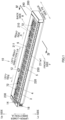
FIG. 1 is a perspective view showing a keyboard instrument according to an embodiment of the present disclosure; -
FIGS. 2A to 2E are perspective views of a case according to the embodiment of the present disclosure, as viewed from a back side thereof, which show individually states in which side cases, a lower case, a front case, and reinforcement members of the case are assembled together; -
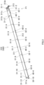
FIG. 3 is a perspective view showing a first reinforcement member according to the embodiment of the present disclosure; -
FIGS. 4A and 4B are partial enlarged perspective views of the first reinforcement member according to the embodiment of the present disclosure, which is viewed from a direction P1 shown inFIG. 3 ; -
FIGS. 5A and 5B are perspective views showing a second reinforcement member of the case according to the embodiment of the present disclosure; -
FIG. 6 is a sectional view of the case according to the embodiment of the present disclosure, which is taken along a line VI-VI inFIG. 2A ; -
FIG. 7 is a sectional view of the case according to the embodiment of the present disclosure, which is taken along a line VII-VII inFIG. 2A ; -
FIG. 8 is a sectional view of the case according to the embodiment of the present disclosure, which is taken along a line VIII-VIII inFIG. 6 ; -
FIG. 9 is a sectional view of the case according to the embodiment of the present disclosure, which is taken along a line IX-IX inFIG. 7 ; -
FIG. 10 is a perspective view of a left side portion of the case according to the embodiment of the present disclosure with a left side case omitted from illustration; and -
FIG. 11 is a perspective view of a right side portion of the case according to the embodiment of the present disclosure with a right side case omitted from illustration. - Hereinafter, an embodiment of the present disclosure will be described based on drawings. A
keyboard instrument 10 shown inFIG. 1 includes a full-scale (88-note)keyboard 5 including pluralwhite keys 3 and pluralblack keys 4, which make up a large number of keys or 88 keys of thekeyboard 5, and acase 200. In the following description, a front to the keys in thekeyboard 5 in a front-back direction FB is referred to as a front side F, and a back to the keys in thekeyboard 5 in the front-back direction FB is referred to as a back side B. When facing thekeyboard 5 from the front side F, a left of thekeyboard 5 is referred to as a left side L, and a right of thekeyboard 5 is referred to as a right side R. In thekeyboard 5, the keys are aligned in a left-right direction LR. When viewing thekeyboard instrument 10 in an upper-lower direction UL thereof, an upper side is referred to as an upper side Up, and a lower side is referred to as a lower side Lo. In the embodiment, while thekeyboard instrument 10 is described as an electronic keyboard instrument, thekeyboard instrument 10 may take other forms. In addition, thecase 200 is not limited to a case for thekeyboard instrument 10 but may be acase 200 for other devices. - As shown in
FIG. 1 , thecase 200 has anupper case 210, alower case 220, aleft side case 230 and aright side case 240 as side cases, and afront case 250. Theupper case 210, thelower case 220, and thefront case 250 are provided in such a manner as to be long in the left-right direction LR, which is one of the directions relating to thekeyboard instrument 10. Theupper case 210 has anupper panel 211 and a back panel (not shown). Theleft side case 230 and theright side case 240, which each have substantially a rectangular shape elongated in the front-back direction FB, are disposed adjacent to left and right end portions of theupper case 210 and thefront case 250, respectively. Thelower case 220 is provided on lower sides Lo of theupper case 210 and the side cases (the left side case 30, the right side case 240) . - A
keyboard installation portion 6 where to install thekeyboard 5 is provided at a front side F of theupper case 210 and between theleft side case 230 and theright side case 240. Thefront case 250, having substantially a platelike shape elongated in the left-right direction LR, is provided at the front side F of thekeyboard 5 and between theleft side case 230 and theright side case 240. - A
rotary knob 12, which is configured to control the volume of thekeyboard instrument 10, is provided on theupper panel 211 of theupper case 210. Acontrol section 14, which includes a pitch modulator, push buttons, and the like, is provided on an upper surface of theleft side case 230. In addition, anearphone jack 18 is provide in a front surface of theleft side case 230. - Hereinafter, connecting structures between the
lower case 220 and thefront case 250 and between thefront case 250 and the side cases (theleft side case 230, the right side case 240) will be described in detail.FIG. 2A shows a state, as viewed from a back side B of thekeyboard instrument 10, in which thelower case 220, the side cases (theleft side case 230, the right side case 240), and thefront case 250 are assembled together by being connected together by areinforcement member 300. Thereinforcement member 300 is divided into plural members, and thefront case 250 is fixed to thereinforcement member 300 while spanning thereinforcement member 300. In the present embodiment, thereinforcement member 300 is divided into afirst reinforcement member 310 and asecond reinforcement member 320, whereby thefirst reinforcement member 310 is provided on the left side L, while thesecond reinforcement member 320 is provided on the right side R. That is, in the present embodiment, thefirst reinforcement member 310 and thesecond reinforcement member 320 are thereinforcement members 300 of theplural reinforcement members 300 which are disposed at end portions in the left-right direction LR. Additionally, thefirst reinforcement member 310 is provided in such a manner as to be longer than thesecond reinforcement member 320, as a result of which thereinforcement member 300 is divided asymmetrically. - The
lower case 220 is formed from a resin material, which constitutes a first material, through injection molding. The reinforcement members 300 (thefirst reinforcement member 310, the second reinforcement member 320) are formed from a sheet of steel, which constitutes a second material, through sheet metal work. A linear expansion coefficient of the second material is smaller than a linear expansion coefficient of the first material. Additionally, thefront case 250 is made up of a wood member, which constitutes a third material. - As shown in
FIG. 3 , thefirst reinforcement member 310 has substantially an L-shape in section and is provided in such a manner as to be long in the left-right direction LR. Thefirst reinforcement member 310 includes afront plate 311 and alower plate 312. Thefront plate 311 has substantially the same width as a width in the upper-lower direction UL (a width direction) of thefront case 250, and thelower plate 312 is bent towards the back side B from a lower edge of thefront plate 311 and is made sufficiently narrower in width than thefront plate 311. Anengagement piece 311a (a first projecting portion) is provided at a right end of thefront plate 311. Theengagement piece 311a is bent towards the front side F into a shape of a tongue piece with plate surfaces thereof made to face the left-right direction LR. A right end of thelower plate 312 projects further in the direction of the right side R than the right end of thefront plate 311. - As shown in
FIGS. 4A and 4B ,engagement pieces front plate 311. Of the two tongue piece-shaped engagement pieces engagement piece 311b (a second projecting portion) is bent towards the front side F with plate surfaces thereof made to face the upper-lower direction UL. As shown in a circled view P2 ofFIG. 4B , theengagement piece 311b is formed substantially into a rectangular shape including an inclined side or portion 311b1 which is formed by gradually inclining an outer side (a side facing theleft side case 230 at the left side L) in such a manner that a projecting end side gets narrower in width. Of the two tongue piece-shapedengagement pieces engagement piece 311c (a first projecting portion) is bent towards the front side F with plate surfaces thereof made to face the left-right direction LR. Theengagement piece 311c is formed substantially into a rectangular shape. - Two
projections 311d (abutment projections), which are aligned vertically, are provided at the left end portion of the front plate 311 (also refer toFIG. 10 ). A recessedgroove portion 311e is provided between the twoprojections 311d in such a manner as to extend from the left side L end portion of thefront plate 311 towards the right side R, whereby the left end portion of thefront plate 311 is reinforced. The recessedgroove portion 311e is recessed from a surface of thefront plate 311 which faces the front side F. In addition, a projectingpiece 311f is provided at the left side L end portion of thefront plate 311 in such a manner as to project upwards therefrom (towards an upper side Up of theprojection 311d) with plate surfaces made to face the front-back direction FB. - A fixing
portion 313 is provided at the left side L end portion of thefront plate 311. The fixingportion 313 is bent towards the back side B from the left side L end portion of thefront plate 311. The fixingportion 313 includes avertical plate 313a, which is disposed in such a manner that plate surfaces thereof are made to face in the left-right direction LR, an upperhorizontal plate 313b, which is bent from an upper end of thevertical plate 313a towards the right side R and is disposed in such a manner that plate surfaces thereof are made to face in the upper-lower direction UL, and a lowerhorizontal plate 313c, which is bent from a lower end of thevertical plate 313a towards the left side L and is disposed in such a manner that plate surfaces thereof are made to face in the upper-lower direction UL. A recessedgroove portion 313e is provided on thevertical plate 313a in such a manner as to continuously connect to the recessedgroove portion 311e of thefront plate 311. Abent portion 313f is provided at a back side B of thevertical plate 313a in such a manner as to be bent substantially at right angles towards the right side R.A projecting piece 313d is provided on the lowerhorizontal plate 313c in such a manner as to be bent substantially at right angles towards the upper side Up (also refer toFIG. 3 ) . A distal end treatment is applied to both the projectingpieces - Plural (12 in the present embodiment) screw holes 31-1 to 31-12 are provided in the
front plate 311 so that screw members 81 (refer toFIGS. 2B, 2D, 2E ) are passed therethrough to fix thefront plate 311 to thefront case 250. Plural (10 in the present embodiment) screw holes 32-1 to 32-10 are provided in thelower plate 312 so thatscrew members 82 are passed therethrough to fix thelower plate 312 to thelower case 220. Back side B edge portions of thelower plate 312 which correspond to the screw holes 32-1 to 32-10 and hole portions 40-1 to 40-4, which will be described later, in thelower plate 312 project slightly towards the back side B. - In the two screw holes 31-1 to 31-12, the two screw holes 31-1, 31-2 are provided at the left side L end portion of the
front plate 311 in such a manner as to be disposed vertically while holding the recessedgroove portion 311e therebetween. On the other hand, the two screw holes 31-11, 31-12 are provided at a right side R end portion of thefront plate 311 in such a manner as to be disposed vertically. The screw holes 31-3 to 31-10 lying between the screw holes 31-1, 31-2, 31-11, 31-12 at the left and right end portions are disposed substantially at equal intervals along a longitudinal direction of thefront plate 311 while being disposed in upper and lower positions alternately. In the plural screw holes 31-1 to 31-12 which are provided in thefront plate 311, the screw holes 31-1, 31-2 at the left side L end portion are formed as circular holes. The remaining screw holes 31-3 to 31-12 are formed as elongate holes which are elongated in the left-right direction LR. The screw holes 31-3 to 31-12, which are the elongate holes, have the same elongate shape. - The screw holes 32-1 to 32-10 provided in the
lower plate 312 are all elongate holes which are elongated in the left-right direction LR. The elongate screw hole 32-6 situated substantially at a central portion in the left-right direction LR of thefront case 250 and thelower case 220 is made shorter in longitudinal length than the other elongate screw holes 32-1 to 32-5 and 32-7 to 32-10. - In addition, a
pin 221 set upright from thelower case 220 is passed through each of the four hole portions 40-1 to 40-4 provided in the lower plate 312 (refer to a view (FIG. 2B ) of a circled portion Q1 inFIG. 2A ). The hole portion 40-3 situated substantially at a central portion in the left-right direction LR of thefront case 250 and thelower case 220 is formed into a circular hole, and the other hole portions 40-1, 40-2, 40-4 are formed into elongate holes. The engagement of the hole portions 40-1 to 40-4 with the correspondingpins 221 restricts a movement of thefirst reinforcement member 310 in the front-back direction FB to thereby position thefirst reinforcement member 310 in the relevant direction, while allowing thefirst reinforcement member 310 to move in the left-right direction LR. - Three screw holes 33-1 to 33-3 are provided in the upper
horizontal plate 313b of the fixingportion 313 in such a manner as to be aligned in the front-back direction FB. The front and back screw holes 33-1, 33-3 are formed into elongate holes which are elongated in the left-right direction LR. The screw hole 33-2 lying between the front and back screw holes 33-1, 33-3 is formed into a circular hole. A screw hole 33-4 is provided in the lowerhorizontal plate 313c of the fixingportion 313 and is formed into a circular hole. - As shown in
FIGS. 5A and 5B , thesecond reinforcement member 320 has substantially an L-shape in section and is provided in such a manner as to extend long in the left-right direction LR. Thesecond reinforcement member 320 is provided sufficiently shorter in length in the left-right direction LR than thefirst reinforcement member 310. Thesecond reinforcement member 320 includes afront plate 321 and alower plate 322. Thefront plate 321 has substantially the same width as a width in the upper-lower direction UL (a width direction) of thefront case 250, and thelower plate 322 is bent towards the back side B from a lower edge of thefront plate 321 and is made sufficiently narrower in width than thefront plate 321. Anengagement piece 321a (a first projecting portion) is provided at a left end of thefront plate 321. Theengagement piece 321a is bent towards the front side F into a shape of a tongue piece with plate surfaces thereof made to face the left-right direction LR. - An
engagement piece 321b having a shape of a tongue piece is provided closer to the left side L than a center of thefront plate 321, and anengagement piece 321c having a shape of a tongue piece is provided closer to the right side R than the center of thefront plate 321. Theengagement piece 321b (a second projecting portion) is bent towards the front side F with plate surfaces thereof made to face the upper-lower direction UL. As shown in a view (FIG. 5B ) of a circled portion P3, theengagement piece 321b is formed substantially into a rectangular shape including an inclined side or portion 321b1 which is formed by gradually inclining an outer side (a side facing theright side case 240 at the right side R) in such a manner that a projecting end side gets narrower in width. Theengagement piece 321c (a first projecting portion) is bent towards the front side F with plate surfaces thereof made to face the left-right direction LR. Theengagement piece 321c is formed substantially into a rectangular shape. - Two
projections 321d (abutment projections), which are aligned vertically, are provided at a right end portion of the front plate 321 (also refer toFIG. 11 ). A recessedgroove portion 321e is provided between the twoprojections 321d in such a manner as to extend in the left-right direction LR for reinforcement of the right end portion of thefront plate 321. The recessedgroove portion 321e is recessed from a surface of thefront plate 321 which faces the front side F. In addition, a projectingpiece 321f is provided at the right side R end portion of thefront plate 321 in such a manner as to project upwards therefrom (towards an upper side Up of theprojection 321d) with plate surfaces thereof made to face the front-back direction FB. - A fixing
portion 323 is provided at the right side R end portion of thefront plate 321. The fixingportion 323 is bent towards the back side B from the right side R end portion of thefront plate 321. The fixingportion 323 includes avertical plate 323a, which is disposed in such a manner that plate surfaces thereof are made to face in the left-right direction LR, an upperhorizontal plate 323b, which is bent from an upper end of thevertical plate 323a towards the left side L and is disposed in such a manner that plate surfaces thereof are made to face in the upper-lower direction UL, and a lowerhorizontal plate 323c, which is bent from a lower end of thevertical plate 323a towards the right side R and is disposed in such a manner that plate surfaces thereof are made to face in the upper-lower direction UL. A recessedgroove portion 323e is provided on thevertical plate 323a in such a manner as to extend in the front-back direction FB to thereby connect to the recessedgroove portion 321e of thefront plate 321 continuously. Abent portion 323f is provided at a back side B of thevertical plate 323a in such a manner as to be bent towards the left side L.A projecting piece 323d is provided on the lowerhorizontal plate 323c in such a manner as to be bent towards the upper side Up while being disposed with plate surfaces thereof made to face the left-right direction LR. A distal end treatment is applied to both the projectingpieces - Plural (four in the present embodiment) screw holes 34-1 to 34-4 are provided in the
front plate 321 so thatscrew members 81 are passed therethrough to fix thefront plate 321 to thefront case 250. Plural (two in the present embodiment) screw holes 35-1 and 35-2 are provided in thelower plate 322 so thatscrew members 82 are passed therethrough to fix thelower plate 322 to thelower case 220. Back side B edge portions of thelower plate 322 which correspond to the screw holes 35-1 and 35-2 and a hole portion 41-1, which will be described later, in thelower plate 322 project slightly towards the back side B. - In the screw holes 34-1 to 34-4, the two screw holes 34-1, 34-2 are provided at the right side R end portion of the
front plate 321 in such a manner as to be disposed vertically while holding the recessedgroove portion 321e therebetween. On the other hand, the two screw holes 34-3, 34-3 are provided at a left side L end portion of thefront plate 321 in such a manner as to be disposed vertically. In the screw holes 34-1 to 34-4 provided in thefront plate 321, the screw holes 34-1, 34-2 on the right side R are formed into circular holes, while the screw holes 34-3, 34-4 on the left side L are formed into elongate holes which are elongated in the left-right direction LR. - The screw holes 35-1 and 35-2 which are provided in the
lower plate 322 are both elongate holes which are elongated in the left-right direction LR. Apin 221 set upright from thelower case 220 is passed through the hole portion 41-1, which is provided between the screw holes 35-1, 35-2 in the left-right direction LR as an elongate hole which is elongated in the left-right direction LR. The engagement of the hole portion 41-1 with thecorresponding pin 221 restricts a movement of thesecond reinforcement member 320 in the front-back direction FB to thereby position thesecond reinforcement member 320 in the relevant direction, while allowing thesecond reinforcement member 320 to move in the left-right direction LR. - Three screw holes 36-1 to 36-3 are provided in the upper
horizontal plate 323b of the fixingportion 323 in such a manner as to be aligned in the front-back direction FB. The front and back screw holes 36-1, 36-3 are formed into elongate holes which are elongated in the left-right direction LR. The screw hole 36-2 lying between the front and back screw holes 36-1, 36-3 is formed into a circular hole. A screw hole 36-4 is provided in the lowerhorizontal plate 323c of the fixingportion 323 and is formed into a circular hole. - An attachment relationship between the reinforcement members 300 (the
first reinforcement member 310, the second reinforcement member 320), and thefront case 250 and thelower case 220 will be described. As shown inFIGS. 6 and7 in which the reinforcement members 300 (the first andsecond reinforcement members 310, 320), thefront case 250, and thelower case 220 are shown in section, an upper end of thefront case 250 projects towards the back side B, and thefront plates first reinforcement member 310, the second reinforcement member 320) are attached to thefront case 250 in such a manner that thefront plates front case 250 in a face-to-face fashion below the upper end of thefront case 250. In addition, a lower end of thefront case 250 is provided in a step-like fashion. - As shown in
FIGS. 2A to 2E (in particular, views (FIGS. 2B, 2D, 2E ) of circled portions Q1, Q3, Q4), thescrew members 81, which are wood screws, are passed through the screw holes 31-1 to 31-12 in thefront plate 311 of thefirst reinforcement member 310 and the screw holes 34-1 to 34-4 in thefront plate 321 of thesecond reinforcement member 320 so as to be tightly screwed into thefront case 250 for fastening. In addition, thescrew members 82, which are machine screws, are passed through the screw holes 32-1 to 32-10 in thelower plate 312 of thefirst reinforcement member 310 and the screw holes 35-1, 35-2 in thelower plate 322 of thesecond reinforcement member 320 so as to be screwed into internally threaded portions which are provided correspondingly to the screw holes 32-1 to 32-10 and 35-1, 35-2 in thelower case 220 for attachment. - As shown in the view (
FIG. 2B ) of the circled portion Q1 inFIG. 2A , a concave engagement target recessed portion 251 (a first recessed portion) is provided on thefront case 250 in such a manner as to be elongated in the left-right direction LR so as to correspond in position and shape to theengagement piece 311c of thefirst reinforcement member 310. The engagement target recessedportion 251 is sized slightly larger widthwise (in the upper-lower direction UL) than a width of theengagement piece 311c. As a result, the engagement of theengagement piece 311c with the engagement target recessedportion 251 allows for a movement of theengagement piece 311c in the left-right direction LR and restricts a movement of theengagement piece 311c in the upper-lower direction UL. Thus, thefront case 250 is positioned in place with respect to thefirst reinforcement member 310 in the upper-lower direction UL, while theengagement piece 311c is allowed to move in the left-right direction LR. - As shown in a view (
FIG. 2C ) of a circled portion Q2 inFIG. 2A , a substantially rectangular concave engagement target recessed portion 252 (a second recessed portion) is provided on thefront case 250 in such a manner as to correspond to theengagement piece 311b of thefirst reinforcement member 310. In addition, as shown inFIG. 10 , a flat surface at a left end of thefront case 250 comes into abutment with theprojections 311d and the projectingpiece 311f of thefront plate 311. Thefront case 250 is positioned with respect to thefirst reinforcement member 310 in the left-right direction LR by theprojections 311d. In attaching thefront case 250 to thefirst reinforcement member 310, the left end of thefront case 250 is brought into abutment with theprojections 311d, and the engagement target recessedportion 252 is pushed onto theengagement piece 311b, whereby the inclined portion 311b1 of theengagement piece 311b bites into a wall surface of the engagement target recessedportion 252 which faces the inclined portion 311b1. In this way, thefront case 250 is not only positioned with respect to thefirst reinforcement member 310 but also is restricted from moving easily with respect to thefirst reinforcement member 310. - As shown in the view (
FIG. 2E ) of the circled portion Q4 inFIG. 2A , a concave engagement target recessed portion 253 (a first recessed portion) is provided on thefront case 250 in such a manner as to be elongated in the left-right direction LR so as to correspond to theengagement piece 321c of thesecond reinforcement member 320. The engagement target recessed portion 25 is sized slightly larger widthwise (the upper-lower direction UL) than a width of theengagement piece 321c. The engagement of theengagement piece 321c with the engagement target recessedportion 253 allows for a movement of theengagement piece 321c in the left-right direction LR and restricts a movement of theengagement piece 321c in the upper-lower direction UL. As a result, thefront case 250 is positioned with respect to thesecond reinforcement member 320 in the upper-lower direction UL. - As shown in the view (
FIG. 2D ) of the circled portion Q3 inFIG. 2A , a substantially rectangular concave engagement target recessed portion 254(a second recessed portion) is provided on thefront case 250 in such a manner as to correspond to theengagement piece 321b of thesecond reinforcement member 320. In addition, as shown inFIG. 11 , a flat surface at a right end of thefront case 250 comes into abutment with theprojections 321d and the projectingpiece 321f of thefront plate 321. Thefront case 250 is positioned with respect to thesecond reinforcement member 320 in the left-right direction LR by theprojections 321d. In attaching thefront case 250 to thesecond reinforcement member 320, the right end of thefront case 250 is brought into abutment with theprojections 321d, and the engagement target recessedportion 252 is pushed onto theengagement piece 321b, whereby the inclined portion 321b1 of theengagement piece 321b bites into a wall surface of the engagement target recessedportion 254 which faces the inclined portion 321b1. In this way, thefront case 250 is not only positioned with respect to thesecond reinforcement member 320 but also is restricted from moving easily with respect to thesecond reinforcement member 320. - In addition, as shown in the view (
FIG. 2D ) of the circled portion Q3 inFIG. 2A , therespective engagement pieces first reinforcement member 310 and thesecond reinforcement member 320 are both brought into engagement with an engagement target recessed portion 255 (a first recessed portion) which is provided on thefront case 250 in such a manner as to be elongated in the left-right direction LR so as to correspond to theengagement pieces portion 255 is made slightly larger than a size (width) in the upper-lower direction UL of theengagement pieces front case 250 is positioned with respect to thefirst reinforcement member 310 and thesecond reinforcement member 320 in the upper-lower direction UL. - A right end of the
first reinforcement member 310 and a left end of thesecond reinforcement member 320 constitute a dividing position where thereinforcement members 300 are divided, and a predetermined gap is defined between the right end of thefirst reinforcement member 310 and the left end of thesecond reinforcement member 320. A gap S1 defined between thefront plates lower plates - As shown in
FIG. 6 ,screw members 83 are passed through the front and back screw holes 33-1, 33-3 (refer toFIG. 4A ) and are then screwed into corresponding internally threaded portions which are provided in aboss 222 set upright from thelower case 220, whereby the upperhorizontal plate 313b of the fixingportion 313 of thefirst reinforcement member 310 is fixed to thelower case 220. On the other hand, as shown inFIG. 8 , ascrew member 84 is passed through the screw hole 33-2, which is disposed between the front and back screw holes 33-1, 33-3 in the upperhorizontal plate 313b, from the lower side Lo and is then screwed into a member making up theleft side case 230, whereby the upperhorizontal plate 313b is fixed to theleft side case 230. In addition, ascrew member 85 is passed through the screw hole 33-4 in the lowerhorizontal plate 313c from the lower side Lo via thelower case 220 and is then screwed into a member making up theleft side case 230, whereby the lowerhorizontal plate 313c is fixed to theleft side case 230. In this way, theleft side case 230 is fixed to one end of thefirst reinforcement member 310. Ahole portion 224 in thelower case 220 through which thescrew member 85 is passed is formed into an elongate hole which is elongated long in the left-right direction LR. An inner surface (a surface facing the right side R) of the projectingpiece 313d of the lowerhorizontal plate 313c comes close to or into contact with aprojection 231, which is provided on theleft side case 230 in such a manner as to project towards the lower side Lo, whereby thefirst reinforcement 310 is positioned with respect to theleft side case 230 in the left-right direction LR. - As shown in
FIG. 7 ,screw members 83 are passed individually through the front and back screw holes 36-1, 36-3 (refer toFIG. 4A ) and are then screwed into corresponding internally threaded portions which are provided in aboss 223 set upright from thelower case 220, whereby the upperhorizontal plate 323b of the fixingportion 323 of thesecond reinforcement member 320 is fixed to thelower case 220. On the other hand, as shown inFIG. 9 , ascrew member 84 is passed through the screw hole 36-2, which is disposed between the front and back screw holes 36-1, 36-3 in the upperhorizontal plate 323b, from the lower side Lo and is then screwed into a member making up theright side case 240, whereby the upperhorizontal plate 323b is fixed to theright side case 240. In addition, ascrew member 85 is passed through the screw hole 33-4 in the lowerhorizontal plate 323c from the lower side Lo and is then screwed into a member making up theright side case 240, whereby the lowerhorizontal plate 323c is fixed to theright side case 240. In this way, theright side case 240 is fixed to one end of thesecond reinforcement member 320. Ahole portion 224 in thelower case 220 through which thescrew member 85 is passed is formed into an elongate hole which is elongated in the left-right direction LR. An inner surface (a surface facing the left side L) of the projectingpiece 323d of the lowerhorizontal plate 323c comes close to or into contact with aprojection 241, which is provided on theright side case 240 in such a manner as to project towards the lower side Lo, whereby thesecond reinforcement 320 is positioned with respect to theright side case 240 in the left-right direction LR. - A relationship will be described below which will be established between the
reinforcement members 300 and thefront case 250, thelower case 220, and the side cases to deal with an expansion(or extension) and a contraction of thelower case 220 and thefront case 250 as the outside air temperatures change. For example, when the outside air temperatures rise, thelower case 220, which is made from the resin material, expands, while thefront case 250, which is made of the wood member, contracts due to a drop in humidity which follows the rise in the outside air temperatures. When the outside air temperatures lower, thelower case 220 contracts, while thefront case 250 expands. On the other hand, the expansion and the contraction of the reinforcement members 300 (thefirst reinforcement member 310, the second reinforcement member 320) is sufficiently small compared with thelower case 220 and thefront case 250 for a normal change in outside air temperatures because thereinforcement members 300 are made of the sheet metal members. - The fixing
portions first reinforcement member 310, the second reinforcement member 320) are fixed to the corresponding side cases (theleft side case 230, the right side case 240) via the circular screw holes 33-2, 33-4, 36-2, 36-4. As a result, thefirst reinforcement member 310 and thesecond reinforcement member 320 are fixed to the corresponding side cases (theleft side case 230, the right side case 240) so as to be restricted from moving relative to the relevant side cases. - In the
first reinforcement member 310, theengagement piece 311b having the inclined portion 311b1 is disposed closer to theleft side case 230 than the elongate screw hole 31-3 which lies nearest to theleft side case 230. Further, thefirst reinforcement member 310 and thefront case 250 are fixed to each other via the circular screw holes 31-1, 31-2 at a portion of thefirst reinforcement member 310 which lies closer to theleft side case 230 than theengagement piece 311b. As a result, thefirst reinforcement member 310 and thefront case 250 are fixed together so as not to allow for a relative movement at the portion in the vicinity of the left side end portion of thefront case 250. That is, a gap defined between thefront case 250 and theleft side case 230 does not change even though thefront case 250 expands or contracts. On the other hand, thefirst reinforcement member 310 and thefront case 250 are fixed to each other via the elongate screw holes 31-3 to 31-12 at a portion of thefirst reinforcement member 310 which lies closer to an inner side (the right side R) than theengagement piece 311b, as a result of which, as will be described later, thefirst reinforcement member 310 and thefront case 250 are fixed together so as to allow for a relative movement. - Similarly, also in the
second reinforcement member 320, theengagement piece 321b having the inclined portion 321b1 is disposed closer to theright side case 240 than the elongate screw holes 34-3, 34-4 which lie nearest to theright side case 240. As a result, a gap defined between theright side case 240 and thefront case 250 does not change. That is, thesecond reinforcement member 320 and thefront case 250 are fixed to each other so as to restrict a relative movement at a portion of thesecond reinforcement member 320 which lies in the vicinity of the right side end portion of thefront case 250, while thesecond reinforcement member 320 and thefront case 250 are fixed to each other so as to allow for a relative movement at a portion of thesecond reinforcement member 320 which lies closer to an inner side (the left side L) than theengagement piece 321b. - On the other hand, the reinforcement members 300 (the
first reinforcement member 310, the second reinforcement member 320) are fixed to thelower case 220 via the elongate screw holes 32-1 to 32-10, 35-1, 35-2. The reinforcement members 300 (thefirst reinforcement member 310, the second reinforcement member 320) are fixed to thelower case 220 via the elongate screw holes 33-1, 33-3, 36-1, 36-3 also at the fixingportions first reinforcement member 310, the second reinforcement member 320) are allowed to move relative to thelower case 220. That is, when thelower case 220 expands or contracts due to a change in outside air temperatures, lower surfaces of head portions of thescrew members 82 which are installed in the elongate screw holes 32-1 to 32-10, 35-1, 35-2, 33-1, 33-3, 36-1, 36-3 slide over surfaces of thelower plates horizontal plates horizontal plates first reinforcement member 310, the second reinforcement member 320) are allowed to move relative to thelower case 220. - Similarly, flange portions of head portions of the
screw members 81 slide over thefront plates first reinforcement member 310, the second reinforcement member 320) are fixed to thefront case 250 via the elongate screw holes 31-3 o 31-12, 34-3, 34-4 in thefront plates - Consequently, for example, when the outside air temperatures rise, causing the
front case 250 to contract, theleft side case 230 and thefirst reinforcement member 310 move to the right side R, and theright side case 240 and thesecond reinforcement member 320 move to the left side L. Then, the predetermined gaps S1, S2 decrease which are defined at the dividing portion where thefirst reinforcement member 310 and thesecond reinforcement member 320 are divided. In addition, as this occurs, although thelower case 220 extends in the left-right direction LR, since thefirst reinforcement member 310 and thesecond reinforcement member 320 are allowed to move relative to thelower case 220, there is generated no forced strain in thelower case 220. When the outside air temperatures lower, the relevant members expand or contact reversely to what is described above. - Thus, the gaps between the left and right ends of the
front case 250 and the side cases (theleft side case 230, the right side case 240) remain constant at all times even the outside air temperatures change. As a result, the gaps between thefront case 250 and the side cases, which constitute portions visible from the player, do not change, thereby making it possible to secure a high aesthetic design. - The
lower case 220 and the side cases (theleft side case 230, the right side case 240) are connected together via the elongate screw holes (for example, the hole portion 224) which are elongated in the left-right direction LR, and predetermined gaps S3, S4 are provided between thelower case 220 and the side cases (theleft side case 230, the right side case 240) in a lower surface of thecase 200, whereby the side cases (theleft side case 230, the right side case 240) are not restricted from moving by thelower case 220. In addition, since the gaps S3, S4 are provided in the lower surface of thecase 200, there is caused no risk of the player happening to see those gaps. - In addition, a substantially central portion in the left-right direction LR of the
case 200 is affected little by the expansion or contraction of thelower case 220 and thefront case 250, as a result of which the screw hole 32-6 (disposed in thelower plate 312 of the first reinforcement member 310) in the position corresponding to the relevant central portion is formed shorter in length in the left-right direction LR than the other screw holes disposed in the other positions in thelower plate 312. Similarly, the hole portion 40-3 is formed into a circular hole. - The dividing position (the view (
FIG. 2D ) of the circled portion Q3 inFIG. 2A ) of thereinforcement members 300 is disposed closer to the right side R so as to avoid the substantially central portion in the left-right direction LR of thecase 200, whereby the rigidity at the substantially central portion in the left-right direction LR of thecase 200 is enhanced. In addition, since theleft side case 230 on which thecontrol section 14 is disposed becomes heavier in weight than theright side case 240 on which no control section or the like is disposed, the rigidity of theleft side case 230, which is heavier in weight, can be enhanced by disposing the dividing position of thereinforcement members 300 closer to the right side R in thecase 200. - Although not shown, by dividing the back panel as required in the left-right direction LR, the
lower case 220 and the back panel are prevented from imposing any influence on the behaviors of thefront case 250, the side cases (theleft side case 230, the right side case 240), and thelower case 220. - Thus, in the embodiment of the present disclosure, the
case 200 includes thelower case 220 made from the resin material which constitutes the first material and extended to be long in the left-right direction LR which is the one direction, the plural reinforcement members 300 (thefirst reinforcement member 310, the second reinforcement member 320) fixed to thelower case 220, made from the sheet of steel which constitutes the second material whose linear expansion coefficient is smaller than the linear expansion coefficient of the first material (the resin material) and disposed while being divided in the left-right direction LR, thefront case 250 formed in such a manner as to be long in the one direction and fixed to theplural reinforcement members 300 in such a manner as to span thereinforcement members 300, and the side cases (theleft side case 230, the right side case 240) disposed adjacent to thefront case 250 and fixed to the ends of thereinforcement members 300. - By adopting the configuration described above, even though the
front case 250 and thelower case 220 expand or contract differently in amount due to the different linear expansion coefficients thereof as the outside air temperatures change, the dividedreinforcement members 300 move in synchronism with the side cases and thefront case 250, and the gaps defined between the side cases and thefront case 250 remain constant. Thus, even though parts of different materials like thefront case 250 and thelower case 220 are assembled together, there is caused no risk of the external appearance being deteriorated or the constituent members being damaged. - In addition, the
plural reinforcement members 300 are divided asymmetrically. As a result, the dividing position can be set in accordance with a desired reinforcement target location. - The
reinforcement members 300 in theplural reinforcement members 300 which are disposed at the end portions in the one direction, that is, thefirst reinforcement member 310 and thesecond reinforcement member 320 in the present embodiment in which the reinforcement members are divided into the two members are fixed to thefront case 250 and the side cases in such a manner as to restrict the relative movement and are fixed to thelower case 220 in such a manner as to allow for the relative movement. Specifically speaking, the circular screw holes are provided at the portions at which the relative movement is restricted, and the elongate screw holes are provided at the portions at which the reinforcement members are fixed in such a manner as to allow for the relative movement. As a result, the side cases are allowed to move in synchronism with thereinforcement members 300 which are disposed at the end portions as thefront case 250 expands (or extends) or contracts. - In addition, the
reinforcement members 300 disposed at the end portions in the one direction include the circular screw holes 31-1, 31-2, 34-1, 34-2, 33-2, 33-4, 36-2, 36-4 through which the screw members are passed for thereinforcement members 300 to be fixed to thefront case 250 and the side cases, the elongate screw holes 31-3 to 31-12, 34-3, 34-4 through which the screw members are passed for thereinforcement members 300 to be fixed to thefront case 250, and the elongate screw holes 32-1 to 32-10, 35-1, 35-2 through which the screw members are passed for thereinforcement member 300 to be fixed to thelower case 220. As a result, the relative movement can be restricted or allowed with the simple configuration. - In addition, the
reinforcement members 300 have the first projecting portions (theengagement pieces front case 250 have the first recessed portions (the engagement target recessedportions reinforcement members 300 can deal properly with expansion or contraction in the left-right direction LR of thefront case 250 which is triggered by a change in outside air temperatures while thereinforcement members 300 and thefront case 250 can be positioned with respect to each other in the upper-lower direction UL. - The
reinforcement members 300 have the tongue piece-shaped second projecting portions (theengagement pieces reinforcement members 300 are fixed, and thefront case 250 has the second recessed portions (the engagement target recessedportions 252, 254) which are brought into engagement with the second projecting portions. As a result, thereinforcement members 300 can be positioned in the left-right direction LR at the portions in the vicinity of both the end portions of thefront case 250 together with the circular screw holes 31-1, 31-2, 34-1, 34-2. - In addition, the
reinforcement members 300 include the abutment projections (theprojections front case 250. As a result, the positioning of thefront case 250 with respect to thereinforcement members 300 can be facilitated. - Then, the
keyboard instrument 10 includes thecase 200. As a result, thekeyboard instrument 10 can be provided which reduces the risk of the external appearance being deteriorated or the constituent members being damaged due to a change in outside air temperatures even though the members of the different materials are assembled together. - In the description that has been made heretofore, while the present disclosure has been described based on the relative movements triggered by a change in outside air temperatures to happen among the
reinforcement members 300, thefront case 250, thelower case 220, and the side cases (theleft side case 230, the right side case 240), the present disclosure can also reduce the risk of the external appearance being deteriorated or the constituent members being damaged by a change in external environments (for example, humidity) other than outside air temperatures. - In addition, in the
case 200 of the present disclosure, thelower case 220 is formed from the resin material which constitutes the first material, and thefront case 250 is formed from the wood member which constitutes the third material. The reason that this configuration is adopted is that in the case that both thelower case 220 and thefront case 250 are formed from wood members, it will be difficult to realize a reduction in weight and cost of thecase 200, while in the case that both thelower case 220 and thefront case 250 are formed from plastics, there will be caused a risk of the quality of thecase 200 being deteriorated. Thus, it is preferable that thelower case 220 to which any attention is hardly paid is formed from the resin material, while thefront case 250 to which much attention is paid easily is formed from the wood member. - In the existing techniques, in many cases, the
front case 250 and the side cases (theleft side case 230, the right side case 240) are fixed to thelower case 220. In this case, when thefront case 250 formed from the wood member expands and thelower case 220 formed from the resin material contracts as a result of a change in external environments (for example, a drop in outside air temperatures), the side cases (theleft side case 230, the right side case 240) are pushed out laterally in the left-right direction LR. Thereafter, when thefront case 250 contracts and thelower case 220 expands as the external environments change further, the lateral end positions of thekeyboard 5 are not restored to the original positions thereof because the side cases and the front case are not connected directly to each other, whereby a gap is produced between the side cases and the front case to such an extent that the side cases are pushed out laterally. When the front frame and the lateral end of thekeyboard 5 are attempted to be connected directly to each other by fastening them together by driving a screw in a lateral direction to solve the problem described above, the opposite lateral end of thekeyboard 5 constitutes an obstacle, making the operation difficult to be executed. Then, when attempting to drive a screw in the lateral direction from an outside, a head of the screw so driven becomes visible from the outside. The present disclosure can provide thekeyboard instrument 10 which can reduce the risk of the external appearance being deteriorated which would otherwise be the case when the outside air temperatures change even though the members of the different materials are assembled together, and which can be built up without any difficulty. - While the embodiment of the present disclosure has been described heretofore, the embodiment is presented as the example, and hence, there is no intention to limit the scope of the present invention by the embodiment. The novel embodiment can be carried out in other various forms, and various omissions, replacements and modifications can be made thereto without departing from the spirit and scope of the present invention. Those resulting embodiments and modified examples thereof are included in the scope and gist of the present invention and are also included in the scope of inventions claimed for patent under claims below and their equivalents.
Claims (15)
- A case (200) comprising;a lower case (220) formed from a first material and extended long in a first direction (LR);plural reinforcement members (310, 320) fixed to the lower case (220), made from a second material whose linear expansion coefficient is smaller than a linear expansion coefficient of the first material, and disposed to be divided in the first direction (LR);a front case (250) formed in such a manner as to extend long in the first direction (LR) and fixed to each of the plural reinforcement members (310, 320); andside cases (230, 240) disposed adjacent to the front case (250) and fixed individually to ends of the reinforcement members (310, 320).
- The case (200) according to claim 1,
wherein the plural reinforcement members (310, 320) are divided asymmetrically. - The case (200) according to claim 1,
wherein the plural reinforcement members (310, 320) are divided so as to define predetermined intervals therebetween. - The case (200) according to claim 1,
wherein the front case (250) is formed from a third material configured to deform in an opposite direction to a direction in which the lower case (220) deforms as an external environment changes. - The case (200) according to claim 1,wherein the first material is a resin or a plastic, andwherein the second material is a metal.
- The case (200) according to claim 4,wherein the first material is a resin or a plastic,wherein the second material is a metal, andwherein the third material is wood.
- The case (200) according to claim 1,
wherein of the plural reinforcement members (310, 320), the reinforcement member (310, 320) which is disposed at an end portion in the first direction (LR) comprises a portion at which the reinforcement member (310, 320) is fixed to the front case (250) in such a manner as to allow for a relative movement and a portion at which the reinforcement member (310, 320) is fixed to the front case (250) in such a manner as to restrict a relative movement, is fixed to the side case (230, 240) in such a manner as to restrict a relative movement, and is fixed to the lower case (220) in such a manner as to allow for a relative movement. - The case (200) according to claim 1,
wherein the reinforcement member (310, 320) which is disposed at the end portion in the first direction (LR) comprises a circular screw hole (31-1, 31-2, 34-1, 34-2, 33-2, 33-4, 36-2, 36-4) through which a screw member is passed for the reinforcement member (310, 320) to be fixed to the front case (250) and the side case (230, 240), an elongate screw hole (31-3 to 31-12, 34-3, 34-4) through which a screw member is passed for the reinforcement member (310, 320) to be fixed to the front case, and an elongate screw hole (32-1 to 32-10, 35-1, 35-2) through which a screw member is passed for the reinforcement member (310, 320) to be fixed to the lower case. - The case (200) according to claim 1,wherein the reinforcement member (300) comprises a first projecting portion (311a, 311c, 321a, 321c) having a shape of a tongue piece,wherein the front case (250) comprises a first recessed portion (251, 255, 253) configured to be brought into engagement with the first projecting portion, andwherein an engagement of the first projecting portion (311a, 311c, 321a, 321c) with the first recessed portion (251, 255, 253) restricts a movement of the first projecting portion (311a, 311c, 321a, 321c) in a second direction (UL) which is at right angles to the first direction (LR) and allows for a movement of the first projecting portion (311a, 311c, 321a, 321c) in the first direction (LR).
- The case (200) according to claim 1,wherein the reinforcement member (300) comprises a second projecting portion (311b, 321b) having a shape of a tongue piece, andwherein the front case (250) comprises a second recessed portion (252, 254) configured to be brought into engagement with the second projecting portion (311b, 321b).
- The case (200) according to claim 10,
wherein the second projecting portion (311b, 321b) has a substantially rectangular shape comprising an inclined portion (311b1, 321b1) which is formed by inclining a side of the second projecting portion (311b, 321b) which faces the side case (230, 240) to which the reinforcement member (300) is fixed in such a manner that a projecting end side gets narrower in width. - The case (200) according to claim 1,
wherein the reinforcement member (300) comprises an abutment projection (311d, 321d) configured to be brought into abutment with an end face in the first direction (LR) of the front case (250). - The case (200) according to claim 1,
wherein the plural reinforcement members (310, 320) are provided individually at both end portions in the first direction (LR) of the front case (250) in such a manner as to move in opposite directions as the front case (250) deforms. - The case (200) according to claim 1,wherein the reinforcement member (310, 320) comprises a front plate (311, 321) having substantially an equal width to a width of the front case (250) defined in a second direction (UL) which is at right angles to the first direction (LR) and a lower plate (312, 322) bent from a lower edge of the front plate (311, 321) towards a back side (B) and having a width which is sufficiently narrower than the width of the front case (311, 321), andwherein a first projecting portion (311a, 321a) which is formed by being bent towards a front side (F) into a shape of a tongue piece is provided at an end of the front plate (311, 321) which lies farther away from the side case (230, 240) to which the reinforcement (310, 320) is fixed.
- A keyboard instrument (10) comprising the case (200) according to claim 1.
Applications Claiming Priority (1)
| Application Number | Priority Date | Filing Date | Title |
|---|---|---|---|
| JP2022048490A JP7452566B2 (en) | 2022-03-24 | 2022-03-24 | Cases and keyboard instruments |
Publications (2)
| Publication Number | Publication Date |
|---|---|
| EP4250283A1 true EP4250283A1 (en) | 2023-09-27 |
| EP4250283B1 EP4250283B1 (en) | 2025-10-29 |
Family
ID=85726449
Family Applications (1)
| Application Number | Title | Priority Date | Filing Date |
|---|---|---|---|
| EP23163106.0A Active EP4250283B1 (en) | 2022-03-24 | 2023-03-21 | Case and keyboard instrument |
Country Status (4)
| Country | Link |
|---|---|
| US (2) | US12437738B2 (en) |
| EP (1) | EP4250283B1 (en) |
| JP (2) | JP7452566B2 (en) |
| CN (1) | CN116805479A (en) |
Families Citing this family (7)
| Publication number | Priority date | Publication date | Assignee | Title |
|---|---|---|---|---|
| JP2022084995A (en) * | 2020-11-27 | 2022-06-08 | 株式会社三洋物産 | Pachinko machine |
| JP7452566B2 (en) * | 2022-03-24 | 2024-03-19 | カシオ計算機株式会社 | Cases and keyboard instruments |
| JP1771141S (en) * | 2023-06-21 | 2024-05-23 | Electronic piano | |
| JP1771142S (en) * | 2023-06-21 | 2024-05-23 | Electronic piano | |
| USD1078839S1 (en) * | 2023-06-25 | 2025-06-10 | Shenzhen Telunsi Musical Instruments Co., Ltd. | Portable piano |
| USD1026079S1 (en) * | 2023-06-25 | 2024-05-07 | Shenzhen Telunsi Musical Instruments Co., Ltd. | Foldable piano |
| USD1026080S1 (en) * | 2023-09-15 | 2024-05-07 | Shenzhen Telunsi Musical Instruments Co., Ltd. | Foldable piano |
Citations (5)
| Publication number | Priority date | Publication date | Assignee | Title |
|---|---|---|---|---|
| JPH0790817A (en) * | 1993-09-24 | 1995-04-04 | Nippon Light Metal Co Ltd | Translucent soundproof panel |
| US20130074683A1 (en) * | 2011-09-28 | 2013-03-28 | Kabushiki Kaisha Kawai Gakki Seisakusho | Keyboard device for electronic keyboard instrument and mounting structure of let-off imparting member for electronic keyboard instrument |
| CN110675842A (en) * | 2019-10-12 | 2020-01-10 | 福建艾维尔科技有限公司 | Piano central disc of resistance to deformation |
| JP2020034718A (en) * | 2018-08-30 | 2020-03-05 | 株式会社河合楽器製作所 | Before the reed of the keyboard instrument |
| FR3100366A1 (en) * | 2019-09-04 | 2021-03-05 | Adele H. | Electronic piano |
Family Cites Families (19)
| Publication number | Priority date | Publication date | Assignee | Title |
|---|---|---|---|---|
| JPS5750849Y2 (en) * | 1976-02-27 | 1982-11-06 | ||
| JP2000276167A (en) | 1999-01-19 | 2000-10-06 | Yamaha Corp | Body structure of stringed instrument |
| CN101515450B (en) | 2003-09-12 | 2013-07-24 | 雅马哈株式会社 | Key structure and keyboard apparatus |
| JP4385781B2 (en) * | 2004-02-06 | 2009-12-16 | ヤマハ株式会社 | Keyboard device |
| JP4929945B2 (en) | 2006-09-21 | 2012-05-09 | ヤマハ株式会社 | Keyboard device |
| US7902445B2 (en) * | 2006-12-27 | 2011-03-08 | Yamaha Corporation | Housing structure of electronic keyboard musical instrument |
| US7709717B2 (en) * | 2007-01-05 | 2010-05-04 | Yamaha Corporation | Structure for electronic keyboard instrument |
| JP5186882B2 (en) * | 2007-11-01 | 2013-04-24 | ヤマハ株式会社 | Electronic musical instrument keyboard device |
| JP5589280B2 (en) * | 2008-12-22 | 2014-09-17 | ヤマハ株式会社 | Electronic musical instrument housing structure |
| JP5532670B2 (en) * | 2009-04-30 | 2014-06-25 | ヤマハ株式会社 | Electronic keyboard instrument |
| JP5469976B2 (en) | 2009-09-28 | 2014-04-16 | 株式会社河合楽器製作所 | Electronic keyboard instrument keyboard device |
| JP6414796B2 (en) | 2013-09-19 | 2018-10-31 | カシオ計算機株式会社 | Electronic keyboard instrument |
| JP6667136B2 (en) * | 2016-01-20 | 2020-03-18 | カシオ計算機株式会社 | Equipment cases, electronic devices and electronic musical instruments |
| JP2020016670A (en) | 2016-10-31 | 2020-01-30 | ヤマハ株式会社 | Electronic keyboard musical instrument |
| US11072928B2 (en) * | 2019-03-28 | 2021-07-27 | Duo-Gard Industries, Inc. | Thermally adaptive glazing panel roofing system |
| JP7194342B2 (en) * | 2021-02-25 | 2022-12-22 | カシオ計算機株式会社 | equipment and electronic musical instruments |
| EP4202917B1 (en) * | 2021-12-22 | 2024-10-16 | Casio Computer Co., Ltd. | Sound radiation appratus, electronic musical instrument, and sound radiation appratus fabrication method |
| JP7452566B2 (en) * | 2022-03-24 | 2024-03-19 | カシオ計算機株式会社 | Cases and keyboard instruments |
| JP2025004387A (en) * | 2023-06-26 | 2025-01-15 | カシオ計算機株式会社 | Lids and keyboard instruments |
-
2022
- 2022-03-24 JP JP2022048490A patent/JP7452566B2/en active Active
-
2023
- 2023-03-15 CN CN202310246926.8A patent/CN116805479A/en active Pending
- 2023-03-21 EP EP23163106.0A patent/EP4250283B1/en active Active
- 2023-03-23 US US18/125,414 patent/US12437738B2/en active Active
-
2024
- 2024-03-06 JP JP2024034211A patent/JP7845394B2/en active Active
-
2025
- 2025-09-03 US US19/317,752 patent/US20260004761A1/en active Pending
Patent Citations (5)
| Publication number | Priority date | Publication date | Assignee | Title |
|---|---|---|---|---|
| JPH0790817A (en) * | 1993-09-24 | 1995-04-04 | Nippon Light Metal Co Ltd | Translucent soundproof panel |
| US20130074683A1 (en) * | 2011-09-28 | 2013-03-28 | Kabushiki Kaisha Kawai Gakki Seisakusho | Keyboard device for electronic keyboard instrument and mounting structure of let-off imparting member for electronic keyboard instrument |
| JP2020034718A (en) * | 2018-08-30 | 2020-03-05 | 株式会社河合楽器製作所 | Before the reed of the keyboard instrument |
| FR3100366A1 (en) * | 2019-09-04 | 2021-03-05 | Adele H. | Electronic piano |
| CN110675842A (en) * | 2019-10-12 | 2020-01-10 | 福建艾维尔科技有限公司 | Piano central disc of resistance to deformation |
Also Published As
| Publication number | Publication date |
|---|---|
| JP2024063205A (en) | 2024-05-10 |
| US20230306939A1 (en) | 2023-09-28 |
| EP4250283B1 (en) | 2025-10-29 |
| JP2023141910A (en) | 2023-10-05 |
| JP7452566B2 (en) | 2024-03-19 |
| US20260004761A1 (en) | 2026-01-01 |
| CN116805479A (en) | 2023-09-26 |
| US12437738B2 (en) | 2025-10-07 |
| JP7845394B2 (en) | 2026-04-14 |
Similar Documents
| Publication | Publication Date | Title |
|---|---|---|
| EP4250283B1 (en) | Case and keyboard instrument | |
| US9247658B2 (en) | Locking enclosure, stiffening ring, and vertical mounting stiffeners for securing components | |
| US12315481B2 (en) | Keyboard instrument | |
| US8132869B2 (en) | Fastening device and a computer case having the fastening device | |
| US10917977B2 (en) | Connector for joining two housing parts, and a housing including two housing parts and at least one connector | |
| KR101976432B1 (en) | Coupling device of electronic device | |
| JP6867205B2 (en) | Cover mounting structure and display device | |
| US11089172B2 (en) | Image forming apparatus | |
| US6087575A (en) | Keyboard device for keyboard-based musical instrument | |
| US7659470B2 (en) | Housing structure of electronic keyboard musical instrument | |
| JP3121556B2 (en) | Frame material mounting bracket | |
| JP6858638B2 (en) | Protective cover connector and its assembly structure | |
| US12221990B2 (en) | Fastener assembly for blind mounting | |
| JPH0733950B2 (en) | Refrigerator door | |
| US10718366B1 (en) | Connecting structure | |
| WO2020174830A1 (en) | Cable guide and wire harness device | |
| KR101158363B1 (en) | Fabricated box kit | |
| US7709717B2 (en) | Structure for electronic keyboard instrument | |
| JP3670485B2 (en) | Keyboard device for keyboard instrument | |
| US20130038185A1 (en) | Enclosure, stiffening ring, and vertical mounting stiffeners for securing components | |
| KR100506915B1 (en) | Cover Structure of Scuff Trim for Door | |
| CN210607724U (en) | Conjoined panel and switch socket | |
| EP4523937A1 (en) | Grille shutter assembly | |
| KR100476440B1 (en) | Structure of controller frame in microwave oven | |
| CN115373465A (en) | Electronic device |
Legal Events
| Date | Code | Title | Description |
|---|---|---|---|
| PUAI | Public reference made under article 153(3) epc to a published international application that has entered the european phase |
Free format text: ORIGINAL CODE: 0009012 |
|
| STAA | Information on the status of an ep patent application or granted ep patent |
Free format text: STATUS: REQUEST FOR EXAMINATION WAS MADE |
|
| 17P | Request for examination filed |
Effective date: 20230329 |
|
| AK | Designated contracting states |
Kind code of ref document: A1 Designated state(s): AL AT BE BG CH CY CZ DE DK EE ES FI FR GB GR HR HU IE IS IT LI LT LU LV MC ME MK MT NL NO PL PT RO RS SE SI SK SM TR |
|
| GRAP | Despatch of communication of intention to grant a patent |
Free format text: ORIGINAL CODE: EPIDOSNIGR1 |
|
| STAA | Information on the status of an ep patent application or granted ep patent |
Free format text: STATUS: GRANT OF PATENT IS INTENDED |
|
| RIC1 | Information provided on ipc code assigned before grant |
Ipc: G10H 1/32 20060101AFI20250610BHEP Ipc: G10C 3/12 20060101ALI20250610BHEP |
|
| INTG | Intention to grant announced |
Effective date: 20250618 |
|
| GRAS | Grant fee paid |
Free format text: ORIGINAL CODE: EPIDOSNIGR3 |
|
| GRAA | (expected) grant |
Free format text: ORIGINAL CODE: 0009210 |
|
| STAA | Information on the status of an ep patent application or granted ep patent |
Free format text: STATUS: THE PATENT HAS BEEN GRANTED |
|
| AK | Designated contracting states |
Kind code of ref document: B1 Designated state(s): AL AT BE BG CH CY CZ DE DK EE ES FI FR GB GR HR HU IE IS IT LI LT LU LV MC ME MK MT NL NO PL PT RO RS SE SI SK SM TR |
|
| REG | Reference to a national code |
Ref country code: CH Ref legal event code: F10 Free format text: ST27 STATUS EVENT CODE: U-0-0-F10-F00 (AS PROVIDED BY THE NATIONAL OFFICE) Effective date: 20251029 Ref country code: GB Ref legal event code: FG4D |
|
| REG | Reference to a national code |
Ref country code: IE Ref legal event code: FG4D |
|
| REG | Reference to a national code |
Ref country code: DE Ref legal event code: R096 Ref document number: 602023007884 Country of ref document: DE |
|
| REG | Reference to a national code |
Ref country code: NL Ref legal event code: MP Effective date: 20251029 |
|
| PG25 | Lapsed in a contracting state [announced via postgrant information from national office to epo] |
Ref country code: ES Free format text: LAPSE BECAUSE OF FAILURE TO SUBMIT A TRANSLATION OF THE DESCRIPTION OR TO PAY THE FEE WITHIN THE PRESCRIBED TIME-LIMIT Effective date: 20251029 |
|
| REG | Reference to a national code |
Ref country code: LT Ref legal event code: MG9D |
|
| PG25 | Lapsed in a contracting state [announced via postgrant information from national office to epo] |
Ref country code: NO Free format text: LAPSE BECAUSE OF FAILURE TO SUBMIT A TRANSLATION OF THE DESCRIPTION OR TO PAY THE FEE WITHIN THE PRESCRIBED TIME-LIMIT Effective date: 20260129 |
|
| PGFP | Annual fee paid to national office [announced via postgrant information from national office to epo] |
Ref country code: DE Payment date: 20260225 Year of fee payment: 4 |
|
| PG25 | Lapsed in a contracting state [announced via postgrant information from national office to epo] |
Ref country code: FI Free format text: LAPSE BECAUSE OF FAILURE TO SUBMIT A TRANSLATION OF THE DESCRIPTION OR TO PAY THE FEE WITHIN THE PRESCRIBED TIME-LIMIT Effective date: 20251029 Ref country code: AT Free format text: LAPSE BECAUSE OF FAILURE TO SUBMIT A TRANSLATION OF THE DESCRIPTION OR TO PAY THE FEE WITHIN THE PRESCRIBED TIME-LIMIT Effective date: 20251029 Ref country code: HR Free format text: LAPSE BECAUSE OF FAILURE TO SUBMIT A TRANSLATION OF THE DESCRIPTION OR TO PAY THE FEE WITHIN THE PRESCRIBED TIME-LIMIT Effective date: 20251029 |
|
| PGFP | Annual fee paid to national office [announced via postgrant information from national office to epo] |
Ref country code: AT Payment date: 20260301 Year of fee payment: 4 |
|
| REG | Reference to a national code |
Ref country code: AT Ref legal event code: MK05 Ref document number: 1852590 Country of ref document: AT Kind code of ref document: T Effective date: 20251029 |
|
| PG25 | Lapsed in a contracting state [announced via postgrant information from national office to epo] |
Ref country code: NL Free format text: LAPSE BECAUSE OF FAILURE TO SUBMIT A TRANSLATION OF THE DESCRIPTION OR TO PAY THE FEE WITHIN THE PRESCRIBED TIME-LIMIT Effective date: 20251029 |
|
| PG25 | Lapsed in a contracting state [announced via postgrant information from national office to epo] |
Ref country code: RS Free format text: LAPSE BECAUSE OF FAILURE TO SUBMIT A TRANSLATION OF THE DESCRIPTION OR TO PAY THE FEE WITHIN THE PRESCRIBED TIME-LIMIT Effective date: 20260129 |
|
| PG25 | Lapsed in a contracting state [announced via postgrant information from national office to epo] |
Ref country code: IS Free format text: LAPSE BECAUSE OF FAILURE TO SUBMIT A TRANSLATION OF THE DESCRIPTION OR TO PAY THE FEE WITHIN THE PRESCRIBED TIME-LIMIT Effective date: 20260228 |
|
| PGFP | Annual fee paid to national office [announced via postgrant information from national office to epo] |
Ref country code: FR Payment date: 20260223 Year of fee payment: 4 |
|
| PG25 | Lapsed in a contracting state [announced via postgrant information from national office to epo] |
Ref country code: PT Free format text: LAPSE BECAUSE OF FAILURE TO SUBMIT A TRANSLATION OF THE DESCRIPTION OR TO PAY THE FEE WITHIN THE PRESCRIBED TIME-LIMIT Effective date: 20260302 |
|
| PG25 | Lapsed in a contracting state [announced via postgrant information from national office to epo] |
Ref country code: PL Free format text: LAPSE BECAUSE OF FAILURE TO SUBMIT A TRANSLATION OF THE DESCRIPTION OR TO PAY THE FEE WITHIN THE PRESCRIBED TIME-LIMIT Effective date: 20251029 |
|
| PG25 | Lapsed in a contracting state [announced via postgrant information from national office to epo] |
Ref country code: LV Free format text: LAPSE BECAUSE OF FAILURE TO SUBMIT A TRANSLATION OF THE DESCRIPTION OR TO PAY THE FEE WITHIN THE PRESCRIBED TIME-LIMIT Effective date: 20251029 |
|
| PG25 | Lapsed in a contracting state [announced via postgrant information from national office to epo] |
Ref country code: BG Free format text: LAPSE BECAUSE OF FAILURE TO SUBMIT A TRANSLATION OF THE DESCRIPTION OR TO PAY THE FEE WITHIN THE PRESCRIBED TIME-LIMIT Effective date: 20251029 |