EP4250183A1 - Driver-assistance system with neural network - Google Patents
Driver-assistance system with neural network Download PDFInfo
- Publication number
- EP4250183A1 EP4250183A1 EP22163330.8A EP22163330A EP4250183A1 EP 4250183 A1 EP4250183 A1 EP 4250183A1 EP 22163330 A EP22163330 A EP 22163330A EP 4250183 A1 EP4250183 A1 EP 4250183A1
- Authority
- EP
- European Patent Office
- Prior art keywords
- driver
- assistance system
- neural network
- vehicle
- grid
- Prior art date
- Legal status (The legal status is an assumption and is not a legal conclusion. Google has not performed a legal analysis and makes no representation as to the accuracy of the status listed.)
- Pending
Links
Images



Classifications
-
- G—PHYSICS
- G06—COMPUTING OR CALCULATING; COUNTING
- G06N—COMPUTING ARRANGEMENTS BASED ON SPECIFIC COMPUTATIONAL MODELS
- G06N3/00—Computing arrangements based on biological models
- G06N3/02—Neural networks
- G06N3/08—Learning methods
- G06N3/082—Learning methods modifying the architecture, e.g. adding, deleting or silencing nodes or connections
-
- G—PHYSICS
- G06—COMPUTING OR CALCULATING; COUNTING
- G06N—COMPUTING ARRANGEMENTS BASED ON SPECIFIC COMPUTATIONAL MODELS
- G06N3/00—Computing arrangements based on biological models
- G06N3/02—Neural networks
- G06N3/04—Architecture, e.g. interconnection topology
- G06N3/0464—Convolutional networks [CNN, ConvNet]
-
- G—PHYSICS
- G06—COMPUTING OR CALCULATING; COUNTING
- G06N—COMPUTING ARRANGEMENTS BASED ON SPECIFIC COMPUTATIONAL MODELS
- G06N3/00—Computing arrangements based on biological models
- G06N3/02—Neural networks
- G06N3/04—Architecture, e.g. interconnection topology
- G06N3/048—Activation functions
-
- G—PHYSICS
- G06—COMPUTING OR CALCULATING; COUNTING
- G06N—COMPUTING ARRANGEMENTS BASED ON SPECIFIC COMPUTATIONAL MODELS
- G06N3/00—Computing arrangements based on biological models
- G06N3/02—Neural networks
- G06N3/08—Learning methods
- G06N3/09—Supervised learning
Definitions
- the invention relates to a driver-assistance system, a vehicle, a method for guiding a vehicle on a road and a use of a deep neural network for guiding a vehicle on a road with obstacles.
- Driver-assistance systems require a comprehensive understanding of the environment surrounding the vehicle. For example, common driving functions like forward collision avoidance system and emergency brake assist demand a precise prediction of the path the vehicle will follow in the next cycles. However, static and dynamic objects such as driving or parking vehicles, trees and bushes, walls, buildings, and other physical barriers may influence and restrict this path. Usual calculation of trajectories and path planning methods rely on known targets positions. In practical driving, objects in the surrounding are detected; however, such detections do not provide target position a vehicle shall drive to.
- one object of the invention may be to provide an improved driver-assistance system.
- the described embodiments similarly pertain to the driver-assistance system, the vehicle, the method for guiding a vehicle on a road and the use of a deep neural network for guiding a vehicle on a road with obstacles. Synergetic effects may arise from different combinations of the embodiments although they might not be described in detail.
- a driver-assistance system for a vehicle.
- the driver-assistance system comprises a processing unit configured to receive information about objects on a road, map the objects into a grid, create a mathematical function based on the grid, wherein the mathematical function represents a path for the vehicle on the road, and to guide the vehicle along the path.
- a grid is created that is populated with information about the objects on the road is created.
- the grid may be based on an image such that the entries of the grid correspond to detected objects on the image.
- the processing unit uses the grid as input and provides a mathematical function as output, where the mathematical function represents the path.
- the mathematical function is not a trajectory or a series of trajectories each comprising a starting position and a target position. Instead, the mathematical function represents a continuous path, which is fitted such that the objects are circumnavigated or bypassed in an optimal way.
- the mathematical function is updated, for example, in regular intervals.
- the processing unit comprises a neural network, wherein the input of the neural network is the grid and the output of the neural network is a representation of the mathematical function.
- the driving course prediction may be formulated as a regression issue in the context of deep machine learning, which learns a mapping function from the input data to the out vector.
- the deep machine learning may be a neural network that only requires the grid as input such that no target position has to be determined for calculating a trajectory. Determining target positions may be laborious and inexact. In conventional systems, the type of object is not discriminated and several target positions and stepwise trajectories have to be calculated in order to provide a sufficiently long prevision.
- the output is a mathematical function without steps defined by target positions.
- the driver-assistance system can use the mathematical function for guiding the vehicle and for preparing actions without limitation regarding the length of the predicted path. Further, the described neural network, can take the different behavior of static and dynamic objects can into account.
- the grid is composed as a numerical tensor, in which each cell corresponds to an area of the road and comprises a numerical number corresponding to an occupation probability of the area.
- the grid is mathematically spoken a tensor, where each grid cell is identified by its position in two dimensions of the tensor.
- the grid corresponds to a grid laid over an image containing the static and dynamic objects in the environment of the vehicle. That is, each grid cell corresponds to an area on the image.
- the tensor is a two-dimensional vector, i.e., a matrix.
- the values of the matrix are the occupation probability, i.e. the probability, that an object occupies the corresponding area on the image.
- the more-dimensional tensor may contain further information for each cell such as original values of the image, for example, color values or grey scale values.
- the probability values may be obtained by preprocessing the image.
- the probability values correspond to grey scale values or similar and may be one when exceeding a threshold or zero otherwise.
- a much more complex mapping of the content of the image to probabilities may be applied.
- the mathematical function is a polynomial.
- the polynomial does not need to have support points, as it might be the case for trajectories with target positions. Especially, when using a neural network, the network determines the polynomial, and there are no target positions to be met.
- the mathematical function is represented by a vector containing coefficients of the polynomial, and the output of the neural network is the vector containing the coefficients.
- the mathematical function may be, however, any suitable type of function that defines a curve with coefficients or parameters.
- the actual output of the neural network may be a vector containing coefficients of the polynomial.
- the coefficients represent the mathematical function.
- the neural network is a deep neural network comprising several convolutional layers, wherein each convolutional layer is followed by a max-pooling layer.
- the number of convolutional layers may be two, preferably three, or more layers.
- the max-pooling layers after each convolutional layer reduce the dimension of the system.
- the convolutional layers may be followed by a flattening layer and one or several fully connected layers.
- a non-linear activation may be applied for each convolutional layer.
- a non-linear activation may be also be applied for the flattening layer and the following fully connected layers.
- PReLU parametric rectifying Linear Unit
- any other activation functions may be used, such as sigmoid, thanh, maxout, Exponential Linear Unit (ELU), softmax, etc.
- dropout layers may follow the flattening layer and each of the fully connected layers.
- the drop probability may be, for example, 0.5.
- an L1 regularization may be applied for all layers.
- a factor of 0.01 is applied for the reduction of the weights.
- the output layer comprises a linear activation function.
- the linear activation function takes into account that a regression problem has to be resolved, where the output are the real values of polynomial coefficients.
- a particular processing may be applied when using other types of activation functions.
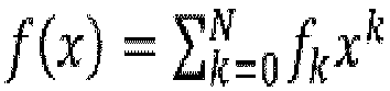
- a loss function is defined based on the difference between the polynomial defined by the output of the neural network and a polynomial representation of a real curve.
- the real curve here is a kind of ground truth data, which is the real ego driving path in this case.
- the coefficients of the ego path are obtained via a polynomial fitting to the real ego path.
- f k and g k being the polynomial coefficients
- x the distance from the ego-vehicle
- k the exponents of the polynomial
- L a distance of interest
- K(x) being a factor depending on x or constant
- N a grade of the polynomial.
- the loss function is defined by an integral over the squared differences of the real ego-path and the path predicted by the neural network, wherein the real ego-path and predicted path are represented as polynomials.
- the neural network is trained using a gradient descend algorithm based on this loss function.
- a learning rate decreasing schedule is applied.
- the driver-assistance system further comprises a camera, wherein the camera is configured to provide an image with the information about the objects to the processing unit.
- the camera captures an image of the environment of the ego-vehicle, including the road and objects in and along the road.
- the camera may also be a stereo camera to improve the detection and localization of objects.
- other sensors such as Radar, Lidar, ultrasonic sensors, etc. may provide additional information that may be used for calculating the probabilities.
- the camera may capture a series of images such that moving objects can be identified. For example, other vehicles driving along the road in the same direction shall not be bypassed. As another example, the movement of pedestrians may be predicted and taken into account when calculating the occupation probability.
- the series of images may be captured at short intervals and a single series may be used for one occupation probability calculation. The time distance between two such series may be, for example, the same time interval or a longer interval.
- moving objects may be identified by a series corresponding to the update rate of the path. That is, in this case, each image is used for an object recognition and a determination of the occupation probabilities. Moving objects may be identified by comparison with the previous image.
- the processing unit is further configured to divide the image by the grid into the grid cells and to determine for each grid cell the occupation probability.
- the grid may cover the complete image captured by the camera or only a part of it.
- the number of grid cells may be a fixed configured number.
- the number of grid cells may depend on the intended resolution.
- the processing unit comprises image processing routines or a further neural network to determine the occupation probabilities.
- Usual routines may be used to recognize and determine objects in an image. If a further neural network is used, this network may preferably be a convolutional neural network.
- a vehicle that comprises a driver-assistance system as described herein.
- a method for guiding a vehicle on a road comprises the following steps performed by a processing unit of a driver-assistance system.
- a processing unit of a driver-assistance system In a first step, information about objects on a road is received.
- the objects are mapped into a grid.
- a mathematical function is created from the grid, wherein the mathematical function represents a path for the vehicle on the road.
- the processing unit guides the vehicle along the path.
- the method may further comprise any other step or action described herein.
- the processing unit is defined such that it can perform all the steps mentioned above. Therefore, the processing unit may be a virtual logic in a connected system comprising one or several processors, wherein the one or several processors may be located in one or more different devices. For example, the driving control for guiding the vehicle may be physically separated from a unit that determines the path; nevertheless, these devices are defined as "processing unit" herein.
- a use of a deep neural network for guiding a vehicle on a road with obstacles is provided.
- the obstacles are objects on the road.
- the deep neural network is a convolutional neural network with an input layer populated with occupation probability values.
- the architecture of the deep neural network comprises several convolutional layers and several fully connected layers, and has an output layer that outputs coefficients of a polynomial that predicts the path along which the vehicle will be guided.
- the deep neural network is a neural network as descibed herein.
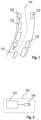
- Fig. 1 shows a diagram of a typical scenario, in which the invention is applied.
- a vehicle 110 here also referred to as "ego-vehicle” 110
- the dashed line 124 shows a suitable path along which a vehicle 110, here also referred to as "ego-vehicle" 110, may drive, with sufficient distance to the objects 120, 122.
- an image is taken of the environment by, for example, a camera mounted on the ego-vehicle 100. Further, a grid is laid over the image.
- the objects 120, 122 are detected and an occupation probability is determined for each cell of the grid.
- These probabilities for each grid cell are the input in the form of, for example, a matrix or, more generally, as a tensor for a deep convolutional neural network with an architecture as shown in Fig. 2 .
- Fig. 2 shows a block diagram of a driver-assistance system 100 with a processing unit 102 on which the neural network is implemented and a camera that provides the information from which the input for the neural network is calculated.
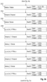
- Figs. 3a to 3c show an example of a deep convolutional neural network architecture 300 according to an embodiment.
- the architecture 300 comprises an input layer 302 with float32-values comprised in a matrix of size 40 x 61.
- the matrix corresponds to a grid applied to an image. For each cell of the grid, a probability of an area in the image, corresponding to an area on or near the road and that the area is occupied by an object has been determined.
- the float32-values of the input layer 302 represent these probabilities.
- the Input layer 302 is followed by a convolutional layer 304 to which 32 filters are applied such that the output are 32 feature maps, each of size 38x59. Each feature map is activated by a PReLu activation function 306.
- a max-pooling layer 308 halves the size of the feature maps. These steps are repeated for two further convolutional layers resulting in 32 feature maps of size 2x5.
- the feature maps are flattened to a vector of size 320.
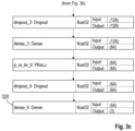
- the flattening layer is followed by a dropout 314 and a dense 316 layer, and further by a PReLU 318 activation function, whose output is the input for a next sequence of dropout and a dense layer. Note that for the dropout layer, the input dimension is the same as output dimension, since the dropout layer may be used only in the learning phase to avoid overfitting. In the predication phase after learning, the usage of the dropout layer may be omitted.
- the output size of the first dense layer is 512, which is halved in each sequence until the size is 64.
- the last dense layer 320 as shown in Fig. 3c , reduces the output to three.
- a linear activation function (not shown in Fig. 3c ) is applied to the output layer 320.
- the three output values are the coefficients of the polynomial representing the desired driving path. For all layers in the architecture, L1 regularization with a parameter of 0.01 is applied.
- the deep neural network 300 shown in Figs. 3a to 3c is trained using the gradient descend algorithm with a small learning rate of 1e -4 .
- FIG. 4 A typical result is shown in Fig. 4 .
- the solid line 404 is the real ego driving path while the dashed line 402 is the learned driving course using the designed deep neural network 300 shown in Figs. 3a to 3c .
- the black dots 406 in Fig. 4 represent occupied cells on the grid. Each dot had been assigned a probability value (not shown in Fig. 4 ) as input for the input layer 302 of the neural network 300. It can be seen that the learned driving course or learning path 402, respectively, is very close to the real ego driving path 404.
- Fig. 5 shows a block diagram of vehicle 110 that comprises a driver-assistance system 100.
- Fig. 6 shows a flow diagram of a method 600 for guiding a vehicle 110 on a road according to an embodiment.
- the method 600 comprises the following steps performed by a processing unit 102 of a driver-assistance system 100.
- a processing unit 102 of a driver-assistance system 100 receives information about objects on a road.
- the objects are mapped into a grid.
- a mathematical function is created from the grid, wherein the mathematical function represents a path for the vehicle on the road.
- the processing unit guides the vehicle along the path.
- the method may include further steps as described herein, especially with respect to the driver-assistance system.
- the presented aspects of the invention allow for predicting the driving course without manually designing cost functions.
- the model of the neural network can be updated as soon as new data is available. Due to the data-driven approach, the application cases and scenarios are not restricted, and no target positions are required.
Landscapes
- Engineering & Computer Science (AREA)
- Theoretical Computer Science (AREA)
- Physics & Mathematics (AREA)
- Data Mining & Analysis (AREA)
- General Health & Medical Sciences (AREA)
- Biomedical Technology (AREA)
- Biophysics (AREA)
- Computational Linguistics (AREA)
- Life Sciences & Earth Sciences (AREA)
- Evolutionary Computation (AREA)
- Artificial Intelligence (AREA)
- Molecular Biology (AREA)
- Computing Systems (AREA)
- General Engineering & Computer Science (AREA)
- General Physics & Mathematics (AREA)
- Mathematical Physics (AREA)
- Software Systems (AREA)
- Health & Medical Sciences (AREA)
- Traffic Control Systems (AREA)
Abstract
Description
- The invention relates to a driver-assistance system, a vehicle, a method for guiding a vehicle on a road and a use of a deep neural network for guiding a vehicle on a road with obstacles.
- Driver-assistance systems require a comprehensive understanding of the environment surrounding the vehicle. For example, common driving functions like forward collision avoidance system and emergency brake assist demand a precise prediction of the path the vehicle will follow in the next cycles. However, static and dynamic objects such as driving or parking vehicles, trees and bushes, walls, buildings, and other physical barriers may influence and restrict this path. Usual calculation of trajectories and path planning methods rely on known targets positions. In practical driving, objects in the surrounding are detected; however, such detections do not provide target position a vehicle shall drive to.
- Therefore, one object of the invention may be to provide an improved driver-assistance system.
- The problem is solved by the subject-matter of the independent claims. Embodiments are provided by the dependent claims, the following description and the accompanying figures.
- The described embodiments similarly pertain to the driver-assistance system, the vehicle, the method for guiding a vehicle on a road and the use of a deep neural network for guiding a vehicle on a road with obstacles. Synergetic effects may arise from different combinations of the embodiments although they might not be described in detail.
- Further on, it shall be noted that all embodiments of the present invention concerning a method might be carried out with the order of the steps as described, nevertheless this has not to be the only and essential order of the steps of the method. The herein presented methods can be carried out with another order of the disclosed steps without departing from the respective method embodiment, unless explicitly mentioned to the contrary hereinafter.
- According to a first aspect, a driver-assistance system for a vehicle is provided. The driver-assistance system comprises a processing unit configured to receive information about objects on a road, map the objects into a grid, create a mathematical function based on the grid, wherein the mathematical function represents a path for the vehicle on the road, and to guide the vehicle along the path.
- In other words, a grid is created that is populated with information about the objects on the road is created. The grid may be based on an image such that the entries of the grid correspond to detected objects on the image. The processing unit uses the grid as input and provides a mathematical function as output, where the mathematical function represents the path. Thereby, the mathematical function is not a trajectory or a series of trajectories each comprising a starting position and a target position. Instead, the mathematical function represents a continuous path, which is fitted such that the objects are circumnavigated or bypassed in an optimal way. The mathematical function is updated, for example, in regular intervals.
- According to an embodiment, the processing unit comprises a neural network, wherein the input of the neural network is the grid and the output of the neural network is a representation of the mathematical function.
- Technically, the driving course prediction may be formulated as a regression issue in the context of deep machine learning, which learns a mapping function from the input data to the out vector. The deep machine learning may be a neural network that only requires the grid as input such that no target position has to be determined for calculating a trajectory. Determining target positions may be laborious and inexact. In conventional systems, the type of object is not discriminated and several target positions and stepwise trajectories have to be calculated in order to provide a sufficiently long prevision. By using a neural network as described herein, the output is a mathematical function without steps defined by target positions. The driver-assistance system can use the mathematical function for guiding the vehicle and for preparing actions without limitation regarding the length of the predicted path. Further, the described neural network, can take the different behavior of static and dynamic objects can into account.
- According to an embodiment, the grid is composed as a numerical tensor, in which each cell corresponds to an area of the road and comprises a numerical number corresponding to an occupation probability of the area.
- The grid is mathematically spoken a tensor, where each grid cell is identified by its position in two dimensions of the tensor. The grid corresponds to a grid laid over an image containing the static and dynamic objects in the environment of the vehicle. That is, each grid cell corresponds to an area on the image. In a simple case, the tensor is a two-dimensional vector, i.e., a matrix. The values of the matrix are the occupation probability, i.e. the probability, that an object occupies the corresponding area on the image. More generalized, the more-dimensional tensor may contain further information for each cell such as original values of the image, for example, color values or grey scale values.
- The probability values may be obtained by preprocessing the image. In a simple case, as an illustrative example, the probability values correspond to grey scale values or similar and may be one when exceeding a threshold or zero otherwise. However, a much more complex mapping of the content of the image to probabilities may be applied.
- According to an embodiment, the mathematical function is a polynomial.
- The polynomial does not need to have support points, as it might be the case for trajectories with target positions. Especially, when using a neural network, the network determines the polynomial, and there are no target positions to be met.
- According to an embodiment, the mathematical function is represented by a vector containing coefficients of the polynomial, and the output of the neural network is the vector containing the coefficients. The mathematical function may be, however, any suitable type of function that defines a curve with coefficients or parameters.
- The actual output of the neural network may be a vector containing coefficients of the polynomial. The coefficients represent the mathematical function.
- According to an embodiment, the neural network is a deep neural network comprising several convolutional layers, wherein each convolutional layer is followed by a max-pooling layer.
- The number of convolutional layers may be two, preferably three, or more layers. The max-pooling layers after each convolutional layer reduce the dimension of the system. The convolutional layers may be followed by a flattening layer and one or several fully connected layers. A non-linear activation may be applied for each convolutional layer. A non-linear activation may be also be applied for the flattening layer and the following fully connected layers. Preferably, the non-linear activation is a parametric rectifying Linear Unit (PReLU), where the neurons may learn the parameter α for obtaining the best slope in the negative region, that is, the gradient α for values of linear sum z = w1 x1 + w2 x2 + ... + wn xn + b < 0, where wi are the weights and x the output values of the filter applied to the convolutional layer. However, also any other activation functions may be used, such as sigmoid, thanh, maxout, Exponential Linear Unit (ELU), softmax, etc.
- In order to reduce overfitting, dropout layers may follow the flattening layer and each of the fully connected layers. The drop probability may be, for example, 0.5.
- Furthermore, an L1 regularization may be applied for all layers. Preferably, for the reduction of the weights, a factor of 0.01 is applied.
- According to an embodiment, the output layer comprises a linear activation function. The linear activation function takes into account that a regression problem has to be resolved, where the output are the real values of polynomial coefficients. Alternatively, a particular processing may be applied when using other types of activation functions.
- According to an embodiment, a loss function is defined based on the difference between the polynomial defined by the output of the neural network and a polynomial representation of a real curve.
- The real curve here is a kind of ground truth data, which is the real ego driving path in this case. As the real ego path is known, the coefficients of the ego path are obtained via a polynomial fitting to the real ego path.
- According to an embodiment, the loss function is given as


- In words, the loss function is defined by an integral over the squared differences of the real ego-path and the path predicted by the neural network, wherein the real ego-path and predicted path are represented as polynomials.
- The neural network is trained using a gradient descend algorithm based on this loss function. In order to improve the convergence when training a deep neural network model, a learning rate decreasing schedule is applied.
- According to an embodiment, the driver-assistance system further comprises a camera, wherein the camera is configured to provide an image with the information about the objects to the processing unit.
- The camera captures an image of the environment of the ego-vehicle, including the road and objects in and along the road. The camera may also be a stereo camera to improve the detection and localization of objects. In addition, other sensors such as Radar, Lidar, ultrasonic sensors, etc. may provide additional information that may be used for calculating the probabilities.
- Further, the camera may capture a series of images such that moving objects can be identified. For example, other vehicles driving along the road in the same direction shall not be bypassed. As another example, the movement of pedestrians may be predicted and taken into account when calculating the occupation probability. The series of images may be captured at short intervals and a single series may be used for one occupation probability calculation. The time distance between two such series may be, for example, the same time interval or a longer interval. Alternatively, moving objects may be identified by a series corresponding to the update rate of the path. That is, in this case, each image is used for an object recognition and a determination of the occupation probabilities. Moving objects may be identified by comparison with the previous image.
- According to an embodiment, the processing unit is further configured to divide the image by the grid into the grid cells and to determine for each grid cell the occupation probability.
- The grid may cover the complete image captured by the camera or only a part of it. The number of grid cells may be a fixed configured number. The number of grid cells may depend on the intended resolution.
- According to an embodiment, the processing unit comprises image processing routines or a further neural network to determine the occupation probabilities.
- Usual routines may be used to recognize and determine objects in an image. If a further neural network is used, this network may preferably be a convolutional neural network.
- According to a further aspect, a vehicle is provided that comprises a driver-assistance system as described herein.
- According to a further aspect, a method for guiding a vehicle on a road is provided. The method comprises the following steps performed by a processing unit of a driver-assistance system. In a first step, information about objects on a road is received. In a second step, the objects are mapped into a grid. In a third step, a mathematical function is created from the grid, wherein the mathematical function represents a path for the vehicle on the road. In a fourth step, the processing unit guides the vehicle along the path.
- The method may further comprise any other step or action described herein. The processing unit is defined such that it can perform all the steps mentioned above. Therefore, the processing unit may be a virtual logic in a connected system comprising one or several processors, wherein the one or several processors may be located in one or more different devices. For example, the driving control for guiding the vehicle may be physically separated from a unit that determines the path; nevertheless, these devices are defined as "processing unit" herein.
- According to a further aspect, a use of a deep neural network for guiding a vehicle on a road with obstacles.
- The obstacles are objects on the road.
- The deep neural network is a convolutional neural network with an input layer populated with occupation probability values. The architecture of the deep neural network comprises several convolutional layers and several fully connected layers, and has an output layer that outputs coefficients of a polynomial that predicts the path along which the vehicle will be guided. The deep neural network is a neural network as descibed herein.
- These and other features, aspects and advantages of the present invention will become better understood with reference to the accompanying figures and the following description.
-
-
Fig. 1 shows a diagram of a typical scenario. -
Fig. 2 shows a diagram of a driver-assistance system. -
Figs. 3a to 3c show a diagram with an example of a deep neural network according to an embodiment. -
Fig. 4 shows a diagram of occupied cells and predicted path using real data. -
Fig. 5 shows a block diagram of vehicle with a driver-assistance system. -
Fig. 6 shows a flow diagram of a method according to an embodiment. - Corresponding parts are provided with the same reference symbols in all figures.
-
Fig. 1 shows a diagram of a typical scenario, in which the invention is applied. On the road shown inFig. 1 , there aretrees 120 andparking cars 122 on the left side andparking cars 122 on the right side. The dashedline 124 shows a suitable path along which avehicle 110, here also referred to as "ego-vehicle" 110, may drive, with sufficient distance to theobjects path 124, an image is taken of the environment by, for example, a camera mounted on the ego-vehicle 100. Further, a grid is laid over the image. Theobjects Fig. 2 . -
Fig. 2 shows a block diagram of a driver-assistance system 100 with aprocessing unit 102 on which the neural network is implemented and a camera that provides the information from which the input for the neural network is calculated. -
Figs. 3a to 3c show an example of a deep convolutionalneural network architecture 300 according to an embodiment. Thearchitecture 300 comprises aninput layer 302 with float32-values comprised in a matrix of size 40 x 61. The matrix corresponds to a grid applied to an image. For each cell of the grid, a probability of an area in the image, corresponding to an area on or near the road and that the area is occupied by an object has been determined. The float32-values of theinput layer 302 represent these probabilities. TheInput layer 302 is followed by aconvolutional layer 304 to which 32 filters are applied such that the output are 32 feature maps, each of size 38x59. Each feature map is activated by aPReLu activation function 306. A max-pooling layer 308 halves the size of the feature maps. These steps are repeated for two further convolutional layers resulting in 32 feature maps of size 2x5. In anext step 312, as shown inFig. 3b , the feature maps are flattened to a vector ofsize 320. The flattening layer is followed by adropout 314 and a dense 316 layer, and further by aPReLU 318 activation function, whose output is the input for a next sequence of dropout and a dense layer. Note that for the dropout layer, the input dimension is the same as output dimension, since the dropout layer may be used only in the learning phase to avoid overfitting. In the predication phase after learning, the usage of the dropout layer may be omitted. The output size of the first dense layer is 512, which is halved in each sequence until the size is 64. The lastdense layer 320, as shown inFig. 3c , reduces the output to three. Finally, a linear activation function (not shown inFig. 3c ) is applied to theoutput layer 320. The three output values are the coefficients of the polynomial representing the desired driving path. For all layers in the architecture, L1 regularization with a parameter of 0.01 is applied. - In the learning phase, a loss function is defined based on the difference between the real curve expressed as a polynomial


- Applying the substitutions h(x) = f(x) - g(x) on the left side, and hk = fk - gk on the right side results in:

- Then, the loss function can be written as


- Based on this loss function, the deep
neural network 300 shown inFigs. 3a to 3c is trained using the gradient descend algorithm with a small learning rate of 1e-4. - A typical result is shown in
Fig. 4 . Thesolid line 404 is the real ego driving path while the dashedline 402 is the learned driving course using the designed deepneural network 300 shown inFigs. 3a to 3c . Theblack dots 406 inFig. 4 represent occupied cells on the grid. Each dot had been assigned a probability value (not shown inFig. 4 ) as input for theinput layer 302 of theneural network 300. It can be seen that the learned driving course or learningpath 402, respectively, is very close to the realego driving path 404. -
Fig. 5 shows a block diagram ofvehicle 110 that comprises a driver-assistance system 100. -
Fig. 6 shows a flow diagram of amethod 600 for guiding avehicle 110 on a road according to an embodiment. Themethod 600 comprises the following steps performed by aprocessing unit 102 of a driver-assistance system 100. In afirst step 602, information about objects on a road is received. In asecond step 604, the objects are mapped into a grid. In athird step 606, a mathematical function is created from the grid, wherein the mathematical function represents a path for the vehicle on the road. In afourth step 608, the processing unit guides the vehicle along the path. - The method may include further steps as described herein, especially with respect to the driver-assistance system.
- The presented aspects of the invention allow for predicting the driving course without manually designing cost functions. The model of the neural network can be updated as soon as new data is available. Due to the data-driven approach, the application cases and scenarios are not restricted, and no target positions are required.
- Other variations to the disclosed embodiments can be understood and effected by those skilled in the art in practicing the claimed invention, from the study of the drawings, the disclosure, and the appended claims. In the claims, the word "comprising" does not exclude other elements or steps and the indefinite article "a" or "an" does not exclude a plurality. A single processor or other unit may fulfill the functions of several items or steps recited in the claims. The mere fact that certain measures are recited in mutually different dependent claims does not indicate that a combination of these measures cannot be used to advantage. Any reference signs in the claims should not be construed as limiting the scope of the claims.
-
- 100
- driver-assistance system
- 102
- processing unit
- 104
- camera
- 110
- ego-vehicle
- 120
- objects on the road: trees
- 122
- objects on the road: parking vehicles
- 124
- predicted path
- 300
- neural network (architecture)
- 302
- input layer of the neural network
- 304
- convolutional layer of the neural network
- 306
- PReLu function of the neural network
- 308
- max-pooling layer of the neural network
- 312
- flattening layer of the neural network
- 314
- dropout layer of the neural network
- 316
- dense layer (fully connected layer) of the neural network
- 306
- PReLu function of the neural network
- 320
- output layer of the neural network
- 402
- predicted path
- 404
- real path
- 406
- occupied cells
- 600
- method
- 602
- first step of the method
- 604
- second step of the method
- 606
- third step of the method
- 608
- fourth step of the method
Claims (15)
- Driver-assistance system (100) for a vehicle (110) comprising a
Processing unit (102) configured toreceive information about objects on a road;map the objects (120, 122) into a grid;create a mathematical function based on the grid, wherein the mathematical function represents a path (402) for the vehicle (110) on the road;guide the vehicle (110) along the path (402). - Driver-assistance system (100) according to claim 1, wherein the processing unit (102) comprises a neural network (300), wherein the input of the neural network (300) is the grid and the output of the neural network (300) is a representation of the mathematical function.
- Driver-assistance system (100) according to claim 1 or 2, wherein the grid is composed as a numerical tensor, in which each grid cell corresponds to an area of the road and comprises a numerical number corresponding to an occupation probability of the area.
- Driver-assistance system (100) according to any one of the previous claims, wherein the mathematical function is a polynomial.
- Driver-assistance system (100) according to claim 4, wherein the mathematical function is represented by a vector containing coefficients of the polynomial, and the output of the neural network (300) is the vector containing the coefficients.
- Driver-assistance system (100) according to claim 5, wherein neural network (300) is a deep neural network (300) comprising several convolutional layers, wherein each convolutional layer is followed by a max-pooling layer.
- Driver-assistance system (100) according to any one of claims 2 to 6, wherein an output layer (320) comprises a linear activation function.
- Driver-assistance system (100) according to anyone of claims 4 to 7, wherein a loss function is defined based on the difference between the polynomial defined by the output of the neural network (300) and a polynomial representation of the real curve.
- Driver-assistance system (100) according to claim 8, wherein the loss function is given as


- Driver-assistance system (100) according to claim 1, further comprising a camera (104), wherein the camera (104) is configured to provide an image with the information about the objects to the processing unit.
- Driver-assistance system (100) according to any one of claims 3 to 10, wherein the processing unit is further configured to divide the image by the grid into the grid cells and to determine for each grid cell the occupation probability.
- Driver-assistance system (100) according to claim 11, wherein the processing unit comprises image processing routines or a further neural network (300) to determine the occupation probabilities.
- Vehicle (110) comprising a driver-assistance system according to any one of the preceding claims.
- Method (600) for guiding a vehicle (110) on a road comprising the steps performed by a processing unit of a driver-assistance system (100):receiving (602) information about objects on a road;mapping (604) the objects into a grid;creating (606) a mathematical function from the grid, wherein the mathematical function represents a path (402) for the vehicle (110) on the road;guiding (608) the vehicle (110) along the path (402).
- Use of a deep neural network (300) for guiding a vehicle (110) on a road with obstacles (120, 122).
Priority Applications (1)
| Application Number | Priority Date | Filing Date | Title |
|---|---|---|---|
| EP22163330.8A EP4250183A1 (en) | 2022-03-21 | 2022-03-21 | Driver-assistance system with neural network |
Applications Claiming Priority (1)
| Application Number | Priority Date | Filing Date | Title |
|---|---|---|---|
| EP22163330.8A EP4250183A1 (en) | 2022-03-21 | 2022-03-21 | Driver-assistance system with neural network |
Publications (1)
| Publication Number | Publication Date |
|---|---|
| EP4250183A1 true EP4250183A1 (en) | 2023-09-27 |
Family
ID=80928834
Family Applications (1)
| Application Number | Title | Priority Date | Filing Date |
|---|---|---|---|
| EP22163330.8A Pending EP4250183A1 (en) | 2022-03-21 | 2022-03-21 | Driver-assistance system with neural network |
Country Status (1)
| Country | Link |
|---|---|
| EP (1) | EP4250183A1 (en) |
Citations (1)
| Publication number | Priority date | Publication date | Assignee | Title |
|---|---|---|---|---|
| US20190176818A1 (en) * | 2017-12-11 | 2019-06-13 | Volvo Car Corporation | Path prediction for a vehicle |
-
2022
- 2022-03-21 EP EP22163330.8A patent/EP4250183A1/en active Pending
Patent Citations (1)
| Publication number | Priority date | Publication date | Assignee | Title |
|---|---|---|---|---|
| US20190176818A1 (en) * | 2017-12-11 | 2019-06-13 | Volvo Car Corporation | Path prediction for a vehicle |
Non-Patent Citations (3)
| Title |
|---|
| SCHOMER PHILIP ET AL: "Optimization of Sampling-Based Motion Planning in Dynamic Environments Using Neural Networks", 2020 IEEE INTELLIGENT VEHICLES SYMPOSIUM (IV) IEEE, 19 October 2020 (2020-10-19), pages 2110 - 2117, XP033873206, [retrieved on 20201222], DOI: 10.1109/IV47402.2020.9304644 * |
| T. BUHET ET AL.: "Conditional Vehicle Trajectories Prediction in CARLA Urban Environment", 2019 IEEE/CVF INTERNATIONAL CONFERENCE ON COMPUTER VISION WORKSHOP (ICCVW), 27 October 2019 (2019-10-27), pages 2310 - 2319, XP033732609, DOI: 10.1109/ICCVW.2019.00284 * |
| Z. SU ET AL.: "Temporally-Continuous Probabilistic Prediction using Polynomial Trajectory Parameterization", 2021 IEEE/RSJ INTERNATIONAL CONFERENCE ON INTELLIGENT ROBOTS AND SYSTEMS (IROS), 27 September 2021 (2021-09-27), pages 3837 - 3843, XP034051445, DOI: 10.1109/IROS51168.2021.9636751 * |
Similar Documents
| Publication | Publication Date | Title |
|---|---|---|
| EP4137845B1 (en) | Methods and systems for predicting properties of a plurality of objects in a vicinity of a vehicle | |
| US11465633B2 (en) | Method and system for generating predicted occupancy grid maps | |
| US11827214B2 (en) | Machine-learning based system for path and/or motion planning and method of training the same | |
| CN116348938B (en) | Method and system for predicting the behavior of dynamic objects | |
| EP3822852B1 (en) | Method, apparatus, computer storage medium and program for training a trajectory planning model | |
| US20190287404A1 (en) | Traffic prediction with reparameterized pushforward policy for autonomous vehicles | |
| EP3278317B1 (en) | Method and electronic device | |
| US11364899B2 (en) | Driving assistance method and system | |
| CN111736142A (en) | System and method for radar cross-traffic tracking and maneuvering risk assessment | |
| US11693415B2 (en) | Predicting cut-in probabilities of surrounding agents | |
| Deng et al. | Prediction of human driver behaviors based on an improved HMM approach | |
| CN110843789A (en) | Vehicle lane change intention prediction method based on time sequence convolution network | |
| US11804034B2 (en) | Training a function to respond predictably to differences | |
| JP2024521717A (en) | Safe control and monitoring of computer-controlled systems | |
| Hegde et al. | Vehicle trajectory prediction using gan | |
| KR102236792B1 (en) | Method and system for learning lane changeable time based on camera and method and system for predicting time lane changeable time | |
| Althoff et al. | Safety assessment of driving behavior in multi-lane traffic for autonomous vehicles | |
| EP4276773A1 (en) | Deep association for sensor fusion | |
| Kumar et al. | A deep transfer learning approach for enhanced traffic sign recognition in autonomous vehicles with nvidia jetson nano | |
| Masmoudi et al. | Autonomous car-following approach based on real-time video frames processing | |
| CN119796253B (en) | A method, system, and autonomous vehicle for lane-changing decision-making. | |
| EP4219259B1 (en) | Method, computer system and non-transitory computer readable medium for target selection in the vicinity of a vehicle | |
| Zhang et al. | A convolutional neural network method for self-driving cars | |
| CN121425251A (en) | Methods, devices, electronic equipment, media and products for risk assessment of autonomous vehicles | |
| JP7560040B2 (en) | Semantic Segmentation Using Targeted Global Dissimilarity Loss |
Legal Events
| Date | Code | Title | Description |
|---|---|---|---|
| PUAI | Public reference made under article 153(3) epc to a published international application that has entered the european phase |
Free format text: ORIGINAL CODE: 0009012 |
|
| STAA | Information on the status of an ep patent application or granted ep patent |
Free format text: STATUS: THE APPLICATION HAS BEEN PUBLISHED |
|
| AK | Designated contracting states |
Kind code of ref document: A1 Designated state(s): AL AT BE BG CH CY CZ DE DK EE ES FI FR GB GR HR HU IE IS IT LI LT LU LV MC MK MT NL NO PL PT RO RS SE SI SK SM TR |
|
| STAA | Information on the status of an ep patent application or granted ep patent |
Free format text: STATUS: REQUEST FOR EXAMINATION WAS MADE |
|
| 17P | Request for examination filed |
Effective date: 20240327 |
|
| RBV | Designated contracting states (corrected) |
Designated state(s): AL AT BE BG CH CY CZ DE DK EE ES FI FR GB GR HR HU IE IS IT LI LT LU LV MC MK MT NL NO PL PT RO RS SE SI SK SM TR |
|
| RAP3 | Party data changed (applicant data changed or rights of an application transferred) |
Owner name: AUMOVIO AUTONOMOUS MOBILITY GERMANY GMBH |
|
| STAA | Information on the status of an ep patent application or granted ep patent |
Free format text: STATUS: EXAMINATION IS IN PROGRESS |
|
| 17Q | First examination report despatched |
Effective date: 20260622 |