EP4250156A1 - System and method for providing security to legacy devices - Google Patents
System and method for providing security to legacy devices Download PDFInfo
- Publication number
- EP4250156A1 EP4250156A1 EP23160291.3A EP23160291A EP4250156A1 EP 4250156 A1 EP4250156 A1 EP 4250156A1 EP 23160291 A EP23160291 A EP 23160291A EP 4250156 A1 EP4250156 A1 EP 4250156A1
- Authority
- EP
- European Patent Office
- Prior art keywords
- controller
- legacy device
- code
- legacy
- controllers
- Prior art date
- Legal status (The legal status is an assumption and is not a legal conclusion. Google has not performed a legal analysis and makes no representation as to the accuracy of the status listed.)
- Pending
Links
Images



Classifications
-
- G—PHYSICS
- G06—COMPUTING OR CALCULATING; COUNTING
- G06F—ELECTRIC DIGITAL DATA PROCESSING
- G06F21/00—Security arrangements for protecting computers, components thereof, programs or data against unauthorised activity
- G06F21/30—Authentication, i.e. establishing the identity or authorisation of security principals
- G06F21/44—Program or device authentication
-
- G—PHYSICS
- G06—COMPUTING OR CALCULATING; COUNTING
- G06F—ELECTRIC DIGITAL DATA PROCESSING
- G06F21/00—Security arrangements for protecting computers, components thereof, programs or data against unauthorised activity
- G06F21/60—Protecting data
- G06F21/62—Protecting access to data via a platform, e.g. using keys or access control rules
- G06F21/629—Protecting access to data via a platform, e.g. using keys or access control rules to features or functions of an application
-
- G—PHYSICS
- G05—CONTROLLING; REGULATING
- G05B—CONTROL OR REGULATING SYSTEMS IN GENERAL; FUNCTIONAL ELEMENTS OF SUCH SYSTEMS; MONITORING OR TESTING ARRANGEMENTS FOR SUCH SYSTEMS OR ELEMENTS
- G05B19/00—Program-control systems
- G05B19/02—Program-control systems electric
- G05B19/04—Program control other than numerical control, i.e. in sequence controllers or logic controllers
- G05B19/042—Program control other than numerical control, i.e. in sequence controllers or logic controllers using digital processors
- G05B19/0428—Safety, monitoring
-
- G—PHYSICS
- G06—COMPUTING OR CALCULATING; COUNTING
- G06F—ELECTRIC DIGITAL DATA PROCESSING
- G06F21/00—Security arrangements for protecting computers, components thereof, programs or data against unauthorised activity
- G06F21/50—Monitoring users, programs or devices to maintain the integrity of platforms, e.g. of processors, firmware or operating systems
- G06F21/57—Certifying or maintaining trusted computer platforms, e.g. secure boots or power-downs, version controls, system software checks, secure updates or assessing vulnerabilities
- G06F21/572—Secure firmware programming, e.g. of basic input output system [BIOS]
-
- G—PHYSICS
- G06—COMPUTING OR CALCULATING; COUNTING
- G06F—ELECTRIC DIGITAL DATA PROCESSING
- G06F8/00—Arrangements for software engineering
- G06F8/60—Software deployment
-
- G—PHYSICS
- G06—COMPUTING OR CALCULATING; COUNTING
- G06F—ELECTRIC DIGITAL DATA PROCESSING
- G06F2221/00—Indexing scheme relating to security arrangements for protecting computers, components thereof, programs or data against unauthorised activity
- G06F2221/03—Indexing scheme relating to G06F21/50, monitoring users, programs or devices to maintain the integrity of platforms
- G06F2221/034—Test or assess a computer or a system
Definitions
- This disclosure is generally directed to industrial control and automation systems. More specifically, this disclosure relates to a system and method for securing and preventing changes to the configuration and firmware of legacy devices of an industrial process control and automation system.
- Legacy process and safety controllers, gateways, and IO modules used in industrial process control and automation systems have been deployed with older hardware technology that do not have the latest cyber security protections such as for example secure boot, signed firmware, and download verification. These legacy devices and the system platforms supporting these devise also may not have the processing power to provide secure, encrypted, and authenticated communications.
- the legacy devices rely heavily on layered system security of the automation system. However, if these system protections are defeated, then it is possible for a bad actor to gain access to an engineering workstation or to a process control network to shutdown the legacy devices or worse permanently disable them by loading counterfeit firmware that could cause loss of control, bad control, or even damage to a device to the point where it cannot be recovered.
- This disclosure relates to a system and method for securing and preventing changes to the configuration and firmware of legacy devices of an industrial process control and automation system.
- a method comprising setting a lock code in a device index of the legacy device.
- the method further including executing a monitoring program that reads the lock code and sets the legacy device in a locked state and executing an enforcement program that prevents changes to the configuration and firmware of the legacy device when the legacy device is in the locked state.
- the first embodiment further includes a method for releasing the legacy device from the lock state comprising, setting an unlock code in the device index of the legacy device and executing the monitoring program to read the unlock code and set the legacy device in an unlocked state.
- the enforcement program allowing changes to the configuration and firmware of the legacy device when the legacy device is in the unlocked state.
- a system comprising a device index associated with a legacy device.
- the device index is manipulable to enter a lock code and processing circuitry is configured to read the lock code and set the legacy device in a locked state.
- the device index is further manipulable to enter an unlock code and the processing circuitry is configured to read the unlock code and set the legacy device in an unlocked state.
- This disclosure has the benefit of providing a way to lock down devices used in an industrial process control and automation system such as for example, a controller, a wireless gateway, or an I/O module from any changes to its configuration and firmware. This will prevent a rip and replace of a controller or other device used in the industrial process control and automation system from using counterfeit firmware or from a cyber security attack.
- This disclosure allows legacy process and safety controllers, gateways, and I/O modules to be protected from cyber security attacks with only a software update to the devices.
- FIG. 1 illustrates an example industrial process control and automation system 100 according to this disclosure.
- the system 100 includes various components that facilitate production or processing of at least one product or other material.
- the system 100 is used here to facilitate control over components in one or multiple plants 101a-101n.
- Each plant 101a-101n represents one or more processing facilities (or one or more portions thereof), such as one or more manufacturing facilities for producing at least one product or other material.
- each plant 101a-101n may implement one or more processes and can individually or collectively be referred to as a process system.
- a process system generally represents any system or portion thereof configured to process one or more products or other materials in some manner.
- Level 0 may include one or more sensors 102a and one or more actuators 102b.
- the sensors 102a and actuators 102b represent components in a process system that may perform any of a wide variety of functions.
- the sensors 102a could measure a wide variety of characteristics in the process system, such as temperature, pressure, or flow rate.
- the actuators 102b could alter a wide variety of characteristics in the process system.
- the sensors 102a and actuators 102b could represent any other or additional components in any suitable process system.
- Each of the sensors 102a includes any suitable structure for measuring one or more characteristics in a process system.
- Each of the actuators 102b includes any suitable structure for operating on or affecting one or more conditions in a process system.
- Each of the sensors 102a and actuators 102b are connected to at least one network 104 through a respective 1/O module 105a, 105b.
- the I/O modules providing proper interface connections, such as copper cabling or fiber optic cabling or communication and signal protocols for the type of sensor or actuator used.
- the network 104 facilitates interaction with the I/O modules 105a, 105b and sensors 102a and actuators 102b.
- the network 104 could transport measurement data from the I/O modules 105a, 105b and sensors 102a and provide control signals to the actuators 102b through I/O module 105a and 105b.
- the network 104 could represent any suitable network or combination of networks.
- the network 104 could represent an Ethernet network, an electrical signal network (such as a HART or FOUNDATION FIELDBUS network), a pneumatic control signal network, or any other or additional type(s) of network(s).
- Level 1 may include one or more controllers 106, which are coupled to the network 104.
- each controller 106 may use the measurements from one or more sensors 102a to control the operation of one or more actuators 102b.
- a controller 106 could receive measurement data from one or more I/O modules 105a and 105b and its associated connected sensors 102a and use the measurement data to generate control signals for one or more actuators 102b.
- Each controller 106 includes any suitable structure for interacting with one or more I/O modules 105a and 105b to control the one or more actuators 102b.
- Each controller 106 could, for example, represent a proportional-integral-derivative (PID) controller or a multivariable controller, such as a Robust Multivariable Predictive Control Technology (RMPCT) controller or other type of controller implementing model predictive control (MPC) or other advanced predictive control (APC).
- PID proportional-integral-derivative
- RPCT Robust Multivariable Predictive Control Technology
- MPC model predictive control
- API advanced predictive control
- each controller 106 could represent a computing device running a real-time operating system.
- the networks 108 are coupled to the controllers 106.
- the networks 108 facilitate interaction with the controllers 106, such as by transporting data to and from the controllers 106.
- the networks 108 could represent any suitable networks or combination of networks.
- the networks 108 could represent a redundant pair of Ethernet networks, such as a FALTLT TOLERANT ETHERNET (FTE) network from HONEYWELL INTERNATIONAL INC.
- FTE FALTLT TOLERANT ETHERNET
- At least one switch/firewall 110 couples the networks 108 to two networks 112.
- the switch/firewall 110 may transport traffic from one network to another.
- the switch/firewall 110 may also block traffic on one network from reaching another network.
- the switch/firewall 110 includes any suitable structure for providing communication between networks, such as a HONEYWELL CONTROL FIREWALL (CF9) device.
- the networks 112 could represent any suitable networks, such as an FTE network.
- Level 2 may include one or more machine-level controllers 114 coupled to the networks 112.
- the machine-level controllers 114 perform various functions to support the operation and control of the controllers 106, I/O modules 105a and 105b, sensors 102a, and actuators 102b, which could be associated with a particular piece of industrial equipment (such as a boiler or other machine).
- the machine-level controllers 114 could log information collected or generated by the controllers 106, such as measurement data from the sensors 102a or control signals for the actuators 102b.
- the machine-level controllers 114 could also execute applications that control the operation of the controllers 106, thereby controlling the operation of the actuators 102b.
- the machine-level controllers 114 could provide secure access to the controllers 106.
- Each of the machine-level controllers 114 includes any suitable structure for providing access to, control of, or operations related to a machine or other individual piece of equipment.
- Each of the machine-level controllers 114 could, for example, represent a server computing device running a MICROSOFT WINDOWS operating system.
- different machine-level controllers 114 could be used to control different pieces of equipment in a process system (where each piece of equipment is associated with one or more controllers 106, sensors 102a, and actuators 102b).
- One or more operator stations 116 are coupled to the networks 112.
- the operator stations 116 represent computing or communication devices providing user access to the machine-level controllers 114, which could then provide user access to the controllers 106 (and possibly the sensors 102a and actuators 102b).
- the operator stations 116 could allow users to review the operational history of the sensors 102a and actuators 102b using information collected by the controllers 106 and/or the machine-level controllers 114.
- the operator stations 116 could also allow the users to adjust the operation of the sensors 102a, actuators 102b, controllers 106, or machine-level controllers 114.
- the operator stations 116 could receive and display warnings, alerts, or other messages or displays generated by the controllers 106 or the machine-level controllers 114.
- Each of the operator stations 116 includes any suitable structure for supporting user access and control of one or more components in the system 100.
- Each of the operator stations 116 could, for example, represent a computing device running a MICROSOFT WINDOWS operating system.
- At least one router/firewall 118 couples the networks 112 to two networks 120.
- the router/firewall 118 includes any suitable structure for providing communication between networks, such as a secure router or combination router/firewall.
- the networks 120 could represent any suitable networks, such as an FTE network.
- Level 3 may include one or more unit-level controllers 122 coupled to the networks 120.
- Each unit-level controller 122 is typically associated with a unit in a process system, which represents a collection of different machines operating together to implement at least part of a process.
- the unit-level controllers 122 perform various functions to support the operation and control of components in the lower levels.
- the unit-level controllers 122 could log information collected or generated by the components in the lower levels, execute applications that control the components in the lower levels, and provide secure access to the components in the lower levels.
- Each of the unit-level controllers 122 includes any suitable structure for providing access to, control of, or operations related to one or more machines or other pieces of equipment in a process unit.
- Each of the unit-level controllers 122 could, for example, represent a server computing device running a MICROSOFT WINDOWS operating system. Although not shown, different unit-level controllers 122 could be used to control different units in a process system (where each unit is associated with one or more machine-level controllers 114, controllers 106, sensors 102a, and actuators 102b).
- Access to the unit-level controllers 122 may be provided by one or more operator stations 124.
- Each of the operator stations 124 includes any suitable structure for supporting user access and control of one or more components in the system 100.
- Each of the operator stations 124 could, for example, represent a computing device running a MICROSOFT WINDOWS operating system.
- At least one router/firewall 126 couples the networks 120 to two networks 128.
- the router/firewall 126 includes any suitable structure for providing communication between networks, such as a secure router or combination router/firewall.
- the networks 128 could represent any suitable networks, such as an FTE network.
- Level 4" may include one or more plant-level controllers 130 coupled to the networks 128.
- Each plant-level controller 130 is typically associated with one of the plants 101a-101n, which may include one or more process units that implement the same, similar, or different processes.
- the plant-level controllers 130 perform various functions to support the operation and control of components in the lower levels.
- the plant-level controller 130 could execute one or more manufacturing execution system (MES) applications, scheduling applications, or other or additional plant or process control applications.
- MES manufacturing execution system
- Each of the plant-level controllers 130 includes any suitable structure for providing access to, control of, or operations related to one or more process units in a process plant.
- Each of the plant-level controllers 130 could, for example, represent a server computing device running a MICROSOFT WINDOWS operating system.
- Access to the plant-level controllers 130 may be provided by one or more operator stations 132.
- Each of the operator stations 132 includes any suitable structure for supporting user access and control of one or more components in the system 100.
- Each of the operator stations 132 could, for example, represent a computing device running a MICROSOFT WINDOWS operating system.
- At least one router/firewall 134 couples the networks 128 to one or more networks 136.
- the router/firewall 134 includes any suitable structure for providing communication between networks, such as a secure router or combination router/firewall.
- the network 136 could represent any suitable network, such as an enterprise-wide Ethernet or other network or all or a portion of a larger network (such as the Internet).
- Level 5" may include one or more enterprise-level controllers 138 coupled to the network 136.
- Each enterprise-level controller 138 is typically able to perform planning operations for multiple plants 101a-101n and to control various aspects of the plants 101a-101n.
- the enterprise-level controllers 138 can also perform various functions to support the operation and control of components in the plants 101a-101n.
- the enterprise-level controllers 138 could execute one or more order processing applications, enterprise resource planning (ERP) applications, advanced planning, and scheduling (APS) applications, or any other or additional enterprise control applications.
- ERP enterprise resource planning
- APS advanced planning, and scheduling
- Each of the enterprise-level controllers 138 includes any suitable structure for providing access to, control of, or operations related to the control of one or more plants.
- Each of the enterprise-level controllers 138 could, for example, represent a server computing device running a MICROSOFT WINDOWS operating system.
- the term "enterprise” refers to an organization having one or more plants or other processing facilities to be managed. Note that if a single plant 101a is to be managed, the functionality of the enterprise-level controller 138 could be incorporated into the plant-level controller 130.
- Access to the enterprise-level controllers 138 may be provided by one or more operator stations 140.
- Each of the operator stations 140 includes any suitable structure for supporting user access and control of one or more components in the system 100.
- Each of the operator stations 140 could, for example, represent a computing device running a MICROSOFT WINDOWS operating system.
- Levels of the Purdue model can include other components, such as one or more databases.
- the database(s) associated with each level could store any suitable information associated with that level or one or more other levels of the system 100.
- a historian 141 can be coupled to the network 136.
- the historian 141 could represent a component that stores various information about the system 100.
- the historian 141 could, for instance, store information used during production scheduling and optimization.
- the historian 141 represents any suitable structure for storing and facilitating retrieval of information. Although shown as a single centralized component coupled to the network 136, the historian 141 could be located elsewhere in the system 100, or multiple historians could be distributed in different locations in the system 100.
- each of the controllers 106, 114, 122, 130, 138 could include one or more processing devices 142 and one or more memories 144 for storing instructions and data used, generated, or collected by the processing device(s) 142.
- Each of the controllers 106, 114, 122, 130, 138 could also include at least one network interface 146, such as one or more Ethernet interfaces or wireless transceivers.
- each of the operator stations 116, 124, 132, 140 could include one or more processing devices 148 and one or more memories 150 for storing instructions and data used, generated, or collected by the processing device(s) 148.
- Each of the operator stations 116, 124, 132, 140 could also include at least one network interface 152, such as one or more Ethernet interfaces or wireless transceivers.
- the system 100 also includes a gateway device 160.
- the gateway 160 integrates the plants 101a through 101n and the network 136 with a cloud network 162 and an operator station 164.
- the gateway 160 can include a ONEWIRELESS gateway providing high availability and mesh capability.
- the gateway 160 may also include Common Embedded Platform for communication protocols as well as redundancy, design, and security features.
- the gateway 160 includes Intuition and Experion for system connectivity, distributed system architecture, and service oriented architecture.
- the gateway 160 includes OPC unified architecture (UA) for legacy and future system integration.
- a communication stack to the cloud network 162 includes OPC UA and its core services for synchronous and asynchronous data publication, alarms and event publication, history data transfer, blind record or "BLOB" transfer, and the like.
- Other cloud protocols can be supported as an alternative to or in addition to OPC UA.
- the other cloud protocols can have similar services including event streaming to an event hub in the cloud and data access services.
- the gateway 160 provides secure guard traffic flow bi-directionally to protect both the cloud and the on premise systems and devices (such as the devices within the plant 101a as well as the enterprise controllers 138 and the operator stations 140.
- the networks 136 can represent a cloud network configured to facilitate communication between the gateway 160 and at least one of the enterprise controllers 138, the operator stations 140, the historian 141, or one or more plants 101b-101n via wireless communication.
- FIG. 1 illustrates one example of an industrial process control and automation system 100
- a control and automation system could include any number of sensors, actuators, I/O modules, controllers, servers, operator stations, networks, risk managers, and other components.
- the networks 120 and 128 can be a single network and also a non-FTE network with single or dual cables (such as to multiple sections).
- the makeup and arrangement of the system 100 in FIG. 1 is for illustration only. Components could be added, omitted, combined, or placed in any other suitable configuration according to particular needs. Further, particular functions have been described as being performed by particular components of the system 100. This is for illustration only. In general, control and automation systems are highly configurable and can be configured in any suitable manner according to particular needs.
- FIG. 2 illustrates an example of a controller 106 according to this disclosure.
- the controller 106 includes a bus system 205, which supports communication between at least one processing device 210, at least one storage device 215, at least one communications unit 220, at least one input/output (I/O) unit 225, a device display 240 and a device index 250.
- I/O input/output
- the processing device 210 executes instructions that may be loaded into a memory 230.
- the processing device 210 may include any suitable number(s) and type(s) of processors or other devices in any suitable arrangement.
- Example types of processing devices 210 include microprocessors, microcontrollers, digital signal processors, field programmable gate arrays, application specific integrated circuits, and discreet circuitry.
- the memory 230 and a persistent storage 235 are examples of storage devices 215, which represent any structure(s) capable of storing and facilitating retrieval of information (such as data, program code, and/or other suitable information on a temporary or permanent basis).
- the memory 230 may represent a random access memory or any other suitable volatile or non-volatile storage device(s).
- the persistent storage 235 may contain one or more components or devices supporting longer-term storage of data, such as a ready only memory, hard drive, Flash memory, or optical disc.
- the communications unit 220 supports communications with other systems or devices.
- the communications unit 220 could include a network interface card such as for example an Ethernet network interface for communication over the Ethernet network 104 or a wireless transceiver facilitating communications over the network 136.
- the communications unit 220 may support communications through any suitable physical or wireless communication link(s).
- the I/O unit 225 allows for input and output of data.
- the I/O unit 225 may provide a connection for user input through a keyboard, mouse, keypad, touchscreen, or other suitable input device.
- the I/O unit 225 may also send output to a display, printer, or other suitable output device.
- the device display 240 may be comprised of a multi-character, multiline message display, a single alphanumeric character display or various light emitting diodes (LED) that can use colors or blinking effects to provide information to a user.
- the display device 240 is used to display information and inform a user of the controllers 106 current operating condition and status.
- an exemplary single-line, multi-character display will be used to explain the benefits of the present disclosure, however, it will be understood by those skilled in the art that other displays including those explained above may be used to provide information to a user at the controller 106.
- the device index 250 is a set of electrical switches or other switch type devices that can be physically changed by hand or with the aid of a tool such as for example, a screwdriver.
- the electrical switches may include a single or multiple dual in-line package (DIP) or rotary dial switches.
- DIP dual in-line package
- Other electrical devices used in the industry to switch between functions may also be used, such as for example, shorting jumper pins, manipulating push pins or simply using patch cords that can be physically plugged into sockets to set a code for locking or unlocking the controller.
- Controllers used in industry particularly those that communicate data using an Ethernet internet protocol include electrical switches used to enter an internet IP address or portions of the IP address such as the last octet used for identifying a controller in the Ethernet network. In such controllers it would be an advantage to use the Ethernet IP switches to also enter a lock and unlock code for the controller.
- IP Ethernet internet protocol
- the device index 250 will be explained using a set of rotary dial switches that include three dials that each can be set to a unique number from 0-9.
- the left most dial represents the most significant digit (MSD) and the right most dial the least significant digit (LSD).
- the dials are used to complete the IP address for the controller 106 serving to provide network interface identification and location addressing of the controller 106 within an Ethernet network used system 100 such as for example Ethernet network 104.
- Other electrical switches known in the industry and used for changing the state of the controller 106 or setting an IP network address, such as those explained above may be substituted for the rotary dials to comprise the device index 250.
- controller 106 As an example to explain the invention, it will be understood by those skilled in the art, that other devices used in the system 100, such as for example, the I/O modules 105a, 105b, gateway 160, as well as machine controller 114, unit controller 122 and plant controller 130 that connect to any of the ethernet networks 136, 128, 120, 112, 108 and 104 of the system 100 and that use a device index can be used to practice the invention.
- the I/O modules 105a, 105b, gateway 160 as well as machine controller 114, unit controller 122 and plant controller 130 that connect to any of the ethernet networks 136, 128, 120, 112, 108 and 104 of the system 100 and that use a device index can be used to practice the invention.
- the disclosure provides a legacy controller 106 with a security lock state by setting a lock code using the device index 250.
- the controller 106 may also be set to an unlocked state by setting an unlock code using the device index 250.
- a monitoring software program reads the lock or unlock code set in device index 250.
- An enforcement software program prevents certain controller operations from executing if the controller 106 is in the locked state. Both the monitoring software program and enforcement software program is stored in memory 230 and is executed by the processing device 210.
- the monitoring software periodically monitors the device index 250 and places the controllers 106 in a locked or unlocked state based on the code set on the dials of the device index 250.
- the enforcement software is executed when certain changes to the controller 106 configuration and firmware is being attempted.
- the enforcement software checks and ascertain if the controller 106 is in a locked or an unlocked state, preventing the attempted changes and returning errors if the controller is set in the locked state.
- FIGS. 3 and 4 illustrate the method for setting the controller in a locked state.
- a user such as plant operator or other authorized user copies or makes note of the numeric settings that are currently set on the dials of the device index 250.
- step 305 the user changes the device index 250 to the lock code using a tool such as for example, a screwdriver to set the lock code using the dials of the device index 250.
- a tool such as for example, a screwdriver to set the lock code using the dials of the device index 250.
- other devices can be used to enter a lock or unlock code including for example, DIP switches, jumper pins, push pins or patch cords that can be physically manipulated to set a code for locking or unlocking the controller 106.
- the lock code may be a preset single numeral or a multiple number combination that the monitoring software understands is the code for locking the controller 106.
- the setting code is entered in any combination on the rotary dials of the device index 250.
- a numeral from 0-9 can be set using only the MSD of the dials or a numeral from 0-9 set in the LSD dial of the device index 250.
- a more complex code may be used by setting the appropriate numerals in all three dials, such as for example, 123, or 789, etc.
- a combination of three different codes followed by a set time interval between the code settings can be used for setting the lock code. For example, setting 123 in the dials, waiting 10 seconds, setting 234 in the dials, and waiting another 10 seconds and finally 567.
- step 310 the monitoring software reads the code set into the dials of the device index 250. If a match is made with the lock code expected by the monitoring software the controllers 106 state is changed to locked. In step 315 the locked state of the controller 106 is visually indicated to the user on the device display 240 confirming that the lock code has been accepted and that the controller 106 is now in the locked state. Finally, in step 320 the user physically changes the dials of the device index 250 back to the network IP address copied from step 300.
- step 300 illustrates the network IP address before being changed by the user in step 305.
- Step 305 illustrates the user using a tool to change the MSD dial of device index 250.
- Step 315 illustrates an example of the device display 240 verifying to the user that the controller has accepted the lock code 106 and that the controller is now in a locked state.
- step 320 illustrates the dials of the device index 250 reset to the network IP address copied from step 300.
- FIGS. 5 and 6 illustrate the method for setting the controller into an unlocked state.
- step 500 the user copies or makes note of the numeric settings that are currently set on the dials of the device index 250.
- step 505 the user changes the device index 250 to the unlock code using a tool such as for example, a screwdriver to set the unlock code using the dials of the device index 250.
- the unlock code may be a preset single numeral or a multiple number combination that the monitoring software understands is the code for unlocking the controller 106, as was explained above for the setting the lock code.
- step 510 the monitoring software reads the code set into the dials of the device index 250. If a match is made with the unlock code expected by the monitoring software the controllers state is changed to unlocked. In step 515 the unlocked state of the controller 106 is visually indicated to the user on the device display 240 confirming that the unlock code has been accepted and that the controller 106 is now in the locked state.
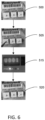
- step 520 the user physically changes the dials of the device index 250 using the tool back to the network IP address copied from step 500, thereby returning the controllers 106 IP address.
- FIG. 6 of step 500 illustrates the network IP address before being changed by the user in step 505.
- Step 505 illustrates the user using a tool to change the MSD dial of device index 250.
- Step 515 illustrates the device display 240 verifying that the unlock code has been accepted by the controller 106 and that the controller is now in the unlocked state.
- Step 520 illustrates the dials of the device index 250 reset to the network IP address copied from step 500.
- FIG. 7 illustrates a diagram of an example method 700 of the monitoring software of the disclosure.
- the method 700 is run as a periodic task that checks whether the dials of the device index 250 have been physically changed in order to put the controller 106 into the locked or the unlocked state.
- the method 700 is executed by the processing device 210.
- the method first reads the value of the dials set in the device index 250 at step 710.
- step 720 the method checks to see if the device index 250 has been changed to the code for locking the controller 106. If the device index 250 has not changed to the lock code than the method 700 continues and checks if the device index 250 has changed to the unlock code in step 730. If the device index has not changed to the unlock code, then the method 700 goes into a sleep state at step 740 for a preset period of time. After the sleep period terminates the method returns to step 710 to read the device index 250 again.
- step 720 If a lock code is encountered at step 720 the controller 106 is changed to the lock state in step 725 and the method 700 goes into the sleep state of step 740. After the sleep period 740 terminates the method 700 returns to reading the device index 250 again. The controller 106 remains in the locked state until the device index 250 is changed to the unlock state. If the method 700 encounters the unlock code in step 730, the controller's state is changed to the unlocked state in step 735 and the method 700 goes into the sleep state 740. After the sleep period terminates the monitoring software returns to 710 to read the device index 250 again. The controller 106 stays in the unlocked state until the device index 250 is changed to enter the lock code.
- any attempts to make changes to the configuration or firmware of the controller 106 such as for example, upgrading the controller firmware, factory reset of the controller, setting the controller to idle, shutting down the controller, changing or deleting the configuration of an application being run by the controller or a change any runtime data such as setpoints would be rejected and not allowed to proceed.
- a notification would be sent to an operator's station monitoring the controller 106 such as for example operator station 116 of system 100 indicating the rejection of an attempted change to a locked controller.
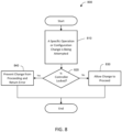
- FIG. 8 illustrates an example method 800 for the enforcement software of the disclosure.
- the method 800 is executed by the processing device 210 and is triggered when a specific attempt to change a specific operation or configuration of the controller 106 is detected as indicated in step 810.
- the method 800 checks to see if the controller is in a locked state. If the controller is in an unlocked state, the attempted change to the controller is allowed to proceed by step 830 and method 800 terminates. However, if the method 800 encounters that the controller 106 is in a locked state then any attempted change to the controller 106 is prevented from proceeding at step 840 and an error is returned to operators' station 116, informing the user of the attempted change to the controller 106.
- the term "communicate,” as well as derivatives thereof, encompasses both direct and indirect communication.
- the term “or” is inclusive, meaning and/or.
- the phrase “associated with,” as well as derivatives thereof, may mean to include, be included within, interconnect with, contain, be contained within, connect to or with, couple to or with, be communicable with, cooperate with, interleave, juxtapose, be proximate to, be bound to or with, have, have a property of, have a relationship to or with, or the like.
- phrases "at least one of,” when used with a list of items, means that different combinations of one or more of the listed items may be used, and only one item in the list may be needed.
- “at least one of: A, B, and C” includes any of the following combinations: A, B, C, A and B, A and C, B and C, and A and B and C.
Landscapes
- Engineering & Computer Science (AREA)
- Theoretical Computer Science (AREA)
- General Engineering & Computer Science (AREA)
- Software Systems (AREA)
- Computer Security & Cryptography (AREA)
- Computer Hardware Design (AREA)
- Physics & Mathematics (AREA)
- General Physics & Mathematics (AREA)
- Automation & Control Theory (AREA)
- Health & Medical Sciences (AREA)
- Bioethics (AREA)
- General Health & Medical Sciences (AREA)
- Computer And Data Communications (AREA)
- Mobile Radio Communication Systems (AREA)
- Testing And Monitoring For Control Systems (AREA)
- Stored Programmes (AREA)
Abstract
Description
- This disclosure is generally directed to industrial control and automation systems. More specifically, this disclosure relates to a system and method for securing and preventing changes to the configuration and firmware of legacy devices of an industrial process control and automation system.
- Legacy process and safety controllers, gateways, and IO modules used in industrial process control and automation systems have been deployed with older hardware technology that do not have the latest cyber security protections such as for example secure boot, signed firmware, and download verification. These legacy devices and the system platforms supporting these devise also may not have the processing power to provide secure, encrypted, and authenticated communications. The legacy devices rely heavily on layered system security of the automation system. However, if these system protections are defeated, then it is possible for a bad actor to gain access to an engineering workstation or to a process control network to shutdown the legacy devices or worse permanently disable them by loading counterfeit firmware that could cause loss of control, bad control, or even damage to a device to the point where it cannot be recovered.
- This disclosure relates to a system and method for securing and preventing changes to the configuration and firmware of legacy devices of an industrial process control and automation system.
- In a first embodiment, a method is disclosed, the method comprising setting a lock code in a device index of the legacy device. The method further including executing a monitoring program that reads the lock code and sets the legacy device in a locked state and executing an enforcement program that prevents changes to the configuration and firmware of the legacy device when the legacy device is in the locked state. The first embodiment further includes a method for releasing the legacy device from the lock state comprising, setting an unlock code in the device index of the legacy device and executing the monitoring program to read the unlock code and set the legacy device in an unlocked state. The enforcement program allowing changes to the configuration and firmware of the legacy device when the legacy device is in the unlocked state.
- In a second embodiment a system is disclosed comprising a device index associated with a legacy device. The device index is manipulable to enter a lock code and processing circuitry is configured to read the lock code and set the legacy device in a locked state. The device index is further manipulable to enter an unlock code and the processing circuitry is configured to read the unlock code and set the legacy device in an unlocked state.
- Other technical features may be readily apparent to one skilled in the art from the following figures, descriptions, and claims.
- For a more complete understanding of this disclosure, reference is now made to the following description, taken in conjunction with the accompanying drawings, in which:
-
FIG. 1 illustrates an example industrial process control and automation system according to this disclosure; -
FIG.2 illustrates details of an example controller according to this disclosure; -
FIG. 3 illustrates a diagram of an example method for setting the controller in a locked state according to this disclosure; -
FIG. 4 illustrates the device index and device display used in the method ofFIG. 3 according to this disclosure; -
FIG. 5 illustrates a diagram of an example method for setting the controller in an unlocked state according to this disclosure; -
FIG. 6 illustrates the device index and device display used in the method ofFIG. 5 according to this disclosure; -
FIG. 7 illustrates a diagram of an example method for monitoring the device index of the controller according to this disclosure; and -
FIG. 8 illustrates a diagram of an example method for enforcing the locked state of the controller according to this disclosure. - The figures, discussed below, and the various embodiments used to describe the principles of the present invention in this patent document are by way of illustration only and should not be construed in any way to limit the scope of the invention. Those skilled in the art will understand that the principles of the invention may be implemented in any type of suitably arranged device or system.
- This disclosure has the benefit of providing a way to lock down devices used in an industrial process control and automation system such as for example, a controller, a wireless gateway, or an I/O module from any changes to its configuration and firmware. This will prevent a rip and replace of a controller or other device used in the industrial process control and automation system from using counterfeit firmware or from a cyber security attack. This disclosure allows legacy process and safety controllers, gateways, and I/O modules to be protected from cyber security attacks with only a software update to the devices.
-
FIG. 1 illustrates an example industrial process control andautomation system 100 according to this disclosure. As shown inFIG 1 , thesystem 100 includes various components that facilitate production or processing of at least one product or other material. For instance, thesystem 100 is used here to facilitate control over components in one ormultiple plants 101a-101n. Eachplant 101a-101n represents one or more processing facilities (or one or more portions thereof), such as one or more manufacturing facilities for producing at least one product or other material. In general, eachplant 101a-101n may implement one or more processes and can individually or collectively be referred to as a process system. A process system generally represents any system or portion thereof configured to process one or more products or other materials in some manner. - In
FIG. 1 , thesystem 100 is implemented using the Purdue model of process control. In the Purdue model, "Level 0" may include one ormore sensors 102a and one ormore actuators 102b. Thesensors 102a andactuators 102b represent components in a process system that may perform any of a wide variety of functions. For example, thesensors 102a could measure a wide variety of characteristics in the process system, such as temperature, pressure, or flow rate. Also, theactuators 102b could alter a wide variety of characteristics in the process system. Thesensors 102a andactuators 102b could represent any other or additional components in any suitable process system. Each of thesensors 102a includes any suitable structure for measuring one or more characteristics in a process system. Each of theactuators 102b includes any suitable structure for operating on or affecting one or more conditions in a process system. - Each of the
sensors 102a andactuators 102b are connected to at least onenetwork 104 through a respective 1/O module network 104 facilitates interaction with the I/O modules sensors 102a andactuators 102b. For example, thenetwork 104 could transport measurement data from the I/O modules sensors 102a and provide control signals to theactuators 102b through I/O module network 104 could represent any suitable network or combination of networks. As particular examples, thenetwork 104 could represent an Ethernet network, an electrical signal network (such as a HART or FOUNDATION FIELDBUS network), a pneumatic control signal network, or any other or additional type(s) of network(s). - In the Purdue model, "Level 1" may include one or
more controllers 106, which are coupled to thenetwork 104. Among other things, eachcontroller 106 may use the measurements from one ormore sensors 102a to control the operation of one ormore actuators 102b. For example, acontroller 106 could receive measurement data from one or more I/O modules sensors 102a and use the measurement data to generate control signals for one ormore actuators 102b. Eachcontroller 106 includes any suitable structure for interacting with one or more I/O modules more actuators 102b. Eachcontroller 106 could, for example, represent a proportional-integral-derivative (PID) controller or a multivariable controller, such as a Robust Multivariable Predictive Control Technology (RMPCT) controller or other type of controller implementing model predictive control (MPC) or other advanced predictive control (APC). As a particular example, eachcontroller 106 could represent a computing device running a real-time operating system. - Two
networks 108 are coupled to thecontrollers 106. Thenetworks 108 facilitate interaction with thecontrollers 106, such as by transporting data to and from thecontrollers 106. Thenetworks 108 could represent any suitable networks or combination of networks. As a particular example, thenetworks 108 could represent a redundant pair of Ethernet networks, such as a FALTLT TOLERANT ETHERNET (FTE) network from HONEYWELL INTERNATIONAL INC. - At least one switch/
firewall 110 couples thenetworks 108 to twonetworks 112. The switch/firewall 110 may transport traffic from one network to another. The switch/firewall 110 may also block traffic on one network from reaching another network. The switch/firewall 110 includes any suitable structure for providing communication between networks, such as a HONEYWELL CONTROL FIREWALL (CF9) device. Thenetworks 112 could represent any suitable networks, such as an FTE network. - In the Purdue model, "Level 2" may include one or more machine-
level controllers 114 coupled to thenetworks 112. The machine-level controllers 114 perform various functions to support the operation and control of thecontrollers 106, I/O modules sensors 102a, andactuators 102b, which could be associated with a particular piece of industrial equipment (such as a boiler or other machine). For example, the machine-level controllers 114 could log information collected or generated by thecontrollers 106, such as measurement data from thesensors 102a or control signals for theactuators 102b. The machine-level controllers 114 could also execute applications that control the operation of thecontrollers 106, thereby controlling the operation of theactuators 102b. In addition, the machine-level controllers 114 could provide secure access to thecontrollers 106. Each of the machine-level controllers 114 includes any suitable structure for providing access to, control of, or operations related to a machine or other individual piece of equipment. Each of the machine-level controllers 114 could, for example, represent a server computing device running a MICROSOFT WINDOWS operating system. Although not shown, different machine-level controllers 114 could be used to control different pieces of equipment in a process system (where each piece of equipment is associated with one ormore controllers 106,sensors 102a, andactuators 102b). - One or
more operator stations 116 are coupled to thenetworks 112. Theoperator stations 116 represent computing or communication devices providing user access to the machine-level controllers 114, which could then provide user access to the controllers 106 (and possibly thesensors 102a andactuators 102b). As particular examples, theoperator stations 116 could allow users to review the operational history of thesensors 102a andactuators 102b using information collected by thecontrollers 106 and/or the machine-level controllers 114. Theoperator stations 116 could also allow the users to adjust the operation of thesensors 102a,actuators 102b,controllers 106, or machine-level controllers 114. In addition, theoperator stations 116 could receive and display warnings, alerts, or other messages or displays generated by thecontrollers 106 or the machine-level controllers 114. Each of theoperator stations 116 includes any suitable structure for supporting user access and control of one or more components in thesystem 100. Each of theoperator stations 116 could, for example, represent a computing device running a MICROSOFT WINDOWS operating system. - At least one router/
firewall 118 couples thenetworks 112 to twonetworks 120. The router/firewall 118 includes any suitable structure for providing communication between networks, such as a secure router or combination router/firewall. Thenetworks 120 could represent any suitable networks, such as an FTE network. - In the Purdue model, "Level 3" may include one or more unit-
level controllers 122 coupled to thenetworks 120. Each unit-level controller 122 is typically associated with a unit in a process system, which represents a collection of different machines operating together to implement at least part of a process. The unit-level controllers 122 perform various functions to support the operation and control of components in the lower levels. For example, the unit-level controllers 122 could log information collected or generated by the components in the lower levels, execute applications that control the components in the lower levels, and provide secure access to the components in the lower levels. Each of the unit-level controllers 122 includes any suitable structure for providing access to, control of, or operations related to one or more machines or other pieces of equipment in a process unit. Each of the unit-level controllers 122 could, for example, represent a server computing device running a MICROSOFT WINDOWS operating system. Although not shown, different unit-level controllers 122 could be used to control different units in a process system (where each unit is associated with one or more machine-level controllers 114,controllers 106,sensors 102a, andactuators 102b). - Access to the unit-
level controllers 122 may be provided by one ormore operator stations 124. Each of theoperator stations 124 includes any suitable structure for supporting user access and control of one or more components in thesystem 100. Each of theoperator stations 124 could, for example, represent a computing device running a MICROSOFT WINDOWS operating system. - At least one router/
firewall 126 couples thenetworks 120 to twonetworks 128. The router/firewall 126 includes any suitable structure for providing communication between networks, such as a secure router or combination router/firewall. Thenetworks 128 could represent any suitable networks, such as an FTE network. - In the Purdue model, "Level 4" may include one or more plant-
level controllers 130 coupled to thenetworks 128. Each plant-level controller 130 is typically associated with one of theplants 101a-101n, which may include one or more process units that implement the same, similar, or different processes. The plant-level controllers 130 perform various functions to support the operation and control of components in the lower levels. As particular examples, the plant-level controller 130 could execute one or more manufacturing execution system (MES) applications, scheduling applications, or other or additional plant or process control applications. Each of the plant-level controllers 130 includes any suitable structure for providing access to, control of, or operations related to one or more process units in a process plant. Each of the plant-level controllers 130 could, for example, represent a server computing device running a MICROSOFT WINDOWS operating system. - Access to the plant-
level controllers 130 may be provided by one ormore operator stations 132. Each of theoperator stations 132 includes any suitable structure for supporting user access and control of one or more components in thesystem 100. Each of theoperator stations 132 could, for example, represent a computing device running a MICROSOFT WINDOWS operating system. - At least one router/
firewall 134 couples thenetworks 128 to one ormore networks 136. The router/firewall 134 includes any suitable structure for providing communication between networks, such as a secure router or combination router/firewall. Thenetwork 136 could represent any suitable network, such as an enterprise-wide Ethernet or other network or all or a portion of a larger network (such as the Internet). - In the Purdue model, "Level 5" may include one or more enterprise-
level controllers 138 coupled to thenetwork 136. Each enterprise-level controller 138 is typically able to perform planning operations formultiple plants 101a-101n and to control various aspects of theplants 101a-101n. The enterprise-level controllers 138 can also perform various functions to support the operation and control of components in theplants 101a-101n. As particular examples, the enterprise-level controllers 138 could execute one or more order processing applications, enterprise resource planning (ERP) applications, advanced planning, and scheduling (APS) applications, or any other or additional enterprise control applications. Each of the enterprise-level controllers 138 includes any suitable structure for providing access to, control of, or operations related to the control of one or more plants. Each of the enterprise-level controllers 138 could, for example, represent a server computing device running a MICROSOFT WINDOWS operating system. In this document, the term "enterprise" refers to an organization having one or more plants or other processing facilities to be managed. Note that if asingle plant 101a is to be managed, the functionality of the enterprise-level controller 138 could be incorporated into the plant-level controller 130. - Access to the enterprise-
level controllers 138 may be provided by one or more operator stations 140. Each of the operator stations 140 includes any suitable structure for supporting user access and control of one or more components in thesystem 100. Each of the operator stations 140 could, for example, represent a computing device running a MICROSOFT WINDOWS operating system. - Various levels of the Purdue model can include other components, such as one or more databases. The database(s) associated with each level could store any suitable information associated with that level or one or more other levels of the
system 100. For example, ahistorian 141 can be coupled to thenetwork 136. Thehistorian 141 could represent a component that stores various information about thesystem 100. Thehistorian 141 could, for instance, store information used during production scheduling and optimization. Thehistorian 141 represents any suitable structure for storing and facilitating retrieval of information. Although shown as a single centralized component coupled to thenetwork 136, thehistorian 141 could be located elsewhere in thesystem 100, or multiple historians could be distributed in different locations in thesystem 100. - In particular embodiments, the various controllers and operator stations in
FIG. 1 may represent computing devices. For example, each of thecontrollers controllers network interface 146, such as one or more Ethernet interfaces or wireless transceivers. Also, each of theoperator stations more processing devices 148 and one ormore memories 150 for storing instructions and data used, generated, or collected by the processing device(s) 148. Each of theoperator stations network interface 152, such as one or more Ethernet interfaces or wireless transceivers. - The
system 100 also includes agateway device 160. Thegateway 160 integrates theplants 101a through 101n and thenetwork 136 with acloud network 162 and anoperator station 164. Thegateway 160 can include a ONEWIRELESS gateway providing high availability and mesh capability. Thegateway 160 may also include Common Embedded Platform for communication protocols as well as redundancy, design, and security features. Thegateway 160 includes Intuition and Experion for system connectivity, distributed system architecture, and service oriented architecture. Thegateway 160 includes OPC unified architecture (UA) for legacy and future system integration. - A communication stack to the
cloud network 162 includes OPC UA and its core services for synchronous and asynchronous data publication, alarms and event publication, history data transfer, blind record or "BLOB" transfer, and the like. Other cloud protocols can be supported as an alternative to or in addition to OPC UA. The other cloud protocols can have similar services including event streaming to an event hub in the cloud and data access services. Thegateway 160 provides secure guard traffic flow bi-directionally to protect both the cloud and the on premise systems and devices (such as the devices within theplant 101a as well as theenterprise controllers 138 and the operator stations 140. - In an embodiment, the
networks 136 can represent a cloud network configured to facilitate communication between thegateway 160 and at least one of theenterprise controllers 138, the operator stations 140, thehistorian 141, or one ormore plants 101b-101n via wireless communication. - Although
FIG. 1 illustrates one example of an industrial process control andautomation system 100, various changes may be made toFIG. 1 . For example, a control and automation system could include any number of sensors, actuators, I/O modules, controllers, servers, operator stations, networks, risk managers, and other components. Additionally, for example, thenetworks system 100 inFIG. 1 is for illustration only. Components could be added, omitted, combined, or placed in any other suitable configuration according to particular needs. Further, particular functions have been described as being performed by particular components of thesystem 100. This is for illustration only. In general, control and automation systems are highly configurable and can be configured in any suitable manner according to particular needs. -
FIG. 2 illustrates an example of acontroller 106 according to this disclosure. As shown inFIG. 2 , thecontroller 106 includes abus system 205, which supports communication between at least oneprocessing device 210, at least onestorage device 215, at least onecommunications unit 220, at least one input/output (I/O)unit 225, adevice display 240 and adevice index 250. - The
processing device 210 executes instructions that may be loaded into amemory 230. Theprocessing device 210 may include any suitable number(s) and type(s) of processors or other devices in any suitable arrangement. Example types ofprocessing devices 210 include microprocessors, microcontrollers, digital signal processors, field programmable gate arrays, application specific integrated circuits, and discreet circuitry. - The
memory 230 and apersistent storage 235 are examples ofstorage devices 215, which represent any structure(s) capable of storing and facilitating retrieval of information (such as data, program code, and/or other suitable information on a temporary or permanent basis). Thememory 230 may represent a random access memory or any other suitable volatile or non-volatile storage device(s). Thepersistent storage 235 may contain one or more components or devices supporting longer-term storage of data, such as a ready only memory, hard drive, Flash memory, or optical disc. - The
communications unit 220 supports communications with other systems or devices. For example, thecommunications unit 220 could include a network interface card such as for example an Ethernet network interface for communication over theEthernet network 104 or a wireless transceiver facilitating communications over thenetwork 136. Thecommunications unit 220 may support communications through any suitable physical or wireless communication link(s). - The I/
O unit 225 allows for input and output of data. For example, the I/O unit 225 may provide a connection for user input through a keyboard, mouse, keypad, touchscreen, or other suitable input device. The I/O unit 225 may also send output to a display, printer, or other suitable output device. - The
device display 240, may be comprised of a multi-character, multiline message display, a single alphanumeric character display or various light emitting diodes (LED) that can use colors or blinking effects to provide information to a user. Thedisplay device 240 is used to display information and inform a user of thecontrollers 106 current operating condition and status. For thedisplay device 240 of the present disclosure an exemplary single-line, multi-character display will be used to explain the benefits of the present disclosure, however, it will be understood by those skilled in the art that other displays including those explained above may be used to provide information to a user at thecontroller 106. - The
device index 250 is a set of electrical switches or other switch type devices that can be physically changed by hand or with the aid of a tool such as for example, a screwdriver. The electrical switches may include a single or multiple dual in-line package (DIP) or rotary dial switches. Other electrical devices used in the industry to switch between functions may also be used, such as for example, shorting jumper pins, manipulating push pins or simply using patch cords that can be physically plugged into sockets to set a code for locking or unlocking the controller. - Controllers used in industry particularly those that communicate data using an Ethernet internet protocol (IP) include electrical switches used to enter an internet IP address or portions of the IP address such as the last octet used for identifying a controller in the Ethernet network. In such controllers it would be an advantage to use the Ethernet IP switches to also enter a lock and unlock code for the controller.
- For the ease of explaining the benefits of the present disclosure, the
device index 250 will be explained using a set of rotary dial switches that include three dials that each can be set to a unique number from 0-9. As can be seen inFIGS. 4 and6 , the left most dial represents the most significant digit (MSD) and the right most dial the least significant digit (LSD). The dials are used to complete the IP address for thecontroller 106 serving to provide network interface identification and location addressing of thecontroller 106 within an Ethernet network usedsystem 100 such as forexample Ethernet network 104. Other electrical switches known in the industry and used for changing the state of thecontroller 106 or setting an IP network address, such as those explained above may be substituted for the rotary dials to comprise thedevice index 250. - It should be noted that this disclosure will use a
controller 106 as an example to explain the invention, it will be understood by those skilled in the art, that other devices used in thesystem 100, such as for example, the I/O modules gateway 160, as well asmachine controller 114,unit controller 122 andplant controller 130 that connect to any of theethernet networks system 100 and that use a device index can be used to practice the invention. - The disclosure provides a
legacy controller 106 with a security lock state by setting a lock code using thedevice index 250. Thecontroller 106 may also be set to an unlocked state by setting an unlock code using thedevice index 250. A monitoring software program reads the lock or unlock code set indevice index 250. An enforcement software program prevents certain controller operations from executing if thecontroller 106 is in the locked state. Both the monitoring software program and enforcement software program is stored inmemory 230 and is executed by theprocessing device 210. The monitoring software periodically monitors thedevice index 250 and places thecontrollers 106 in a locked or unlocked state based on the code set on the dials of thedevice index 250. The enforcement software is executed when certain changes to thecontroller 106 configuration and firmware is being attempted. The enforcement software checks and ascertain if thecontroller 106 is in a locked or an unlocked state, preventing the attempted changes and returning errors if the controller is set in the locked state. -
FIGS. 3 and4 illustrate the method for setting the controller in a locked state. Instep 300, a user, such as plant operator or other authorized user copies or makes note of the numeric settings that are currently set on the dials of thedevice index 250. - Next in
step 305 the user changes thedevice index 250 to the lock code using a tool such as for example, a screwdriver to set the lock code using the dials of thedevice index 250. As was explained above, other devices can be used to enter a lock or unlock code including for example, DIP switches, jumper pins, push pins or patch cords that can be physically manipulated to set a code for locking or unlocking thecontroller 106. With a rotary dial, the lock code may be a preset single numeral or a multiple number combination that the monitoring software understands is the code for locking thecontroller 106. The setting code is entered in any combination on the rotary dials of thedevice index 250. For example, a numeral from 0-9 can be set using only the MSD of the dials or a numeral from 0-9 set in the LSD dial of thedevice index 250. Additionally, a more complex code may be used by setting the appropriate numerals in all three dials, such as for example, 123, or 789, etc. In still another more sophisticated method, a combination of three different codes followed by a set time interval between the code settings can be used for setting the lock code. For example, setting 123 in the dials, waiting 10 seconds, setting 234 in the dials, and waiting another 10 seconds and finally 567. - Next in
step 310 the monitoring software reads the code set into the dials of thedevice index 250. If a match is made with the lock code expected by the monitoring software thecontrollers 106 state is changed to locked. Instep 315 the locked state of thecontroller 106 is visually indicated to the user on thedevice display 240 confirming that the lock code has been accepted and that thecontroller 106 is now in the locked state. Finally, instep 320 the user physically changes the dials of thedevice index 250 back to the network IP address copied fromstep 300. - In
FIG. 4 step 300 illustrates the network IP address before being changed by the user instep 305. Step 305 illustrates the user using a tool to change the MSD dial ofdevice index 250. Step 315 illustrates an example of thedevice display 240 verifying to the user that the controller has accepted thelock code 106 and that the controller is now in a locked state. Finally,step 320 illustrates the dials of thedevice index 250 reset to the network IP address copied fromstep 300. -
FIGS. 5 and6 illustrate the method for setting the controller into an unlocked state. Instep 500, the user copies or makes note of the numeric settings that are currently set on the dials of thedevice index 250. - Next in
step 505 the user changes thedevice index 250 to the unlock code using a tool such as for example, a screwdriver to set the unlock code using the dials of thedevice index 250. The unlock code may be a preset single numeral or a multiple number combination that the monitoring software understands is the code for unlocking thecontroller 106, as was explained above for the setting the lock code. - Next in
step 510 the monitoring software reads the code set into the dials of thedevice index 250. If a match is made with the unlock code expected by the monitoring software the controllers state is changed to unlocked. Instep 515 the unlocked state of thecontroller 106 is visually indicated to the user on thedevice display 240 confirming that the unlock code has been accepted and that thecontroller 106 is now in the locked state. - Finally, in
step 520 the user physically changes the dials of thedevice index 250 using the tool back to the network IP address copied fromstep 500, thereby returning thecontrollers 106 IP address. -
FIG. 6 ofstep 500 illustrates the network IP address before being changed by the user instep 505. Step 505 illustrates the user using a tool to change the MSD dial ofdevice index 250. Step 515 illustrates thedevice display 240 verifying that the unlock code has been accepted by thecontroller 106 and that the controller is now in the unlocked state. Step 520 illustrates the dials of thedevice index 250 reset to the network IP address copied fromstep 500. -
FIG. 7 illustrates a diagram of anexample method 700 of the monitoring software of the disclosure. Themethod 700 is run as a periodic task that checks whether the dials of thedevice index 250 have been physically changed in order to put thecontroller 106 into the locked or the unlocked state. Themethod 700 is executed by theprocessing device 210. The method first reads the value of the dials set in thedevice index 250 atstep 710. Next instep 720 the method checks to see if thedevice index 250 has been changed to the code for locking thecontroller 106. If thedevice index 250 has not changed to the lock code than themethod 700 continues and checks if thedevice index 250 has changed to the unlock code instep 730. If the device index has not changed to the unlock code, then themethod 700 goes into a sleep state atstep 740 for a preset period of time. After the sleep period terminates the method returns to step 710 to read thedevice index 250 again. - If a lock code is encountered at
step 720 thecontroller 106 is changed to the lock state instep 725 and themethod 700 goes into the sleep state ofstep 740. After thesleep period 740 terminates themethod 700 returns to reading thedevice index 250 again. Thecontroller 106 remains in the locked state until thedevice index 250 is changed to the unlock state. If themethod 700 encounters the unlock code instep 730, the controller's state is changed to the unlocked state instep 735 and themethod 700 goes into thesleep state 740. After the sleep period terminates the monitoring software returns to 710 to read thedevice index 250 again. Thecontroller 106 stays in the unlocked state until thedevice index 250 is changed to enter the lock code. - Upon the locking of the
controller 106 any attempts to make changes to the configuration or firmware of thecontroller 106, such as for example, upgrading the controller firmware, factory reset of the controller, setting the controller to idle, shutting down the controller, changing or deleting the configuration of an application being run by the controller or a change any runtime data such as setpoints would be rejected and not allowed to proceed. A notification would be sent to an operator's station monitoring thecontroller 106 such as forexample operator station 116 ofsystem 100 indicating the rejection of an attempted change to a locked controller. -
FIG. 8 illustrates anexample method 800 for the enforcement software of the disclosure. Themethod 800 is executed by theprocessing device 210 and is triggered when a specific attempt to change a specific operation or configuration of thecontroller 106 is detected as indicated instep 810. Next instep 820 themethod 800 checks to see if the controller is in a locked state. If the controller is in an unlocked state, the attempted change to the controller is allowed to proceed bystep 830 andmethod 800 terminates. However, if themethod 800 encounters that thecontroller 106 is in a locked state then any attempted change to thecontroller 106 is prevented from proceeding atstep 840 and an error is returned to operators'station 116, informing the user of the attempted change to thecontroller 106. - It may be advantageous to set forth definitions of certain words and phrases used throughout this patent document. The term "communicate," as well as derivatives thereof, encompasses both direct and indirect communication. The terms "include" and "comprise," as well as derivatives thereof, mean inclusion without limitation. The term "or" is inclusive, meaning and/or. The phrase "associated with," as well as derivatives thereof, may mean to include, be included within, interconnect with, contain, be contained within, connect to or with, couple to or with, be communicable with, cooperate with, interleave, juxtapose, be proximate to, be bound to or with, have, have a property of, have a relationship to or with, or the like. The phrase "at least one of," when used with a list of items, means that different combinations of one or more of the listed items may be used, and only one item in the list may be needed. For example, "at least one of: A, B, and C" includes any of the following combinations: A, B, C, A and B, A and C, B and C, and A and B and C.
- The description in the present application should not be read as implying that any particular element, step, or function is an essential or critical element that must be included in the claim scope. The scope of patented subject matter is defined only by the allowed claims. Moreover, none of the claims is intended to invoke 35 U.S.C. § 112(f) with respect to any of the appended claims or claim elements unless the exact words "means for" or "step for" are explicitly used in the particular claim, followed by a participle phrase identifying a function. Use of terms such as (but not limited to) "mechanism," "module," "device," "unit," "component," "element," "member," "apparatus," "machine," "system," or "controller" within a claim is understood and intended to refer to structures known to those skilled in the relevant art, as further modified or enhanced by the features of the claims themselves and is not intended to invoke 35 U.S.C. § 112(f).
- While this disclosure has described certain embodiments and generally associated methods, alterations and permutations of these embodiments and methods will be apparent to those skilled in the art. Accordingly, the above description of example embodiments does not define or constrain this disclosure. Other changes, substitutions, and alterations are also possible without departing from the spirit and scope of this disclosure, as defined by the following claims.
Claims (4)
- A method for securing and preventing changes to the configuration and firmware of a legacy device of an industrial process control and automation system, the method comprising:setting a lock code in a device index of the legacy device;executing a monitoring program that reads the lock code and sets the legacy device in a locked state; andexecuting an enforcement program that prevents changes to the configuration and firmware of the legacy device when the legacy device is in the locked state.
- The method of Claim 1, wherein the method further includes releasing the legacy device from the lock state, the method comprising:setting an unlock code in the device index of the legacy device;executing the monitoring program to read the unlock code and set the legacy device in an unlocked state; andexecuting the enforcement program to allow changes to the configuration and firmware of the legacy device when the legacy device is in the unlocked state.
- A system comprising:a device index associated with a legacy device, the device index manipulable to enter a lock code; andprocessing circuitry configured to read the lock code and set the legacy device in a locked state.
- The system of claim 3, wherein the device index is manipulated to enter an unlock code; and
the processing circuitry is configured to read the unlock code and set the legacy device in an unlocked state.
Applications Claiming Priority (1)
| Application Number | Priority Date | Filing Date | Title |
|---|---|---|---|
| US202263323356P | 2022-03-24 | 2022-03-24 |
Publications (1)
| Publication Number | Publication Date |
|---|---|
| EP4250156A1 true EP4250156A1 (en) | 2023-09-27 |
Family
ID=85505506
Family Applications (1)
| Application Number | Title | Priority Date | Filing Date |
|---|---|---|---|
| EP23160291.3A Pending EP4250156A1 (en) | 2022-03-24 | 2023-03-06 | System and method for providing security to legacy devices |
Country Status (4)
| Country | Link |
|---|---|
| US (1) | US12361114B2 (en) |
| EP (1) | EP4250156A1 (en) |
| CN (1) | CN116804868B (en) |
| AU (2) | AU2023201130A1 (en) |
Families Citing this family (1)
| Publication number | Priority date | Publication date | Assignee | Title |
|---|---|---|---|---|
| US12361114B2 (en) * | 2022-03-24 | 2025-07-15 | Honeywell International Inc. | System and method for providing security to legacy devices |
Citations (3)
| Publication number | Priority date | Publication date | Assignee | Title |
|---|---|---|---|---|
| US20160134586A1 (en) * | 2014-11-06 | 2016-05-12 | Azbil Corporation | Network control method and system |
| US20180224819A1 (en) * | 2017-02-07 | 2018-08-09 | Johnson Controls Technology Company | Building management system with automatic remote server query for hands free commissioning and configuration |
| EP4141724A1 (en) * | 2021-08-23 | 2023-03-01 | Rockwell Automation Asia Pacific Business center Pte. Ltd. | Systems and methods for providing security and tamper detection in i/o systems |
Family Cites Families (15)
| Publication number | Priority date | Publication date | Assignee | Title |
|---|---|---|---|---|
| JP2004030102A (en) * | 2002-06-25 | 2004-01-29 | Sony Corp | Information storage device, memory access control system and method, and computer program |
| KR101305497B1 (en) * | 2006-08-14 | 2013-09-05 | 삼성전자주식회사 | Client Computer, Remote Control System And Remote Control Method |
| EP2273746A1 (en) | 2009-06-26 | 2011-01-12 | Alcatel Lucent | Method to control legacy devices |
| US20160365680A1 (en) * | 2015-06-09 | 2016-12-15 | Motorola Mobility Llc | Method and apparatus for initiating a change in state of an electronic device through a connector receptacle |
| US20170046531A1 (en) * | 2015-08-14 | 2017-02-16 | Strong Bear Llc | Data encryption method and system for use with cloud storage |
| US9882893B2 (en) * | 2015-09-15 | 2018-01-30 | Honeywell International Inc. | System and method for secured password management for industrial devices |
| US10275962B2 (en) * | 2015-12-14 | 2019-04-30 | Afero, Inc. | Apparatus and method for internet of things (IOT) security lock and notification device |
| US10530762B2 (en) * | 2016-03-09 | 2020-01-07 | Google Llc | Electing whether to unify passcodes |
| DK201670616A1 (en) * | 2016-06-12 | 2018-01-22 | Apple Inc | Devices and Methods for Accessing Prevalent Device Functions |
| US20190171820A1 (en) * | 2017-12-04 | 2019-06-06 | Phoenix Technologies, Ltd. | Securing Resumption from Sleep Mode Using a Storage Medium Authentication Credential |
| US11062013B2 (en) * | 2018-03-02 | 2021-07-13 | Bently Nevada, Llc | Two-step hardware authentication |
| US10776102B1 (en) * | 2019-05-10 | 2020-09-15 | Microsoft Technology Licensing, Llc | Securing firmware installation on USB input device |
| KR20210073714A (en) | 2019-12-11 | 2021-06-21 | 이노디지털 주식회사 | Integrated IoT control system based on device status recognition |
| US11540138B2 (en) * | 2020-06-19 | 2022-12-27 | Johnson Controls Tyco IP Holdings LLP | Interactive local information interface |
| US12361114B2 (en) * | 2022-03-24 | 2025-07-15 | Honeywell International Inc. | System and method for providing security to legacy devices |
-
2022
- 2022-09-14 US US17/944,473 patent/US12361114B2/en active Active
-
2023
- 2023-02-24 AU AU2023201130A patent/AU2023201130A1/en not_active Abandoned
- 2023-03-06 EP EP23160291.3A patent/EP4250156A1/en active Pending
- 2023-03-10 CN CN202310230229.3A patent/CN116804868B/en active Active
-
2025
- 2025-01-08 AU AU2025200123A patent/AU2025200123A1/en active Pending
Patent Citations (3)
| Publication number | Priority date | Publication date | Assignee | Title |
|---|---|---|---|---|
| US20160134586A1 (en) * | 2014-11-06 | 2016-05-12 | Azbil Corporation | Network control method and system |
| US20180224819A1 (en) * | 2017-02-07 | 2018-08-09 | Johnson Controls Technology Company | Building management system with automatic remote server query for hands free commissioning and configuration |
| EP4141724A1 (en) * | 2021-08-23 | 2023-03-01 | Rockwell Automation Asia Pacific Business center Pte. Ltd. | Systems and methods for providing security and tamper detection in i/o systems |
Also Published As
| Publication number | Publication date |
|---|---|
| AU2025200123A1 (en) | 2025-01-23 |
| CN116804868A (en) | 2023-09-26 |
| US12361114B2 (en) | 2025-07-15 |
| US20230306100A1 (en) | 2023-09-28 |
| AU2023201130A1 (en) | 2023-10-12 |
| CN116804868B (en) | 2026-05-12 |
Similar Documents
| Publication | Publication Date | Title |
|---|---|---|
| AU2021201799B2 (en) | Apparatus and method for using a distributed systems architecture (DSA) in an internet of things (IoT) edge appliance | |
| EP3350959B1 (en) | System and method for secured password management for industrial devices | |
| AU2016369256B2 (en) | Apparatus and method for using an internet of things edge secure gateway | |
| US9912737B2 (en) | Method and system for modular interoperable distributed control | |
| US20160234241A1 (en) | Infrastructure monitoring tool for collecting industrial process control and automation system risk data | |
| AU2025200123A1 (en) | System and method for providing security to legacy devices | |
| EP2942683B1 (en) | Method and apparatus for tracking changes in an industrial controller | |
| AU2016357206B2 (en) | Deployment assurance checks for monitoring industrial control systems | |
| AU2018258112B2 (en) | Consolidated enterprise view of cybersecurity data from multiple sites | |
| US20160234243A1 (en) | Technique for using infrastructure monitoring software to collect cyber-security risk data | |
| US20210302932A1 (en) | I/o mesh architecture for a safety instrumented system | |
| EP3213310B1 (en) | Method and apparatus for providing early warning of extraction of module under power | |
| US20170257782A1 (en) | Remote resolution of customer issues enabled by integrating multiple communication technologies using a handheld configurator | |
| US10637841B2 (en) | Apparatus and method for using a security appliance with IEC 61131-3 | |
| WO2018200330A1 (en) | Inferred detection of data replication errors of source applications by enterprise applications | |
| HK1159264A (en) | Method for determining a security step and security manager |
Legal Events
| Date | Code | Title | Description |
|---|---|---|---|
| PUAI | Public reference made under article 153(3) epc to a published international application that has entered the european phase |
Free format text: ORIGINAL CODE: 0009012 |
|
| STAA | Information on the status of an ep patent application or granted ep patent |
Free format text: STATUS: REQUEST FOR EXAMINATION WAS MADE |
|
| 17P | Request for examination filed |
Effective date: 20230306 |
|
| AK | Designated contracting states |
Kind code of ref document: A1 Designated state(s): AL AT BE BG CH CY CZ DE DK EE ES FI FR GB GR HR HU IE IS IT LI LT LU LV MC ME MK MT NL NO PL PT RO RS SE SI SK SM TR |
|
| STAA | Information on the status of an ep patent application or granted ep patent |
Free format text: STATUS: EXAMINATION IS IN PROGRESS |
|
| 17Q | First examination report despatched |
Effective date: 20251028 |
|
| GRAP | Despatch of communication of intention to grant a patent |
Free format text: ORIGINAL CODE: EPIDOSNIGR1 |
|
| STAA | Information on the status of an ep patent application or granted ep patent |
Free format text: STATUS: GRANT OF PATENT IS INTENDED |
|
| INTG | Intention to grant announced |
Effective date: 20260413 |