EP4250017A1 - Heating device, nip forming device, and image forming apparatus - Google Patents
Heating device, nip forming device, and image forming apparatus Download PDFInfo
- Publication number
- EP4250017A1 EP4250017A1 EP23161000.7A EP23161000A EP4250017A1 EP 4250017 A1 EP4250017 A1 EP 4250017A1 EP 23161000 A EP23161000 A EP 23161000A EP 4250017 A1 EP4250017 A1 EP 4250017A1
- Authority
- EP
- European Patent Office
- Prior art keywords
- rotator
- peripheral surface
- inner peripheral
- sheet
- heating device
- Prior art date
- Legal status (The legal status is an assumption and is not a legal conclusion. Google has not performed a legal analysis and makes no representation as to the accuracy of the status listed.)
- Granted
Links
Images




Classifications
-
- G—PHYSICS
- G03—PHOTOGRAPHY; CINEMATOGRAPHY; ANALOGOUS TECHNIQUES USING WAVES OTHER THAN OPTICAL WAVES; ELECTROGRAPHY; HOLOGRAPHY
- G03G—ELECTROGRAPHY; ELECTROPHOTOGRAPHY; MAGNETOGRAPHY
- G03G15/00—Apparatus for electrographic processes using a charge pattern
- G03G15/20—Apparatus for electrographic processes using a charge pattern for fixing, e.g. by using heat
- G03G15/2003—Apparatus for electrographic processes using a charge pattern for fixing, e.g. by using heat using heat
- G03G15/2014—Apparatus for electrographic processes using a charge pattern for fixing, e.g. by using heat using heat using contact heat
- G03G15/2053—Structural details of heat elements, e.g. structure of roller or belt, eddy current, induction heating
-
- G—PHYSICS
- G03—PHOTOGRAPHY; CINEMATOGRAPHY; ANALOGOUS TECHNIQUES USING WAVES OTHER THAN OPTICAL WAVES; ELECTROGRAPHY; HOLOGRAPHY
- G03G—ELECTROGRAPHY; ELECTROPHOTOGRAPHY; MAGNETOGRAPHY
- G03G15/00—Apparatus for electrographic processes using a charge pattern
- G03G15/20—Apparatus for electrographic processes using a charge pattern for fixing, e.g. by using heat
- G03G15/2003—Apparatus for electrographic processes using a charge pattern for fixing, e.g. by using heat using heat
- G03G15/2014—Apparatus for electrographic processes using a charge pattern for fixing, e.g. by using heat using heat using contact heat
- G03G15/2017—Structural details of the fixing unit in general, e.g. cooling means, heat shielding means
- G03G15/2025—Structural details of the fixing unit in general, e.g. cooling means, heat shielding means with special means for lubricating and/or cleaning the fixing unit, e.g. applying offset preventing fluid
-
- G—PHYSICS
- G03—PHOTOGRAPHY; CINEMATOGRAPHY; ANALOGOUS TECHNIQUES USING WAVES OTHER THAN OPTICAL WAVES; ELECTROGRAPHY; HOLOGRAPHY
- G03G—ELECTROGRAPHY; ELECTROPHOTOGRAPHY; MAGNETOGRAPHY
- G03G2215/00—Apparatus for electrophotographic processes
- G03G2215/20—Details of the fixing device or porcess
- G03G2215/2003—Structural features of the fixing device
- G03G2215/2016—Heating belt
- G03G2215/2035—Heating belt the fixing nip having a stationary belt support member opposing a pressure member
Definitions
- Embodiments of the present disclosure generally relate to a heating device heating an inner peripheral surface of a rotator, a nip forming device including the heating device, and an image forming apparatus including the heating device.
- one type of image forming apparatus includes a fixing device employing a surf system or a belt system.
- the surf system or the belt system includes a rotator having a thin thickness.
- Japanese Unexamined Patent Application Publication No. 2005-292335 discloses the fixing device.
- a heater such as a halogen heater heats the inner peripheral surface of the rotator.
- Rotator holders such as flanges support both ends of the inner peripheral surface of the rotator in a longitudinal direction of the rotator so that the inner peripheral surface of the rotator can slide on the rotator holders.
- Lubricant is applied and interposed between the rotator and the rotator holders such as flanges in order to reduce frictional resistance and prevent the occurrence of abnormal noise.
- the lubricant is a liquid or semi-solid substance that have lubricity. When the temperature of the rotator holder becomes high, the rotator holder heats the lubricant, which generates fine particles and ultrafine particles from volatile substances included in the lubricant. The fine particles and ultrafine particles may leak to the outside of the image forming apparatus.
- Japanese Unexamined Patent Application Publication No. 2007-72105 discloses a fixing device including a flange that has a rotator guide (in other words, a holding portion), and the rotator guide has inclined grooves that move the lubricant toward the longitudinal center of the rotator.
- FIG. 6A is a graph illustrating results of experiments.
- the lubricant was heated by a hot plate, and concentrations of generated fine particles were measured in temperatures from 190°C. to 250°C. From the results of the experiments, it can be seen that the fine particles start to come out all at once at 200°C. or more.
- the graph of FIG. 6A illustrates a relation between the temperature rise of silicone oil and fluorine grease used as the lubricant and the concentration of fine particles generated from the lubricant (specifically, the number of fine particles including ultrafine particles (FP/LTFP) generated per 1 cm3).
- the fine particles in this specification are fine particles and ultrafine particles that can be measured by the measurement method and under the measurement conditions in the following test, and the particle diameter is preferably in a range from 5.6 nm to 560 nm.
- a liquid or semi-solid lubricating substance in a sample container was heated in a chamber of 1 m3 (with a ventilating frequency of 5 times) in accordance with Japanese Industrial Standards (JIS) A 1901.
- An aluminum plate of 50 mm ⁇ 50 mm ⁇ 5 mm provided with a recess having a diameter of 22 mm and a depth of 2 mm was used as a sample container.
- a sample was disposed in the recess.
- the sample container on which the sample was placed on a hot plate of a heating device (Clean Hot Plate MH-180CS manufactured by AS ONE Corporation, Controller MH-3CS manufactured by AS ONE Corporation). The sample was heated at a preset temperature of 250°C.
- the number concentration of FP/LTFP in the chamber was measured with a measuring device (FAST MOBILITY PARTICLE SIZER (FMPS) Model 3091 manufactured by TSI Incorporated), with the Use Averaging Interval at Export of 30 seconds. Fluorine grease and silicone oil were used as lubricants with a sample amount of 36 microliters ( ⁇ l).
- the solid line indicates the number concentration of FP/LTFP generated from the fluorine grease
- the alternate long and short dash line indicates the number concentration of FP/UFP generated from the silicone oil.
- the horizontal axis indicates the temperature of the hot plate. Since the temperature rise of the hot plate and the temperature rise of the lubricant change substantially in synchronization with each other, the temperature of the hot plate is regarded as the temperature of the lubricant here.
- FIG. 6B is a graph illustrating the measured results.
- temperatures were measured in the inner peripheral surface and the outer peripheral surface of the rotator holder (that is, the flange) of the fixing device.
- FIG. 6C is a graph illustrating measurement results.
- the timing at which the fine particles rapidly increase is about 3 minutes from the start of printing. This timing substantially coincides with the time at which the inner peripheral surface of the flange illustrated in FIG. 6C reaches 200°C. or more.
- the present inventors found that the inner peripheral surface of the flange is the place in which the fine particles are generated.
- the outer peripheral surface of the flange also reaches 200°C. in about 9 minutes, but before that, fine particles have already been generated.
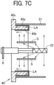
- FIGS. 7A to 7C are views of a part of the fixing device to illustrate a flange 40 with the inner peripheral surface of the flange 40 heated by radiant heat from a halogen heater 23.
- the radiant heat from the halogen heater 23 directly acts on the inner peripheral surface of the flange 40.
- the fixing device illustrated in FIGS. 7B and 7C includes a shield plate to shield the radiant heat, but the heated shield plate heats the inner peripheral surface of the flange 40 as illustrated in FIGS. 7B and 7C .
- the lubricant flows on the inner peripheral surface of the flange 40 as illustrated by light black portions in FIG. 7C and is heated to generate the fine particles.
- An object of the present disclosure is to prevent the lubricant from moving to the inner peripheral surface of the rotator holder.
- the heating device includes a rotator, a heater, a rotator holder, and lubricant.
- the heater heats an inner peripheral surface of the rotator.
- the rotator holder holds an end of the inner peripheral surface of the rotator in a longitudinal direction of the rotator.
- the rotator holder includes a holding portion, a flange portion, and an inclined surface.
- the holding portion is in contact with the end of the inner peripheral surface of the rotator such that the end of the inner peripheral surface of the rotator is slidable on the holding portion.
- the flange portion is in contact with an end of the rotator in the longitudinal direction and extends outward in a radial direction of a loop of the rotator.
- the inclined surface is inclined in a direction away from the inner peripheral surface of the rotator facing the inclined surface from the holding portion toward the flange portion.
- the lubricant is in at least one of a liquid state or a semi-solid state and applied to the rotator holder.
- This specification also describes a nip forming device, a fixing device, and an image forming apparatus that include the heating device.
- the heating device can prevent the lubricant from moving to the inner peripheral surface of the rotator holder.
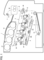
- FIG. 1 With reference to FIG. 1 , the following describes a schematic configuration and operation of an image forming apparatus 1 including a fixing device 20 according to an embodiment of the present disclosure and next describes details of the fixing device 20.
- FIG. 1 is a schematic view of the image forming apparatus 1.
- the image forming apparatus 1 is a color laser printer.
- the image forming apparatus 1 includes four image forming devices 4Y, 4M, 4C, and 4K in a center portion of a body of the image forming apparatus 1.
- the image forming devices 4Y, 4M, 4C, and 4K have substantially the same configuration except for containing different color developers (e.g., toners) of yellow (Y), magenta (M), cyan (C), and black (K), respectively, corresponding to color separation components of color images.
- color developers e.g., toners
- each of the image forming devices 4Y, 4M, 4C, and 4K includes a photoconductor 5 that has a drum shape and serves as a latent image bearer, a charger 6 that charges the surface of the photoconductor 5, a developing device 7 that supplies toner to the surface of the photoconductor 5, and a cleaner 8 that cleans the surface of the photoconductor 5.
- FIG. 1 illustrates reference numerals assigned to the photoconductor 5, the charger 6, the developing device 7, and the cleaner 8 of the image forming device 4K that forms a black toner image.
- reference numerals for the image forming devices 4Y, 4C, and 4M that form yellow, cyan, and magenta toner images, respectively, are omitted for convenience.
- An exposure device 9 is disposed below the image forming devices 4Y, 4M, 4C, and 4K and exposes the outer circumferential surfaces of the respective photoconductors 5 with laser beams.
- the exposure device 9 includes a light source, a polygon mirror, an f- ⁇ lens, and a reflection mirror to irradiate the surface of the photoconductor 5 with the laser beam according to image data.
- a transfer device 3 is disposed above the image forming devices 4Y, 4M, 4C, and 4K.
- the transfer device 3 includes an intermediate transfer belt 30 serving as an intermediate transferor and four primary transfer rollers 31 serving as primary transfer devices.
- the transfer device 3 also includes a secondary transfer roller 36 as a secondary transfer device and a secondary transfer backup roller 32.
- the transfer device 3 includes a cleaning backup roller 33, a tension roller 34, and a belt cleaner 35.
- the intermediate transfer belt 30 is an endless belt stretched taut across the secondary transfer backup roller 32, the cleaning backup roller 33, and the tension roller 34.
- a driver drives and rotates the secondary transfer backup roller 32 in a counterclockwise direction
- the intermediate transfer belt 30 rotates in a direction indicated by an arrow in FIG. 1 by friction therebetween.
- the four primary transfer rollers 31 sandwich the intermediate transfer belt 30 together with the four photoconductors 5, forming four primary transfer nips between the intermediate transfer belt 30 and the photoconductors 5, respectively.
- Each primary transfer roller 31 is connected to a power supply.
- the power supply applies a predetermined direct current (DC) voltage and/or alternating current (AC) voltage to each of the primary transfer rollers 31.
- the intermediate transfer belt 30 is interposed between the secondary transfer roller 36 and the secondary transfer backup roller 32 to form a secondary transfer nip. Similar to the primary transfer rollers 31, the secondary transfer roller 36 is connected to a power supply that applies a predetermined direct current (DC) voltage and/or alternating current (AC) voltage to the secondary transfer roller 36.
- DC direct current
- AC alternating current
- the belt cleaner 35 includes a cleaning brush and a cleaning blade that contact an outer circumferential surface of the intermediate transfer belt 30.
- a waste toner conveyance tube extends from the belt cleaner 35 to an inlet of a waste toner container to convey waste toner collected from the intermediate transfer belt 30 by the belt cleaner 35 to the waste toner container.
- a bottle holder 2 disposed in an upper portion of the image forming apparatus 1 accommodates four toner bottles 2Y, 2C, 2M, and 2K detachably attached to the bottle holder 2.
- the toner bottles 2Y, 2C, 2M, and 2K contain fresh yellow, cyan, magenta, and black toners to be supplied to the developing devices 7 of the image forming devices 4Y, 4C, 4M, and 4K, respectively.
- the fresh toner is supplied from the toner bottles 2Y, 2M, 2C, and 2K to the respective developing devices 7 through toner supply tubes connected between the toner bottles 2Y, 2M, 2C, and 2K and the respective developing devices 7.
- a sheet feeding tray 10 and a sheet feeding roller 11 are disposed.
- the sheet feeding tray 10 contains sheets P as recording media.
- the sheet feeding roller 11 feeds the sheet P as a recording medium from the sheet feeding tray 10.
- the recording medium as a conveyed object that is the sheet P may be plain paper, thick paper, postcards, envelopes, thin paper, coated paper, art paper, tracing paper, overhead projector (OHP) transparencies, and the like.
- the image forming apparatus may include a bypass feeder.
- the image forming apparatus 1 includes a conveyance path R to convey the sheet P from the sheet feeding tray 10 to a sheet ejection roller pair 13 via the secondary transfer nip.
- the sheet ejection roller pair 13 ejects the sheet P outside the image forming apparatus 1.
- a pair of timing rollers 12 is disposed upstream from the secondary transfer nip in a direction in which the sheet P is conveyed (hereinafter simply referred to as a sheet conveyance direction).
- the pair of timing rollers 12 sends out the sheet P fed from the sheet feeding roller 11 toward the secondary transfer nip at a predetermined time.
- the fixing device 20 is disposed downstream from the secondary transfer roller 36 in the sheet conveyance direction.
- the fixing device 20 receives the sheet P bearing a toner image and fixes the toner image onto the sheet P.
- the sheet ejection roller pair 13 On the conveyance path R downstream from the fixing device 20 in the sheet conveyance direction, the sheet ejection roller pair 13 is disposed.
- the sheet ejection roller pair 13 ejects the sheet P onto an output tray 14.
- the output tray 14 is disposed on a top surface of the image forming apparatus 1.
- a driver drives and rotates the photoconductor 5 in each of the image forming devices 4Y, 4M, 4C, and 4K clockwise in FIG. 1 , and the charger 6 uniformly charges the surface of the photoconductor 5 in a predetermined polarity.
- the exposure device 9 emits laser beams onto the charged outer circumferential surfaces of the photoconductors 5, respectively, thus forming electrostatic latent images on the photoconductors 5.
- the image data used to expose the respective photoconductors 5 is monochrome image data produced by decomposing a desired full color image into yellow, cyan, magenta, and black image data.
- the developing devices 7 supply yellow, cyan, magenta, and black toners to the electrostatic latent images formed on the photoconductors 5, visualizing the electrostatic latent images as yellow, cyan, magenta, and black toner images, respectively.
- the secondary transfer backup roller 32 is driven and rotated counterclockwise in FIG. 1 , rotating the intermediate transfer belt 30 in the direction indicated by the arrow in FIG. 1 by friction therebetween.
- the power supply applies a constant voltage or a constant-current control voltage having a polarity opposite the polarity of the toner to the primary transfer roller 31, creating a transfer electric field at each primary transfer nip formed between the photoconductor 5 and the primary transfer roller 31.
- the transfer electric fields generated at the primary transfer nips transfer the yellow, magenta, cyan, and black toner images from the photoconductors 5 onto the intermediate transfer belt 30, respectively, such that the yellow, magenta, cyan, and black toner images are superimposed successively on the intermediate transfer belt 30.
- a full color toner image is formed on the outer circumferential surface of the intermediate transfer belt 30.
- the sheet feeding roller 11 disposed in the lower portion of the image forming apparatus 1 is driven and rotated to feed the sheet P from the sheet feeding tray 10 toward the pair of timing rollers 12 through the conveyance path R.
- the pair of timing rollers 12 temporarily stops conveying the sheet P.
- the pair of timing rollers 12 is rotated at a predetermined time to convey the sheet P to the secondary transfer nip in synchronization with the full-color toner image formed on the intermediate transfer belt 30 reaching the secondary transfer nip.
- the power supply applies a transfer voltage to the secondary transfer roller 36.
- the transfer voltage has the polarity opposite the polarity of the charged toner contained in the full-color toner image formed on the intermediate transfer belt 30. As a result, a transfer electric field is generated at the secondary transfer nip.
- the transfer electrical field transfers the full-color toner image from the intermediate transfer belt 30 onto the sheet P at a time. After the secondary transfer of the full color toner image from the intermediate transfer belt 30 onto the sheet P, residual toner that is not transferred to the sheet P remains on the intermediate transfer belt 30.
- the belt cleaner 35 removes the residual toner from the intermediate transfer belt 30. The removed toner is conveyed and collected into the waste toner container disposed inside the image forming apparatus 1.
- the sheet P bearing the full color toner image is conveyed to the fixing device 20 that fixes the full color toner image onto the sheet P.
- the sheet P bearing the fixed full-color toner image is ejected by the sheet ejection roller pair 13 onto the outside of the image forming apparatus 1 and is stacked on the output tray 14.
- the image forming apparatus 1 may form a monochrome toner image by using any one of the four image forming devices 4Y, 4C, 4M, and 4K or may form a bicolor toner image or a tricolor toner image by using two or three of the image forming devices 4Y, 4C, 4M, and 4K.
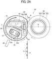
- FIGS. 2A and 2B are schematic cross-sectional views of the fixing device 20.
- the fixing device 20 is one example of a nip forming device.
- the fixing device 20 includes a fixing belt 21 as a rotator and a pressure roller 22 as an opposed rotator in contact with the outer peripheral surface of the fixing belt 21.
- the fixing device 20 also includes a halogen heater 23, a nip formation pad 24, a stay 25, a reflector 26, a shield 27, and a temperature sensor 28.
- the halogen heater serves as a heat source to heat the fixing belt 21.
- the nip formation pad 24 is in contact with the inner peripheral surface of the fixing belt 21.
- the pressure roller 22 as a pressure rotator presses against the nip formation pad 24 via the fixing belt 21 to form a fixing nip N.
- the stay 25 supports the nip formation pad 24.
- the halogen heater 23 radiates radiant heat, and the reflector 26 reflects the radiant heat to the fixing belt 21.
- the shield 27 shields the radiant heat radiated from the halogen heater 23.
- the temperature sensor 28 serves as a temperature detector to detect the temperature of the fixing belt 21.
- the fixing belt 21 is a thin, flexible, endless belt (which may be a film). Specifically, the fixing belt 21 includes a base layer forming the inner peripheral surface of the fixing belt 21.
- the base layer is made of metal such as nickel or steel use stainless (SUS) or resin such as polyimide (PI).
- the fixing belt 21 includes a release layer made of tetrafluoroethylene-perfluoroalkylvinylether copolymer (PFA), polytetrafluoroethylene (PTFE) or the like.
- the release layer is the outermost layer.
- an elastic layer made of rubber such as silicone rubber, silicone rubber foam, or fluoro rubber may be interposed between the base layer and the release layer.
- the fixing belt 21 not including the elastic layer has a small thermal capacity that improves a fixing property.
- the fixing belt 21 includes the elastic layer no thinner than 80 ⁇ m.
- the elastic layer not thinner than 80 ⁇ m elastically deforms to absorb the slight surface asperities in the fixing belt 21, thus preventing uneven gloss of the toner image on the sheet P.
- the fixing belt 21 in the present embodiment is thin and has a decreased loop diameter.
- the base layer of the fixing belt 21 is designed to have a thickness of from 20 ⁇ m to 50 ⁇ m
- the elastic layer is designed to have a thickness of from 80 ⁇ m to 300 ⁇ m
- the release layer is designed to have a thickness of from 3 ⁇ m to 50 ⁇ m.
- the fixing belt 21 is designed to have a total thickness not greater than 1 mm.
- the loop diameter of the fixing belt 21 is set in a range of 20 mm to 40 mm.
- the fixing belt 21 may have a total thickness not greater than 0.20 mm and more preferably not greater than 0.16 mm.
- the loop diameter of the fixing belt 21 may be 30 mm or less.
- the pressure roller 22 includes a cored bar 22a, an elastic layer 22b disposed on the surface of the cored bar 22a, and a release layer 22c disposed on the surface of the elastic layer 22b.
- the elastic layer 22b is made of foamed silicone rubber, silicon rubber, or fluoro-rubber.
- the release layer 22c is made of PFA or PTFE.
- the pressurization assembly including a spring presses the pressure roller 22 against the nip formation pad 24 via the fixing belt 21.
- the pressure roller 22 abuts on the nip formation pad 24 via the fixing belt 21.
- deformation of the elastic layer 22b of the pressure roller 22 forms the fixing nip N having a predetermined width in the sheet conveyance direction.
- a driver such as a motor disposed inside the image forming apparatus 1 drives and rotates the pressure roller 22.
- a driving force of the driver is transmitted from the pressure roller 22 to the fixing belt 21 at the fixing nip N, thus rotating the fixing belt 21 in accordance with rotation of the pressure roller 22 by friction between the fixing belt 21 and the pressure roller 22.
- flanges 40 as rotator holders are inserted into both ends of the fixing belt 21 to rotatably hold the fixing belt 21.
- the flanges 40 do not support both ends of the fixing belt 21.
- the pressure roller 22 is a solid roller.
- the pressure roller 22 may be a hollow roller.
- a heat source such as the halogen heater may be disposed inside the pressure roller 22.
- the elastic layer 22b of the pressure roller 22 may be made of solid rubber.
- the elastic layer of the pressure roller 22 may be made of sponge rubber.
- the sponge rubber is preferable to the solid rubber because the sponge rubber has enhanced thermal insulation that draws less heat from the fixing belt 21.
- the halogen heater 23 is disposed inside the loop of the fixing belt 21 and upstream from the fixing nip N in the sheet conveyance direction. Specifically, as illustrated in FIG. 2A , the halogen heater 23 is disposed, in the sheet conveyance direction, upstream from an imaginary line L passing through the center Q of the fixing nip N in the sheet conveyance direction and the rotation center O of the pressure roller 22, that is, in a lower portion from the line L in FIG. 2A .
- the power source situated inside the image forming apparatus 1 supplies power to the halogen heater 23 so that the halogen heater 23 generates heat. Output of the power source is controlled based on the temperature of the outer peripheral surface of the fixing belt 21 detected by the temperature sensor 28.
- Such heating control of the halogen heater 23 adjusts the temperature of the fixing belt 21 to a desired fixing temperature.
- a temperature sensor that detects the temperature of the pressure roller 22 may be disposed, and the controller may predict the temperature of the fixing belt 21 based on the temperature of the pressure roller 22 detected by the temperature sensor.
- two halogen heaters 23 are disposed in the loop of the fixing belt 21, but one halogen heater 23 or three or more halogen heaters 23 may be disposed in the loop of the fixing belt 21 based on the size of the sheet P used in the image forming apparatus 1. However, when the cost of the halogen heater 23 itself, a space inside the loop of the fixing belt 21, and the like are considered, a desirable number of the halogen heaters 23 is two or less.
- the radiant heat radiated from the heater heats the fixing belt 21.
- the heater may be a resistive heat generator or carbon heater instead of the halogen heater.
- the nip formation pad 24 includes a base pad 24a and a sliding sheet 24b disposed on the surface of the base pad 24a, the surface facing the fixing belt 21.
- the sliding sheet 24b is a low friction member.
- the base pad 24a extends in the axial direction of the fixing belt 21 or the axial direction of the pressure roller 22.
- the base pad 24a receives a pressing force from the pressure roller 22 and determines a shape of the fixing nip N.
- the shape of the fixing nip N is a flat shape but may be a concave shape or another shape.
- the sliding sheet 24b is disposed to reduce sliding friction when the fixing belt 21 rotates.
- the base pad 24a itself made of a low-friction member enables a configuration not including the sliding sheet 24b.
- the base pad 24a is made of a heat-resistant material having a heat-resistant temperature of 200°C. or more to prevent deformation of the nip formation pad 24 due to heat in the toner fixing temperature range, thereby ensuring a stable state of the fixing nip N and stabilizing qualities in the image on the ejected sheet P.
- the material of the base pad 24a may be general heat-resistant resins such as polyethersulfone (PES), polyphenylene sulfide (PPS), liquid crystal polymer (LCP), polyethernitrile (PEN), polyamide-imide (PAI), and polyetheretherketone (PEEK).
- the stay 25 supports and fixes the base pad 24a.
- the stay 25 prevents the nip formation pad 24 from being bent by the pressure from the pressure roller 22 to form the fixing nip having a uniform width along the axial direction of the pressure roller 22.
- the stay 25 is made of metal having an increased mechanical strength, such as stainless steel or iron, to prevent bending of the nip formation pad 24.
- the base pad 24a is preferably made of a rigid material to ensure the strength of the base pad 24a.
- the material of the base pad 24a may be resins such as liquid crystal polymers (LCP), metals, ceramics, or the like.
- the reflector 26 is fixed and supported by the stay 25 so as to face the halogen heater 23.
- the reflector 26 reflects the radiant heat and light emitted from the halogen heater 23 toward the fixing belt 21 to prevent the heat from being transmitted to the stay 25 and the like, thereby efficiently heating the fixing belt 21 and saving energy.
- the material of the reflector 26 may be aluminum, stainless steel, or the like.
- the reflector made of an aluminum base on which silver having low emissivity (in other words, high reflectivity) is evaporated improves the heating efficiency of the fixing belt 21.
- a surface of the reflector 26 facing the halogen heater 23 is formed to spread over the inner peripheral surface of the fixing belt 21.
- the reflector 26 has a portion facing a lower portion of the halogen heater 23 and extending along a circumferential direction of the fixing belt 21 to shield radiant heat radiated from both ends of the halogen heater 23.
- the above-described portion of the reflector 26 does not extend over the entire length of the reflector 26 in the longitudinal direction of the reflector 26.
- the shield 27 is made of a metal plate such as a SUS plate having heat resistance and a thickness of 0.1 mm to 1.0 mm so as to have a cross-sectional shape along the inner peripheral surface of the fixing belt 21.
- the cross-sectional shape of the shield 27 has ends and is not a ring closed in the circumferential direction.
- the cross-sectional shape of the shield 27 is an arc.
- the shield 27 is rotatable around the halogen heater 23.
- the shield 27 is rotatable along the circumferential direction of the fixing belt 21.
- a circumferential region of the fixing belt 21 has a directly heated region directly facing the halogen heater 23 and heated by the halogen heater 23.
- the circumferential region of the fixing belt 21 has a non-directly heated region in which a member other than the shield 27, such as the reflector 26, the stay 25, or the nip formation pad 24 exists between the halogen heater 23 and the fixing belt 21.
- the shield 27 thermally shields between the halogen heater 23 and the fixing belt 21, the shield 27 is disposed at a shielding position facing the directly heated region as illustrated in FIG. 2A .
- the shield 27 does not thermally shield between the halogen heater 23 and the fixing belt 21, the shield 27 is moved to a retracted position facing the non-directly heated region as illustrated in FIG. 2B .
- the shield 27 is retracted to a space above upper portions of the reflector 26 and the stay 25.
- the shield 27 is preferably made of ceramic or metal such as aluminum, iron, or SUS because the shield 27 requires heat resistance.
- FIG. 3 is a perspective view of a part of the fixing device 20 according to the present embodiment. As illustrated in FIG. 3 , the flanges 40 as rotator holders are inserted into both ends of the fixing belt 21, respectively.
- the flanges 40 come into contact with both ends of the inner peripheral surface of the fixing belt 21 in a longitudinal direction of the fixing belt 21, respectively, and both ends of the inner peripheral surface of the fixing belt 21 slide on the flanges 40. As a result, the flanges 40 rotatably hold the fixing belt 21.
- the fixing device 20 includes a pair of side plates that supports and fixes the flanges 40, the halogen heater 23, and the stay 25.
- the flange 40 has a cylindrical portion with a notch 40m. The notch 40m faces the pressure roller 22 so that the flange 40 does not interfere with the pressure roller 22.
- the cylindrical portion of the flange 40 has a C-shape.
- the following describes a fixing operation of the fixing device 20 according to the present embodiment.
- the image forming apparatus 1 illustrated in FIG. 1 is powered on, power is supplied to the halogen heater 23, and the driver starts driving and rotating the pressure roller 22 clockwise in FIGS. 2A and 2B .
- the rotation of the pressure roller 22 drives the fixing belt 21 to rotate counterclockwise in FIGS. 2A and 2B by friction between the fixing belt 21 and the pressure roller 22.
- the sheet P bearing the unfixed toner image T formed in the image forming processes described above is conveyed in the sheet conveyance direction A1 in FIG. 2A while guided by a guide plate and enters the fixing nip N formed between the fixing belt 21 and the pressure roller 22 pressed against the fixing belt 21.
- the toner image T is fixed onto the sheet P under heat from the fixing belt 21 heated by the halogen heater 23 and pressure exerted between the fixing belt 21 and the pressure roller 22.
- the sheet P bearing the fixed toner image T is sent out from the fixing nip N and conveyed in a direction indicated by an arrow A2 in FIG. 2A .
- the separator separates the sheet P from the fixing belt 21.
- the sheet P separated from the fixing belt 21 is ejected by the sheet ejection roller pair 13 depicted in FIG. 1 to the outside of the image forming apparatus 1 and stacked on the output tray 14.
- the flange 40 in a heating device 29 is described below.
- the heating device 29 includes the fixing belt 21, the halogen heater 23, and the flanges 40 as illustrated in FIG. 3 .
- the flanges 40 may be made of a heat-resistant resin such as liquid crystal polymer. The following describes the flanges 40 according to a first embodiment to a fifth embodiment. It goes without saying that these embodiments are examples and do not limit the present disclosure.
- the first embodiment is described below with reference to FIGS. 4A and 4B .
- FIGS. 4A and 4B are top cross-sectional views and top views of the flange 40 and the fixing belt 21.
- the flange 40 includes a cylindrical portion 40a having an inner peripheral surface 40b and a flange portion 40c.
- the cylindrical portion 40a serves as a holding portion.
- the cylindrical portions 40a are in contact with both ends of the inner peripheral surface of the fixing belt 21, and the inner peripheral surface of the fixing belt 21 slides on the cylindrical portions 40a.
- the flange portion 40c extends outward in a radial direction of the loop of the fixing belt that is a direction orthogonal to the longitudinal direction of the fixing belt 21. Both ends of the fixing belt 21 in the longitudinal direction are sandwiched by the flange portions 40c.
- the longitudinal direction is a longitudinal direction of a general fixing belt and is a rotation axis direction of the fixing belt.
- the longitudinal direction is a direction parallel to the fixing belt.
- the flange portion 40c has a portion orthogonal to the longitudinal direction of the fixing belt 21.
- the flange 40 has a substantially L shape.
- the vertical portion of the L shape is the flange portion 40c
- the horizontal portion of the L shape is a portion of the flange supporting the end of the fixing belt 21.
- Lubricant LA is applied to the cylindrical portion 40a of the flange 40 so that the fixing belt 21 smoothly slides on the cylindrical portion 40a.
- the flange 40 has an inclined surface 40d between the cylindrical portion 40a and the flange portion 40c.
- the inclined surface 40d is inclined in a direction away from the inner peripheral surface of the fixing belt 21 facing the inclined surface 40d from the cylindrical portion 40a toward the flange portion 40c.
- the inclined surface 40d has a point adjacent to the flange portion 40c and farther from the inner peripheral surface than another point adjacent to the cylindrical portion 40a. In other words, the closer a point on the inclined surface 40d is to the flange portion 40c, the farther the point on the inclined surface 40d is from the inner peripheral surface of the fixing belt 21. That is, a diameter of a circle formed by the inclined surface 40d decreases outward in the longitudinal direction.
- the inclined surface 40d forms a space as a lubricant reservoir to store the lubricant LA.
- the lubricant LA may be in a liquid state, a semi-solid state, or a mixture thereof.
- the "liquid state” is a colloidal sol in which a solid is contained in a liquid
- the "semi-solid state” is a gel in which the sol is solidified in a jelly state.
- the inclination angle ⁇ of the inclined surface 40d with respect to the longitudinal direction may be set in a range of 3° to 8°, for example.
- the inclined surface 40d may be a conical surface formed from an outer end of the cylindrical portion 40a in the longitudinal direction toward the flange portion 40c.
- the length of the inclined surface 40d in the longitudinal direction is set, for example, to be 8 mm.
- the farthest portion of the inclined surface 40d from the outer surface of the cylindrical portion 40a in a direction orthogonal to the longitudinal direction may be set to be away from the outer surface of the cylindrical portion 40a by, for example, 0.5 mm to 1 mm.
- the thickness of the farthest portion described above may be set in a range of 1.1 mm to 1.5 mm, for example.
- the thickness of the flange 40 is a length from the inner peripheral surface 40b to an outer surface of the flange 40 in the radial direction of the loop of the fixing belt 21 orthogonal to the longitudinal direction of the fixing belt 21 as the rotator. According to results of temperature measurement illustrated in FIG. 5A , which is described below, setting the thickness of the farthest portion to 1.1 mm or more can suppress the temperature rise at the farthest portion to 200°C. or less.
- the flange 40 may have a circumferential annular groove 40e formed between the farthest portion of the inclined surface 40d and the base of the flange portion 40c.
- the annular groove 40e increases the space as the lubricating reservoir to store the lubricant LA. Setting the thickness from the inner peripheral surface 40b to the bottom of the annular groove 40e to 1.1 mm or more can suppress the temperature rise at the bottom to 200°C. or less.
- a second embodiment is described below with reference to FIGS. 4C and 4D .
- the flange 40 has a plurality of inclined grooves 40f.
- the inclined groove has a bottom surface that is the inclined surface as illustrated in FIGS. 4A and 4B .
- the inclined groove 40f extends between the cylindrical portion 40a and the flange portion 40c in the longitudinal direction of the fixing belt 21.
- the plurality of inclined grooves 40f are formed at equal intervals in the circumferential direction of the cylindrical portion 40a. In other words, the plurality of inclined grooves 40f is arranged in a rotation direction of the fixing belt 21.
- an outer end of the inclined groove 40f in the longitudinal direction is connected to the base of the flange portion 40c.
- the outer end of the inclined groove 40f in the longitudinal direction is connected to the annular groove 40g.
- a portion between the inclined grooves 40f is not inclined and extends from the cylindrical portion 40a in the longitudinal direction of the fixing belt. Portions between the inclined grooves 40f form a comb-tooth shape.
- a third embodiment is described below with reference to FIG. 4E and 4F .
- the flange 40 according to the third embodiment has spiral inclined grooves 40h instead of the inclined grooves 40f as illustrated in FIGS. 4C and 4D .
- the spiral inclined groove 40h is inclined in the rotation direction of the fixing belt 21 (that is indicated by an arrow in each of FIGS. 4E and 4F ) and extends toward the inner surface of the flange portion 40c.
- the spiral inclined grooves 40h are arranged in the rotation direction.
- An inclination angle of the spiral inclined groove 40h in the direction indicated by the arow may be set in a range of 1° to 70°, for example.
- a plurality of spiral inclined grooves 40h are formed at equal intervals in the circumferential direction of the cylindrical portion 40a.
- an outer end of the spiral inclined groove 40h in the longitudinal direction is connected to the base of the flange portion 40c.
- the outer end of the spiral inclined groove 40h in the longitudinal direction is connected to an annular groove 40i.
- a portion between the spiral inclined grooves 40h is not inclined and extends from the cylindrical portion 40a in the longitudinal direction of the fixing belt. Portions between the spiral inclined grooves 40h form the comb-tooth shape.
- a fourth embodiment is described below with reference to FIG. 4G .
- the flange 40 includes a first cylindrical portion 40a that is the cylindrical portion 40a as illustrated in FIG. 4A , a circumferential annular groove 40k formed on the inner side of the first cylindrical portion 40a in the longitudinal direction, and a second cylindrical portion 40j formed inside from the annular groove 40k.
- the second cylindrical portion 40j is smaller in diameter than the first cylindrical portion 40a so as to be close to the inner peripheral surface of the fixing belt 21 and not in contact with the inner peripheral surface of the fixing belt 21.
- the inclined surface 40d forms a first lubricant reservoir
- the annular groove 40k forms a second lubricant reservoir. Forming two lubricant reservoirs as described above can more surely prevent the lubricant from leaking than the flange 40 configured as illustrated in FIG. 4A .
- a fifth embodiment is described below with reference to FIG. 4H .
- the flange 40 includes the first cylindrical portion 40a having the inner peripheral surface 40b and the flange portion 40c.
- the first cylindrical portions 40a are in contact with both ends of the inner peripheral surface of the fixing belt 21, and the inner peripheral surface of the fixing belt 21 slides on the cylindrical portions 40a.
- the flange portion 40c extends outward in the radial direction of the loop of the fixing belt that is a direction perpendicular to the rotational axis direction of the fixing belt 21. Both ends of the fixing belt 21 in the longitudinal direction are sandwiched by the flange portions.
- the flange 40 has the circumferential annular groove 40k formed on the inner side of the first cylindrical portion 40a in the longitudinal direction and the second cylindrical portion 40j formed inside from the annular groove 40k.
- the second cylindrical portion 40j is smaller in diameter than the first cylindrical portion 40a so as to be close to the inner peripheral surface of the fixing belt 21 and not in contact with the inner peripheral surface of the fixing belt 21.
- the annular groove 40k forms the lubricant reservoir.
- the inclined surface 40d is omitted from the flange 40 according to the fourth embodiment in FIG. 4G . Since the annular groove 40k forms the first lubricant reservoir, the inclined surface 40d can be omitted.
- the present embodiments can prevent the occurrence of the fine particles including the ultrafine particles.
- FIG. 5A is a graph illustrating a relation between a thickness of the flange 40 and a temperature of an outer peripheral surface of the flange 40. From the graph of FIG. 5A , it is understood that the temperature of the outer peripheral surface of the flange was 200°C. or less when the flange had a thickness of 1.1 mm or more.
- FIG. 5B is the cross-sectional view of the flange 40 according to the first embodiment illustrated in FIG. 4B that was used for the temperature measurements that gave the results of FIG. 5A .
- the flange 40 was made of a heat-resistant resin such as a liquid crystal polymer.
- the flange 40 had a thickness of 1.1 mm at a position of the bottom of the annular groove 40e at which the flange is thinnest.
- FIG. 5C illustrates measurement results. As can be seen from the graph in FIG. 5C , the temperature of the inner peripheral surface of the flange 40 exceeded 200°C. after continuous printing for 200 seconds, but the temperature of the outer peripheral surface of the flange 40 did not exceed 200°C. even after continuous printing for 600 seconds.
- FIG. 5D is a graph illustrating the measurement results.
- the concentration of generated fine particles including the ultrafine particles was measured with a fast mobility particle sizer (FMPS3091 manufactured by Tokyo Dylec Corp.).
- a fluorine grease of 70 mg and a silicone oil of 35 mg were used as the lubricant. As illustrated in the graph of FIG. 5D , it was confirmed that the fine particles including the ultrafine particles were not almost generated.
- the image forming apparatus to which the features of this disclosure are applied is not limited to the printer illustrated in FIG. 1 but may be other types of printers, copiers, facsimile machines, or multifunction peripherals having these capabilities.
- the embodiments of the present disclosure are applied to the fixing device incorporated in the electrophotographic image forming apparatus as illustrated in FIG. 1 .
- the present disclosure is not limited to this.
- the embodiments of the present disclosure may be applied to a heating device other than the fixing device, such as a drying device that is included in an inkjet image forming apparatus and dries liquid such as ink applied to a sheet.
- FIG. 8 illustrates an inkjet image forming apparatus 2000 including a drying device 206 according to an embodiment of the present disclosure.
- the inkjet image forming apparatus 2000 illustrated in FIG. 8 includes an image reading device 202, an image forming device 203, a sheet supplying device 204, the drying device 206, and an output section 207.
- a sheet aligning apparatus 3000 is disposed beside the inkjet image forming apparatus 2000.
- the sheet supplying device 204 feeds a sheet such as a sheet of paper as a recording medium in the inkjet image forming apparatus 2000.
- the image forming device 203 discharges ink from a liquid discharge head 214 to the sheet according to image data of a document read by the image reading device 202 or print data instructed to print by a terminal, to form an image on the sheet.
- the sheet bearing the image is selectively guided to a conveyance passage 222 or a conveyance passage 223.
- the sheet passes through the drying device 206.
- the drying device 206 accelerates the drying of the ink on the sheet.
- the sheet is then guided to the output section 207 or the sheet aligning apparatus 3000.
- the sheet aligning apparatus 3000 aligns and places the sheets guided to the sheet aligning apparatus 3000.
- the drying device 206 includes a heating belt 291 as a first rotator, a heating roller 292 as a second rotator, a first heater 293 as the heat source that heats the heating belt 291, a second heater 294 as the heat source that heats the heating roller 292, a nip formation pad 295, a stay 296 as a support, a reflector 297, and belt holders 298 as the rotator holders that hold the heating belt 291 such that the heating belt 291 can rotate.
- the heating belt 291, the first heater 293, and the belt holder 298 to which the lubricant is applied configure a heating device 299 of the present disclosure.
- the belt holder 298 may have any one of the shapes illustrated in FIGS. 4A to 4H and include the cylindrical portion 40a, the flange portion 40c, and the inclined surface 40d.
- the nip formation pad 295 contacts an outer peripheral surface of the heating roller 292 via the heating belt 291 to form a nip N between the heating belt 291 and the heating roller 292. That is, the heating roller 292 serves as the pressure rotator to press against the nip formation pad 295 via the heating belt 291 as the rotator to form the nip N.
- the heating roller 292 serves as the pressure rotator to press against the nip formation pad 295 via the heating belt 291 as the rotator to form the nip N.
- the heating belt 291 is rotatably held by the pair of belt holders 298 disposed at both ends of the heating belt 291 in the longitudinal direction of the heating belt 291.
- the drying device 206 prevents the temperature rise of the belt holders 298 and effectively reduces the generation of the fine particles including the ultrafine particles.
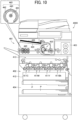
- An image forming apparatus 4000 that is illustrated in FIG. 10 includes a laminator 401, an image forming device 402, a fixing device 403, and a sheet feeding device 404 as a recording-medium supplier.
- the image forming device 402 includes a plurality of image forming units 411C, 411M, 411Y, and 411Bk, an exposure device 412, and a transfer device 413.
- the laminator 401 is a heating device that applies heat and pressure to two sheets between which a recording medium is inserted, to thermally press the sheets to the recording medium.
- the laminator 401 includes a sheet supplier 420, a sheet separator 430, and heat and pressure rollers 440.
- the sheet supplier 420 supplies a sheet 450.
- the sheet separator 430 separates the sheet supplied from the sheet supplier 420 into two sheets.
- the heat and pressure rollers 440 as rotators convey the two separated sheets between which the recording medium is inserted, while applying heat and pressure to the sheets and the recording medium.
- a heat source such as a heater 441 heats the heat and pressure roller 440.
- a pair of rotator holders such as a pair of bearings 442 rotatably holds both ends of an inner peripheral surface of the heat and pressure roller 440 in the longitudinal direction of the heat and pressure roller 440.
- All heat and pressure rollers 440 illustrated in FIG. 10 each include the heater 441 and the pair of bearings 442 as illustrated in an enlarged view of the heat and pressure roller 440 in FIG. 10 .
- the heating device according to the present disclosure is configured by the heat and pressure roller 440 as the rotator, the heater 441, and the bearing 442 to which the lubricant is applied.
- the bearing 442 may have any one of the shapes illustrated in FIGS. 4A to 4H and include the cylindrical portion 40a, the flange portion 40c, and the inclined surface 40d.
- the image forming device 402 forms an image and transfers the image onto the supplied sheet P.
- the sheet P bearing the transferred image is conveyed to the fixing device 403, which fixes the image onto the sheet P.
- the image forming and transfer processes performed by the image forming device 402 with the plurality of image forming units 411C, 411M, 411Y, and 411Bk, the exposure device 412, and the transfer device 413 are basically the same as those described in the above embodiment.
- the fixing process performed by the fixing device 403 is basically the same as that described in the above embodiment. Therefore, a redundant description thereof is omitted.
- the sheet P subjected to the fixing process is then conveyed to the laminator 401 and inserted between two sheets separated from each other. Then, the heat and pressure rollers 440 apply heat and pressure to the sheet P sandwiched between the two sheets to thermally press the sheets and the sheet P. The sheets and the sheet P thus thermally pressed are ejected to the outside of the image forming apparatus 4000.
- the laminator 401 including the heat and pressure rollers 440 prevents the temperature rise of the bearings that hold the heat and pressure rollers 440 and effectively reduces the generation of the fine particles including the ultrafine particles.
Landscapes
- Physics & Mathematics (AREA)
- General Physics & Mathematics (AREA)
- Fixing For Electrophotography (AREA)
Abstract
Description
- Embodiments of the present disclosure generally relate to a heating device heating an inner peripheral surface of a rotator, a nip forming device including the heating device, and an image forming apparatus including the heating device.
- In image forming apparatuses such as a copier, a printer, a facsimile machine, and a multifunction peripheral of them, one type of image forming apparatus includes a fixing device employing a surf system or a belt system. The surf system or the belt system includes a rotator having a thin thickness. For example,
Japanese Unexamined Patent Application Publication No. 2005-292335 - Lubricant is applied and interposed between the rotator and the rotator holders such as flanges in order to reduce frictional resistance and prevent the occurrence of abnormal noise. The lubricant is a liquid or semi-solid substance that have lubricity. When the temperature of the rotator holder becomes high, the rotator holder heats the lubricant, which generates fine particles and ultrafine particles from volatile substances included in the lubricant. The fine particles and ultrafine particles may leak to the outside of the image forming apparatus.
- Recently, Reducing the fine particles in addition to the volatile organic compounds (VOC) is requested from the viewpoint of environmental protection. In particular, environmental standards such as Blue Angel in Germany regulates an upper limit value of fine particles having a diameter of 1 µm or less and being discharged from the apparatus.
- Conventionally, a configuration has been adopted in which the lubricant between the rotator holder such as the flange and the rotator is moved inward in the longitudinal direction of the rotator so as not to leak the lubricant to the outside. For example,
Japanese Unexamined Patent Application Publication No. 2007-72105 - However, the heater such as the halogen heater is inside the loop of the rotator. The lubricant moved toward the center of the rotator approaches the heater and may be exposed to a high temperature.
FIG. 6A is a graph illustrating results of experiments. In the experiments, the lubricant was heated by a hot plate, and concentrations of generated fine particles were measured in temperatures from 190°C. to 250°C. From the results of the experiments, it can be seen that the fine particles start to come out all at once at 200°C. or more. - The graph of
FIG. 6A illustrates a relation between the temperature rise of silicone oil and fluorine grease used as the lubricant and the concentration of fine particles generated from the lubricant (specifically, the number of fine particles including ultrafine particles (FP/LTFP) generated per 1 cm3). The fine particles in this specification are fine particles and ultrafine particles that can be measured by the measurement method and under the measurement conditions in the following test, and the particle diameter is preferably in a range from 5.6 nm to 560 nm. - In the experiments, a liquid or semi-solid lubricating substance in a sample container was heated in a chamber of 1 m3 (with a ventilating frequency of 5 times) in accordance with Japanese Industrial Standards (JIS) A 1901. An aluminum plate of 50 mm × 50 mm × 5 mm provided with a recess having a diameter of 22 mm and a depth of 2 mm was used as a sample container. A sample was disposed in the recess. The sample container on which the sample was placed on a hot plate of a heating device (Clean Hot Plate MH-180CS manufactured by AS ONE Corporation, Controller MH-3CS manufactured by AS ONE Corporation). The sample was heated at a preset temperature of 250°C. While the temperature of the hot plate was monitored, the number concentration of FP/LTFP in the chamber was measured with a measuring device (FAST MOBILITY PARTICLE SIZER (FMPS) Model 3091 manufactured by TSI Incorporated), with the Use Averaging Interval at Export of 30 seconds. Fluorine grease and silicone oil were used as lubricants with a sample amount of 36 microliters (µl). In
FIG. 6A , the solid line indicates the number concentration of FP/LTFP generated from the fluorine grease, whereas the alternate long and short dash line indicates the number concentration of FP/UFP generated from the silicone oil. InFIG. 6A , the horizontal axis indicates the temperature of the hot plate. Since the temperature rise of the hot plate and the temperature rise of the lubricant change substantially in synchronization with each other, the temperature of the hot plate is regarded as the temperature of the lubricant here. - On the other hand, the present inventors used the image forming apparatus including the conventional fixing device and performed a continuous printing test for ten minutes to measure the number of fine particles (particles / sec) generated in the printing test.
FIG. 6B is a graph illustrating the measured results. During the printing test, temperatures were measured in the inner peripheral surface and the outer peripheral surface of the rotator holder (that is, the flange) of the fixing device.FIG. 6C is a graph illustrating measurement results. InFIG. 6B , the timing at which the fine particles rapidly increase is about 3 minutes from the start of printing. This timing substantially coincides with the time at which the inner peripheral surface of the flange illustrated inFIG. 6C reaches 200°C. or more. Based on the above-described results, the present inventors found that the inner peripheral surface of the flange is the place in which the fine particles are generated. The outer peripheral surface of the flange also reaches 200°C. in about 9 minutes, but before that, fine particles have already been generated. -
FIGS. 7A to 7C are views of a part of the fixing device to illustrate aflange 40 with the inner peripheral surface of theflange 40 heated by radiant heat from ahalogen heater 23. InFIG. 7A , the radiant heat from thehalogen heater 23 directly acts on the inner peripheral surface of theflange 40. The fixing device illustrated inFIGS. 7B and7C includes a shield plate to shield the radiant heat, but the heated shield plate heats the inner peripheral surface of theflange 40 as illustrated inFIGS. 7B and7C . As a result, as illustrated inFIG. 7C , the lubricant flows on the inner peripheral surface of theflange 40 as illustrated by light black portions inFIG. 7C and is heated to generate the fine particles. - An object of the present disclosure is to prevent the lubricant from moving to the inner peripheral surface of the rotator holder.
- In order to achieve this object, there is provided a heating device according to
claim 1. Advantageous embodiments are defined by the dependent claims. - Advantageously, the heating device includes a rotator, a heater, a rotator holder, and lubricant. The heater heats an inner peripheral surface of the rotator. The rotator holder holds an end of the inner peripheral surface of the rotator in a longitudinal direction of the rotator. The rotator holder includes a holding portion, a flange portion, and an inclined surface. The holding portion is in contact with the end of the inner peripheral surface of the rotator such that the end of the inner peripheral surface of the rotator is slidable on the holding portion. The flange portion is in contact with an end of the rotator in the longitudinal direction and extends outward in a radial direction of a loop of the rotator. The inclined surface is inclined in a direction away from the inner peripheral surface of the rotator facing the inclined surface from the holding portion toward the flange portion. The lubricant is in at least one of a liquid state or a semi-solid state and applied to the rotator holder.
- This specification also describes a nip forming device, a fixing device, and an image forming apparatus that include the heating device.
- The heating device according to the present disclosure can prevent the lubricant from moving to the inner peripheral surface of the rotator holder.
- A more complete appreciation of the disclosure and many of the attendant advantages and features thereof can be readily obtained and understood from the following detailed description with reference to the accompanying drawings, wherein:
-
FIG. 1 is a schematic cross-sectional view of an image forming apparatus according to an embodiment of the present disclosure; -
FIG. 2A is a schematic cross-sectional view of a fixing device including a shield that is moved to a light-shielding position; -
FIG. 2B is a schematic cross-sectional view of the fixing device including the shield that is moved to a retracted position; -
FIG. 3 is a perspective view of a part of the fixing device ofFIGS. 2A and2B ; -
FIGS. 4A and 4B are top views and cross-sectional views of flanges according to a first embodiment; -
FIGS. 4C and 4D are top views and cross-sectional views of flanges according to a second embodiment; -
FIGS. 4E and 4F are top views and cross-sectional views of flanges according to a third embodiment; -
FIG. 4G is a top view and a cross-sectional view of a flange according to a fourth embodiment; -
FIG. 4H is a top view and a cross-sectional view of a flange according to a fifth embodiment; -
FIG. 5A is a graph illustrating a relation between a thickness of the flange and a temperature of an outer peripheral surface of the flange; -
FIG. 5B is a cross-sectional view of the flange used for temperature measurements; -
FIG. 5C is a graph illustrating a relation between an operating time of the fixing device and a temperature of an inner peripheral surface of a flange and a relation between the operating time and a temperature of an outer peripheral surface of the flange; -
FIG. 5D is a graph illustrating a relation between the operating time of the fixing device according to the present embodiment and a generation rate of fine particles; -
FIG. 6A is a graph illustrating a relation between temperature of a hot plate and a number concentration of fine particles; -
FIG. 6B is a graph illustrating a relation between the operating time of a conventional fixing device and a generation rate of fine particles; -
FIG. 6C is a graph illustrating a relation between an operating time of the conventional fixing device and the temperature of the inner peripheral surface of the flange and a relation between the operating time and the temperature of the outer peripheral surface of the flange; -
FIG. 7A is a front cross-sectional view and a side cross-sectional view of the conventional fixing device not including a shield; -
FIG. 7B is a front cross-sectional view and a side cross sectional view of the conventional fixing device including a shield; -
FIG. 7C is a partial cross-sectional view of the conventional fixing device; -
FIG. 8 is a schematic cross-sectional view of an inkjet image forming apparatus including a drying device according to an embodiment of the present disclosure; -
FIG. 9 is a schematic cross-sectional view of the drying device; and -
FIG. 10 is a schematic cross-sectional view of an image forming apparatus including a laminator according to an embodiment of the present disclosure and a schematic enlarged view of a heat and pressure roller included in the laminator. - The accompanying drawings are intended to depict embodiments of the present invention and should not be interpreted to limit the scope thereof. The accompanying drawings are not to be considered as drawn to scale unless explicitly noted. Also, identical or similar reference numerals designate identical or similar components throughout the several views.
- In describing embodiments illustrated in the drawings, specific terminology is employed for the sake of clarity. However, the disclosure of this specification is not intended to be limited to the specific terminology so selected and it is to be understood that each specific element includes all technical equivalents that have a similar function, operate in a similar manner, and achieve a similar result.
- Referring now to the drawings, embodiments of the present disclosure are described below. As used herein, the singular forms "a," "an," and "the" are intended to include the plural forms as well, unless the context clearly indicates otherwise.
- With reference to drawings, descriptions are given below of embodiments of the present disclosure. In the drawings illustrating the following embodiments, the same reference numbers are allocated to elements having the same function or shape, and redundant descriptions thereof are omitted below.
- With reference to
FIG. 1 , the following describes a schematic configuration and operation of animage forming apparatus 1 including a fixingdevice 20 according to an embodiment of the present disclosure and next describes details of the fixingdevice 20. -
FIG. 1 is a schematic view of theimage forming apparatus 1. In the present embodiment, theimage forming apparatus 1 is a color laser printer. Theimage forming apparatus 1 includes fourimage forming devices image forming apparatus 1. Theimage forming devices - Specifically, each of the
image forming devices photoconductor 5 that has a drum shape and serves as a latent image bearer, acharger 6 that charges the surface of thephotoconductor 5, a developingdevice 7 that supplies toner to the surface of thephotoconductor 5, and acleaner 8 that cleans the surface of thephotoconductor 5.FIG. 1 illustrates reference numerals assigned to thephotoconductor 5, thecharger 6, the developingdevice 7, and thecleaner 8 of theimage forming device 4K that forms a black toner image. However, reference numerals for theimage forming devices - An
exposure device 9 is disposed below theimage forming devices respective photoconductors 5 with laser beams. Theexposure device 9 includes a light source, a polygon mirror, an f-θ lens, and a reflection mirror to irradiate the surface of thephotoconductor 5 with the laser beam according to image data. - A
transfer device 3 is disposed above theimage forming devices transfer device 3 includes anintermediate transfer belt 30 serving as an intermediate transferor and fourprimary transfer rollers 31 serving as primary transfer devices. - The
transfer device 3 also includes asecondary transfer roller 36 as a secondary transfer device and a secondarytransfer backup roller 32. In addition, thetransfer device 3 includes a cleaningbackup roller 33, atension roller 34, and abelt cleaner 35. - The
intermediate transfer belt 30 is an endless belt stretched taut across the secondarytransfer backup roller 32, the cleaningbackup roller 33, and thetension roller 34. In the present embodiment, as a driver drives and rotates the secondarytransfer backup roller 32 in a counterclockwise direction, theintermediate transfer belt 30 rotates in a direction indicated by an arrow inFIG. 1 by friction therebetween. - The four
primary transfer rollers 31 sandwich theintermediate transfer belt 30 together with the fourphotoconductors 5, forming four primary transfer nips between theintermediate transfer belt 30 and thephotoconductors 5, respectively. Eachprimary transfer roller 31 is connected to a power supply. The power supply applies a predetermined direct current (DC) voltage and/or alternating current (AC) voltage to each of theprimary transfer rollers 31. - The
intermediate transfer belt 30 is interposed between thesecondary transfer roller 36 and the secondarytransfer backup roller 32 to form a secondary transfer nip. Similar to theprimary transfer rollers 31, thesecondary transfer roller 36 is connected to a power supply that applies a predetermined direct current (DC) voltage and/or alternating current (AC) voltage to thesecondary transfer roller 36. - The
belt cleaner 35 includes a cleaning brush and a cleaning blade that contact an outer circumferential surface of theintermediate transfer belt 30. A waste toner conveyance tube extends from thebelt cleaner 35 to an inlet of a waste toner container to convey waste toner collected from theintermediate transfer belt 30 by thebelt cleaner 35 to the waste toner container. - A
bottle holder 2 disposed in an upper portion of theimage forming apparatus 1 accommodates fourtoner bottles bottle holder 2. Thetoner bottles devices 7 of theimage forming devices toner bottles devices 7 through toner supply tubes connected between thetoner bottles devices 7. - In a lower portion of the body of the
image forming apparatus 1, asheet feeding tray 10 and asheet feeding roller 11 are disposed. Thesheet feeding tray 10 contains sheets P as recording media. Thesheet feeding roller 11 feeds the sheet P as a recording medium from thesheet feeding tray 10. The recording medium as a conveyed object that is the sheet P may be plain paper, thick paper, postcards, envelopes, thin paper, coated paper, art paper, tracing paper, overhead projector (OHP) transparencies, and the like. Additionally, the image forming apparatus may include a bypass feeder. - The
image forming apparatus 1 includes a conveyance path R to convey the sheet P from thesheet feeding tray 10 to a sheetejection roller pair 13 via the secondary transfer nip. The sheetejection roller pair 13 ejects the sheet P outside theimage forming apparatus 1. In the conveyance path R, a pair of timingrollers 12 is disposed upstream from the secondary transfer nip in a direction in which the sheet P is conveyed (hereinafter simply referred to as a sheet conveyance direction). The pair of timingrollers 12 sends out the sheet P fed from thesheet feeding roller 11 toward the secondary transfer nip at a predetermined time. - The fixing
device 20 is disposed downstream from thesecondary transfer roller 36 in the sheet conveyance direction. The fixingdevice 20 receives the sheet P bearing a toner image and fixes the toner image onto the sheet P. On the conveyance path R downstream from the fixingdevice 20 in the sheet conveyance direction, the sheetejection roller pair 13 is disposed. The sheetejection roller pair 13 ejects the sheet P onto anoutput tray 14. To stack the sheet P ejected outside theimage forming apparatus 1, theoutput tray 14 is disposed on a top surface of theimage forming apparatus 1. - Next, a basic operation of the image forming apparatus 1 (illustrated as the laser printer) according to the present embodiment is described below with reference to
FIG. 1 . When an image forming operation is started, a driver drives and rotates thephotoconductor 5 in each of theimage forming devices FIG. 1 , and thecharger 6 uniformly charges the surface of thephotoconductor 5 in a predetermined polarity. - The
exposure device 9 emits laser beams onto the charged outer circumferential surfaces of thephotoconductors 5, respectively, thus forming electrostatic latent images on thephotoconductors 5. The image data used to expose therespective photoconductors 5 is monochrome image data produced by decomposing a desired full color image into yellow, cyan, magenta, and black image data. The developingdevices 7 supply yellow, cyan, magenta, and black toners to the electrostatic latent images formed on thephotoconductors 5, visualizing the electrostatic latent images as yellow, cyan, magenta, and black toner images, respectively. - Simultaneously, as the image forming operation is started, the secondary
transfer backup roller 32 is driven and rotated counterclockwise inFIG. 1 , rotating theintermediate transfer belt 30 in the direction indicated by the arrow inFIG. 1 by friction therebetween. The power supply applies a constant voltage or a constant-current control voltage having a polarity opposite the polarity of the toner to theprimary transfer roller 31, creating a transfer electric field at each primary transfer nip formed between thephotoconductor 5 and theprimary transfer roller 31. - When the yellow, magenta, cyan, and black toner images formed on the
photoconductors 5 reach the primary transfer nips, respectively, in accordance with rotation of thephotoconductors 5, the transfer electric fields generated at the primary transfer nips transfer the yellow, magenta, cyan, and black toner images from thephotoconductors 5 onto theintermediate transfer belt 30, respectively, such that the yellow, magenta, cyan, and black toner images are superimposed successively on theintermediate transfer belt 30. Thus, a full color toner image is formed on the outer circumferential surface of theintermediate transfer belt 30. - After the primary transfer of the yellow, cyan, magenta, and black toner images from the
photoconductors 5 onto theintermediate transfer belt 30, residual toner that is not transferred onto theintermediate transfer belt 30 remains on each of thephotoconductors 5. Each of thecleaners 8 removes the residual toner from each of thephotoconductors 5. Thereafter, a discharger removes the charge on the outer circumferential surface of thephotoconductor 5 to ready thephotoconductor 5 for the next image formation. - On the other hand, the
sheet feeding roller 11 disposed in the lower portion of theimage forming apparatus 1 is driven and rotated to feed the sheet P from thesheet feeding tray 10 toward the pair of timingrollers 12 through the conveyance path R. When the sheet P comes into contact with the pair of timingrollers 12, the pair of timingrollers 12 temporarily stops conveying the sheet P. - Thereafter, the pair of timing
rollers 12 is rotated at a predetermined time to convey the sheet P to the secondary transfer nip in synchronization with the full-color toner image formed on theintermediate transfer belt 30 reaching the secondary transfer nip. The power supply applies a transfer voltage to thesecondary transfer roller 36. The transfer voltage has the polarity opposite the polarity of the charged toner contained in the full-color toner image formed on theintermediate transfer belt 30. As a result, a transfer electric field is generated at the secondary transfer nip. - The transfer electrical field transfers the full-color toner image from the
intermediate transfer belt 30 onto the sheet P at a time. After the secondary transfer of the full color toner image from theintermediate transfer belt 30 onto the sheet P, residual toner that is not transferred to the sheet P remains on theintermediate transfer belt 30. Thebelt cleaner 35 removes the residual toner from theintermediate transfer belt 30. The removed toner is conveyed and collected into the waste toner container disposed inside theimage forming apparatus 1. - Thereafter, the sheet P bearing the full color toner image is conveyed to the fixing
device 20 that fixes the full color toner image onto the sheet P. The sheet P bearing the fixed full-color toner image is ejected by the sheetejection roller pair 13 onto the outside of theimage forming apparatus 1 and is stacked on theoutput tray 14. - The above describes the image forming operation of the
image forming apparatus 1 to form the full-color toner image on the sheet P. Alternatively, theimage forming apparatus 1 may form a monochrome toner image by using any one of the fourimage forming devices image forming devices - With reference to
FIGS. 2A and2B , the following describes the fixingdevice 20.FIGS. 2A and2B are schematic cross-sectional views of the fixingdevice 20. The fixingdevice 20 is one example of a nip forming device. - The fixing
device 20 includes a fixingbelt 21 as a rotator and apressure roller 22 as an opposed rotator in contact with the outer peripheral surface of the fixingbelt 21. - The fixing
device 20 also includes ahalogen heater 23, anip formation pad 24, astay 25, areflector 26, ashield 27, and atemperature sensor 28. The halogen heater serves as a heat source to heat the fixingbelt 21. Thenip formation pad 24 is in contact with the inner peripheral surface of the fixingbelt 21. Thepressure roller 22 as a pressure rotator presses against thenip formation pad 24 via the fixingbelt 21 to form a fixing nip N. Thestay 25 supports thenip formation pad 24. Thehalogen heater 23 radiates radiant heat, and thereflector 26 reflects the radiant heat to the fixingbelt 21. Theshield 27 shields the radiant heat radiated from thehalogen heater 23. Thetemperature sensor 28 serves as a temperature detector to detect the temperature of the fixingbelt 21. - The fixing
belt 21 is a thin, flexible, endless belt (which may be a film). Specifically, the fixingbelt 21 includes a base layer forming the inner peripheral surface of the fixingbelt 21. The base layer is made of metal such as nickel or steel use stainless (SUS) or resin such as polyimide (PI). - The fixing
belt 21 includes a release layer made of tetrafluoroethylene-perfluoroalkylvinylether copolymer (PFA), polytetrafluoroethylene (PTFE) or the like. The release layer is the outermost layer. Optionally, an elastic layer made of rubber such as silicone rubber, silicone rubber foam, or fluoro rubber may be interposed between the base layer and the release layer. - The fixing
belt 21 not including the elastic layer has a small thermal capacity that improves a fixing property. However, as thepressure roller 22 and the fixingbelt 21 sandwich and press the unfixed toner image T on the sheet P passing through the fixing nip N, slight surface asperities of the fixingbelt 21 may be transferred onto the toner image T on the sheet P, resulting uneven gloss of the solid toner image T. To address this circumstance, preferably, the fixingbelt 21 includes the elastic layer no thinner than 80 µm. The elastic layer not thinner than 80 µm elastically deforms to absorb the slight surface asperities in the fixingbelt 21, thus preventing uneven gloss of the toner image on the sheet P. - In order to decrease the thermal capacity of the fixing
belt 21, the fixingbelt 21 in the present embodiment is thin and has a decreased loop diameter. For example, the base layer of the fixingbelt 21 is designed to have a thickness of from 20 µm to 50 µm, the elastic layer is designed to have a thickness of from 80 µm to 300 µm, and the release layer is designed to have a thickness of from 3 µm to 50 µm. Thus, the fixingbelt 21 is designed to have a total thickness not greater than 1 mm. - The loop diameter of the fixing
belt 21 is set in a range of 20 mm to 40 mm. In order to further decrease the thermal capacity of the fixingbelt 21, preferably, the fixingbelt 21 may have a total thickness not greater than 0.20 mm and more preferably not greater than 0.16 mm. Preferably, the loop diameter of the fixingbelt 21 may be 30 mm or less. - The
pressure roller 22 includes a coredbar 22a, anelastic layer 22b disposed on the surface of the coredbar 22a, and arelease layer 22c disposed on the surface of theelastic layer 22b. Theelastic layer 22b is made of foamed silicone rubber, silicon rubber, or fluoro-rubber. Therelease layer 22c is made of PFA or PTFE. The pressurization assembly including a spring presses thepressure roller 22 against thenip formation pad 24 via the fixingbelt 21. Thus, thepressure roller 22 abuts on thenip formation pad 24 via the fixingbelt 21. At a portion at which thepressure roller 22 contacts and presses the fixingbelt 21, deformation of theelastic layer 22b of thepressure roller 22 forms the fixing nip N having a predetermined width in the sheet conveyance direction. - A driver such as a motor disposed inside the
image forming apparatus 1 drives and rotates thepressure roller 22. As the driver drives and rotates thepressure roller 22, a driving force of the driver is transmitted from thepressure roller 22 to the fixingbelt 21 at the fixing nip N, thus rotating the fixingbelt 21 in accordance with rotation of thepressure roller 22 by friction between the fixingbelt 21 and thepressure roller 22. As described later with reference toFIG. 3 ,flanges 40 as rotator holders are inserted into both ends of the fixingbelt 21 to rotatably hold the fixingbelt 21. However, in the fixing nip N, theflanges 40 do not support both ends of the fixingbelt 21. - In the present embodiment, the
pressure roller 22 is a solid roller. Alternatively, thepressure roller 22 may be a hollow roller. In a case in which thepressure roller 22 is the hollow roller, a heat source such as the halogen heater may be disposed inside thepressure roller 22. - The
elastic layer 22b of thepressure roller 22 may be made of solid rubber. Alternatively, if no heater is disposed inside thepressure roller 22, the elastic layer of thepressure roller 22 may be made of sponge rubber. The sponge rubber is preferable to the solid rubber because the sponge rubber has enhanced thermal insulation that draws less heat from the fixingbelt 21. - The
halogen heater 23 is disposed inside the loop of the fixingbelt 21 and upstream from the fixing nip N in the sheet conveyance direction. Specifically, as illustrated inFIG. 2A , thehalogen heater 23 is disposed, in the sheet conveyance direction, upstream from an imaginary line L passing through the center Q of the fixing nip N in the sheet conveyance direction and the rotation center O of thepressure roller 22, that is, in a lower portion from the line L inFIG. 2A . - The power source situated inside the
image forming apparatus 1 supplies power to thehalogen heater 23 so that thehalogen heater 23 generates heat. Output of the power source is controlled based on the temperature of the outer peripheral surface of the fixingbelt 21 detected by thetemperature sensor 28. - Such heating control of the
halogen heater 23 adjusts the temperature of the fixingbelt 21 to a desired fixing temperature. Instead of thetemperature sensor 28 that detects the temperature of the fixingbelt 21, a temperature sensor that detects the temperature of thepressure roller 22 may be disposed, and the controller may predict the temperature of the fixingbelt 21 based on the temperature of thepressure roller 22 detected by the temperature sensor. - In the present embodiment, two
halogen heaters 23 are disposed in the loop of the fixingbelt 21, but onehalogen heater 23 or three ormore halogen heaters 23 may be disposed in the loop of the fixingbelt 21 based on the size of the sheet P used in theimage forming apparatus 1. However, when the cost of thehalogen heater 23 itself, a space inside the loop of the fixingbelt 21, and the like are considered, a desirable number of thehalogen heaters 23 is two or less. The radiant heat radiated from the heater heats the fixingbelt 21. The heater may be a resistive heat generator or carbon heater instead of the halogen heater. - The
nip formation pad 24 includes abase pad 24a and a slidingsheet 24b disposed on the surface of thebase pad 24a, the surface facing the fixingbelt 21. The slidingsheet 24b is a low friction member. Thebase pad 24a extends in the axial direction of the fixingbelt 21 or the axial direction of thepressure roller 22. - The
base pad 24a receives a pressing force from thepressure roller 22 and determines a shape of the fixing nip N. In the present embodiment, the shape of the fixing nip N is a flat shape but may be a concave shape or another shape. - The sliding
sheet 24b is disposed to reduce sliding friction when the fixingbelt 21 rotates. Thebase pad 24a itself made of a low-friction member enables a configuration not including the slidingsheet 24b. - The
base pad 24a is made of a heat-resistant material having a heat-resistant temperature of 200°C. or more to prevent deformation of thenip formation pad 24 due to heat in the toner fixing temperature range, thereby ensuring a stable state of the fixing nip N and stabilizing qualities in the image on the ejected sheet P. The material of thebase pad 24a may be general heat-resistant resins such as polyethersulfone (PES), polyphenylene sulfide (PPS), liquid crystal polymer (LCP), polyethernitrile (PEN), polyamide-imide (PAI), and polyetheretherketone (PEEK). - The
stay 25 supports and fixes thebase pad 24a. Thestay 25 prevents thenip formation pad 24 from being bent by the pressure from thepressure roller 22 to form the fixing nip having a uniform width along the axial direction of thepressure roller 22. - Preferably, the
stay 25 is made of metal having an increased mechanical strength, such as stainless steel or iron, to prevent bending of thenip formation pad 24. Thebase pad 24a is preferably made of a rigid material to ensure the strength of thebase pad 24a. The material of thebase pad 24a may be resins such as liquid crystal polymers (LCP), metals, ceramics, or the like. - The
reflector 26 is fixed and supported by thestay 25 so as to face thehalogen heater 23. Thereflector 26 reflects the radiant heat and light emitted from thehalogen heater 23 toward the fixingbelt 21 to prevent the heat from being transmitted to thestay 25 and the like, thereby efficiently heating the fixingbelt 21 and saving energy. - The material of the
reflector 26 may be aluminum, stainless steel, or the like. In particular, the reflector made of an aluminum base on which silver having low emissivity (in other words, high reflectivity) is evaporated improves the heating efficiency of the fixingbelt 21. - A surface of the
reflector 26 facing thehalogen heater 23 is formed to spread over the inner peripheral surface of the fixingbelt 21. As illustrated inFIG. 2A . thereflector 26 has a portion facing a lower portion of thehalogen heater 23 and extending along a circumferential direction of the fixingbelt 21 to shield radiant heat radiated from both ends of thehalogen heater 23. The above-described portion of thereflector 26 does not extend over the entire length of thereflector 26 in the longitudinal direction of thereflector 26. - The
shield 27 is made of a metal plate such as a SUS plate having heat resistance and a thickness of 0.1 mm to 1.0 mm so as to have a cross-sectional shape along the inner peripheral surface of the fixingbelt 21. InFIGS. 2A and2B , the cross-sectional shape of theshield 27 has ends and is not a ring closed in the circumferential direction. Specifically, the cross-sectional shape of theshield 27 is an arc. - The
shield 27 is rotatable around thehalogen heater 23. In the present embodiment, theshield 27 is rotatable along the circumferential direction of the fixingbelt 21. Specifically, a circumferential region of the fixingbelt 21 has a directly heated region directly facing thehalogen heater 23 and heated by thehalogen heater 23. In addition, the circumferential region of the fixingbelt 21 has a non-directly heated region in which a member other than theshield 27, such as thereflector 26, thestay 25, or thenip formation pad 24 exists between thehalogen heater 23 and the fixingbelt 21. - When the
shield 27 thermally shields between thehalogen heater 23 and the fixingbelt 21, theshield 27 is disposed at a shielding position facing the directly heated region as illustrated inFIG. 2A . When theshield 27 does not thermally shield between thehalogen heater 23 and the fixingbelt 21, theshield 27 is moved to a retracted position facing the non-directly heated region as illustrated inFIG. 2B . - In other words, the
shield 27 is retracted to a space above upper portions of thereflector 26 and thestay 25. Theshield 27 is preferably made of ceramic or metal such as aluminum, iron, or SUS because theshield 27 requires heat resistance. -
FIG. 3 is a perspective view of a part of the fixingdevice 20 according to the present embodiment. As illustrated inFIG. 3 , theflanges 40 as rotator holders are inserted into both ends of the fixingbelt 21, respectively. - The
flanges 40 come into contact with both ends of the inner peripheral surface of the fixingbelt 21 in a longitudinal direction of the fixingbelt 21, respectively, and both ends of the inner peripheral surface of the fixingbelt 21 slide on theflanges 40. As a result, theflanges 40 rotatably hold the fixingbelt 21. The fixingdevice 20 includes a pair of side plates that supports and fixes theflanges 40, thehalogen heater 23, and thestay 25. Theflange 40 has a cylindrical portion with anotch 40m. Thenotch 40m faces thepressure roller 22 so that theflange 40 does not interfere with thepressure roller 22. Thus, the cylindrical portion of theflange 40 has a C-shape. - With continued reference to
FIGS. 2A and2B , the following describes a fixing operation of the fixingdevice 20 according to the present embodiment. As theimage forming apparatus 1 illustrated inFIG. 1 is powered on, power is supplied to thehalogen heater 23, and the driver starts driving and rotating thepressure roller 22 clockwise inFIGS. 2A and2B . The rotation of thepressure roller 22 drives the fixingbelt 21 to rotate counterclockwise inFIGS. 2A and2B by friction between the fixingbelt 21 and thepressure roller 22. - Thereafter, the sheet P bearing the unfixed toner image T formed in the image forming processes described above is conveyed in the sheet conveyance direction A1 in
FIG. 2A while guided by a guide plate and enters the fixing nip N formed between the fixingbelt 21 and thepressure roller 22 pressed against the fixingbelt 21. The toner image T is fixed onto the sheet P under heat from the fixingbelt 21 heated by thehalogen heater 23 and pressure exerted between the fixingbelt 21 and thepressure roller 22. - The sheet P bearing the fixed toner image T is sent out from the fixing nip N and conveyed in a direction indicated by an arrow A2 in
FIG. 2A . As a leading edge of the sheet P contacts a front edge of the separator, the separator separates the sheet P from the fixingbelt 21. The sheet P separated from the fixingbelt 21 is ejected by the sheetejection roller pair 13 depicted inFIG. 1 to the outside of theimage forming apparatus 1 and stacked on theoutput tray 14. - The
flange 40 in aheating device 29 according to the present disclosure is described below. - The
heating device 29 according to the present embodiments includes the fixingbelt 21, thehalogen heater 23, and theflanges 40 as illustrated inFIG. 3 . Theflanges 40 may be made of a heat-resistant resin such as liquid crystal polymer. The following describes theflanges 40 according to a first embodiment to a fifth embodiment. It goes without saying that these embodiments are examples and do not limit the present disclosure. - The first embodiment is described below with reference to
FIGS. 4A and 4B . -
FIGS. 4A and 4B are top cross-sectional views and top views of theflange 40 and the fixingbelt 21. As illustrated inFIG. 4A , theflange 40 includes acylindrical portion 40a having an innerperipheral surface 40b and aflange portion 40c. Thecylindrical portion 40a serves as a holding portion. Thecylindrical portions 40a are in contact with both ends of the inner peripheral surface of the fixingbelt 21, and the inner peripheral surface of the fixingbelt 21 slides on thecylindrical portions 40a. Theflange portion 40c extends outward in a radial direction of the loop of the fixing belt that is a direction orthogonal to the longitudinal direction of the fixingbelt 21. Both ends of the fixingbelt 21 in the longitudinal direction are sandwiched by theflange portions 40c. In the present specification, the longitudinal direction is a longitudinal direction of a general fixing belt and is a rotation axis direction of the fixing belt. InFIG. 4A , the longitudinal direction is a direction parallel to the fixing belt. - The
flange portion 40c has a portion orthogonal to the longitudinal direction of the fixingbelt 21. In an upper portion of the top cross-sectional view ofFIG. 4A , theflange 40 has a substantially L shape. The vertical portion of the L shape is theflange portion 40c, and the horizontal portion of the L shape is a portion of the flange supporting the end of the fixingbelt 21. Lubricant LA is applied to thecylindrical portion 40a of theflange 40 so that the fixingbelt 21 smoothly slides on thecylindrical portion 40a. - The
flange 40 has aninclined surface 40d between thecylindrical portion 40a and theflange portion 40c. Theinclined surface 40d is inclined in a direction away from the inner peripheral surface of the fixingbelt 21 facing theinclined surface 40d from thecylindrical portion 40a toward theflange portion 40c. Theinclined surface 40d has a point adjacent to theflange portion 40c and farther from the inner peripheral surface than another point adjacent to thecylindrical portion 40a. In other words, the closer a point on theinclined surface 40d is to theflange portion 40c, the farther the point on theinclined surface 40d is from the inner peripheral surface of the fixingbelt 21. That is, a diameter of a circle formed by theinclined surface 40d decreases outward in the longitudinal direction. Theinclined surface 40d forms a space as a lubricant reservoir to store the lubricant LA. The lubricant LA may be in a liquid state, a semi-solid state, or a mixture thereof. The "liquid state" is a colloidal sol in which a solid is contained in a liquid, and the "semi-solid state" is a gel in which the sol is solidified in a jelly state. - The inclination angle θ of the
inclined surface 40d with respect to the longitudinal direction may be set in a range of 3° to 8°, for example. Theinclined surface 40d may be a conical surface formed from an outer end of thecylindrical portion 40a in the longitudinal direction toward theflange portion 40c. - The length of the
inclined surface 40d in the longitudinal direction is set, for example, to be 8 mm. The farthest portion of theinclined surface 40d from the outer surface of thecylindrical portion 40a in a direction orthogonal to the longitudinal direction may be set to be away from the outer surface of thecylindrical portion 40a by, for example, 0.5 mm to 1 mm. - The thickness of the farthest portion described above may be set in a range of 1.1 mm to 1.5 mm, for example. The thickness of the
flange 40 is a length from the innerperipheral surface 40b to an outer surface of theflange 40 in the radial direction of the loop of the fixingbelt 21 orthogonal to the longitudinal direction of the fixingbelt 21 as the rotator. According to results of temperature measurement illustrated inFIG. 5A , which is described below, setting the thickness of the farthest portion to 1.1 mm or more can suppress the temperature rise at the farthest portion to 200°C. or less. - As illustrated in
FIG. 4B , theflange 40 may have a circumferentialannular groove 40e formed between the farthest portion of theinclined surface 40d and the base of theflange portion 40c. Theannular groove 40e increases the space as the lubricating reservoir to store the lubricant LA. Setting the thickness from the innerperipheral surface 40b to the bottom of theannular groove 40e to 1.1 mm or more can suppress the temperature rise at the bottom to 200°C. or less. - A second embodiment is described below with reference to
FIGS. 4C and 4D . - As illustrated in
FIGS. 4C and 4D , theflange 40 according to the second embodiment has a plurality ofinclined grooves 40f. The inclined groove has a bottom surface that is the inclined surface as illustrated inFIGS. 4A and 4B . Theinclined groove 40f extends between thecylindrical portion 40a and theflange portion 40c in the longitudinal direction of the fixingbelt 21. The plurality ofinclined grooves 40f are formed at equal intervals in the circumferential direction of thecylindrical portion 40a. In other words, the plurality ofinclined grooves 40f is arranged in a rotation direction of the fixingbelt 21. - In
FIG. 4C , an outer end of theinclined groove 40f in the longitudinal direction is connected to the base of theflange portion 40c. InFIG. 4D , the outer end of theinclined groove 40f in the longitudinal direction is connected to theannular groove 40g. A portion between theinclined grooves 40f is not inclined and extends from thecylindrical portion 40a in the longitudinal direction of the fixing belt. Portions between theinclined grooves 40f form a comb-tooth shape. - A third embodiment is described below with reference to
FIG. 4E and 4F . - As illustrated in
FIGS. 4E and 4F , theflange 40 according to the third embodiment has spiral inclinedgrooves 40h instead of theinclined grooves 40f as illustrated inFIGS. 4C and 4D . The spiral inclinedgroove 40h is inclined in the rotation direction of the fixing belt 21 (that is indicated by an arrow in each ofFIGS. 4E and 4F ) and extends toward the inner surface of theflange portion 40c. In addition, the spiral inclinedgrooves 40h are arranged in the rotation direction. An inclination angle of the spiral inclinedgroove 40h in the direction indicated by the arow may be set in a range of 1° to 70°, for example. A plurality of spiralinclined grooves 40h are formed at equal intervals in the circumferential direction of thecylindrical portion 40a. - In
FIG. 4E , an outer end of the spiral inclinedgroove 40h in the longitudinal direction is connected to the base of theflange portion 40c. InFIG. 4F , the outer end of the spiral inclinedgroove 40h in the longitudinal direction is connected to anannular groove 40i. A portion between the spiral inclinedgrooves 40h is not inclined and extends from thecylindrical portion 40a in the longitudinal direction of the fixing belt. Portions between the spiral inclinedgrooves 40h form the comb-tooth shape. - A fourth embodiment is described below with reference to
FIG. 4G . - As illustrated in
FIG. 4G , theflange 40 according to the fourth embodiment includes a firstcylindrical portion 40a that is thecylindrical portion 40a as illustrated inFIG. 4A , a circumferentialannular groove 40k formed on the inner side of the firstcylindrical portion 40a in the longitudinal direction, and a secondcylindrical portion 40j formed inside from theannular groove 40k. The secondcylindrical portion 40j is smaller in diameter than the firstcylindrical portion 40a so as to be close to the inner peripheral surface of the fixingbelt 21 and not in contact with the inner peripheral surface of the fixingbelt 21. - The
inclined surface 40d forms a first lubricant reservoir, and theannular groove 40k forms a second lubricant reservoir. Forming two lubricant reservoirs as described above can more surely prevent the lubricant from leaking than theflange 40 configured as illustrated inFIG. 4A . - A fifth embodiment is described below with reference to
FIG. 4H . - As illustrated in
FIG. 4H , theflange 40 according to the fifth embodiment includes the firstcylindrical portion 40a having the innerperipheral surface 40b and theflange portion 40c. The firstcylindrical portions 40a are in contact with both ends of the inner peripheral surface of the fixingbelt 21, and the inner peripheral surface of the fixingbelt 21 slides on thecylindrical portions 40a. Theflange portion 40c extends outward in the radial direction of the loop of the fixing belt that is a direction perpendicular to the rotational axis direction of the fixingbelt 21. Both ends of the fixingbelt 21 in the longitudinal direction are sandwiched by the flange portions. - As illustrated in
FIG. 4H , theflange 40 according to the fifth embodiment has the circumferentialannular groove 40k formed on the inner side of the firstcylindrical portion 40a in the longitudinal direction and the secondcylindrical portion 40j formed inside from theannular groove 40k. The secondcylindrical portion 40j is smaller in diameter than the firstcylindrical portion 40a so as to be close to the inner peripheral surface of the fixingbelt 21 and not in contact with the inner peripheral surface of the fixingbelt 21. Theannular groove 40k forms the lubricant reservoir. - In the
flange 40 according to the fifth embodiment inFIG. 4H , theinclined surface 40d is omitted from theflange 40 according to the fourth embodiment inFIG. 4G . Since theannular groove 40k forms the first lubricant reservoir, theinclined surface 40d can be omitted. - With reference to
FIGS. 5A to 5D , the following describes verification results that the present embodiments can prevent the occurrence of the fine particles including the ultrafine particles. -
FIG. 5A is a graph illustrating a relation between a thickness of theflange 40 and a temperature of an outer peripheral surface of theflange 40. From the graph ofFIG. 5A , it is understood that the temperature of the outer peripheral surface of the flange was 200°C. or less when the flange had a thickness of 1.1 mm or more. -
FIG. 5B is the cross-sectional view of theflange 40 according to the first embodiment illustrated inFIG. 4B that was used for the temperature measurements that gave the results ofFIG. 5A . Theflange 40 was made of a heat-resistant resin such as a liquid crystal polymer. Theflange 40 had a thickness of 1.1 mm at a position of the bottom of theannular groove 40e at which the flange is thinnest. - Similar to the above-described printing tests that gave the results of
FIG. 6C , the present inventors performed the printing tests using the image forming apparatus including the above-describedflange 40 illustrated inFIG. 5B . During the printing test, temperatures were measured in the inner peripheral surface and the outer peripheral surface of the flange.FIG. 5C illustrates measurement results. As can be seen from the graph inFIG. 5C , the temperature of the inner peripheral surface of theflange 40 exceeded 200°C. after continuous printing for 200 seconds, but the temperature of the outer peripheral surface of theflange 40 did not exceed 200°C. even after continuous printing for 600 seconds. - The present inventors performed continuous printing tests for enough time according to a measurement method adapted to the German environmental label "Blue Angel Mark" and measured generation rates (particles / sec) of the fine particles (FP) including the ultrafine particles (UFP).
FIG. 5D is a graph illustrating the measurement results. The concentration of generated fine particles including the ultrafine particles was measured with a fast mobility particle sizer (FMPS3091 manufactured by Tokyo Dylec Corp.). - A fluorine grease of 70 mg and a silicone oil of 35 mg were used as the lubricant. As illustrated in the graph of
FIG. 5D , it was confirmed that the fine particles including the ultrafine particles were not almost generated. - Since the standard value of the "Blue Angel Mark" is 3.5 × 10¹¹ particles per ten minutes, the measurement results illustrated in
FIG. 5D is significantly lower than the standard value. This is an effect of the present embodiments that eliminate almost lubricant LA reaching the innerperipheral surface 40b of theflange 40 and suppress the temperatures of the outer peripheral surface of theflange 40 that is thecylindrical portion 40a, theinclined surface 40d, and theannular groove 40e to 200°C. or less. - The above-described embodiments are illustrative and do not limit this disclosure. It is therefore to be understood that within the scope of the appended claims, numerous additional modifications and variations are possible to this disclosure otherwise than as specifically described herein. For example, the image forming apparatus to which the features of this disclosure are applied is not limited to the printer illustrated in
FIG. 1 but may be other types of printers, copiers, facsimile machines, or multifunction peripherals having these capabilities. In the above description, the embodiments of the present disclosure are applied to the fixing device incorporated in the electrophotographic image forming apparatus as illustrated inFIG. 1 . However, the present disclosure is not limited to this. The embodiments of the present disclosure may be applied to a heating device other than the fixing device, such as a drying device that is included in an inkjet image forming apparatus and dries liquid such as ink applied to a sheet. -
FIG. 8 illustrates an inkjetimage forming apparatus 2000 including adrying device 206 according to an embodiment of the present disclosure. The inkjetimage forming apparatus 2000 illustrated inFIG. 8 includes animage reading device 202, animage forming device 203, asheet supplying device 204, thedrying device 206, and anoutput section 207. Asheet aligning apparatus 3000 is disposed beside the inkjetimage forming apparatus 2000. - In response to an instruction to start a printing operation, the
sheet supplying device 204 feeds a sheet such as a sheet of paper as a recording medium in the inkjetimage forming apparatus 2000. When the sheet is conveyed to theimage forming device 203, theimage forming device 203 discharges ink from aliquid discharge head 214 to the sheet according to image data of a document read by theimage reading device 202 or print data instructed to print by a terminal, to form an image on the sheet. - The sheet bearing the image is selectively guided to a
conveyance passage 222 or aconveyance passage 223. When the sheet is guided to theconveyance passage 222, the sheet passes through thedrying device 206. When the sheet is guided to theconveyance passage 223, the sheet does not pass through thedrying device 206. When the sheet is guided to thedrying device 206, thedrying device 206 accelerates the drying of the ink on the sheet. The sheet is then guided to theoutput section 207 or thesheet aligning apparatus 3000. By contrast, when the sheet is guided to theconveyance passage 223 along which the sheet does not pass through thedrying device 206, the sheet is directly guided to theoutput section 207 or thesheet aligning apparatus 3000. Thesheet aligning apparatus 3000 aligns and places the sheets guided to thesheet aligning apparatus 3000. - As illustrated in
FIG. 9 , thedrying device 206 includes aheating belt 291 as a first rotator, aheating roller 292 as a second rotator, afirst heater 293 as the heat source that heats theheating belt 291, asecond heater 294 as the heat source that heats theheating roller 292, anip formation pad 295, astay 296 as a support, areflector 297, andbelt holders 298 as the rotator holders that hold theheating belt 291 such that theheating belt 291 can rotate. InFIG. 9 , theheating belt 291, thefirst heater 293, and thebelt holder 298 to which the lubricant is applied configure aheating device 299 of the present disclosure. Thebelt holder 298 may have any one of the shapes illustrated inFIGS. 4A to 4H and include thecylindrical portion 40a, theflange portion 40c, and theinclined surface 40d. - The
nip formation pad 295 contacts an outer peripheral surface of theheating roller 292 via theheating belt 291 to form a nip N between theheating belt 291 and theheating roller 292. That is, theheating roller 292 serves as the pressure rotator to press against thenip formation pad 295 via theheating belt 291 as the rotator to form the nip N. As illustrated inFIG. 9 , when asheet 250 bearing an image, illustrated as ink I in FIG. 16, is conveyed to the nip N of thedrying device 206, thesheet 250 is heated while being conveyed by theheating belt 291 and theheating roller 292 rotating in the directions indicated by arrows in FIG. 16. Thus, the drying of the ink I on thesheet 250 is accelerated. - In the
drying device 206 illustrated inFIG. 9 , theheating belt 291 is rotatably held by the pair ofbelt holders 298 disposed at both ends of theheating belt 291 in the longitudinal direction of theheating belt 291. When theheating belt 291 is heated and the temperature of thebelt holders 298 rises, the fine particles including the ultrafine particles may be generated fromlubricant 180 adhering to thebelt holders 298. Like the fixing devices described above, thedrying device 206 according to the present embodiment prevents the temperature rise of thebelt holders 298 and effectively reduces the generation of the fine particles including the ultrafine particles. - The embodiments of the present disclosure are also applicable to an image forming apparatus including a laminator as illustrated in
FIG. 10 . Animage forming apparatus 4000 that is illustrated inFIG. 10 includes alaminator 401, animage forming device 402, a fixingdevice 403, and asheet feeding device 404 as a recording-medium supplier. Theimage forming device 402 includes a plurality ofimage forming units exposure device 412, and atransfer device 413. - The
laminator 401 is a heating device that applies heat and pressure to two sheets between which a recording medium is inserted, to thermally press the sheets to the recording medium. Specifically, thelaminator 401 includes asheet supplier 420, asheet separator 430, and heat andpressure rollers 440. Thesheet supplier 420 supplies asheet 450. Thesheet separator 430 separates the sheet supplied from thesheet supplier 420 into two sheets. The heat andpressure rollers 440 as rotators convey the two separated sheets between which the recording medium is inserted, while applying heat and pressure to the sheets and the recording medium. A heat source such as aheater 441 heats the heat andpressure roller 440. A pair of rotator holders such as a pair ofbearings 442 rotatably holds both ends of an inner peripheral surface of the heat andpressure roller 440 in the longitudinal direction of the heat andpressure roller 440. All heat andpressure rollers 440 illustrated inFIG. 10 each include theheater 441 and the pair ofbearings 442 as illustrated in an enlarged view of the heat andpressure roller 440 inFIG. 10 . InFIG. 10 , the heating device according to the present disclosure is configured by the heat andpressure roller 440 as the rotator, theheater 441, and thebearing 442 to which the lubricant is applied. Thebearing 442 may have any one of the shapes illustrated inFIGS. 4A to 4H and include thecylindrical portion 40a, theflange portion 40c, and theinclined surface 40d. - In the
image forming apparatus 4000 illustrated inFIG. 10 , when a sheet P as a recording medium is supplied from thesheet feeding device 404 to theimage forming device 402, theimage forming device 402 forms an image and transfers the image onto the supplied sheet P. The sheet P bearing the transferred image is conveyed to thefixing device 403, which fixes the image onto the sheet P. The image forming and transfer processes performed by theimage forming device 402 with the plurality ofimage forming units exposure device 412, and thetransfer device 413 are basically the same as those described in the above embodiment. The fixing process performed by the fixingdevice 403 is basically the same as that described in the above embodiment. Therefore, a redundant description thereof is omitted. - The sheet P subjected to the fixing process is then conveyed to the
laminator 401 and inserted between two sheets separated from each other. Then, the heat andpressure rollers 440 apply heat and pressure to the sheet P sandwiched between the two sheets to thermally press the sheets and the sheet P. The sheets and the sheet P thus thermally pressed are ejected to the outside of theimage forming apparatus 4000. - When the heat and
pressure roller 440 is heated by the heat source such as theheater 441 and the temperature of the bearings supporting the heat andpressure roller 440 rises, the fine particles including the ultra fine particles may be generated from the lubricant adhering to the bearings. Like the fixing devices and the drying device described above, thelaminator 401 including the heat andpressure rollers 440 according to the present embodiment prevents the temperature rise of the bearings that hold the heat andpressure rollers 440 and effectively reduces the generation of the fine particles including the ultrafine particles. - The above-described embodiments are illustrative and do not limit the present invention. Thus, numerous additional modifications and variations are possible in light of the above teachings. For example, elements and/or features of different illustrative embodiments may be combined with each other and/or substituted for each other within the scope of the present invention.
Claims (13)
- A heating device (29, 299, 443) comprising:a rotator (21, 291, 440);a heater (23, 293, 441) configured to heat an inner peripheral surface of the rotator (21, 291, 440);a rotator holder (40, 298, 442) holding an end of the inner peripheral surface of the rotator (21,291,440) in a longitudinal direction of the rotator (21,291,440), the rotator holder (40, 298, 442) including:a holding portion (40a) in contact with the end of the inner peripheral surface of the rotator (21, 291, 440) such that the end of the inner peripheral surface of the rotator is slidable on the holding portion (40a);a flange portion (40c) being in contact with an end of the rotator (21, 291, 440) in the longitudinal direction and extending outward in a radial direction of a loop of the rotator (21, 291, 440); andan inclined surface (40d) inclined in a direction away from the inner peripheral surface of the rotator (21, 291, 440) facing the inclined surface (40d) from the holding portion (40a) toward the flange portion (40c); andlubricant (LA) being in at least one of a liquid state or a semi-solid state and applied to the rotator holder (40, 298, 442).
- The heating device (29, 299, 443) according to claim 1,
wherein the rotator holder (40, 298, 442) has a thickness of 1.1 mm or more in the radial direction orthogonal to the longitudinal direction of the rotator (21,291,440). - The heating device (29, 299, 443) according to claim 1 or 2,
wherein the rotator holder (40, 298, 443) has an inclined groove (40f, 40h) having a bottom surface that is the inclined surface (40d). - The heating device (29, 299, 443) according to claim 3,
wherein the rotator holder (40, 298, 443) has a plurality of inclined grooves (40f, 40h) including the inclined groove (40f, 40h) and being arranged in a rotation direction of the rotator (21, 291, 440). - The heating device (29, 299, 443) according to claim 3,
wherein the inclined groove (40h) is a spiral inclined groove (40h). - The heating device (29, 299, 443) according to claim 5,wherein the rotator holder (40, 298, 443) has a plurality of spiral inclined grooves (40h) including the spiral inclined groove (40h), andwherein each of the plurality of spiral inclined grooves (40h) is on an outer peripheral surface of the rotator holder (40, 298, 443) and inclined in a rotation direction of the rotator (21, 291, 440) toward an inner surface of the flange portion (40c).
- The heating device (29, 299, 443) according to claim 4,
wherein the plurality of inclined grooves (40f, 40h) are formed at equal intervals in a circumferential direction of the holding portion (40a). - The heating device (29, 299, 443) according to claim 6,
wherein the plurality of spiral inclined grooves (40h) are formed at equal intervals in a circumferential direction of the holding portion (40a). - The heating device (29, 299, 443) according to any one of claims 1 to 8,
wherein the rotator holder (40, 298, 443) has a groove (40g, 40e, 40i, 40k) between the holding portion (40a) and a base of the flange portion (40c). - The heating device (29, 299, 443) according to claim 1,wherein the rotator holder (40, 298, 442) has a circumferential annular groove (40k) formed inside the holding portion (40a) in the longitudinal direction and another holding portion (40j) being formed inside the annular groove (40k) in the longitudinal direction, andwherein said another holding portion (40j) is adjacent to the inner peripheral surface of the rotator (21, 291, 440) and not in contact with the inner peripheral surface of the rotator (21, 291, 440).
- A nip forming device (20, 206) comprising:the heating device (29, 299, 443) according to any one of claims 1 to 9;
a nip formation pad (24, 295) in contact with the inner peripheral surface of the rotator (21, 291, 440); anda pressure rotator (22, 292) configured to press against the nip formation pad (24, 295) via the rotator (21, 291, 440) to form a nip,wherein the rotator (21,291,440) and the pressure rotator (22, 292) are configured to convey a conveyed object (P, 250) passing through the nip. - A fixing device (20) comprisingthe nip forming device (20) according to claim 11,wherein the rotator (21) and the pressure rotator (22) are configured to convey a recording medium (P) baring a toner image and passing through the nip to fix the toner image onto the recording medium (P).
- An image forming apparatus (1, 2000, 4000) comprising:an image forming device (4Y, 4C, 4M, 4K, 203, 402) configured to form an image; andthe heating device (29, 299, 443) according to any one of claims 1 to 9.
Applications Claiming Priority (1)
| Application Number | Priority Date | Filing Date | Title |
|---|---|---|---|
| JP2022044879A JP7835071B2 (en) | 2022-03-22 | 2022-03-22 | Heating device, nip forming device, and image forming device |
Publications (2)
| Publication Number | Publication Date |
|---|---|
| EP4250017A1 true EP4250017A1 (en) | 2023-09-27 |
| EP4250017B1 EP4250017B1 (en) | 2025-10-29 |
Family
ID=85570268
Family Applications (1)
| Application Number | Title | Priority Date | Filing Date |
|---|---|---|---|
| EP23161000.7A Active EP4250017B1 (en) | 2022-03-22 | 2023-03-09 | Heating device, nip forming device, and image forming apparatus |
Country Status (3)
| Country | Link |
|---|---|
| US (1) | US12135517B2 (en) |
| EP (1) | EP4250017B1 (en) |
| JP (1) | JP7835071B2 (en) |
Families Citing this family (6)
| Publication number | Priority date | Publication date | Assignee | Title |
|---|---|---|---|---|
| US12013652B2 (en) * | 2022-03-17 | 2024-06-18 | Ricoh Company, Ltd. | Heating device, fixing device, and image forming apparatus including a rotator holder and reflector |
| JP2024075848A (en) | 2022-11-24 | 2024-06-05 | 株式会社リコー | Fixing device and image forming apparatus |
| JP2024135847A (en) | 2023-03-23 | 2024-10-04 | 株式会社リコー | Heating device, fixing device and image forming apparatus |
| JP2024135848A (en) | 2023-03-23 | 2024-10-04 | 株式会社リコー | Heating device, fixing device and image forming apparatus |
| JP2024158347A (en) | 2023-04-27 | 2024-11-08 | 株式会社リコー | Fixing device and image forming apparatus |
| JP2024177843A (en) | 2023-06-12 | 2024-12-24 | 株式会社リコー | Image forming device |
Citations (5)
| Publication number | Priority date | Publication date | Assignee | Title |
|---|---|---|---|---|
| JP2005292335A (en) | 2004-03-31 | 2005-10-20 | Canon Inc | Heating apparatus and image forming apparatus |
| JP2007072105A (en) | 2005-09-06 | 2007-03-22 | Canon Inc | Fixing apparatus and image forming apparatus |
| US20090041515A1 (en) * | 2007-08-06 | 2009-02-12 | Samsung Electronics Co., Ltd. | Fusng unit and image forming apparatus including the same |
| EP2469346A2 (en) * | 2010-12-22 | 2012-06-27 | Samsung Electronics Co., Ltd. | Fusing device and image forming apparatus having the same |
| US20180259888A1 (en) * | 2017-03-07 | 2018-09-13 | Fuji Xerox Co., Ltd. | Lubricating device for belt-shaped member, fixing device, and image forming apparatus |
Family Cites Families (29)
| Publication number | Priority date | Publication date | Assignee | Title |
|---|---|---|---|---|
| JP4075329B2 (en) | 2001-06-01 | 2008-04-16 | 富士ゼロックス株式会社 | Fixing device and image forming apparatus using the same |
| JP4861021B2 (en) | 2006-02-20 | 2012-01-25 | 株式会社リコー | Sheet conveying apparatus and image forming apparatus |
| JP2011043666A (en) | 2009-08-21 | 2011-03-03 | Ricoh Co Ltd | Fixing device and image forming apparatus |
| JP5321905B2 (en) | 2009-09-01 | 2013-10-23 | 株式会社リコー | Fixing apparatus and image forming apparatus |
| JP2011064726A (en) | 2009-09-15 | 2011-03-31 | Ricoh Co Ltd | Fixing device and image forming apparatus |
| JP5440278B2 (en) | 2010-03-10 | 2014-03-12 | 株式会社リコー | Fixing apparatus and image forming apparatus |
| JP5408553B2 (en) | 2010-03-12 | 2014-02-05 | 株式会社リコー | Fixing apparatus and image forming apparatus |
| JP5630040B2 (en) | 2010-03-15 | 2014-11-26 | 株式会社リコー | Fixing apparatus and image forming apparatus |
| JP5510721B2 (en) | 2010-05-07 | 2014-06-04 | 株式会社リコー | Fixing apparatus and image forming apparatus |
| JP5672540B2 (en) | 2011-01-11 | 2015-02-18 | 株式会社リコー | Fixing apparatus, image forming apparatus, and method of using fixing apparatus |
| JP5773151B2 (en) | 2011-08-17 | 2015-09-02 | 株式会社リコー | Fixing apparatus and image forming apparatus |
| JP5737629B2 (en) | 2011-12-26 | 2015-06-17 | 株式会社リコー | Fixing apparatus and image forming apparatus |
| JP5796714B2 (en) | 2012-01-13 | 2015-10-21 | 株式会社リコー | Fixing apparatus and image forming apparatus |
| JP6035668B2 (en) | 2012-01-27 | 2016-11-30 | 株式会社リコー | Fixing apparatus and image forming apparatus |
| US9026024B2 (en) | 2012-02-09 | 2015-05-05 | Ricoh Company, Ltd. | Fixing device capable of minimizing damage of endless rotary body and image forming apparatus incorporating same |
| JP5948925B2 (en) | 2012-02-09 | 2016-07-06 | 株式会社リコー | Fixing apparatus and image forming apparatus |
| US9229379B2 (en) | 2012-09-11 | 2016-01-05 | Ricoh Company, Limited | Fixing device and image forming apparatus |
| JP6168463B2 (en) | 2012-09-11 | 2017-07-26 | 株式会社リコー | Fixing apparatus and image forming apparatus |
| JP2014056007A (en) | 2012-09-11 | 2014-03-27 | Ricoh Co Ltd | Fixing device and image forming device |
| JP6103910B2 (en) * | 2012-12-10 | 2017-03-29 | キヤノン株式会社 | Image heating device |
| JP6221546B2 (en) | 2013-05-14 | 2017-11-01 | 株式会社リコー | Fixing apparatus and image forming apparatus |
| JP5907358B2 (en) | 2013-05-16 | 2016-04-26 | 株式会社リコー | Fixing apparatus and image forming apparatus |
| US10042295B2 (en) | 2015-12-25 | 2018-08-07 | Ricoh Company, Ltd. | Fixing device, image forming apparatus, and image forming method |
| EP3276430B1 (en) | 2016-07-25 | 2019-09-04 | Ricoh Company, Ltd. | Image forming apparatus |
| JP6979164B2 (en) | 2017-03-17 | 2021-12-08 | 株式会社リコー | Fixing device, image forming device |
| JP6886638B2 (en) | 2017-06-26 | 2021-06-16 | 株式会社リコー | Fixing device and image forming device |
| JP7192300B2 (en) | 2018-08-10 | 2022-12-20 | 株式会社リコー | Particle collector and image forming apparatus |
| JP7292875B2 (en) * | 2018-12-27 | 2023-06-19 | キヤノン株式会社 | image heating device |
| JP7527545B2 (en) | 2020-07-21 | 2024-08-05 | 株式会社リコー | Heating device, fixing device, image forming apparatus |
-
2022
- 2022-03-22 JP JP2022044879A patent/JP7835071B2/en active Active
-
2023
- 2023-03-09 EP EP23161000.7A patent/EP4250017B1/en active Active
- 2023-03-17 US US18/185,778 patent/US12135517B2/en active Active
Patent Citations (5)
| Publication number | Priority date | Publication date | Assignee | Title |
|---|---|---|---|---|
| JP2005292335A (en) | 2004-03-31 | 2005-10-20 | Canon Inc | Heating apparatus and image forming apparatus |
| JP2007072105A (en) | 2005-09-06 | 2007-03-22 | Canon Inc | Fixing apparatus and image forming apparatus |
| US20090041515A1 (en) * | 2007-08-06 | 2009-02-12 | Samsung Electronics Co., Ltd. | Fusng unit and image forming apparatus including the same |
| EP2469346A2 (en) * | 2010-12-22 | 2012-06-27 | Samsung Electronics Co., Ltd. | Fusing device and image forming apparatus having the same |
| US20180259888A1 (en) * | 2017-03-07 | 2018-09-13 | Fuji Xerox Co., Ltd. | Lubricating device for belt-shaped member, fixing device, and image forming apparatus |
Also Published As
| Publication number | Publication date |
|---|---|
| US20230324838A1 (en) | 2023-10-12 |
| JP2023139379A (en) | 2023-10-04 |
| EP4250017B1 (en) | 2025-10-29 |
| JP7835071B2 (en) | 2026-03-25 |
| US12135517B2 (en) | 2024-11-05 |
Similar Documents
| Publication | Publication Date | Title |
|---|---|---|
| EP4250017B1 (en) | Heating device, nip forming device, and image forming apparatus | |
| US9052658B2 (en) | Fixing device with a temperature detector adjacent an easily deformable location and image forming apparatus including same | |
| US9846397B2 (en) | Fixing device including a supplementary thermal conductor and image forming apparatus incorporating same | |
| US8903296B2 (en) | Fixing device and image forming apparatus incorporating same | |
| CN104049511B (en) | Pressure regulator, fixing device, and image forming apparatus | |
| US9152108B2 (en) | Fixing device capable of enhancing durability of endless belt and image forming apparatus incorporating the same | |
| EP4246242A1 (en) | Fixing device and image forming apparatus | |
| US10809652B2 (en) | Fixing device and image forming apparatus incorporating the same | |
| US9454114B2 (en) | Fixing device and image forming apparatus including same | |
| US9141051B2 (en) | Fixing device and image forming apparatus | |
| US12013652B2 (en) | Heating device, fixing device, and image forming apparatus including a rotator holder and reflector | |
| US20130170880A1 (en) | Fixing device with endless belt and image forming apparatus incorporating same | |
| US12124197B2 (en) | Heating device, fixing device, and image forming apparatus including lubricant and reflector | |
| US12197151B2 (en) | Heating device, fixing device, and image forming apparatus | |
| JP2024005888A (en) | Heating device, fixing device and image forming device | |
| US11703783B2 (en) | Fixing device and image forming apparatus | |
| US20190258196A1 (en) | Fixing device and image forming apparatus | |
| JP6864257B2 (en) | Fixing device and image forming device | |
| US12560879B2 (en) | Image forming apparatus | |
| US11703781B2 (en) | Fixing device and image forming apparatus which has an air flow generator and airflow guide | |
| JP7309124B2 (en) | Heating device, fixing device and image forming device | |
| CN115729079B (en) | Image heating device and imaging equipment | |
| JP2024005889A (en) | Heating device, fixing device and image forming device | |
| JP2023138262A (en) | Nip forming unit and image forming device | |
| JP2023138284A (en) | Heating device, fixing device and image forming device |
Legal Events
| Date | Code | Title | Description |
|---|---|---|---|
| PUAI | Public reference made under article 153(3) epc to a published international application that has entered the european phase |
Free format text: ORIGINAL CODE: 0009012 |
|
| STAA | Information on the status of an ep patent application or granted ep patent |
Free format text: STATUS: REQUEST FOR EXAMINATION WAS MADE |
|
| 17P | Request for examination filed |
Effective date: 20230309 |
|
| AK | Designated contracting states |
Kind code of ref document: A1 Designated state(s): AL AT BE BG CH CY CZ DE DK EE ES FI FR GB GR HR HU IE IS IT LI LT LU LV MC ME MK MT NL NO PL PT RO RS SE SI SK SM TR |
|
| GRAP | Despatch of communication of intention to grant a patent |
Free format text: ORIGINAL CODE: EPIDOSNIGR1 |
|
| STAA | Information on the status of an ep patent application or granted ep patent |
Free format text: STATUS: GRANT OF PATENT IS INTENDED |
|
| RIC1 | Information provided on ipc code assigned before grant |
Ipc: G03G 15/20 20060101AFI20250602BHEP |
|
| INTG | Intention to grant announced |
Effective date: 20250618 |
|
| GRAS | Grant fee paid |
Free format text: ORIGINAL CODE: EPIDOSNIGR3 |
|
| GRAA | (expected) grant |
Free format text: ORIGINAL CODE: 0009210 |
|
| STAA | Information on the status of an ep patent application or granted ep patent |
Free format text: STATUS: THE PATENT HAS BEEN GRANTED |
|
| P01 | Opt-out of the competence of the unified patent court (upc) registered |
Free format text: CASE NUMBER: UPC_APP_4980_4250017/2025 Effective date: 20250827 |
|
| AK | Designated contracting states |
Kind code of ref document: B1 Designated state(s): AL AT BE BG CH CY CZ DE DK EE ES FI FR GB GR HR HU IE IS IT LI LT LU LV MC ME MK MT NL NO PL PT RO RS SE SI SK SM TR |
|
| REG | Reference to a national code |
Ref country code: CH Ref legal event code: F10 Free format text: ST27 STATUS EVENT CODE: U-0-0-F10-F00 (AS PROVIDED BY THE NATIONAL OFFICE) Effective date: 20251029 Ref country code: GB Ref legal event code: FG4D |
|
| REG | Reference to a national code |
Ref country code: IE Ref legal event code: FG4D |
|
| REG | Reference to a national code |
Ref country code: DE Ref legal event code: R096 Ref document number: 602023007879 Country of ref document: DE |
|
| REG | Reference to a national code |
Ref country code: NL Ref legal event code: FP |
|
| PG25 | Lapsed in a contracting state [announced via postgrant information from national office to epo] |
Ref country code: ES Free format text: LAPSE BECAUSE OF FAILURE TO SUBMIT A TRANSLATION OF THE DESCRIPTION OR TO PAY THE FEE WITHIN THE PRESCRIBED TIME-LIMIT Effective date: 20251029 |
|
| REG | Reference to a national code |
Ref country code: LT Ref legal event code: MG9D |
|
| PG25 | Lapsed in a contracting state [announced via postgrant information from national office to epo] |
Ref country code: NO Free format text: LAPSE BECAUSE OF FAILURE TO SUBMIT A TRANSLATION OF THE DESCRIPTION OR TO PAY THE FEE WITHIN THE PRESCRIBED TIME-LIMIT Effective date: 20260129 |
|
| PGFP | Annual fee paid to national office [announced via postgrant information from national office to epo] |
Ref country code: DE Payment date: 20260319 Year of fee payment: 4 |
|
| PG25 | Lapsed in a contracting state [announced via postgrant information from national office to epo] |
Ref country code: HR Free format text: LAPSE BECAUSE OF FAILURE TO SUBMIT A TRANSLATION OF THE DESCRIPTION OR TO PAY THE FEE WITHIN THE PRESCRIBED TIME-LIMIT Effective date: 20251029 Ref country code: FI Free format text: LAPSE BECAUSE OF FAILURE TO SUBMIT A TRANSLATION OF THE DESCRIPTION OR TO PAY THE FEE WITHIN THE PRESCRIBED TIME-LIMIT Effective date: 20251029 Ref country code: AT Free format text: LAPSE BECAUSE OF FAILURE TO SUBMIT A TRANSLATION OF THE DESCRIPTION OR TO PAY THE FEE WITHIN THE PRESCRIBED TIME-LIMIT Effective date: 20251029 |
|
| PGFP | Annual fee paid to national office [announced via postgrant information from national office to epo] |
Ref country code: AT Payment date: 20260301 Year of fee payment: 4 |
|
| REG | Reference to a national code |
Ref country code: AT Ref legal event code: MK05 Ref document number: 1852245 Country of ref document: AT Kind code of ref document: T Effective date: 20251029 |
|
| PGFP | Annual fee paid to national office [announced via postgrant information from national office to epo] |
Ref country code: NL Payment date: 20260319 Year of fee payment: 4 |
|
| PG25 | Lapsed in a contracting state [announced via postgrant information from national office to epo] |
Ref country code: RS Free format text: LAPSE BECAUSE OF FAILURE TO SUBMIT A TRANSLATION OF THE DESCRIPTION OR TO PAY THE FEE WITHIN THE PRESCRIBED TIME-LIMIT Effective date: 20260129 |
|
| PG25 | Lapsed in a contracting state [announced via postgrant information from national office to epo] |
Ref country code: IS Free format text: LAPSE BECAUSE OF FAILURE TO SUBMIT A TRANSLATION OF THE DESCRIPTION OR TO PAY THE FEE WITHIN THE PRESCRIBED TIME-LIMIT Effective date: 20260228 |
|
| PGFP | Annual fee paid to national office [announced via postgrant information from national office to epo] |
Ref country code: FR Payment date: 20260323 Year of fee payment: 4 |
|
| PG25 | Lapsed in a contracting state [announced via postgrant information from national office to epo] |
Ref country code: PT Free format text: LAPSE BECAUSE OF FAILURE TO SUBMIT A TRANSLATION OF THE DESCRIPTION OR TO PAY THE FEE WITHIN THE PRESCRIBED TIME-LIMIT Effective date: 20260302 |
|
| PG25 | Lapsed in a contracting state [announced via postgrant information from national office to epo] |
Ref country code: PL Free format text: LAPSE BECAUSE OF FAILURE TO SUBMIT A TRANSLATION OF THE DESCRIPTION OR TO PAY THE FEE WITHIN THE PRESCRIBED TIME-LIMIT Effective date: 20251029 |
|
| PG25 | Lapsed in a contracting state [announced via postgrant information from national office to epo] |
Ref country code: LV Free format text: LAPSE BECAUSE OF FAILURE TO SUBMIT A TRANSLATION OF THE DESCRIPTION OR TO PAY THE FEE WITHIN THE PRESCRIBED TIME-LIMIT Effective date: 20251029 |
|
| PG25 | Lapsed in a contracting state [announced via postgrant information from national office to epo] |
Ref country code: BG Free format text: LAPSE BECAUSE OF FAILURE TO SUBMIT A TRANSLATION OF THE DESCRIPTION OR TO PAY THE FEE WITHIN THE PRESCRIBED TIME-LIMIT Effective date: 20251029 |